

Page 1

ENGLISH
AXIST90BSeries
AXIST90B15W-LED
AXIST90B25W-LED
AXIST90B35W-LED
AXIST90B20IR-LED
AXIST90B30IR-LED
AXIST90B40IR-LED
InstallationGuide
Page 2

LegalConsiderations
Videoandaudiosurveillancecanberegulatedby
lawsthatvaryfromcountrytocountry.Checkthe
lawsinyourlocalregionbeforeusingthisproduct
forsurveillancepurposes.
Liability
Everycarehasbeentakeninthepreparationofthis
document.PleaseinformyourlocalAxisofceof
anyinaccuraciesoromissions.AxisCommunications
ABcannotbeheldresponsibleforanytechnicalor
typographicalerrorsandreservestherighttomake
changestotheproductandmanualswithoutprior
notice.AxisCommunicationsABmakesnowarranty
ofanykindwithregardtothematerialcontained
withinthisdocument,including,butnotlimitedto,
theimpliedwarrantiesofmerchantabilityandtness
foraparticularpurpose.AxisCommunicationsAB
shallnotbeliablenorresponsibleforincidental
orconsequentialdamagesinconnectionwiththe
furnishing,performanceoruseofthismaterial.This
productisonlytobeusedforitsintendedpurpose.
IntellectualPropertyRights
AxisABhasintellectualpropertyrightsrelatingto
technologyembodiedintheproductdescribedinthis
document.Inparticular ,andwithoutlimitation,these
intellectualpropertyrightsmayincludeoneormore
ofthepatentslistedatwww.axis.com/patent.htmand
oneormoreadditionalpatentsorpendingpatent
applicationsintheUSandothercountries.
EquipmentModications
Thisequipmentmustbeinstalledandusedin
strictaccordancewiththeinstructionsgivenin
theuserdocumentation.Thisequipmentcontains
nouser-serviceablecomponents.Unauthorized
equipmentchangesormodicationswillinvalidate
allapplicableregulatorycerticationsandapprovals.
TrademarkAcknowledgments
AXISCOMMUNICATIONS,AXIS,ETRAX,ARTPEC
andVAPIXareregisteredtrademarksortrademark
applicationsofAxisABinvariousjurisdictions.All
othercompanynamesandproductsaretrademarksor
registeredtrademarksoftheirrespectivecompanies.
RegulatoryInformation
Europe
Thisproductcomplieswiththeapplicable
CEmarkingdirectivesandharmonizedstandards:
•ElectromagneticCompatibility(EMC)
Directive2004/1 08/EC.SeeElectromagnetic
Compatibility(EMC)onpage2.
•LowV oltage(LVD)Directive2006/95/EC.See
Safetyonpage3.
•RestrictionsofHazardousSubstances(RoHS)
Directive201 1/65/EU.SeeDisposaland
Recyclingonpage3.
Acopyoftheoriginaldeclarationofconformity
maybeobtainedfromAxisCommunicationsAB.See
ContactInformationonpage3.
ElectromagneticCompatibility(EMC)
Thisequipmenthasbeendesignedandtestedtofulll
applicablestandardsfor:
•Radiofrequencyemissionwheninstalled
accordingtotheinstructionsandusedinits
intendedenvironment.
•Immunitytoelectricalandelectromagnetic
phenomenawheninstalledaccordingto
theinstructionsandusedinitsintended
environment.
USA
Thisequipmenthasbeentestedusingashielded
networkcable(STP)andfoundtocomplywiththe
limitsforaClassBdigitaldevice,pursuanttopart15
oftheFCCRules.Theselimitsaredesignedtoprovide
reasonableprotectionagainstharmfulinterferencein
aresidentialinstallation.Thisequipmentgenerates,
usesandcanradiateradiofrequencyenergyand,
ifnotinstalledandusedinaccordancewiththe
instructions,maycauseharmfulinterferencetoradio
communications.However,thereisnoguaranteethat
interferencewillnotoccurinaparticularinstallation.
Ifthisequipmentdoescauseharmfulinterference
toradioortelevisionreception,whichcanbe
determinedbyturningtheequipmentoffandon,the
userisencouragedtotrytocorrecttheinterference
byoneormoreofthefollowingmeasures:
•Reorientorrelocatethereceivingantenna.
•Increasetheseparationbetweentheequipment
andreceiver .
•Connecttheequipmentintoanoutletona
circuitdifferentfromthattowhichthereceiver
isconnected.
•Consultthedealeroranexperiencedradio/TV
technicianforhelp.
Theproductshallbeconnectedusingashielded
networkcable(STP)thatisproperlygrounded.
Canada
ThisClassBdigitalapparatuscomplieswithCanadian
ICES-003.Theproductshallbeconnectedusing
ashieldednetworkcable(STP)thatisproperly
grounded.
CetappareilnumériquedelaclasseBestconfomeà
lanormeNMB-003duCanada.Leproduitdoitêtre
connectéàl'aided'uncâbleréseaublindé(STP)qui
estcorrectementmisàlaterre.
Europe
ThisdigitalequipmentfulllstherequirementsforRF
emissionaccordingtotheClassBlimitofEN55022.
Theproductshallbeconnectedusingashielded
networkcable(STP)thatisproperlygrounded.
Thisproductfulllstherequirementsforimmunity
accordingtoEN6 1000-6-1residential,commercial
andlight-industrialenvironments.
Thisproductfulllstherequirementsforimmunity
accordingtoEN61000-6-2industrialenvironments.
Page 3

Australia/NewZealand
Thisdigitalequipmentfulllstherequirements
forRFemissionaccordingtotheClassBlimitof
AS/NZSCISPR22.Theproductshallbeconnected
usingashieldednetworkcable(STP)thatisproperly
grounded.
Korea
이기기는가정용(B급)전자파적합기기로서
주로가정에서사용하는것을목적으로하며,
모든지역에서사용할수있습니다.적절히
접지된STP(shieldedtwistedpair)케이블을
사용하여제품을연결하십시오.
Safety
ThisproductcomplieswithEN60598–1LuminaireGeneralrequirementsandtests.
PhotobiologicalSafety
Thisproductfulllstherequirementsfor
photobiologicalsafetyaccordingtoIEC/EN62471
(riskgroup2).
DisposalandRecycling
Whenthisproducthasreachedtheendofits
usefullife,disposeofitaccordingtolocallaws
andregulations.Forinformationaboutyour
nearestdesignatedcollectionpoint,contactyour
localauthorityresponsibleforwastedisposal.In
accordancewithlocallegislation,penaltiesmaybe
applicableforincorrectdisposalofthiswaste.
Europe
Thissymbolmeansthattheproductshall
notbedisposedoftogetherwithhouseholdor
commercialwaste.Directive2012/19/EUonwaste
electricalandelectronicequipment(WEEE)is
applicableintheEuropeanUnionmemberstates.
Topreventpotentialharmtohumanhealthandthe
environment,theproductmustbedisposedofinan
approvedandenvironmentallysaferecyclingprocess.
Forinformationaboutyournearestdesignated
collectionpoint,contactyourlocalauthority
responsibleforwastedisposal.Businessesshould
contacttheproductsupplierforinformationabout
howtodisposeofthisproductcorrectly.
Thisproductcomplieswiththerequirementsof
Directive20 11/65/EUontherestrictionoftheuse
ofcertainhazardoussubstancesinelectricaland
electronicequipment(RoHS).
China
Thisproductcomplieswiththerequirements
ofthelegislativeactAdministrationontheControlof
PollutionCausedbyElectronicInformationProducts
(ACPEIP).
ContactInformation
AxisCommunicationsAB
Emdalavägen14
22369Lund
Sweden
Tel:+46462721800
Fax:+4646136130
www.axis.com
Support
Shouldyourequireanytechnicalassistance,please
contactyourAxisreseller .Ifyourquestionscannot
beansweredimmediately ,yourresellerwillforward
yourqueriesthroughtheappropriatechannelsto
ensurearapidresponse.Ifyouareconnectedtothe
Internet,youcan:
•downloaduserdocumentationandsoftware
updates
•ndanswerstoresolvedproblemsintheFAQ
database.Searchbyproduct,category,or
phrase
•reportproblemstoAxissupportstaffbylogging
intoyourprivatesupportarea
•chatwithAxissupportstaff(selectedcountries
only)
•visitAxisSupportatwww.axis.com/techsup/
LearnMore!
VisitAxislearningcenterwww.axis.com/academy/for
usefultrainings,webinars,tutorialsandguides.
Page 4

Page 5

AXIST90BSeries
ENGLISH
SafetyInformation
ReadthroughthisInstallationGuidecarefullybeforeinstallingtheproduct.
KeeptheInstallationGuideforfuturereference.
HazardLevels
DANGER
WARNING
CAUTION
TICE
NO NONOTICE TICE
Indicatesahazardoussituationwhich,ifnot
avoided,willresultindeathorseriousinjury.
Indicatesahazardoussituationwhich,ifnot
avoided,couldresultindeathorseriousinjury.
Indicatesahazardoussituationwhich,ifnot
avoided,couldresultinminorormoderateinjury.
Indicatesasituationwhich,ifnotavoided,could
resultindamagetoproperty.
OtherMessageLevels
ImportantIndicatessignicantinformationwhichis
NoteIndicatesusefulinformationwhichhelpsin
essentialfortheproducttofunctioncorrectly .
gettingthemostoutoftheproduct.
5
Page 6

AXIST90BSeries
SafetyInstructions
NO NONOTICE TICE
Transportation
NO NONOTICE TICE
WARNING
•TheAxisproductshallbeinstalledbyatrainedprofessional.
TICE
•TheAxisproductshallbeusedincompliancewithlocallaws
andregulations.
•StoretheAxisproductinadryandventilatedenvironment.
•AvoidexposingtheAxisproducttoshocksorheavypressure.
•Donotinstalltheproductonunstablebrackets,surfacesor
walls.
•UseonlyapplicabletoolswheninstallingtheAxisproduct.
Excessiveforcecouldcausedamagetotheproduct.
•Donotusechemicals,causticagents,oraerosolcleaners.Usea
cleanclothdampenedwithpurewaterforcleaning.
•Useonlyaccessoriesthatcomplywithtechnicalspecicationof
theproduct.ThesecanbeprovidedbyAxisorathirdparty.
•UseonlysparepartsprovidedbyorrecommendedbyAxis.
•Donotattempttorepairtheproductbyyourself.ContactAxis
supportoryourAxisresellerforservicematters.
TICE
•WhentransportingtheAxisproduct,usetheoriginalpackaging
orequivalenttopreventdamagetotheproduct.
6
Page 7
AXIST90BSeries
ENGLISH
InstallationGuide
ThisInstallationGuideprovidesinstructionsforinstallingAXIST90BSeries.
InstallationSteps
1.Makesurethepackagecontents,toolsandothermaterials
necessaryfortheinstallationareinorder.Seepage7.
2.Studythehardwareoverview.Seepage8.
3.Studythespecications.Seepage14.
4.Installthehardware.Seepage15.
PackageContents
•AXIST90BIlluminatorincludingpowercable
•1pre-mounteddiverginglens
•2separatediverginglenses
OptionalAccessories
•Mountingbrackets
•Remotecontrol
•Diverginglenswithadditionalangle
•Powersupply
Forinformationaboutavailableaccessories,seewww.axis.com
7
Page 8
AXIST90BSeries
1
2
3
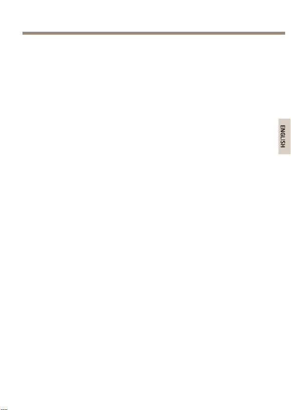
HardwareOverview
Illuminator
1
Photocell
2
Cable
3
Breathergland
8
Page 9

1
2
3
4
5
6
ENGLISH
AXIST90BSeries
1
2
3
4
5
6
Powercable(red)
Powercable(black)
Photocellcable(white)
Photocellcable(yellow)
Telemetrycable(purple)
Telemetrycable(orange)
9
Page 10
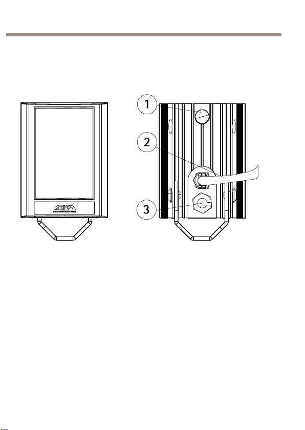
AXIST90BSeries
1
2
3
4
5
1
RedLEDindicator
2
AmberLEDindicator
3
GreenLEDindicator
4
Remotecontrolreceiver
5
Mountingbracket(pre-mounted)
10
Page 11
AXIST90BSeries
1
2
3
ENGLISH
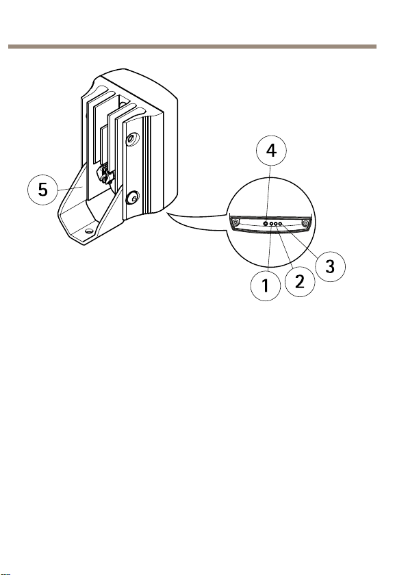
AXIST90B40IR-LED
1
Cables
2
Mountingbracket(pre-mounted)
3
Bolt
OptionalAccessories
RemoteControl
Forinformationhowtousetheremotecontrol,seeAccesstheProduct.
11
Page 12

AXIST90BSeries
1
2
3
4
5
6
7
8
9
1
POWERADJUSTbuttons
2
MountingBrackets
ToinstalltheproductusingacompatiblebracketfromAXIST90B
MountingAccessories,seetheInstallationGuidedeliveredseparatelywith
themountingbracket.
PHOTOCELLADJUSTbuttons
3
TIMERbuttons
4
Photocelldisablebutton
5
DIMbutton
6
RESETbutton
7
STATUSbutton
8
Disableremotecontrolsetupbutton
9
TELEMETRYbutton
12
Page 13

AXIST90BSeries
ENGLISH
LEDIndicators
TherearethreecoloredLEDindicatorsonthebaseoftheilluminatorwhich
provideoperatingandstatusinformation.Thecolorstatusdependson
thecurrentoperatingmode:
•ProgrammingMode
•NormalOperatingMode
ProgrammingMode
LEDIndicatorIndicatedBehavior
SolidGreen
FlashingGreen
SolidAmber
FlashingAmberIlluminatorinProgrammingMode
SolidRed
FlashingRed
NormalOperatingMode
Poweron
RemotecontrolIRreceivererror
Illuminatorreceivingvalid
commandfromremotecontrol
InternalLEDerror
Inputvoltagesupplyerror*
LEDIndicatorIndicatedBehavior
SolidGreen
FlashingGreen
Poweron
RemotecontrolIRreceivererror
13
Page 14

AXIST90BSeries
NormalOperatingMode(Continued)
SolidAmberInputvoltagelevelerror*
SolidRed
*Oncethevoltageerrorhasbeencorrected,disabletheremotecontrol
setuporrestarttheilluminatortoturnthestatusLEDoff.
InternalLEDerror
ConnectorsandButtons
Forspecicationsandoperatingconditions,seepage14.
PowerConnector
•AC/DCpowerconnector
Specications
OperatingConditions
ProductTemperatureHumidity
AXIST90BSeries-50°Cto50°C
PowerConsumption
ProductValue
AXIST90B15W-LED
AXIST90B20IR-LED
(-58°Fto122°F)
12–24VAC/DC,max12W
12–24VAC/DC,max24W
10–100%RH(condensing)
14
Page 15

AXIST90BSeries
1.5 m
ENGLISH
AXIST90B25W-LED
AXIST90B30IR-LED
AXIST90B35W-LED
AXIST90B40IR-LED
Formoreinformationaboutpowerconsumption,seeTechnical
Specicationsonpage29
12–24VAC/DC,max24W
12–24VAC/DC,max48W
12–24VAC/DC,max48W
12–24VAC/DC,max96W
InstalltheHardware
ToinstalltheproductusingacompatiblebracketfromAXIST90B MountingAccessories,seetheInstallationGuidedeliveredseparatelywith themountingbracket.
15
Page 16

AXIST90BSeries
CAUTION
Followtheseinstallationprocedures:
IRemittedfromthisproduct.Avoidprolongedeyeexposureor
useappropriateshieldingoreyeprotectionatdistancesofless
than1.5m.
1.Ifrequired,removethescrewsandmovethestandardbracket
tothetopoftheilluminator.
2.Ifrequired,loosenthescrewsandturnthebracket90°.
16
Page 17

AXIST90BSeries
ENGLISH
3.Ifrequired,loosenthescrewsandchangetoadiverging
lenswiththedesiredangleofillumination.Theangleof
illuminationshouldbeadjustedaccordingtothecameraeld
ofviewtolightthewholesceneadequately.SeeTechnical
Specications.
17
Page 18

AXIST90BSeries
2
1
1
Screws
2
Diverginglens
Note
Adjusttheverticalpositionoftheilluminatortoensurethatthe
eldofviewofthecameraisilluminated.
18
Page 19

AXIST90BSeries
ENGLISH
4.Positiontheilluminatoradjacenttothecameraandpointthe
illuminatortowardsthescene.
CAUTION
Redcable=+ve,Blackcable=-ve(polaritysensitive)
5.Mountthepowersupply.
6.Connecttheilluminatortothepowersupply .
19
Page 20

AXIST90BSeries
2
3
1
1
2
3
7.Setphotocellfollowingoutput(White&Yellow)Voltfree
output—normallyopen(day)tonormallyclosed(night).
Connectdirecttocameraifrequiredtocontrolswitchover
ofday/nightcameras.
AccesstheProduct
ProgrammingMode
Theilluminatorhasthefollowingdefaultsettings:
•Powersettomaximum100%
•Photocellsettomediumsensitivitylevel:10luxOn,30luxOff.
•Timerdisabled
Illuminator
Powercable
Powersupply
20
Page 21

•TelemetryTELenabled
ENGLISH
•Telemetryinputwiressolderedtogetherforautomatic
photocelloperation
•TelemetryDIMdisabled
•LEDstatusindicatorsenabled
•ProgrammingMode
Note
Changingthesettingsrequiresaremotecontrol(optional
accessory).TheilluminatormustbeinProgrammingMode.
TheilluminatorautomaticallyswitchesfromProgramming
ModetoNormalOperatingModeafter4weeks.Toswitchto
ProgrammingMode,restarttheilluminator.
1.Adjustthepower,seePowerAdjustonpage22.
2.Adjustthephotocellsensitivity,seePhotocellSensitivityon
page22.
3.Setthetelemetryinput:
-TEL,seepage24
-DIM,seepage25
-Timer,seepage25
4.DisabletheLEDstatusindicators,seeLEDStatusIndicators
onpage26.
5.Disableremotecontrolsetup,seeDisableRemoteControl
Setuponpage27.
6.Restorethefactorydefaultsettings,seeFactoryDefaulton
page27.
AXIST90BSeries
NormalOperatingMode
TheonlyfunctionoftheRemoteControlavailableduringNormalOperating
ModeisLEDStatusIndicators,seeLEDStatusIndicatorsonpage26.
21
Page 22

AXIST90BSeries
1
2
3
4
5
PowerAdjust
Thepoweroutputoftheilluminatorcanbeadjustedbetweenvepre-set
levels.Selecttherequiredlightintensitybyusingthebuttonsbelow.
1
20%ofmaximum
2
40%ofmaximum
3
PhotocellSensitivity
Note
Whenthephotocellisdisabledtheilluminatorwillturnonandoff
fromatelemetryinput,regardlessofambientlightingconditions.
60%ofmaximum
4
80%ofmaximum
5
100%ofmaximum
22
Page 23

AXIST90BSeries
1
2
3
4
ENGLISH
Therearethreepre-denedlevelstosettheluxlevelthresholdatwhich
thephotocellturnstheilluminatoronoroff.Selecttherequiredsensitivity
levelbyusingthebuttonsbelow.
1
Photocelldisabled
2
5LuxOn,15LuxOff
3
10LuxOn,30LuxOff
4
25LuxOn,50LuxOff
TelemetryInput
Thetelemetryinputwires(orangeandpurple)aredesignedtobeused
witharemoteswitchorinputfromanalarmsystem,PIRdetector,control
room,videomanagementsystemorcameraoutput.Theinputsignalcan
bevolt-freeorTTL.
23
Page 24

AXIST90BSeries
Volt-freeinput:
TTLinput:
Thetelemetryinputwires(orangeandpurple)aresolderedtogether
whenshippedfromthefactorytosimulateavolt-freeinputsothatthe
illuminatorautomaticallyturnsonandoffviathephotocell.Anyremote
inputorswitchshouldbeconnectedtothesewires.Sniptheendofthe
cableandseparatethecablestousewithremoteswitchorinput.
Undernormaloperatingconditions,atelemetryinputwillactivatetheunit
onlyatnightprovidedthatthephotocelldetectslowlightconditions.
However,ifthephotocellisdisabled,atelemetryinputwillactivatethe
unitregardlessofambientlightconditions.
Themodeofoperationisselectedbyusingtheremotecontrol.
Theremoteinputcanbeusedinconjunctionwiththeilluminatorinthe
followingways:
1.TEL—seepage24
2.DIM—seepage25
3.TEL+TIMER—seepage25
Telemetry-TEL
PresstheTELbuttoniftheilluminatoristobeturnedonandoffusing
aremoteswitchorinput.
TheTELinputcanbeusedinvariousways:
Nonpolaritysensitive
Shortcircuit=Lighton
Orange=TTL+ve
Purple=TTL-ve(GND)
0V=Lighton
3V=Lightoff
24
Page 25

AXIST90BSeries
ENGLISH
1.Turnthelighton(night)andoff(day)automaticallyviathe
photocell.Thisisthestandardfactorysetting,nofurther
actionisrequired.
2.Turnthelightonandofffromaremoteswitchorinput.
3.UsedinconjunctionwiththeTimerFunctiontoturnthelight
onforapre-denedperiodoftime.
Telemetry-DIM
Theremotedimmingfeatureallowsthebrightnessoftheilluminatortobe
controlledremotelyusingthetelemetryinputwires.UsetheDIMbutton
toselectthisfunction.
WhentheDIMfunctionisselected,atelemetryinputintotheilluminator
willvarythebrightnessupanddown.Whenthetelemetryinputisrst
applied,itwillstarttodimthelightandwillcontinuetodosowhilethe
telemetryinputisactive.Whentelemetryinputstops,thelightlevelwill
staywhereitwasset.Whenthetelemetryinputisactivatedforasecond
time,thelightwillstarttobrighten.Thiswillcontinuewhilethetelemetry
inputisactive.Thisactivationandde-activationofthetelemetryinput
willreversethewaythelightisdimmed(dimdownanddimup),toallow
theusertosetexactlythelevelrequired.DisabletheDIMfunctionby
pressingtheTELbutton.
AftersettingaspeciclightlevelusingtheDIMfunction,ifDIMisdisabled
andTELenabled,thelastpowerlevelsetwhenusingtheDIMfunction
willberememberedandusedbythesystemunlessanewpoweradjust
buttonisselected.
Timer
Thetimerfunctionallowstheilluminatortobetriggeredviaatelemetry
inputandremainonforapre-denedperiodoftime.Therearefour
pre-denedtimesandatimerdisablefunction.Toselecttimerfunction,
rstpressandreleasetheTELbutton,thenselectthedurationofthetimer
asshownbelow.
25
Page 26

AXIST90BSeries
1
2
3
4
5
6
Ifyouwishtocancelthetimerperiodandhavetheilluminatoroperate
understandardtelemetryconditions,pressTimerDisabled.
1
Timerdisabled
2
1minute
3
3minutes
4
10minutes
5
30minutes
6
TELbutton
LEDStatusIndicators
Thisstatusindicatorfunctioncanbeswitchedonandoffbypressingthe
STATUSbutton.Thisistheonlybuttonthathastwostates.Itispossible
forthisfunctiontobeenabledevenifProgrammingModehasbeen
disabledsothestatusoftheilluminatorcanbecheckedatanytime.
26
Page 27

AXIST90BSeries
ENGLISH
FactoryDefault
Note
Toactivatethisfeaturethebuttonmustbepressedcontinuously
for4seconds.Thisistoavoidthepossibilityofactivatingthis
featureaccidentally.
Oncetheilluminatorhasbeenprogrammed,thesettingswillbestoredina
non-volatile(stored)memory.Thesesettingsaresavedandreloadedifthe
illuminatorexperienceslossofpower.PresstheRESETbuttontorestore
theilluminatorbacktothefactorydefaultsettings.
DisableRemoteControlSetup
Note
ToenableProgrammingModeafterremotesetuphasbeen
disabled,theilluminatormustbepoweredoffforatleast
10seconds.Whenturnedon,theilluminatorautomatically
re-entersProgrammingMode.
Disableremotesetuponceanindividualilluminatorhasbeenprogrammed
andisdeliveringtherequiredoperatingperformance.Thiswillhelp
toavoidtamperingandthepossibilityofreceivingcommandswhen
programmingotherilluminatorsincloseproximity.
LocktheilluminatorsettingsbypressingtheDisableRemoteSetupbutton
continuouslyforatleast4seconds.
Ifremotecontrolsetupisnotdisabled,theilluminatorwillremainin
ProgrammingModeforapre-determinedtimeof4weeks.After4weeks,
remotecontrolsetupwillbeautomaticallydisabled.
Troubleshooting
Ensurealltestsareundertakenbyaqualied,trainedengineer.
Ensuresafeworkingpracticesarefollowedatalltimes.
27
Page 28

AXIST90BSeries
•Basics
-ChecktheLEDstatusindicator.SeeLEDIndicators.
-Checkpolarityoflampconnection:red=+ve,
-Ensurepoweris12-24VACorDC
-Ensuretelemetrywiresareshortedoutorclosed
-Checkphotocellisworking.Coverphotocellfully,
-Makesurethatthepowercableiswithinthe
•LampTest
Note
Usetheappropriatemultimeterdependingonhow
theilluminatorisbeingpowered(ACorDC).Cover
thephotocellfully(ordisablethephotocellusingthe
optionalremotecontrol)andmakesurethetelemetry
wiresareshortedoutorclosedcontactinput(zero
volt)isapplied.
-Checkthatthecurrentisbeingdrawn.Theamount
•SetupCamera,LensandIllumination
-Makesurethepowerissettomaximum.
-Checktheorientationofilluminatorandmakesure
-Checkangleofthediverginglens.Atoonarrow
black=-ve
contactinput(zerovolt)isapplied
lightshouldturnon.Itissometimesdifcultto
seeInfra-Redlampsworkinginhighbrightness
conditions.
specieddistance.
ofcurrentwilldependonthepowersettingofthe
illuminator.
itispointinginthecorrectdirection
anglemaycausehotspotsandtheapertureofthe
cameralenstoclosedown.Atoowideanglemay
causeinsufcientlightonthescene.
28
Page 29

•RemoteControl(optionalaccessory)
ENGLISH
TechnicalSpecications
Models
Supportedcameras
AXIST90BSeries
-PresstheSTATUSbuttontocheckthestatusofthe
remotecontrol,seeLEDStatusIndicators.
-Programmingmaybedisabled.Turntheilluminator
poweroffforatleast10secondsandthenturnthe
powerontoenterProgrammingMode.
-Inbrightsunlightconditions,thedistancebetween
theremotecontrolandtheilluminatormayneed
tobereduced.
-Checkthebatteryontheremotecontrol(CR2025),
replaceifnecessary.
-MakesurenootherstrongInfra-Redsourceis
pointingattheremotereceiver.
-Makesurethereisaclearlineofsitebetweenthe
illuminatorandtheremotecontrol.
-Checktheremotecontrolbattery.
AXIST90B15W-LED
AXIST90B25W-LED
AXIST90B35W-LED
AXIST90B20IR-LED
AXIST90B30IR-LED
AXIST90B40IR-LED
IR-LED:AllAxiscameraswithIRcutlter
W-LED:AllAxisnetworkcameras
29
Page 30

AXIST90BSeries
Power
Controltechnology
TypeIR-LED:850nmsemi-covert
Colortemperature
Angle10°withoutdiverginglens
InputVoltage:12-24VAC/DC
ACFrequenzy:50-60Hz
Cablelength2.5m(8ft)
PowerConsumptionmaximumlight/20%of
maximumlight/Standbymode:
AXIST90B15W-LED:12W/3W/0.15W
AXIST90B25W-LED:24W/6W/0.15W
AXIST90B35W-LED:48W/12W/0.15W
AXIST90B20IR-LED:24W/6W/0.15W
AXIST90B30IR-LED:48W/12W/0.15W
AXIST90B40IR-LED:96W/24W/0.15W
Powerlevel,Photocellsensitivity,Telemetrylink
forremoteactivation(ifrequired),Timer
W-LEDluminouspower:
AXIST90B15W-LED:733lm
AXIST90B25W-LED:1452lm
AXIST90B35W-LED:2840lm
5700K(validforW-LEDversionsonly)
Withdiverginglenses:
35°
60°
80°
120°*
*Optionalaccessory
30
Page 31

AXIST90BSeries
ENGLISH
Distance
AXIST90B20IR-LED
10°x10°-120m(394ft)*
35°x10°-65m(213ft)
60°x25°-45m(148ft)
80°x30°-30m(98ft)
120°x50°-20m(66ft)**
AXIST90B30IR-LED
10°x10°-220m(722ft)*
35°x10°-120m(394ft)
60°x25°-65m(213ft)
80°x30°-45m(148ft)
120°x50°-30m(98ft)**
AXIST90B40IR-LED
10°x10°-310m(1010ft)*
35°x10°-170m(551ft)
60°x25°-112m(367ft)
80°x30°-70m(230ft)
120°x50°-65m(213ft)**
AXIST90B15W-LED
10°x10°-50m(164ft)*
35°x10°-35m(1 15ft)
60°x25°-20m(66ft)
80°x30°-15m(49ft)
120°x50°-10m(33ft)**
AXIST90B25W-LED
10°x10°-90m(295ft)*
35°x10°-55m(180ft)
60°x25°-30m(98ft)
80°x30°-20m(66ft)
120°x50°-15m(49ft)**
AXIST90B35W-LED
10°x10°-150m(492ft)*
35°x10°-80m(262ft)
60°x25°-45m(148ft)
31
Page 32

AXIST90BSeries
Casing
DisplayandindicatorsLEDindicators
Environment
MountingWall
Approvals
Operatingconditions
80°x30°-30m(98ft)
120°x50°-20m(66ft)**
*Nodiverginglens
**Optionalaccessory
Material:Polycarbonate
IR-LED:Black
W-LED:Whiteandsilver
Outdoor
Ceiling
Column
Camerahousing
EN55022ClassB,EN55024
EN61547,EN55015,EN50130–4
C-tickAS/NZSCISPR22ClassB
FCCPart15SubpartBClassB
ICES–003ClassB
KCCKN22ClassB,KN24
IEC/EN60598–1
IEC/EN62471Riskgroup2*
IEC/EN60529IP66
REACH,WEEE,CE
*ValidonlyforIR-LEDproducts
-50°Cto50°C(-58°Fto122°F)
10–100%RH(condensing)
32
Page 33

AXIST90BSeries
ENGLISH
Dimensions(HxWxL)
Weight
Includedaccessories3diverginglenses:
Optionalaccessories
Thesizeoftheproductshallbemaximum
(WxHxL):
AXIST90B15W-LED:75x100x64mm(3x
4x2.5in)
AXIST90B25W-LED:100x135x66mm(4x
5x2.5in)
AXIST90B35W-LED:135x180x68,2mm(5x
7x3.2in)
AXIST90B20IR-LED:100x135x66mm(4x
5x2.5in)
AXIST90B30IR-LED:135x180x68,2mm(5x
7x3.2in)
AXIST90B40IR-LED:279x223x68mm(1 1
x9x3in)
AXIST90B15W-LED:600g(1.3lbs)
AXIST90B25W-LED:950g(2.1lbs)
AXIST90B35W-LED:1650g(3.6lbs)
AXIST90B20IR-LED:950g(2.1lbs)
AXIST90B30IR-LED:1650g(3.6lbs)
AXIST90B40IR-LED:4500g(9.9lbs)
35°(pre-mounted)
60°
80°
Powersupply
Mountingbrackets
AXIST90BRemoteControl
Diverginglens(120°angle)
FurtherInformation
VisitAxislearningcenterwww.axis.com/academyforusefultrainings,
webinars,tutorialsandguides.
33
Page 34

AXIST90BSeries
WarrantyInformation
ForinformationaboutAxis’productwarrantyandtheretorelated
information,seewww.axis.com/warranty/
34
Page 35

35
Page 36

InstallationGuide
AXIST90BSeries
©AxisCommunicationsAB,2014
Ver.M3.2
Date:August2014
PartNo.59159
 Loading...