

Page 1

INSTALLATION GUIDE
ENGLISH FRANÇAIS DEUTSCH ITALIANO ESPAÑOL
日本語
AXIS T8120 Midspan 15 W 1-port
Page 2
Legal Considerations
Video and audio surveillance can be prohibited
by laws that vary from country to country. Check
the laws in your local region before using this
product for surveillance purposes.
Electromagnetic Compatibility (EMC)
USA -
Using an unshielded network cable
(UTP): This equipment has been tested using an
unshielded network cable (UTP) and found to
comply with the limits for a Class A digital
device, pursuant to part 15 of the FCC Rules.
These limits are designed to provide reasonable
protection against harmful interference when
the equipment is operated in a commercial
environment. This equipment generates, uses,
and can radiate radio frequency energy and, if
not installed and used in accordance with the
instruction manual, may cause harmful
interference to radio communications. Operation
of this equipment in a residential area is likely to
cause harmful interference in which case the
user will be required to correct the interference
at his own expense. Using a shielded network
cable (STP): This equipment has also been tested
using a shielded network cable (STP) and found
to comply with the limits for a Class B digital
device, pursuant to part 15 of the FCC Rules.
These limits are designed to provide reasonable
protection against harmful interference in a
residential installation. This equipment
generates, uses and can radiate radio frequency
energy and, if not installed and used in
accordance with the instructions, may cause
harmful interference to radio communications.
However, there is no guarantee that interference
will not occur in a particular installation. If this
equipment does cause harmful interference to
radio or television reception, which can be
determined by turning the equipment off and
on, the user is encouraged to try to correct the
interference by one or more of the following
measures:
• Reorient or relocate the receiving antenna.
• Increase the separation between the
equipment and receiver.
• Connect the equipment into an outlet on a
circuit
• Consult the dealer or an experienced radio/TV
technician for help.
Europe - This digital equipment fulfills
the requirements for RF emission according to
the Class B limit of EN 55022.
The product shall be connected using a shielded
network cable (STP) that is properly grounded.
This product fulfills the requirements for
immunity according to EN 55024 office and
commercial environments.
Japan -
この装置は、クラスB 情報技術装置です。この
装置は、家庭環境で使用することを目 的としていますが
、この装置がラジオやテレビジョン受信機に近接して使
用されると、 受信障害を引き起こすことがあります。
取扱説明書に従って正しい取り扱いをして下さい。
Canada - This digital apparatus complies with
CAN ICES-3 (Class B). The product shall be
connected using a shielded network
cable (STP) that is properly grounded.
Cet appareil numérique est conforme à la norme
CAN NMB-3 (classe B). Le produit doit être
connecté à l'aide d'un câble réseau blindé (STP)
qui est correctement mis à la terre.
Australia - This digital equipment fulfills the
requirements for RF emission according to the
Class B limit of AS/NZS CISPR 22. The product
shall be connected using a shielded network
cable (STP) that is properly grounded.
Safety
This product complies with IEC/EN/UL 60950-1,
Safety of Information Technology Equipment.
Disposal and Recycling
When this product has reached the end of its
useful life, dispose of it according to local raws
and regulations. For information about your
nearest designated collection point, contact
your local authority responsible for waste
disposal. In accordance with local legislation,
penalties may be applicable for incorrect
disposal of this waste.
RoHS
This product complies with both the
European RoHS directive, 2002/95/EC,
and the Chinese RoHS regulations,
ACPEIP.
WEEE Directive
The European Union has enacted a
Directive 2002/96/EC on Waste
Electrical and Electronic Equipment
(WEEE Directive). This directive is
applicable in the European Union
member states.
The WEEE marking on this product (see right) or
its documentation indicates that the product
must not be disposed of together with
household waste. To prevent possible harm to
human health and/or the environment, the
product must be disposed of in an approved and
environmentally safe recycling process. For
further information on how to dispose of this
product correctly, contact the product supplier,
or the local authority responsible for waste
disposal in your area.
Business users should contact the product
supplier for information on how to dispose of
this product correctly. This product should not
be mixed with other commercial waste. For more
information, visit www.axis.com/techsup/.
Korea -
ࢇЕɼࢽࡈ%ࢷળࢶଢԻ۰
࣯Իɼࢽ߾۰یࡈଜЕʨࡶּࢶࡳԻଜֲֻҘ
ࠇ߾۰یࡈଟܹݡТЬ
Page 3

Intellectual Property Rights
Axis AB has intellectual property rights relating
to technology embodied in the product
described in this document. In particular, and
without limitation, these intellectual property
rights may include one or more of the patents
listed at http://www.axis.com/patent.htm and
one or more additional patents or pending
patent applications in the US and other
countries.
Support
Should you require any technical assistance,
please contact your Axis reseller. If your
questions cannot be answered immediately, your
reseller will forward your queries through the
appropriate channels to ensure a rapid response.
If you are connected to the Internet, you can:
• download user documentation and firmware
updates
• find answers to problems in the FAQ database.
Search by product, category, phrases.
• report problems to Axis support by logging in
to your private support area.
• chat with Axis support staff (selected
countries only)
• visit Axis Support at www.axis.com/techsup/
Liability
Every care has been taken in the preparation of
this document. Please inform your local Axis
office of any inaccuracies or omissions. Axis
Communications AB cannot be held responsible
for any technical or typographical errors and
reserves the right to make changes to the
product and documentation without prior
notice. Axis Communications AB makes no
warranty of any kind with regard to the material
contained within this document, including, but
not limited to, the implied warranties of
merchantability and fitness for a particular
purpose. Axis Communications AB shall not be
liable nor responsible for incidental Support or
consequential damages in connection with the
furnishing, performance or use of this material.
This product is only to be used for its intended
purpose.
Equipment Modifications
This equipment must be installed and used in
strict accordance with the instructions given in
the user documentation. This equipment
contains no user-serviceable components.
Unauthorized equipment changes or
modifications will invalidate all applicable
regulatory certifications and approvals.
Notice
Axis’ policy is to improve its products as new
technology, components, software, and firmware
become available. Axis, therefore, reserves the
right to change specifications without prior
notice.
Trademarks
The product described in this guide is a licensed
product of PowerDsine.
Contact Information
Axis Communications AB
Emdalavägen 14
223 69 Lund, Sweden
Tel: +46 46 272 18 00
Fax: +46 46 13 61 30
www.axis.com
Page 4

Page 5

AXIS T8120 Installation Guide Page 5
ENGLISH
AXIS T8120 Installation Guide
Safety Information
• When transporting the Axis product, use the original packaging or
equivalent to prevent damage to the product.
• Store the Axis product in a dry and ventilated environment.
• Avoid exposing the Axis product to vibration, shocks or heavy pressure and do not install the product on unstable brackets, since this
could cause damage to the product.
• Do not attempt to repair the product by yourself, contact Axis or
your Axis reseller for service matters.
• The product should connected to PoE networks only, without
routing to the outside plant.
• Only qualified personnel can install or remove the product.
• The power cord must have regulatory agency approval for the
specific country in which is used, (for example UL, CSA, VDE on).
• The power cord must be a three-conductor type (two current carrying conductors, one ground conductor) terminated on one end by
an IEC 60320 appliance coupler (for connecting to the product) and
on the other end by a plug containing a ground (earthing) contact.
The power cord must be rated for a minimum of 250 V AC RMS
operation, with a minimum rated current
capacity of 5 amps (or a minimum wire gauge of 18 AWG (0.75
mm2).
• A product installed in Australia requires power cords with a
minimum wire gauge of 16 AWG (1.0 mm2).
• The products “DATA IN” and “DATA & POWER OUT” ports are
shielded RJ45 data sockets. They cannot be used as Plain Old Telephone Service (POTS) telephone sockets. Only RJ45 data connectors
can be connected to these sockets.
Page 6

Page 6 AXIS T8120 Installation Guide
• The AC wall socket outlet must be near the product and easily
accessed. AC power can be removed from the product by
disconnecting the AC power cord from either the wall socket-outlet or from the products appliance coupler.
• The products “DATA IN” and “DATA & POWER OUT” interfaces are
qualified as Safety Extra-low Voltage (SELV) circuits according to
IEC 60950-1. These interfaces can only be connected to SELV
interfaces on other equipment.
• The product should only be connected to the IP device with which
it was bought. Using the product with other IP devices can cause
damage to the IP device.
• Follow basic electricity safety measures whenever connecting the
device to its power source.
• Read the installation instructions before connecting the product to
its power source.
• A voltage mismatch can cause equipment damage and may pose a
fire hazard. If the voltage indicated on the label is different from
the power outlet voltage, do not connect the product to this power
outlet.
• The product can be used only in Restricted Access Locations.
Page 7

AXIS T8120 Installation Guide Page 7
ENGLISH
Functions and Features
The Power over Ethernet (PoE) Midspan adds 48V DC to unused (nondata) wires (Mode B) in a standard Category 5 Ethernet cable. As a
result, the PoE Midspan delivers both data and power to the terminal.
The device is designed to meet the IEEE802.3af standard.
Preliminary steps
• Ensure AC power is applied to the PoE Midspan using an
operational AC cable with an appropriate ground connection.
• Ensure that output Ethernet cable is connected to the
Data & Power Out port.
• Verify that a power ready Ethernet compatible device is connected.
Note: Do not use a cross over cable between the PoE Midspan
output port and the load device.
Mounting
Note the following before mounting the PoE Midspan to a fixed location:
• The PoE Midspan may be wall or bench mounted using the rear
side holes.
• Do not cover the PoE Midspan or block the airflow to the PoE with
any foreign objects. Keep the PoE Midspan away from
excessive heat and humidity, and keep it free from vibration
and dust.
• Ensure that the cable length from the Ethernet network source to
the terminal does not exceed 100 meters (333 ft). The PoE is not a
repeater and does not amplify the Ethernet data signal.
• Use a splitter if desired, ensure that the splitter is connected close
to the terminal and not on the Midspan.
• There is no "on-off" switch, simply plug the PoE Midspan to an
AC power source.
Page 8
Page 8 AXIS T8120 Installation Guide
Installing the Unit
1. Connect the PoE Midspan to an AC outlet (100-240 V AC), using a
standard power cable.
2. Connect the unit Data In jack (input) to the remote Ethernet
network switch Patch panel.
3. Connect the Data & Power Out jack (output) to the terminal.
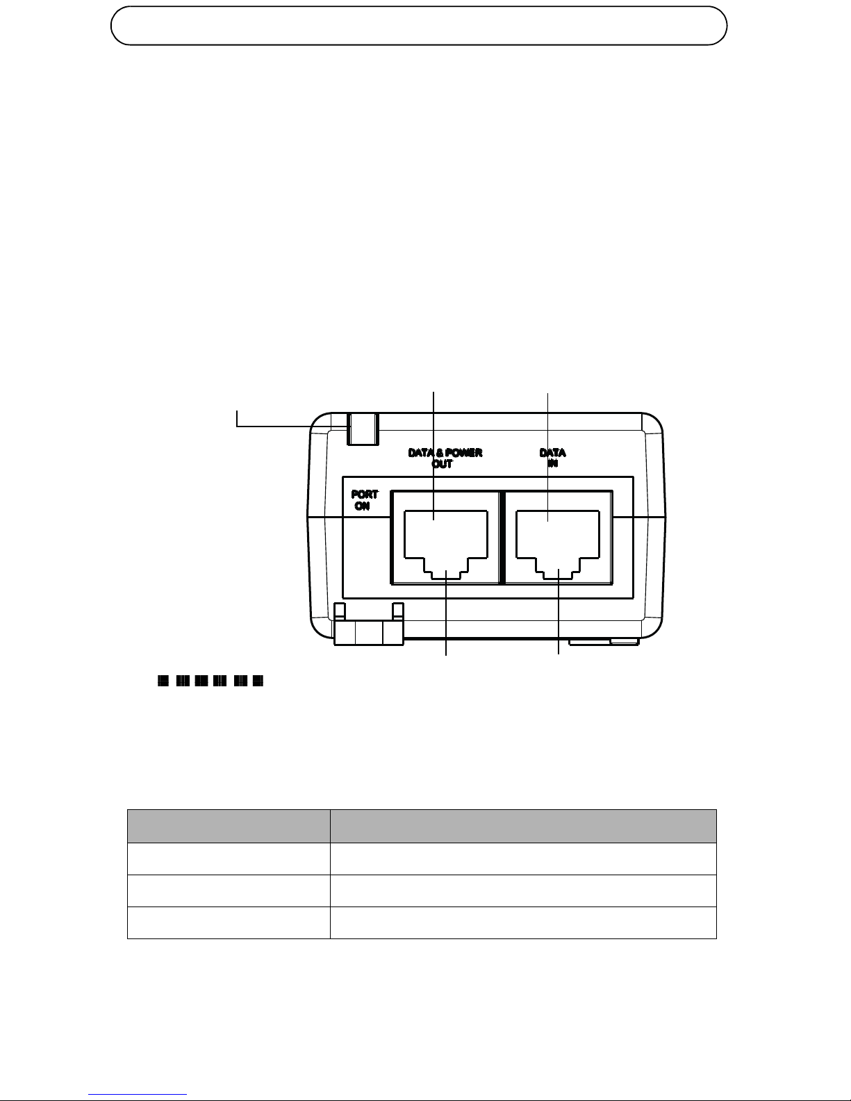
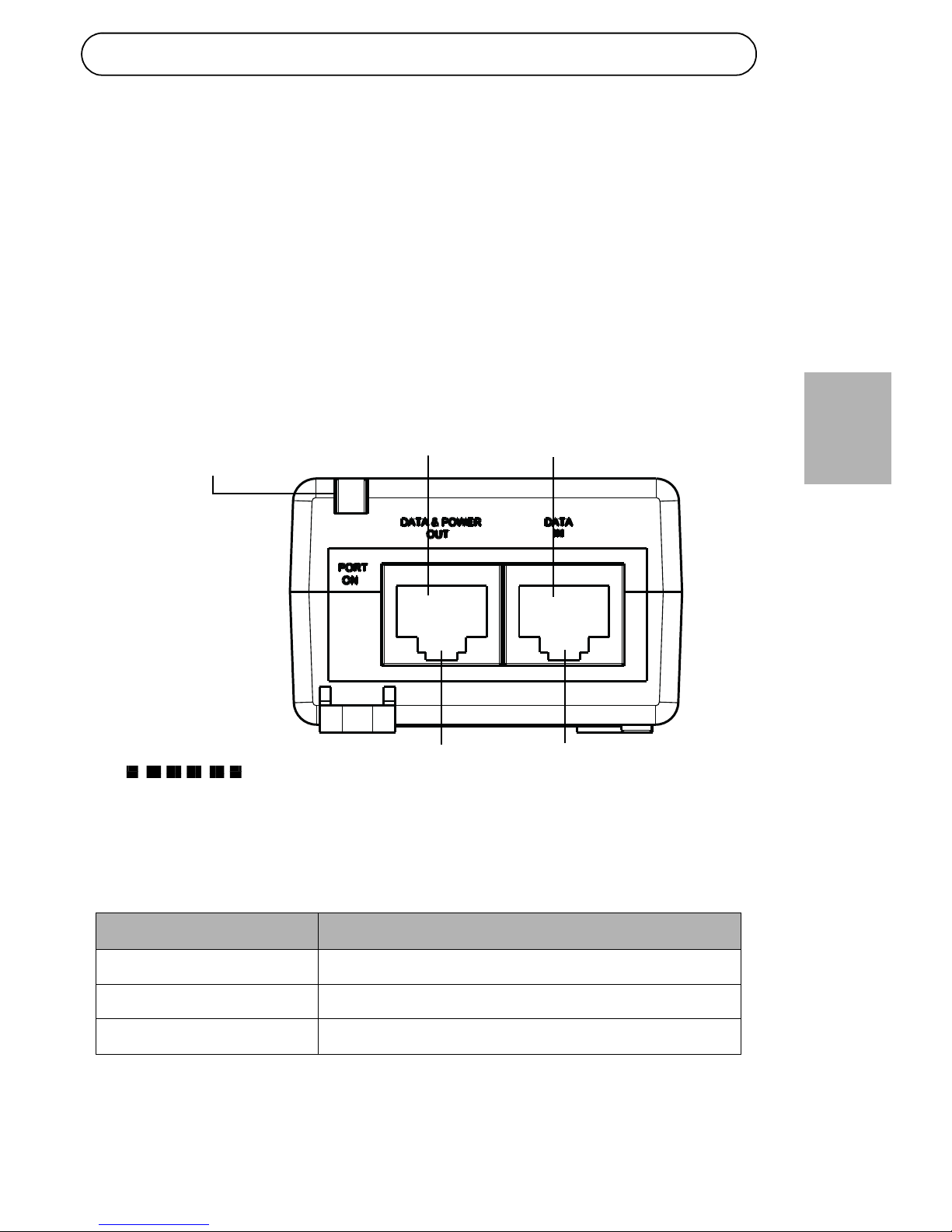
Hardware Overview
Indicators
LED Indicated Behavior
Yellow On
Power is on (power is active)
Green On
A remote terminal is connected
Green Blinking
Overload state or short-circuit
CAT 5 C ab le
Port connectivity Data and Power out Data in
indicator
Output port Input port
Terminal Ethernet
Page 9
AXIS T8120 Installation Guide Page 9
ENGLISH
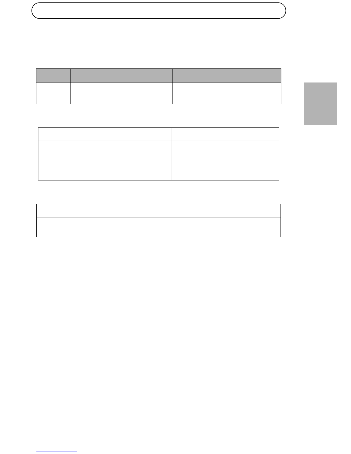
Specifications
Environmental Specifications
Electrical Specifications
Ethernet Interface
Mode Temperature Humidity
Operating
0 °C to 40 °C (32 °F to 104 °F)
10 to 90% RH (no condensation
allowed)
Storage
-20 °C to 70 °C (-4 °F to 158 °F)
Input voltage
100 to 240V AC (50/60 Hz)
Input current
0.5 A (maximal)
Available Output Power (Maximum) 16.8 W
Nominal Output Voltage 48V DC
Input (Data In): Ethernet 10/100Base-T RJ45 female socket
Output (Data & Power Out):
Ethernet 10/100Base-T, plus 48 VDC
RJ45 female socket, with DC
voltage on wire pairs 4-5 and 7-8.
Page 10
Page 10 AXIS T8120 Installation Guide
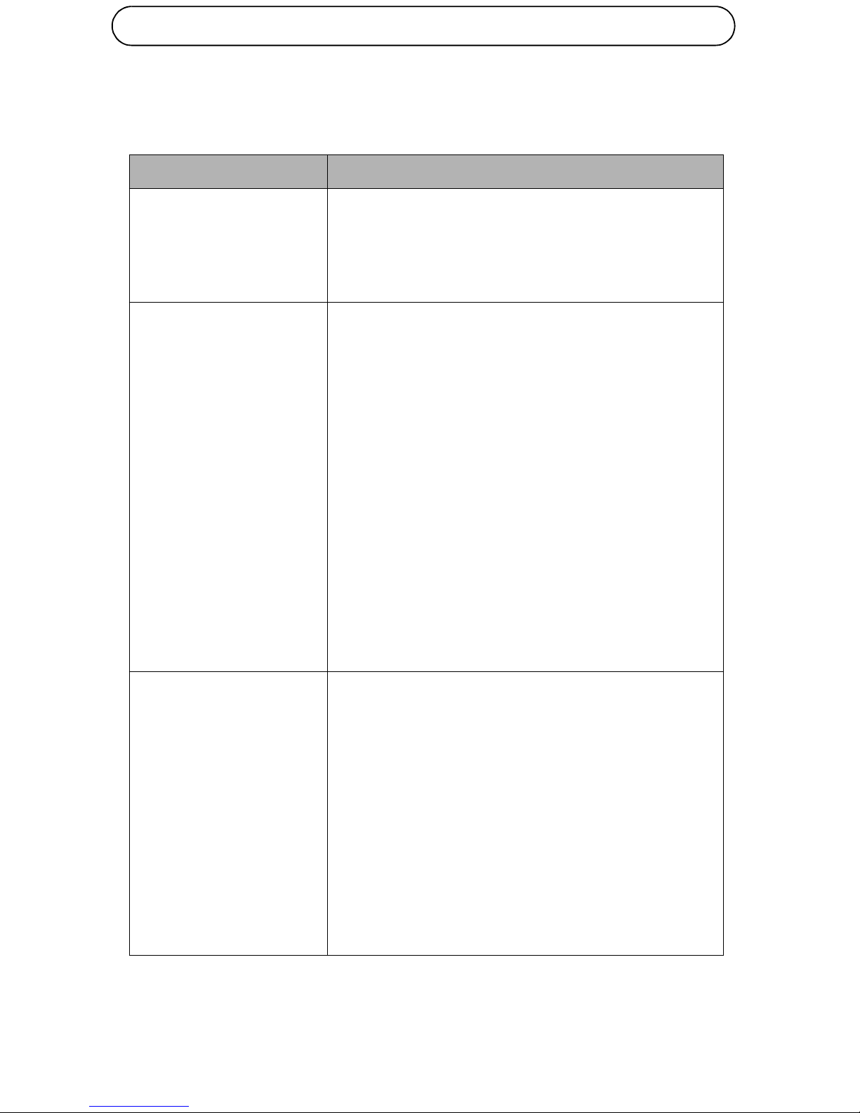
Troubleshooting
Symptom Corrective Steps
Midspan does not power up1. Verify that an approved power cord is used.
2. Verify that the voltage at the power inlet is
between 100 and 240V AC.
3. Remove and re-apply power to the device and
check the indicators during power up sequence.
A port indicator is not lit
and the Midspan does not
operate
1. The Midspan did not detect a device and
therefore the port is not enabled.
2. Verify that the device is designed for PoE
operation
3. Verify that you are using a standard Category 5/
5e/6, straight-wired cable, with four pairs
4. If there is a connected external power splitter,
replace it to verify that it is functioning properly
5. Ensure that the input Ethernet cable is connected
to the Data In port
6. Verify that the device is connected to the Data &
Power port.
7. Try to reconnect the same device into a different
Midspan. If it works, there is probably a faulty
port or RJ45 connection.
8. Verify that there is no short over any of the
twisted pair cables or over the RJ45 connectors.
The end device operates,
but there is no data link
1. Verify that the port indicator on the front panel is
continuously lit.
2. If an external power splitter is in use, replace it
with a known-good splitter.
3. Verify that for this link, you are using standard
UTP/FTP Category 5 straight (non-crossover)
cabling, with all four pairs.
4. Verify that the Ethernet cable length is less than
100 meters from the Ethernet source to the load/
remote terminal.
5. Try to reconnect the same device into a different
Midspan. If it works, there is probably a faulty
port or RJ45 connection.
Page 11

AXIS T8120 Installation Guide Page 11
ENGLISH
Warranty Information
For information about Axis’ product warranty and thereto related information, see
www.axis.com/warranty/
Page 12

Page 13

AXIS T8120 Guide d'installation Page 13
FRANÇAIS
AXIS T8120 Guide d’installation
Informations sur la sécurité
• Lors du transport du produit Axis, utiliser l'emballage d'origine ou
un équivalent pour éviter d'endommager le produit.
• Conserver ce produit Axis dans un environnement sec et ventilé.
• Éviter d'exposer le produit Axis à des vibrations, des chocs ou une
trop forte pression et ne pas l'installer sur des supports instables,
car cela risquerait de l'endommager.
• Ne pas tenter de réparer le produit vous-même, contacter Axis ou
votre revendeur Axis pour toute réparation.
• Ce produit doit être uniquement connecté à un réseau alimenté par
Ethernet (PoE), sans routage extérieur.
• Seul un personnel technique qualifié est autorisé à installer ou démonter ce produit.
• Le cordon d'alimentation doit être homologué par l'organisme de
réglementation habilité par le pays dans lequel il est utilisé (par
exemple UL, CSA, VDE).
• Le cordon d'alimentation doit être muni de trois conducteurs (deux
conducteurs d'électricité et un conducteur de terre) avec à l'une
extrémité une prise de courant femelle IEC 60320 (pour la
connexion au produit) et à l'autre extrémité une prise comportant
une connexion de terre (masse). Le cordon d'alimentation doit être
prévu pour une utilisation sur une tension minimale de 250 V CA
RMS, avec une capacité nominale d'au moins 5 ampères (ou un calibre minimal de 18 AWG (0,75 mm2).
• Tout produit installé en Australie doit être équipé d'un cordon d'alimentation d'un calibre minimal de 16 AWG (1,0 mm2).
• Les ports “DATA IN” et “DATA & POWER OUT” sont des prises de
données RJ45 protégées. Elles ne doivent pas être utilisée en tant
que prises de services téléphoniques traditionnels (POTS). Seuls les
connecteurs de données RJ45 peuvent être connectés à ces prises.
Page 14

Page 14 AXIS T8120 Guide d'installation
• La prise de courant murale doit se trouver à proximité de l'équipement et être facilement accessible. Il est possible de couper l'alimentation en débranchant le cordon d'alimentation de la prise
murale ou de la prise de l'appareil.
• Les interfaces “DATA IN” et “DATA & POWER OUT” de ce produit satisfont aux exigences de Très basse tension de sécurité (TBTS),
conformément à la norme IEC 60950-1. Ces interfaces peuvent
être uniquement connectées à des interfaces TBTS d'autres équipements.
• Ce produit doit être uniquement connecté à l'appareil IP avec lequel il a été acheté. L'utilisation de ce produit avec d'autres appareils IP pourrait les endommager.
• Suivre les mesures de sécurité électrique de base lors de chaque
raccordement de l'appareil à sa source d'alimentation.
• Avant le branchement du produit à sa source d'alimentation, lire
les instructions d'installation.
• Un défaut d'appariement de la tension peut endommager l'équipement et représenter un risque d'incendie. Si la tension indiquée sur
l'étiquette est différente de la tension de sortie, ne pas brancher ce
produit à la prise de courant.
• Ce produit doit être utilisé uniquement dans un lieu à accès restreint.
Page 15

AXIS T8120 Guide d'installation Page 15
FRANÇAIS
Fonctions et caractéristiques
L'injecteur d'alimentation par Ethernet (PoE) ajoute 48 V CC aux fils non
utilisés (ne servant pas à la transmission des données) (en Mode B) d'un
câble Ethernet standard de catégorie 5. L'injecteur PoE peut donc
alimenter le terminal aussi bien en données qu'en électricité. Il est
conforme à la norme IEEE802.3af.
Étapes préliminaires
• Vérifiez que l'injecteur PoE est raccordé à un câble CA en bon état
de fonctionnement et correctement mis à la terre.
• Vérifiez que le câble Ethernet de sortie est branché sur le port de
données et d'alimentation de sortie.
• Vérifiez qu'un appareil compatible Ethernet est connecté.
Remarque : N'utilisez pas de câble simulateur de modem entre le
port de sortie de l'injecteur PoE et le dispositif de chargement.
Montage
Veuillez prendre note de ce qui suit avant le montage de l'injecteur PoE :
• L'injecteur PoE peut être fixé au mur ou monté sur banc à l'aide des
trous situés au dos de l'appareil.
• Ne recouvrez pas l'injecteur POE et ne bloquez pas la circulation
d'air par des corps étrangers. Conservez l'injecteur PoE à l'abri de
toute chaleur ou humidité excessive, des vibrations et de la poussière.
• Veillez à ce que la longueur de câble entre la source du réseau
Ethernet et le terminal ne dépasse pas 100 mètres. Le PoE n'est pas
un répéteur et n'amplifie pas le signal des données Ethernet.
• Le cas échéant, utilisez un diviseur et assurez-vous qu'il est raccordé près du terminal et pas sur l'injecteur.
Page 16

Page 16 AXIS T8120 Guide d'installation
• Il n'y a pas d'interrupteur Marche/Arrêt. Il suffit donc de brancher
l'injecteur PoE sur une prise de courant CA pour le mettre en
marche.
Page 17
AXIS T8120 Guide d'installation Page 17
FRANÇAIS
Installation de l'appareil
1. Branchez l'injecteur PoE sur une prise de courant (100-240 V CA), à
l'aide d'un cordon d'alimentation ordinaire.
2. Branchez la prise DATA IN (données d'entrée) de l'appareil sur le
tableau de connexions du réseau Ethernet distant.
3. Branchez la prise DATA & POWER OUT (sortie) sur le terminal.
Vue d'ensemble du matériel
Voyants
Voyant DEL Comportement
Jaune continu
L'appareil est sous tension (alimenté en courant)
Vert continu
Un terminal distant est connecté
Vert clignotant
Surcharge ou court-circuit
CAT 5 C ab le
Voyant de connectivité Entrée des données
Port de sortie du terminal Port d'entrée Ethernet
Sortie des données
et d'alimentation
Page 18

Page 18 AXIS T8120 Guide d'installation
Caractéristiques
Spécifications environnementales
Caractéristiques électriques
Interface Ethernet
Mode Température Humidité
En
fonctionnement
De 0 °C à 40 °C
Humidité relative de 10 à 90 %
(sans condensation)
Stockage
-20 °C à 70 °C
Tension d'entrée
100 à 240 V CA (50/60 Hz)
Courant d'entrée
0,5 A (maximal)
Puissance de sortie disponible (maximum) 16,8 W
Tension de sortie nominale 48 V CC
Entrée (DATA IN) : Ethernet 10/100Base-T Prise femelle RJ45
Sortie (DATA & POWER OUT) :
Ethernet 10/100Base-T, plus 48 V CC
Prise femelle RJ45, avec tension
continue sur les paires de conducteur 4-5 et 7-8.
Page 19

AXIS T8120 Guide d'installation Page 19
FRANÇAIS
Dépannage
Symptôme Mesures à suivre
L'injecteur ne se met pas
sous tension.
1. Vérifiez que le cordon d'alimentation utilisé est
homologué.
2. Vérifiez que la tension en entrée se situe entre
100 et 240 V CA.
3. Mettez l'appareil hors tension et rallumez-le en
vérifiant les voyants pendant la mise sous
tension.
Un voyant de port est éteint
et l'injecteur ne fonctionne
pas.
1. L'injecteur n'a détecté aucun appareil. Le port est
donc désactivé.
2. Vérifiez que l'appareil peut fonctionner en mode
PoE.
3. Vérifiez que vous utilisez un câble à fils droits
ordinaire de catégorie 5/5e/6, à quatre paires.
4. Si un diviseur d'alimentation externe est utilisé,
remplacez-le pour vous assurer qu'il fonctionne
correctement.
5. Vérifiez que le câble Ethernet d'entrée est
branché sur le port Data In.
6. Vérifiez que l'appareil est bien raccordé au port
DATA & POWER OUT.
7. Essayez de rebrancher le même appareil sur un
injecteur différent. Si cela fonctionne, il est
probable que l'un des ports ou la connexion RJ45
soit défectueux.
8. Vérifiez qu'il n'y a pas de court-circuit sur les
câbles à paires torsadées ni sur les connecteurs
RJ45.
Page 20

Page 20 AXIS T8120 Guide d'installation
Informations sur la garantie
Pour obtenir de plus amples informations sur la garantie du produit AXIS et des
renseignements connexes, allez sur le site www.axis.com/warranty/
L'appareil fonctionne, mais
aucune liaison de données
n'est établie
1. Vérifiez que le voyant de port à l'avant de
l'appareil est allumé en continu.
2. Si un diviseur d'alimentation externe est utilisé,
remplacez-le par un diviseur que vous savez en
bon état de fonctionnement.
3. Vérifiez que, pour cette liaison, vous utilisez un
câble droit UTP/FTP ordinaire de catégorie 5 (et
non un câble simulateur de modem), avec les
quatre paires.
4. Vérifiez que le câble Ethernet, entre la source
Ethernet et le terminal distant/de charge, mesure
moins de 100 mètres.
5. Essayez de rebrancher le même appareil sur un
injecteur différent. Si cela fonctionne, il est
probable que l'un des ports ou la connexion RJ45
soit défectueux.
Page 21

AXIS T8120 Installationsanleitung Seite 21
DEUTSCH
AXIS T8120 Installationsanleitung
Sicherheitsinformation
• Transportieren Sie das Axis Produkt ggf. in der Originalverpackung
oder einer entsprechenden Verpackung, sodass Schäden vermieden
werden.
• Lagern Sie das Axis Produkt in einer trockenen und belüfteten Um-
gebung.
• Achten Sie darauf, dass das Axis Produkt keinen Erschütterungen,
Stößen bzw. keinem starken Druck ausgesetzt ist und montieren
Sie das Produkt nicht an instabilen Halterungen. Dies kann zu einer
Beschädigung des Produkts führen.
• Versuchen Sie nicht, das Produkt selbst zu reparieren. Wenden Sie
sich bezüglich Reparatur und Wartung an Axis oder an Ihren Axis
Händler.
• Das Produkt darf nur an PoE-Netzwerke ohne Außenanbindung angeschlossen werden.
• Das Produkt darf nur von qualifiziertem Personal installiert oder
entfernt werden.
• Das Netzkabel muss über die Zulassung für das jeweilige Land verfügen (z. B. UL, CSA, VDE usw.).
• Es muss sich um ein dreiadriges Netzkabel handeln (zwei für die
Stromversorgung und ein Erdungsleiter), das an einem Ende mit einem IEC 60320-Gerätestecker (zum Anschließen des Produkts) and
am anderen Ende mit einem Schuko-Stecker versehen ist. Das
Netzkabel muss mindestens für den Betrieb mit 250 V AC RMS mit
einer minimalen Nennstromstärke von 5 A zugelassen sein (bzw. einem Mindestquerschnitt von 18 AWG (0,75 mm2) aufweisen).
• Für in Australien installierte Produkte ist ein Netzkabel mit einem
Mindestquerschnitt von 16 AWG (1,0 mm2) erforderlich.
Page 22

Seite 22 AXIS T8120 Installationsanleitung
• Bei den Ports DATA IN und DATA & POWER OUT des Produkts handelt es sich um isolierte RJ-45-Datenbuchsen. Sie können nicht als
POTS-Telefonbuchsen verwendet werden. An diese Buchsen können ausschließlich RJ-45-Datenstecker angeschlossen werden.
• Die Steckdose muss sich leicht zugänglich in der Nähe des Produkts
befinden. Das Produkt kann vom Stromnetz getrennt werden, indem das Netzkabel entweder von der Steckdose oder der Buchse
des Produkts getrennt wird.
• Bei den Anschlüssen DATA IN und DATA & POWER OUT des Produkts handelt es sich um Schutzkleinspannungsstromkreise (SELV)
gemäß IEC 60950-1. Diese Schnittstellen können nur an SELVSchnittstellen anderer Geräte angeschlossen werden.
• Das Produkt darf nur an das IP-Gerät angeschlossen werden für das
es vorgesehen wurde. Die Verwendung des Produkts mit anderen
IP-Geräten kann das IP-Gerät beschädigen.
• Halten Sie sich an die grundlegenden Sicherheitsmaßnahmen für
elektrische Arbeiten, wann immer Sie das Gerät an die Steckdose
anschließen.
• Lesen Sie die Installationsanweisungen, bevor Sie das Produkt an
die Stromversorgung anschließen.
• Falsche Spannung kann das Produkt beschädigen und Brände verursachen. Wenn sich die auf dem Etikett angegebene Spannung
von der Spannung der Steckdose unterscheidet, schließen Sie das
Produkt nicht an diese Steckdose an.
• Das Produkt darf nur Orten mit Zugangsbeschränkung verwendet
werden.
Page 23

AXIS T8120 Installationsanleitung Seite 23
DEUTSCH
Funktionen und Merkmale
Der PoE-Midspan (Power over Ethernet) überträgt 48 V Gleichstrom über
ungenutzte (nicht Daten führende) Leiter (Modus B) eines StandardEthernet-Kabels der Kategorie 5. Damit überträgt der PoE-Midspan
sowohl Daten als auch Strom an das Endgerät. Das Gerät entspricht dem
Standard IEEE802.3af.
Vorbereitende Schritte
• Stellen Sie sicher, dass der PoE-Midspan über ein unbeschädigtes,
geerdetes Netzkabel mit Strom versorgt wird.
• Stellen Sie sicher, dass das ausgehende Ethernet-Kabel am Port
„Data & Power Out“ angeschlossen ist.
• Prüfen Sie, ob ein netzstromfähiges, Ethernet-kompatibles Gerät
angeschlossen ist.
Hinweis: Verwenden Sie kein Verbindungskabel zwischen dem
Ausgangs-Port am PoE-Midspan und dem Lastgerät.
Montage
Beachten Sie vor der ortsfesten Montage des PoE-Midspan Folgendes:
• Der PoE-Midspan kann mithilfe der Bohrungen an der Rückseite
entweder an der Wand oder auf einem Tisch angebracht werden.
• Decken Sie den PoE-Midspan nicht ab bzw. blockieren Sie den Luftstrom zum PoE nicht mit Gegenständen. Halten Sie den PoE-Midspan von übermäßiger Wärme und Feuchtigkeit fern und setzen Sie
ihn weder Vibrationen noch Staub aus.
• Stellen Sie sicher, dass die Kabellänge von der Ethernet-Netzwerkquelle zum Endgerät 100 Meter nicht überschreitet. Der PoE ist
kein Repeater und verstärkt daher nicht das Datensignal der
Ethernet-Verbindung.
Page 24

Seite 24 AXIS T8120 Installationsanleitung
• Verwenden Sie ggf. einen Splitter. Stellen Sie sicher, dass der
Splitter in der Nähe des Endgeräts und nicht am Midspan angeschlossen ist.
• Es ist kein Netzschalter vorhanden. Schließen Sie den PoE-Midspan
einfach an eine Netzstromquelle an.
Page 25

AXIS T8120 Installationsanleitung Seite 25
DEUTSCH
Installieren des Geräts
1. Schließen Sie den PoE-Midspan über ein Standardnetzkabel an eine
Netzsteckdose (100-240 V AC) an.
2. Verbinden Sie die Buchse „Data In“ (Dateneingang) am Gerät mit
dem Patchpanel des ortsfernen Ethernet-Netzwerk-Switches.
3. Verbinden Sie die Buchse „Data & Power Out“ (Daten- und
Stromausgang) mit dem Endgerät.
Übersicht über die Hardware
Anzeigen
LED Angezeigte Betriebseigenschaft
Gelb
Gerät ist eingeschaltet. (Netzstrom liegt an.)
Grün
Ein Endgerät ist angeschlossen.
Grün (blinkt)
Überlastzustand oder Kurzschluss
CAT 5 C ab le
Port-Anzeige Daten- und Stromausgang Dateneingang
Ausgangs-Port (Endgerät) Eingangs-Port (Ethernet)
Page 26

Seite 26 AXIS T8120 Installationsanleitung
Technische Daten
Umgebungsbedingungen
Elektrische Daten
Ethernet-Schnittstelle
Modus Temperatur Luftfeuchtigkeit
Betrieb
0 °C bis 40 °C
10 bis 95 % rF (nicht kondensierend)
Lagerung
-20 °C bis 70 °C
Eingangsspannung
100 bis 240 V AC (50/60 Hz)
Eingangsstrom
0,5 A (max.)
Verfügbare Ausgangsleistung (max.) 16,8 W
Ausgangsnennspannung 48 V DC
Eingang (Data In): Ethernet 10/100Base-T RJ-45-Buchse
Ausgang (Data & Power Out):
Ethernet 10/100Base-T, plus 48 V DC
RJ-45-Buchse mit Gleichstromspannung an den Leiterpaaren 4-5
und 7-8.
Page 27

AXIS T8120 Installationsanleitung Seite 27
DEUTSCH
Fehlerbehebung
Symptom Abhilfemaßnahmen
Der Midspan fährt nicht
hoch.
1. Prüfen Sie, ob ein zugelassenes Netzkabel
verwendet wird.
2. Prüfen Sie, ob die Spannung am Netzeingang
zwischen 100 und 240 V AC liegt.
3. Ziehen Sie das Netzkabel vom Gerät ab, stecken
Sie es erneut ein und prüfen Sie dann die
Anzeigen beim Hochfahren.
Eine Port-Anzeige leuchtet
nicht und der zu
versorgende Midspan
funktioniert nicht.
1. Der Midspan hat kein Gerät erkannt. Deshalb ist
der Port nicht aktiviert.
2. Überprüfen Sie, ob das Gerät für den PoE-Betrieb
geeignet ist.
3. Prüfen Sie, ob Sie ein 1:1-verdrahtetes
Standardkabel der Kategorie 5/5e/6 mit vier
Paaren verwenden.
4. Falls ein externer Power-Splitter angeschlossen
ist, ersetzen Sie ihn, um sicherzustellen, dass er
ordnungsgemäß funktioniert.
5. Stellen Sie sicher, dass das Eingangs-EthernetKabel an den Port „Data In“ (Dateneingang)
angeschlossen ist.
6. Stellen Sie sicher, dass das Gerät an den Port
„Data & Power“ angeschlossen ist.
7. Versuchen Sie, dasselbe zu versorgende Gerät an
einen anderen Midspan anzuschließen. Wenn es
funktioniert, wird das Problem durch einen
defekten Port oder RJ-45-Anschluss verursacht.
8. Stellen Sie sicher, dass kein Kurzschluss zwischen
den Twisted-Pair-Kabeln oder zwischen den
RJ-45-Steckern besteht.
Page 28

Seite 28 AXIS T8120 Installationsanleitung
Gewährleistungsinformationen
Informationen zur Gewährleistung der Axis Produkte und andere, hierzu relevante
Informationen, finden Sie unter www.axis.com/warranty/
Das Endgerät funktioniert,
aber es besteht keine
Datenverbindung.
1. Prüfen Sie, ob die Port-Anzeige an der Vorderseite
ununterbrochen leuchtet.
2. Falls ein externer Power-Splitter verwendet wird,
ersetzen Sie ihn durch einen Splitter, von dem Sie
wissen, dass er funktioniert.
3. Vergewissern Sie sich, dass Sie für diese
Verbindung 1:1-verdrahtete (nicht gekreuzte)
UTP/FTP-Standardkabel der Kategorie 5 mit allen
vier Paaren verwenden.
4. Stellen Sie sicher, dass die Länge des EthernetKabels 100 Meter von der Ethernet-Quelle zum
Last- bzw. ortsfernen Endgerät nicht
überschreitet.
5. Versuchen Sie, dasselbe zu versorgende Gerät an
einen anderen Midspan anzuschließen. Wenn es
funktioniert, wird das Problem durch einen
defekten Port oder RJ-45-Anschluss verursacht.
Page 29

AXIS T8120 Guida all'installazione Pagina 29
ITALIANO
AXIS T8120 Guida all’installazione
Informazioni di sicurezza
• Durante il trasporto del dispositivo Axis, utilizzare l'imballaggio
originale o equivalente per evitare danni al dispositivo.
• Conservare il dispositivo Axis in un ambiente asciutto e ventilato.
• Evitare di esporre il dispositivo Axis a vibrazioni, urti o pressioni
eccessive e non installarlo su staffe instabili, poiché in tal modo si
potrebbe danneggiare.
• Non tentare di riparare da soli il dispositivo, ma contattare Axis o
il rivenditore Axis per qualsiasi argomento relativo all'assistenza
tecnica.
• Il dispositivo deve essere connesso esclusivamente a reti PoE, senza
instradamento all'impianto esterno.
• L'installazione e la rimozione del dispositivo devono essere eseguite
solo da personale qualificato.
• Il cavo di alimentazione deve essere approvato da un'agenzia di
regolamentazione per il paese specifico nel quale viene utilizzato
(ad esempio UL, CSA, VDE).
• Il cavo di alimentazione deve essere del tipo a tre fili (due conduttori di corrente, uno di messa a terra) che terminano a una estremità con un accoppiatore (per la connessione al prodotto) e
all'altra estremità con una presa dotata di un contatto di messa a
terra. Il cavo di alimentazione deve poter funzionare a un minimo
di 250 V CA RMS, con una capacità di corrente minima di 5 A (o un
calibro minimo del cavo di 18 AWG (0,75 mm2)).
• Un dispositivo installato in Australia richiede cavi di alimentazione
con un calibro minimo di 16 AWG (1,0 mm2).
• Le porte dei dispositivi "DATA IN" e "DATA & POWER OUT" sono prese dati RJ-45 schermate. Non possono essere utilizzate come prese
Page 30

Pagina 30 AXIS T8120 Guida all'installazione
telefoniche POTS (Plain Old Telephone Service). Solo i connettori
dati RJ45 possono essere collegati a queste prese.
• La presa CA a muro deve essere installata vicino al dispositivo facilmente accessibile. L'alimentazione CA può essere facilmente rimossa dal dispositivo scollegando il cavo di alimentazione CA dalla
presa a muro o dall'accoppiatore dei prodotti.
• Le interfacce dei dispositivi “DATA IN” e “DATA & POWER OUT” sono
considerate circuiti a Bassissima Tensione di Sicurezza (SELV) secondo lo standard IEC 60950-1. Queste interfacce possono solo essere collegate ad altre interfacce SELV di altre apparecchiature.
• Il dispositivo deve essere connesso esclusivamente al dispositivo IP
insieme al quale è stato acquistato. Se si utilizza il prodotto con altri dispositivi IP è possibile causare danni al dispositivo.
• Durante la connessione del dispositivo alla relativa sorgente di alimentazione, rispettare le misure di sicurezza elettrica di base.
• Prima di collegare il dispositivo alla sorgente di alimentazione, leggere le istruzioni di installazione.
• Una mancata corrispondenza della tensione può causare danni
all'attrezzatura e causare un pericolo di incendio. Se la tensione indicata sull'etichetta è diversa dalla tensione di uscita, non collegare il prodotto alla presa di alimentazione.
• Il dispositivo può essere utilizzato solo in luoghi ad accesso limitato.
Page 31

AXIS T8120 Guida all'installazione Pagina 31
ITALIANO
Funzioni e caratteristiche
Il midspan PoE (Power over Ethernet) consente di fornire una tensione
continua di 48 V ai cavi (non dati) inutilizzati (modalità B) di un cavo
Ethernet standard Categoria 5. Ciò consente di utilizzare il midspan PoE
per trasmettere dati e alimentazione al terminale. Il dispositivo è
conforme allo standard IEEE802.3af.
Operazioni preliminari
• Verificare che il midspan PoE sia alimentato con corrente CA mediante un cavo CA attivo con adeguata connessione di messa a terra.
• Verificare che il cavo Ethernet di uscita sia collegato alla porta dei
dati e dell'alimentazione.
• Verificare che il dispositivo compatibile con Ethernet da alimentare
sia collegato.
Nota: Non usare cavi crossover tra la porta di uscita del midspan
PoE e il dispositivo di carico.
Montaggio
Prima di montare il midspan PoE in un'ubicazione fissa, prendere nota di
quanto segue:
• Il midspan PoE può essere montato a muro o su un piano tramite i
fori sul retro.
• Non coprire il midspan PoE né ostruire il flusso di aria con materiale
estraneo. Tenere il midspan PoE lontano da calore e umidità eccessivi, nonché da vibrazioni e polvere.
• Verificare che la lunghezza del cavo tra la presa di rete Ethernet e
il morsetto non superi 100 metri (333 piedi). Il PoE non è un ripetitore e non amplifica il segnale dati Ethernet.
Page 32

Pagina 32 AXIS T8120 Guida all'installazione
• Se necessario è possibile usare uno splitter, a condizione che tale
splitter venga collegato il più vicino possibile al terminale e non al
midspan.
• Il midspan PoE non dispone di un interruttore di accensione ed è
quindi sufficiente collegarlo a una presa CA.
Page 33

AXIS T8120 Guida all'installazione Pagina 33
ITALIANO
Installazione dell'unità
1. Collegare il midspan PoE a una presa CA (100-240 V CA) utilizzando
un cavo di alimentazione standard.
2. Collegare la presa jack di ingresso Data In (Ingresso dati) al pannello
di permutazione di rete Ethernet.
3. Collegare la presa jack di uscita Data & Power Out (Uscita dati e
alimentazione) al terminale.
Panoramica dell'hardware
Indicatori
LED Comportamento indicato
Giallo fisso
Alimentazione attiva
Verde fisso
Un terminale remoto è collegato
Verde lampeggiante
Indica un sovraccarico o un cortocircuito
CAT 5 C ab le
Indicatore di connettività
Terminale porta di uscita Porta d'ingresso Ethernet
Uscita dati e
Ingresso dati
della porta
alimentazione
Page 34

Pagina 34 AXIS T8120 Guida all'installazione
Specifiche
Specifiche ambientali
Specifiche elettriche
Interfaccia Ethernet
Modalità Temperatura Umidità
Funzionamento
da 0 °C a 40 °C
da 10 a 90% di umidità
relativa (senza condensa)
Immagaz-
zinaggio
da -20 °C a 70 °C
Tensione in ingresso
da 100 a 240 V CA (50/60 Hz)
Corrente in ingresso
0,5 A (max)
Potenza disponibile in uscita (max) 16,8 W
Tensione nominale in uscita 48 V DC
Ingresso (dati): Ethernet 10/100Base-T Connettore femmina RJ45
Uscita (dati e alimentazione):
Ethernet 10/100Base-T, + 48 V CC
Connettore RJ-45 femmina con
tensione CC sulle coppie di cavi,
4-5 e 7-8
Page 35

AXIS T8120 Guida all'installazione Pagina 35
ITALIANO
Risoluzione dei problemi
Sintomo Azione correttiva
Il midspan non si accende 1. Verificare che il cavo di alimentazione utilizzato
sia di tipo approvato.
2. Verificare che la tensione di alimentazione in
ingresso sia compresa tra 100 e 240 V CA.
3. Rimuovere e riapplicare l'alimentazione al
dispositivo e osservare gli indicatori luminosi
durante la sequenza di accensione.
L'indicatore luminoso della
porta non si accende e il
midspan non funziona
1. Il midspan non è riuscito a rilevare un dispositivo
e la porta non è quindi abilitata.
2. Verificare che il dispositivo possa essere usato
con la tecnologia PoE.
3. Verificare che il cavo in uso sia un cavo diritto
Categoria 5/5e/6 standard con quattro doppini.
4. Se è presente uno splitter di alimentazione
esterno, sostituirlo per verificare che funzioni
correttamente.
5. Verificare che il cavo Ethernet sia collegato alla
porta di ingresso dati.
6. Verificare che il dispositivo sia connesso alla
porta di uscita dati e alimentazione.
7. Provare a ricollegare lo stesso dispositivo a un
midspan diverso. Se funziona correttamente, è
probabile che la porta o la connessione RJ45 sia
difettosa.
8. Verificare che non ci siano cortocircuiti sui cavi a
doppini incrociati o sui connettori RJ45.
Page 36

Pagina 36 AXIS T8120 Guida all'installazione
Informazioni sulla garanzia
Per informazioni sulla garanzia del dispositivo Axis e informazioni ad esso relative,
consultare la pagina www.axis.com/warranty/
Il dispositivo terminale
funziona, ma i dati non
vengono trasmessi
1. Verificare che l'indicatore luminoso della porta
sul pannello anteriore sia acceso fisso.
2. Se è in uso uno splitter di alimentazione esterno,
sostituirlo con uno splitter funzionante.
3. Verificare che il cavo usato per il collegamento
sia un cavo UTP/FTP diritto Categoria 5 standard
(non crossover) con tutti e quattro i doppini.
4. Verificare che la lunghezza del cavo Ethernet tra
la presa di rete e il terminale remoto sia inferiore
a 100 metri.
5. Provare a ricollegare lo stesso dispositivo a un
midspan diverso. Se funziona correttamente, è
probabile che la porta o la connessione RJ45 sia
difettosa.
Page 37

Guía de instalación de AXIS T8120 Página 37
ESPAÑOL
Guía de instalación de AXIS T8120
Información de seguridad
• Cuando transporte el producto de Axis, utilice el embalaje original
o un equivalente para evitar daños en el producto.
• Almacene el producto de Axis en un entorno seco y ventilado.
• Evite la exposición del producto de Axis a choques o a una fuerte
presión. No instale el producto en soportes inestables, ya que podría resultar dañado.
• No intente reparar el producto. Póngase en contacto con Axis o con
su distribuidor de Axis para tratar asuntos de reparación.
• El producto solo se debe conectar a las redes PoE, sin tender cables
a la planta exterior.
• Solo el personal cualificado puede instalar y retirar el producto.
• El cable de alimentación debe contar con la aprobación del organismo normativo del país en el que se utiliza (por ejemplo, UL, CSA,
VDE).
• El cable de alimentación debe tener tres conductores (dos conductores de corriente y un conductor de puesta a tierra) con terminación en un extremo acoplador de aparatos IEC 60320 (para la
conexión al producto). En el otro extremo debe tener un enchufe
con un contacto de puesta a tierra. El cable de alimentación debe
tener una clasificación para un funcionamiento mínimo de
250 V CA (RMS), con una capacidad de corriente mínima de
5 amperios (o un calibre mínimo de cable de 18 AWG [0,75 mm2]).
• Los productos instalados en Australia requieren cables de alimentación con un calibre mínimo de cable de 16 AWG (1,0 mm2).
• Los productos de entrada de datos (DATA IN) y puertos de salida de
datos y alimentación (DATA & POWER OUT) son conectores de datos RJ45 blindados. No se pueden utilizar como conectores de te-
Page 38

Página 38 AXIS T8120 Guía de instalación
léfono del servicio de telefonía convencional. Solo los conectores
de datos RJ45 se pueden conectar a estos conectores.
• El conector de pared de CA debe estar cerca del producto y permitir
un acceso sencillo. Para retirar la alimentación de CA del producto,
desconecte el cable de alimentación de CA del conector de la pared
o del acoplador de aparatos del producto.
• Los productos de entrada de datos “DATA IN” e interfaces de salida
de datos y alimentación “DATA & POWER OUT” tienen circuitos de
tensión muy baja de seguridad (SELV) según IEC 60950-1. Estas interfaces solo se pueden conectar a interfaces SELV en otros equipos.
• El producto solo se debe conectar al dispositivo IP con el que se adquirió. El uso del producto con otros dispositivos IP puede dañar el
dispositivo IP.
• Respete las medidas de seguridad eléctrica básica a la hora de conectar el dispositivo a la fuente de alimentación.
• Lea las instrucciones de instalación antes de conectar el producto
a la fuente de alimentación.
• Una discordancia de tensión puede causar daños al equipo y suponer un peligro de incendio. Si la tensión indicada en la etiqueta es
diferente a la tensión de salida, no conecte el producto a la salida
de alimentación.
• El producto solo se puede utilizar en ubicaciones de acceso restringido.
Page 39

Guía de instalación de AXIS T8120 Página 39
ESPAÑOL
Funciones y características
El midspan de alimentación a través de Ethernet (PoE) añade 48 V CC a
cables (no de datos) no utilizados (Modo B) en un cable de Ethernet de
categoría 5 estándar. Como resultado, el midspan PoE suministra datos y
alimentación al terminal. El dispositivo se ha diseñado para cumplir la
norma IEEE802.3af.
Pasos preliminares
• Asegúrese de que la alimentación de CA se aplica al midspan PoE
mediante un cable de CA operativo con una conexión a tierra adecuada.
• Asegúrese de que el cable Ethernet de salida está conectado al
puerto de salida de datos y alimentación (DATA & POWER OUT).
• Compruebe que se ha conectado un dispositivo alimentado compatible con Ethernet.
Nota: No utilice un cable cruzado entre el puerto de salida del
midspan PoE y el dispositivo de carga.
Montaje
Tenga en cuenta lo siguiente antes de montar el midspan PoE en una
ubicación fija:
• El midspan PoE se puede montar en la pared o en una superficie
mediante los orificios laterales traseros.
• No cubra el midspan PoE ni bloquee el flujo de aire que recibe el
PoE con ningún objeto. Mantenga el midspan PoE alejado del exceso de calor y de humedad, de las vibraciones y del polvo.
• Asegúrese de que la longitud del cable desde el origen de la red
Ethernet hasta el terminal no supera los 100 m. La unidad PoE no
es un repetidor y no amplía la señal de datos de Ethernet.
Page 40

Página 40 AXIS T8120 Guía de instalación
• Si va a utilizar una unidad de distribución, asegúrese de que está
conectada cerca del terminal y no en el midspan.
• No existe ningún interruptor de encendido (On-Off): solo tiene que
conectar el midspan PoE a una toma de corriente de CA.
Page 41

Guía de instalación de AXIS T8120 Página 41
ESPAÑOL
Instalación de la unidad
1. Conecte el midspan PoE a una salida de CA (100-240 V CA) con un
cable de alimentación estándar.
2. Conecte la toma de entrada de datos de la unidad al panel de
conexiones de interruptores de la red Ethernet remota.
3. Conecte la toma de salida de datos y alimentación (salida) al
terminal.
Información general del hardware
Indicadores
LED Comportamiento indicado
Amarillo encendido
La corriente está activa (en funcionamiento)
Verde encendido
Se ha conectado un terminal remoto
Verde parpadeante
Sobrecarga o cortocircuito
CAT 5 C ab le
Indicador de conectividad
Terminal del puerto
Salida de datos
Entrada de datos
del puerto
y alimentación
Ethernet del puerto
de entrada
de salida
Page 42

Página 42 AXIS T8120 Guía de instalación
Especificaciones
Especificaciones medioambientales
Especificaciones eléctricas
Interfaz Ethernet
Modo Temperatura Humedad
Funcionamiento
De 0 °C a 40 °C
Humedad relativa del 10 al
90 % (no se permite la
condensación)
Almacenamiento
De -20 °C a 70 °C
Tensión de entrada
De 100 a 240 V CA (50/60 Hz)
Corriente de entrada
0,5 A (máxima)
Potencia de salida máxima disponible 16,8 W
Tensión de salida nominal 48 V CC
Entrada de datos (Data In): Ethernet 10/
100Base-T
Conector hembra RJ45
Salida de datos y alimentación (Data &
Power Out):
Ethernet 10/100Base-T, más 48 V CC
Conector hembra RJ45, con tensión
CC en los pares, 4-5 y 7-8.
Page 43

Guía de instalación de AXIS T8120 Página 43
ESPAÑOL
Solución de problemas
Síntoma Medidas correctivas
El midspan no se enciende. 1. Compruebe que se utiliza un cable de
alimentación aprobado.
2. Compruebe que la tensión de la toma de
corriente se encuentra entre 100 y 240 V CA.
3. Desenchufe la corriente del dispositivo y vuelva
a enchufarla (compruebe los indicadores durante
la secuencia de encendido).
Un indicador del puerto no
se enciende y el midspan no
funciona.
1. El midspan no ha detectado un dispositivo y por
tanto, el puerto no está activado.
2. Compruebe que el dispositivo se ha diseñado
para el funcionamiento PoE.
3. Compruebe que está utilizando un cable recto
estándar de categoría 5/5e/6 con cuatro pares.
4. Si hay una unidad de distribución de
alimentación externa conectada, sustitúyala para
comprobar que funciona correctamente.
5. Asegúrese de que el cable Ethernet de entrada
está conectado al puerto de entrada de datos
Data In.
6. Compruebe que el dispositivo está conectado al
puerto de datos y alimentación Data & Power.
7. Intente volver a conectar el mismo dispositivo a
un midspan diferente. Si funciona, es posible que
haya una conexión RJ45 o puerto defectuoso.
8. Compruebe que no haya cortocircuitos en
ninguno de los cables de par trenzado o en los
conectores RJ45.
Page 44

Página 44 AXIS T8120 Guía de instalación
Información de garantía
Para obtener más detalles sobre la garantía del producto de Axis y la información
relacionada con ella, consulte www.axis.com/warranty/
El dispositivo final
funciona, pero no hay
conexión de datos.
1. Compruebe que el indicador del puerto del panel
frontal está iluminado de forma permanente.
2. Si hay una unidad de distribución de
alimentación externa conectada, sustitúyala por
una unidad de distribución de referencia.
3. Compruebe que para este enlace está utilizando
un cable recto UTP/FTP de categoría 5 (no
cruzado) con cuatro pares.
4. Compruebe que la longitud del cable Ethernet
desde la toma de la red Ethernet al terminal de
carga/remoto no supera los 100 metros.
5. Intente volver a conectar el mismo dispositivo a
un midspan diferente. Si funciona, es posible que
haya una conexión RJ45 o puerto defectuoso.
Page 45

AXIS T8120 インストールガイド 45 ページ
日本語
AXIS T8120インストールガイド
安全情報
• 本製品を運搬する際は、製品が損傷しないよう、元の梱包
か同等の梱包を使用してください。
• 本製品は乾燥した換気のよい環境に保管してください。
• 本製品を不安定なブラケットに設置しないでください。振
動、ショック、強い圧力によって、製品が損傷するおそれ
があります。
• 製品を自分で修理しないでください。修理に関しては、Axis
または Axis の販売代理店にお問い合わせください。
• 本製品は屋外設備に配線せず、PoE ネットワークのみに接
続してください。
• 資格のある担当者のみが本製品の設置および撤去を行うこ
とができます。
• 電源コードは、使用する特定国の監督官庁の承認を得たも
のを使用してください ( 例 : UL、CSA、VDE, PSE)。
• 電源コードは三極タイプを使用し (2 本は通電導体、1 本は
接地導体 )、一方の端を IEC 60320 アプライアンスカプラー
( 製品への接続用 )、もう一方の端を接地 ( アース ) 接触が
あるプラグに接続します。電源コードは最低 250 V AC の
RMS 動作に準拠し、定格電流容量は 5 アンペア以上であ
ることが必要です ( または最小ワイヤゲージが 18 AWG
(0.75 mm2))。
• 製品をオーストラリアで設置する場合は、最小ワイヤゲー
ジが 16 AWG (1.0 mm2) の電源コードが必要です。
• 製品の "DATA IN"、"DATA & POWER OUT" ポートはシー
ルドされた RJ45 データソケットです。これらのポートを
アナログ音声通話のみ可能な旧来の電話サービス (POTS)
Page 46

46 ページ AXIS T8120 インストールガイド
の電話ソケットとして使用することはできません。ソケッ
トには RJ45 データコネクターのみ接続可能です。
•AC 電源の壁面コンセントは、簡単に接続できるよう、製品
の近くに設置してください。AC 電源を製品から取り外す
には、AC 電源コードを壁面コンセントまたは製品のアプ
ライアンスカプラーから取り外します。
• 製品の “DATA IN” および “DATA & POWER OUT” インター
フェースは IEC 60950-1 準拠の安全特別低電圧 (SELV) 回
路に対応しています。これらのインターフェースは、他の
機器の SELV インターフェースにのみ接続できます。
•本製品を接続できるのは一緒に購入したIPデバイスのみで
す。本製品を他の IP デバイスと一緒に使用すると、IP デ
バイスが損傷することがあります。
• デバイスを電源に接続する際には必ず、基本的な電気安全
対策を講じてください。
• 製品を電源に接続する前にインストール手順をお読みくだ
さい。
• 電圧の不一致は、装置の損傷および火災の原因となること
があります。ラベルに表示されている電圧とコンセントの
電圧が異なる場合は、製品をコンセントに接続しないでく
ださい。
• 本製品はアクセス制限区域内でのみ使用できます。
Page 47

AXIS T8120 インストールガイド 47 ページ
日本語
機能と特長
Power over Ethernet (PoE) ミッドスパンを使用すると、標準の
カテゴリー 5 イーサネットケーブルの使用されていない ( デー
タ転送不可 ) ワイヤ ( モード B) に 48V DC を追加できます。こ
れにより、PoE ミッドスパンは端末にデータと電源の両方を供
給します。このデバイスは IEEE802.3af 標準に準拠するように
設計されています。
使用する前に
• 必ず AC 電源を PoE ミッドスパンに使用してください。使
用可能な AC ケーブルを使って、適切に接地接続してくだ
さい。
• 出力側のイーサネットケーブルは、DATA & POWER OUT
ポートに接続してください。
• 給電対応イーサーネット互換デバイスが接続されているこ
とを確認します。
PoE ミッドスパンの出力ポートと負荷デバイスを
クロスオーバーケーブルを使用して接続しないでく
ださい。
設置方法
PoE ミッドスパンを設置する際は、以下の点に注意してくださ
い。
•PoE ミッドスパンは、底面の穴を利用して壁や台の上に固
定することができます。
•PoE ミッドスパンを覆ったり、PoE への通気が障害物に
よって遮られないようにします。PoE ミッドスパンは極端
な高温や高湿度、振動やホコリを避けて設置してくださ
い。
Page 48

48 ページ AXIS T8120 インストールガイド
• イーサーネットネットワークソースから端末機器までの
ケー ブルの長さが 100 m を超えないようにします。PoE
は中継装置ではなく、イーサネットデータ信号を増幅しま
せん。
• 必要に応じてスプリッターを使用してください。スプリッ
ターはミッドスパンではなく端末に近い側に接続してく
ださい。
•PoE ミッドスパンを AC 電源に接続してください。ON-OFF
スイッチはありません。
Page 49

AXIS T8120 インストールガイド 49 ページ
日本語
ユニットの設置
1. 付属の電源ケーブルを利用して PoE ミッドスパンをコンセ
ント (100 〜 240V AC) に接続してください。
2. ユニットの DATA IN ポート ( 入力 ) をリモートイーサネッ
トネットワークスイッチのパッチパネルに接続します。
3. DATA & POWER OUT ( 出力 ) を端末機器に接続します。
ハードウェアの概要
インジケーター
LED
意味
黄色、点灯
電源オン ( 通電中 )
緑色、点灯
リモート端末が接続中
緑色、点滅
過負荷状態または短絡 ( ショート )
CAT 5 C ab le
出力ポートターミナル 入力ポートイーサネット
データおよび電源出力 データ入力
ポート接続インジケーター
Page 50

50 ページ AXIS T8120 インストールガイド
仕様
環境仕様
電気的仕様
イーサネットインターフェース
モード 温度 湿度
動作時
0 °C 〜 40 °C
10 〜 90% RH ( 結露不可 )
保管時
-20 °C 〜 70 °C
入力電圧
100 〜 240V AC (50/60 Hz)
入力電流
0.5 A ( 最大 )
出力 ( 最大 )
16.8 W
通常出力電圧
48V DC
入力 (DATA IN): イーサネット 10/
100Base-T
RJ45 メス型ソケット
出力 (DATA & POWER OUT):
イーサネット 10/100Base-T + 48V
DC
RJ-45 コネクタ ( メス )、直流
電圧の供給には 4-5 および 7-8
ペアを利用。
Page 51

AXIS T8120 インストールガイド 51 ページ
日本語
トラブルシューティング
現象 修正手順
ミッドスパンの電源が
入らない
1. 付属の電源コードを使用しているか確認
してください。
2. 接続先のコンセントの電圧が 100 〜
240V AC の範囲内であることを確認して
ください。
3. 電源を切断し、その後再投入して、電源
投入シーケンス中のインジケーターの状
態を確認します。
ポートインジケーター
が点灯せず、ミッドス
パンが動作しない
1. ミッドスパンがデバイスを認識できてい
ないため、ポートが有効になっていませ
ん。
2. デバイスが PoE 動作に対応しているかを
確認します
3. 4 つのワイヤーペアを有する標準カテゴ
リー 5/5e/6 のストレートケーブルが使用
されているかを確認します
4. パワースプリッターを接続している場合
は、他のスプリッタと交換して、スプ
リッタ本体に問題がないかどうか確認し
てください
5. ネットワーク側のイーサネットケーブル
が DATA IN ポートに正しく接続されてい
るか確認してください
6. デバイスが DATA & POWER ポートに接
続されていることを確認します。
7. デバイスを他のミッドスパンに接続して
みてください。動作する場合は、ポート
または RJ45 接続に障害がある可能性が
あります。
8. ツイストペアケーブルまたは RJ45 ケー
ブルに短絡 ( ショート ) がないことを確
認します。
Page 52

52 ページ AXIS T8120 インストールガイド
保証情報
Axis の製品保証と関連情報については、www.axis.com/
warranty/ をご覧ください
端末機器は動作してい
るが、データリンクが
確立されない
1. フロントパネルのポートインジケーター
が点灯し続けていることを確認します。
2. パワースプリッターを使用している場合
は、高品質のスプリッターに交換します。
3. 4 つのワイヤーペアを有する標準の UTP/
FTP カテゴリー 5 のストレートケーブル
が使用されている ( クロスオーバーケー
ブルではない ) ことを確認します。
4. イーサーネットソースから負荷 / 端末機
器までのイーサーネットケーブルの長さ
が 100 m を超えていないことを確認しま
す。
5. デバイスを他のミッドスパンに接続して
みてください。動作する場合は、ポート
または RJ45 接続に障害がある可能性が
あります。
Page 53

Page 54

Installation Guide Ver.2.2
AXIS T8120 15W Midspan 1-port Printed: September 2015
© Axis Communications AB, 2012-2015 Part No. 61278
 Loading...