

Page 1

INSTALLATION GUIDE
ENGLISH
DEUTSCH
ITALIANO
ESPAÑOL
日本語
FRAN
Ç
AIS
AXIS T8051 Power Converter AC/DC
Page 2

Electromagnetic Compatibility
(EMC)
This equipment has been designed and
tested to fulfill applicable standards
for:
• Radio frequency emission when
installed according to the
instructions and used in its intended
environment.
• Immunity to electrical and
electromagnetic phenomena when
installed according to the
instructions and used in its intended
environment.
USA - This equipment has been
tested using a shielded network cable
(STP) and found to comply with the
limits for a Class B digital device,
pursuant to part 15 of the FCC Rules.
These limits are designed to provide
reasonable protection against harmful
interference in a residential
installation. This equipment generates,
uses and can radiate radio frequency
energy and, if not installed and used in
accordance with the instructions, may
cause harmful interference to radio
communications. However, there is no
guarantee that interference will not
occur in a particular installation. If this
equipment does cause harmful
interference to radio or television
reception, which can be determined by
turning the equipment off and on, the
user is encouraged to try to correct the
interference by one or more of the
following measures:
• Reorient or relocate the receiving
antenna.
• Increase the separation between the
equipment and receiver.
• Connect the equipment into an
outlet on a circuit different from
that to which the receiver is
connected.
• Consult the dealer or an experienced
radio/TV technician for help.
Canada - This Class B digital
apparatus complies with Canadian
ICES-003.
Europe - This digital equipment
fulfills the requirements for RF
emission according to the Class B limit
of EN 55022.
This product fulfills the requirements
for emission and immunity
according to EN 50121-4 and IEC
62236-4 railway applications.
This product fulfills the requirements
for immunity according to EN 610006-1 residential, commercial and lightindustrial environments.
This product fulfills the requirements
for immunity according to EN 610006-2 industrial environments.
This product fulfills the requirements
for immunity according to EN 55024
residential and commercial
environments.
Australia/New Zealand
This digital equipment fulfills the
requirements for RF emission
according to the Class B limit of AS/
NZS CISPR 22.
Safety
This product complies with IEC/EN/UL
60950-22, Safety of
Information Technology Equipment.
Korea -
ࢇЕɼࢽࡈ%ࢷળࢶଢԻ۰
࣯Իɼࢽ߾۰یࡈଜЕʨࡶּࢶࡳԻଜֲֻҘ
ࠇ߾۰یࡈଟܹݡТЬ
Japan -
この装置は、クラスB 情報技術装置です。
この装置は、家庭環境で使用することを目 的として
いますが、この装置がラジオやテレビジョン受信機
に近接して使用されると、 受信障害を引き起こすこ
とがあります。 取扱説明書に従って正しい取り扱い
をして下さい。
Page 3
The power supply used with this
product shall fulfill the requirements
for Safety Extra Low Voltage (SELV)
and Limited Power Source (LPS)
according to EN/IEC/UL 60950-22.
Equipment Modifications
This equipment must be installed and
used in strict accordance with the
instructions given in the user
documentation. This equipment
contains no user-serviceable
components. Unauthorized equipment
changes or modifications will
invalidate all applicable regulatory
certifications and approvals.
Liability
Every care has been taken in the
preparation of this document. Please
inform your local Axis office of any
inaccuracies or omissions. Axis
Communications AB cannot be held
responsible for any technical or
typographical errors and reserves the
right to make changes to the product
and documentation without prior
notice. Axis Communications AB
makes no warranty of any kind with
regard to the material contained
within this document, including, but
not limited to, the implied warranties
of merchantability and fitness for a
particular purpose. Axis
Communications AB shall not be liable
nor responsible for incidental or
consequential damages in connection
with the furnishing, performance or
use of this material. This product is
only to be used for its intended
purpose.
Disposal and Recycling
When this product has reached the
end of its useful life, dispose of it
according to local raws and
regulations. For information about
your nearest designated collection
point, contact your local authority
responsible for waste disposal.
In accordance with local legislation,
penalties may be applicable for
incorrect disposal of this waste.
Europe
This symbol means that the
product shall not be
disposed of together with
household or commercial
waste.
Directive 2012/19/EU on waste
electrical and electronic
equipment (WEEE) is applicable in the
European Union member states. To
prevent potential harm to human
health and the environment, the
product must be disposed of in
an approved and environmentally safe
recycling process. For information
about your nearest designated
collection point, contact your local
authority responsible for waste
disposal. Businesses should contact
the product supplier for information
about how to dispose of this product
correctly.
This product complies with the
requirements of Directive 2011/65/EU
on the restriction of the use of certain
hazardous substances in electrical and
electronic equipment (RoHS).
China
This product complies with the
requirements of the
legislative act Administration
on the Control of Pollution
Caused by Electronic Information
Products (ACPEIP).
Support
Should you require any technical
assistance, please contact your Axis
Page 4
reseller. If your questions cannot be
answered immediately, your reseller
will forward your queries through the
appropriate channels to ensure a rapid
response. If you are connected to the
Internet, you can:
• download user documentation and
firmware updates
• find answers to resolved problems in
the FAQ database. Search by
product, category, or phrases
• report problems to Axis support by
logging in to your private support
area.
Safeguards
Please read through this Installation
Guide carefully before installing the
Axis product. Keep the
Installation Guide for further
reference.
• Store the Axis product in a dry and
ventilated environment.
• Avoid exposing the Axis product to
vibration, shocks or heavy pressure.
• Do not install the product on
unstable brackets, unstable or
vibrating surfaces or walls, since this
could cause damage to the product.
• Only use applicable tools when
installing the Axis product; excessive
force could cause damage to the
product.
• Do not use chemicals, caustic agents,
or aerosol cleaners. Use a damp cloth
for cleaning.
• Use only accessories that comply
with technical specification of the
product. These can be provided by
Axis or a third party.
• Use only spare parts provided by or
recommended by Axis.
• Do not attempt to repair the product
by yourself, contact Axis or your Axis
reseller for service matters.
• This Axis product shall be used in
compliance with local laws and
regulations.
• Conservez le produit Axis dans un
environnement sec et aéré.
• Évitez d'exposer le produit Axis aux
vibrations, aux chocs ou à une forte
pression. N'installez pas le produit
sur un support instable, ou des
surfaces ou des murs instables ou
vibrants, car cela pourrait
l'endommager.
• N'utilisez que les outils applicables
pour installer le produit Axis ; une
force excessive pourrait
endommager le produit.
• Pour le nettoyage, n’utilisez ni
produits chimiques, ni substances
caustiques ou aérosols. Utilisez un
chiffon humide pour le nettoyage.
• N’utilisez que des accessoires
conformes aux caractéristiques
techniques du produit. Ceuxci
peuvent être fournis par Axis ou par
un fournisseur tiers.
• Utilisez uniquement des pièces de
rechange fournies ou recommandées
par Axis.
• Ne tentez pas de réparer le produit
vous-même, contactez Axis ou votre
revendeur Axis pour toute
réparation.
Page 5

• Ce produit Axis doit être utilisé
conformément aux lois et
réglementations locales en vigueur.
• Lagern Sie das Axis-Produkt in einer
trockenen und belüfteten
Umgebung.
• Setzen Sie das Axis Produkt keinen
Vibrationen, Erschütterungen oder
starkem Druck aus. Installieren Sie
das Produkt nicht an instabilen
Halterungen oder instabilen oder
vibrierenden Oberflächen oder
Mauern, da dadurch das Produkt
beschädigt werden könnte.
• Verwenden Sie bei der Installation
des Axis Produkts nur geeignetes
Werkzeug; zu hoher Kraftaufwand
kann das Produkt beschädigen.
• Verwenden Sie keine chemischen,
ätzenden oder aerosolhaltigen
Reinigungsmittel.
• Verwenden Sie zur Reinigung ein
feuchtes Tuch.
• Verwenden Sie nur Zubehör, das den
technischen Spezifikationen des
Produkts entspricht. Dieses ist von
Axis oder Drittanbietern erhältlich.
• Verwenden Sie nur Ersatzteile, die
von Axis empfohlen bzw.
bereitgestellt wurden.
• Versuchen Sie nicht, das Produkt
selbst zu reparieren. Wenden Sie sich
bei Service- Angelegenheiten an Axis
oder an Ihren Axis-Händler.
Verwenden Sie dieses Axis-Produkt
unter Beachtung der vor Ort geltenden
rechtlichen Bestimmungen.
• Conservare il prodotto Axis in un
ambiente asciutto e ben ventilato.
• Evitare di esporre il prodotto Axis
alle vibrazioni, agli urti o a forte
pressione. Non installare il prodotto
su staffe instabili, superfici o pareti
instabili o vibranti, poiché ciò
potrebbe danneggiare il prodotto.
• Utilizzare solo strumenti idonei
quando si installa il prodotto Axis.
Una forza eccessiva potrebbe
danneggiare il prodotto.
• Non utilizzare sostanze chimiche,
agenti caustici o detergenti spray.
Utilizzare un panno umido per la
pulizia.
• Utilizzare solo accessori conformi
con le specifiche tecniche del
prodotto. Queste possono essere
fornite da Axis o da terze parti.
• Utilizzare solo parti di ricambio
fornite o raccomandate da Axis.
• Non tentare di riparare il prodotto da
soli, contattare Axis o il rivenditore
di zona Axis per assistenza.
• Questo prodotto Axis deve essere
utilizzato in conformità alle leggi e
alle disposizioni locali.
• Guarde el producto Axis en un
entorno seco y ventilado.
• Evite exponer el producto Axis a
vibraciones, golpes o presiones
excesivas. No instale el producto en
soportes inestables ni en superficies
o paredes inestables o con
vibraciones, ya que esto podría
Page 6
dañarlo.
• Utilice solo las herramientas
apropiadas para instalar el producto
Axis; una fuerza excesiva podría
dañarlo.
• No utilice productos químicos,
agentes cáusticos ni limpiadores en
aerosol. Límpielo con un paño
húmedo.
• Utilice solo accesorios que cumplan
las especificaciones técnicas del
producto. Puede obtenerlos de Axis o
de un tercero.
• Utilice solo piezas de recambio
suministradas o recomendadas por
Axis.
• No intente reparar el producto usted
mismo, póngase en contacto con
Axis o con el distribuidor de Axis
para los temas de servicio técnico.
• Este producto Axis se utilizará de
conformidad con la legislación y
normativas locales.
• 本製品は、乾燥した通気のよい
環境に保管してください。
• 本製品に衝撃または強い圧力を
加えないでください。
• 本製品を不安定なブラケット、
場所または壁に設置しないでく
ださい。
• 本製品を設置する際には、適切
な工具のみを使用してくださ
い。不適切な工具を使用する
と、製品に過剰な力がかかり、
損傷することがあります。
• 化学薬品、腐食剤、噴霧式クリ
ーナーは使用しないでくださ
い。清掃はきれいな水に浸した
清潔な布を使用して行ってくだ
さい。
• 製品の技術仕様に準拠したアク
セサリーのみを使用してくださ
い。Axis またはサードパーティ
から入手することができます。
• Axis が提供または推奨する交換
部品のみを使用してください。
• 製品を自分で修理しないでくだ
さい。修理に関しては、Axis ま
たは Axis の販売代理店にお問い
合わせください。
• 本製品は、お使いになる国、地
域の法律、規制にしたがって使
用してください。
Contact Information
Axis Communications AB
Emdalavägen 14
223 69 Lund
Sweden
Tel: +46 46 272 18 00
Fax: +46 46 13 61 30
www.axis.com
Warranty
www.axis.com/warranty
Page 7
AXIS T8051 Power Converter AC/DC Page 7
ENGLISH
Note:
For further information about the network camera and its parts, refer to
the Axis camera’s installation guide.
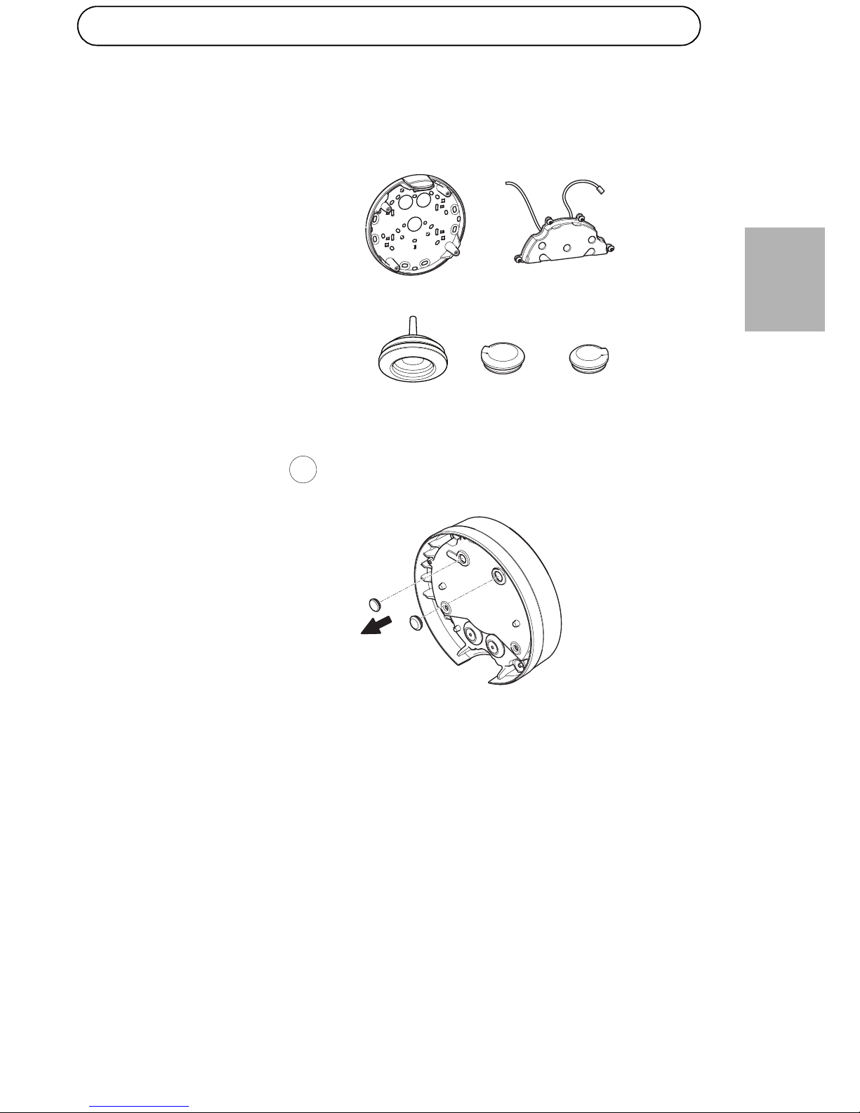
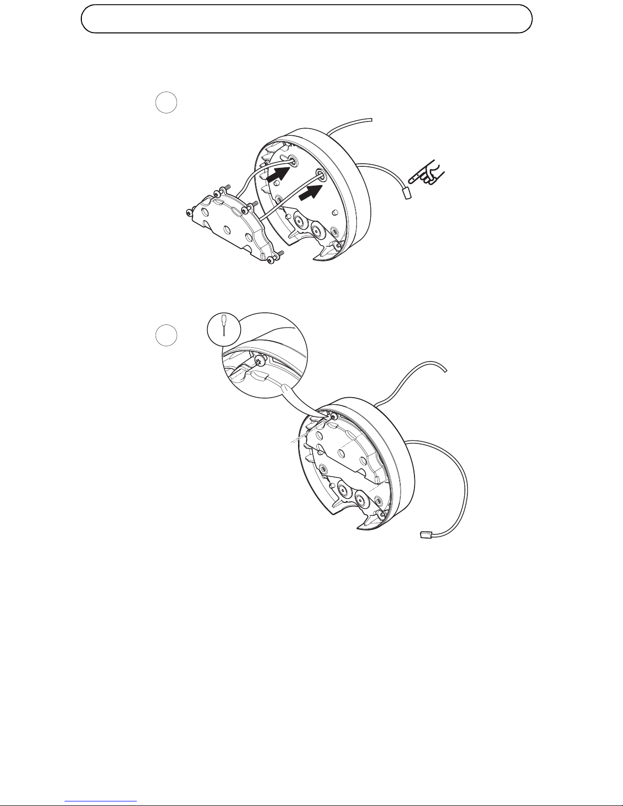
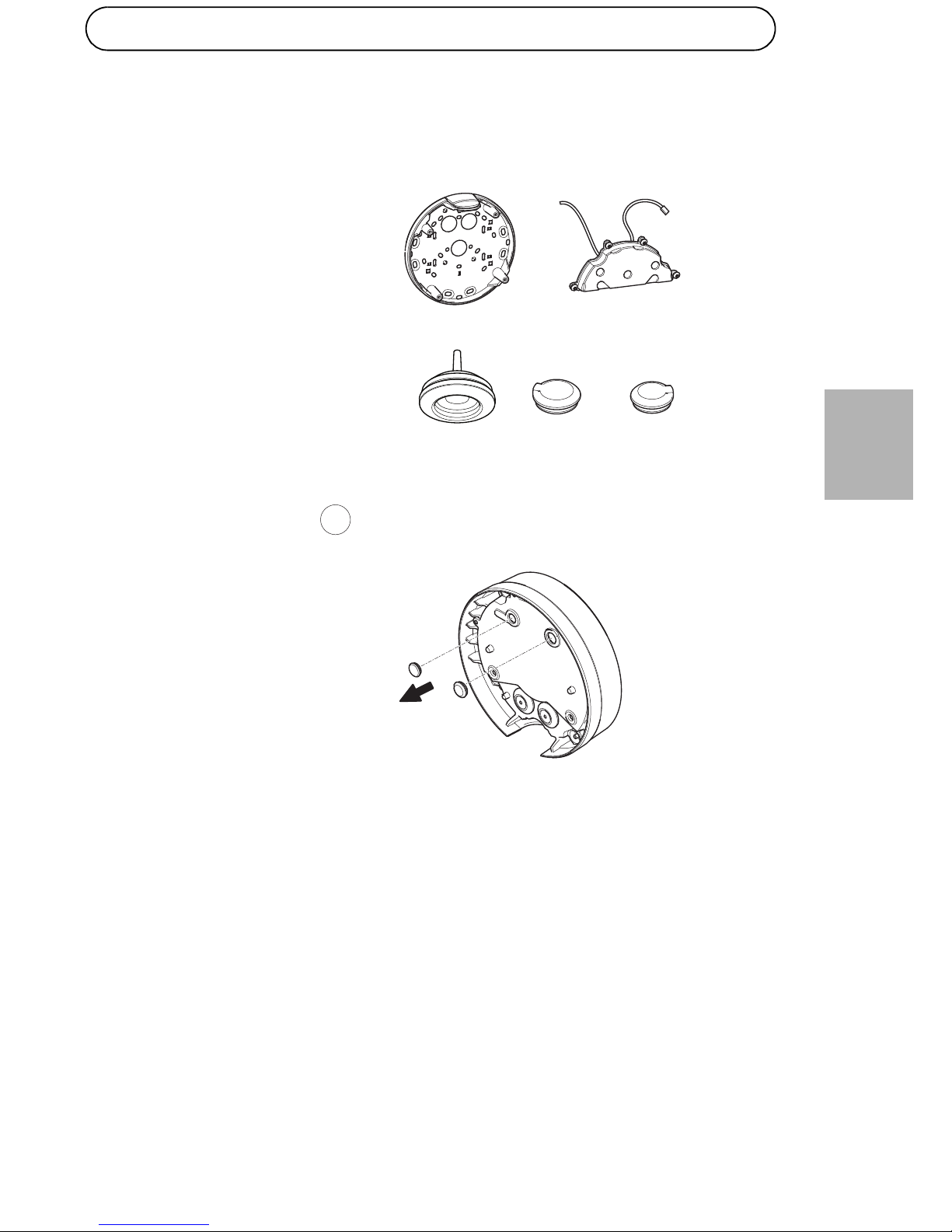
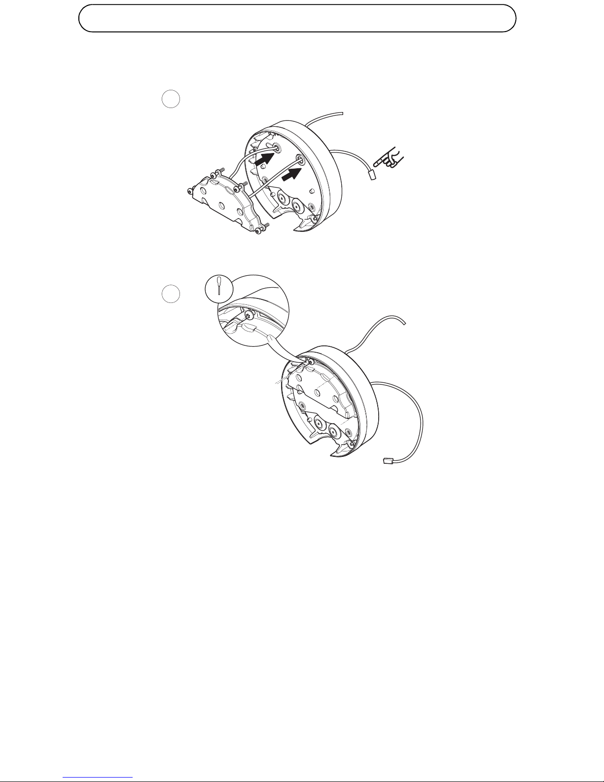
Separate the mounting bracket from the unit casing and use the
extended mounting bracket.
Remove the two plugs from the holes in the unit casing.
1
1x 1x
1x1x 1x
AXIS Q3505-VE
21.3VA@24 V AC
15W@12 V DC
Power Information
Page 8
Page 8 AXIS T8051 Power Converter AC/DC
Route the two cables in the AC/DC module through the two holes in
back of the unit casing. The cable with the connector goes into the hole
on the right.
Attach the AC/DC module onto the unit casing with the four supplied
screws.
2
3
4x
T20
Page 9
AXIS T8051 Power Converter AC/DC Page 9
ENGLISH
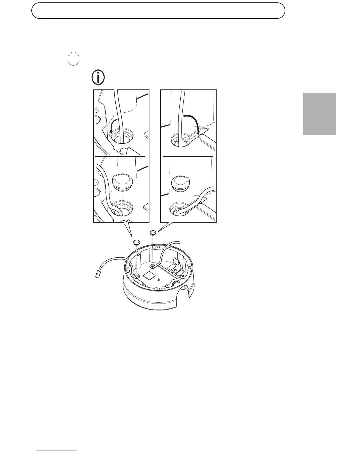
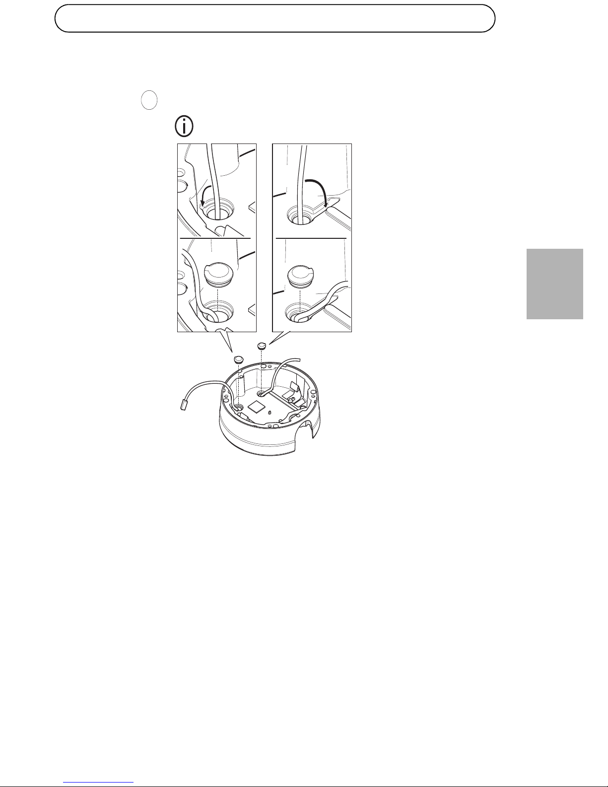
Draw the cables along the grooves and press the supplied cable guides in
the holes to keep them in place.
4
Page 10
Page 10 AXIS T8051 Power Converter AC/DC
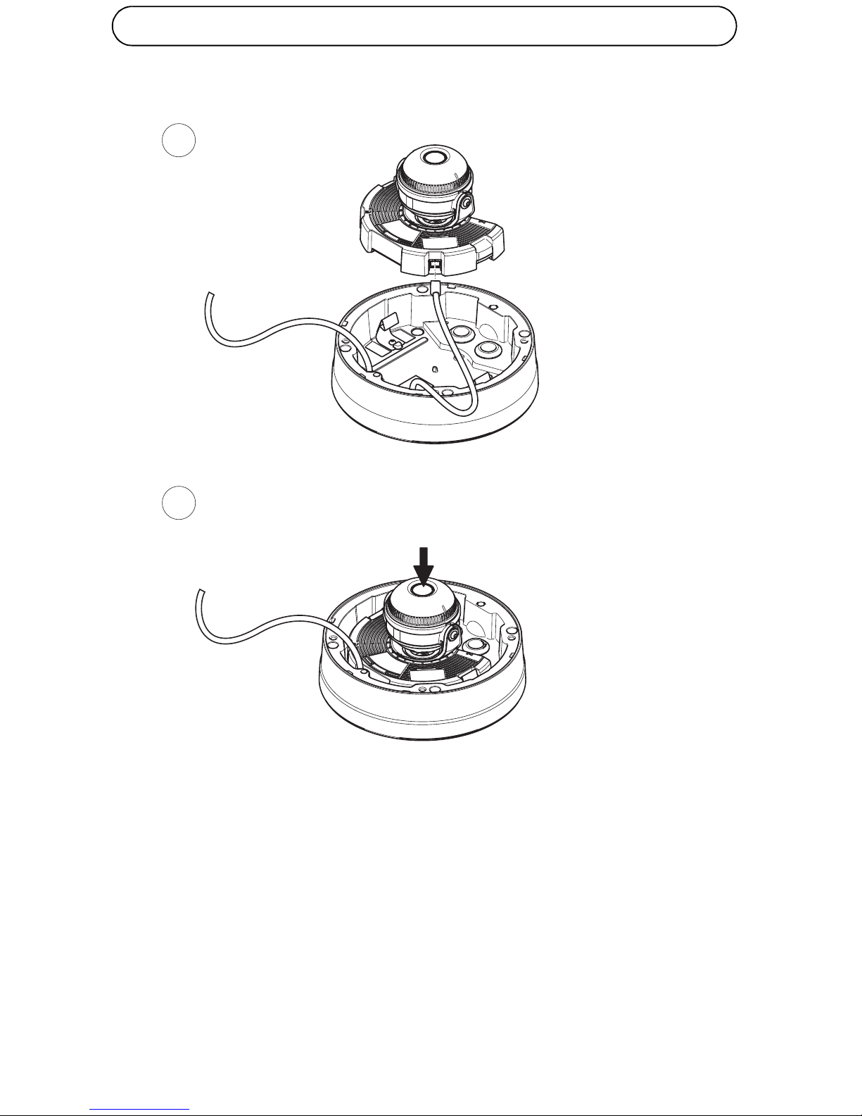
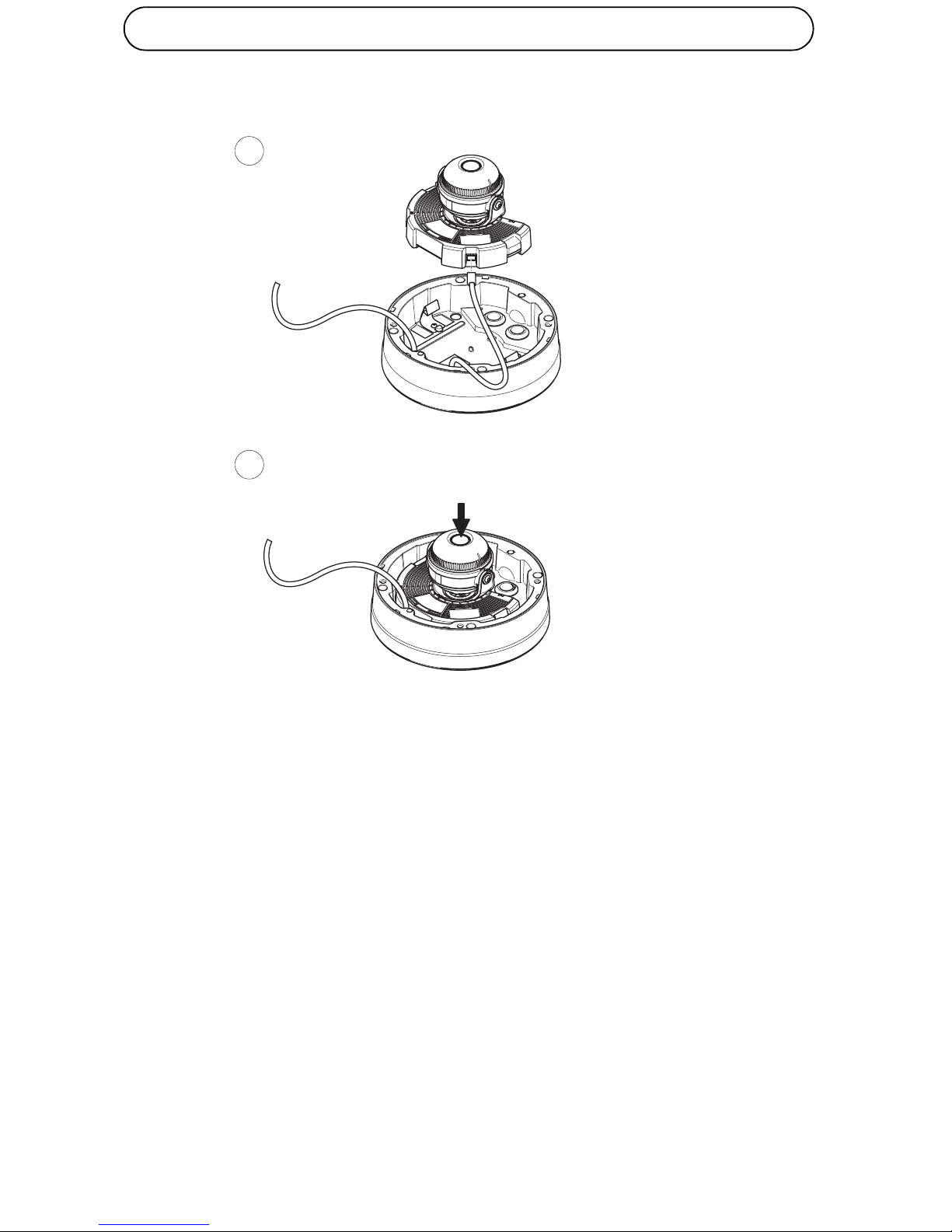
Connect the DC cable to the power connector in the camera unit. Attach
the camera to the unit casing.
5
6
Page 11
AXIS T8051 Power Converter AC/DC Page 11
ENGLISH
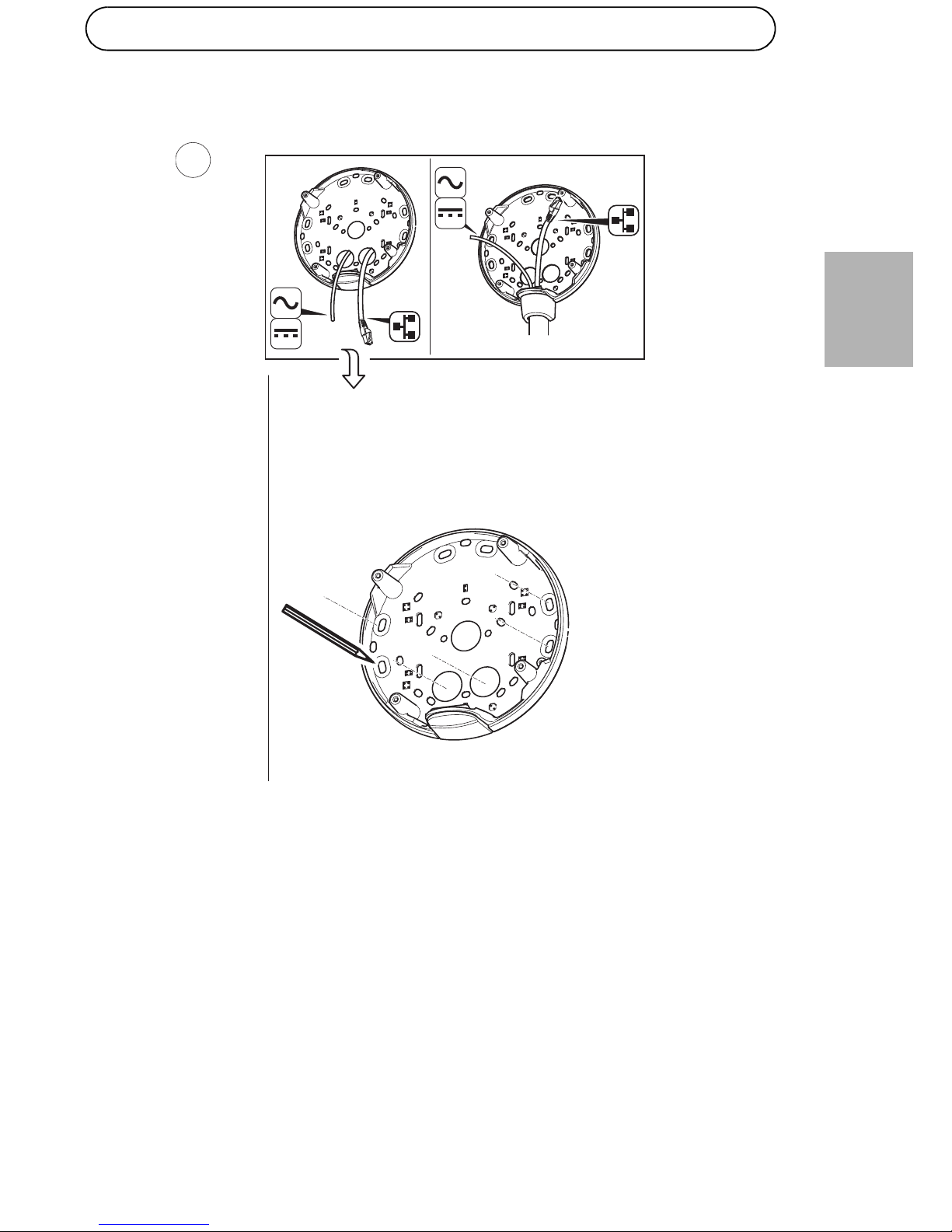
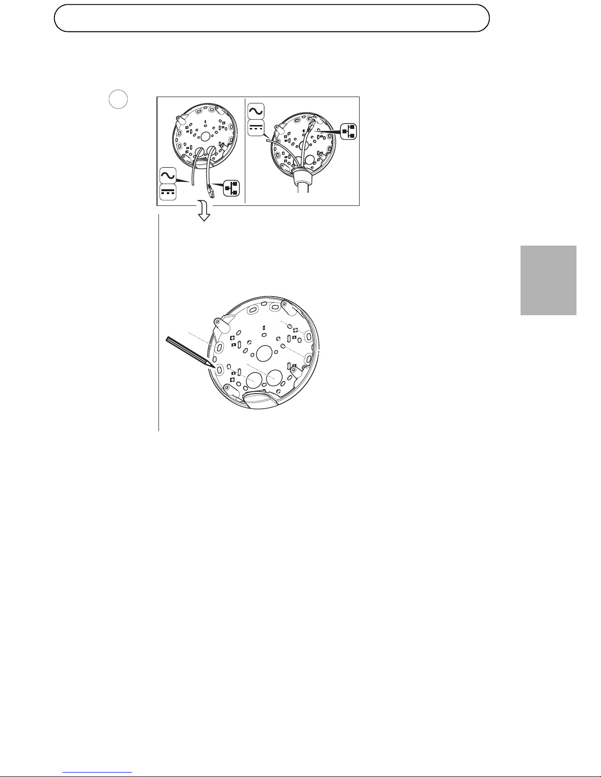
Using the drill template mark the holes for attaching the mounting
bracket on the wall.
7
Page 12

Page 12 AXIS T8051 Power Converter AC/DC
Drill holes for attaching the mounting bracket to the wall, and holes for
cables if cables are to be drawn through the wall.
8
9
Page 13

AXIS T8051 Power Converter AC/DC Page 13
ENGLISH
Draw the cables through the hole or holes in the mounting bracket and
through the gaskets in the unit casing.
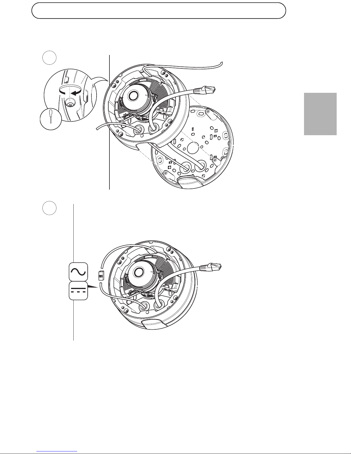
Connect the AC/DC cables coming from the wall and from the AC/DC
module according to the table below.
Wires Specifications
Red + DC or AC
Black – DC or AC
10
11
Page 14
Page 14 AXIS T8051 Power Converter AC/DC
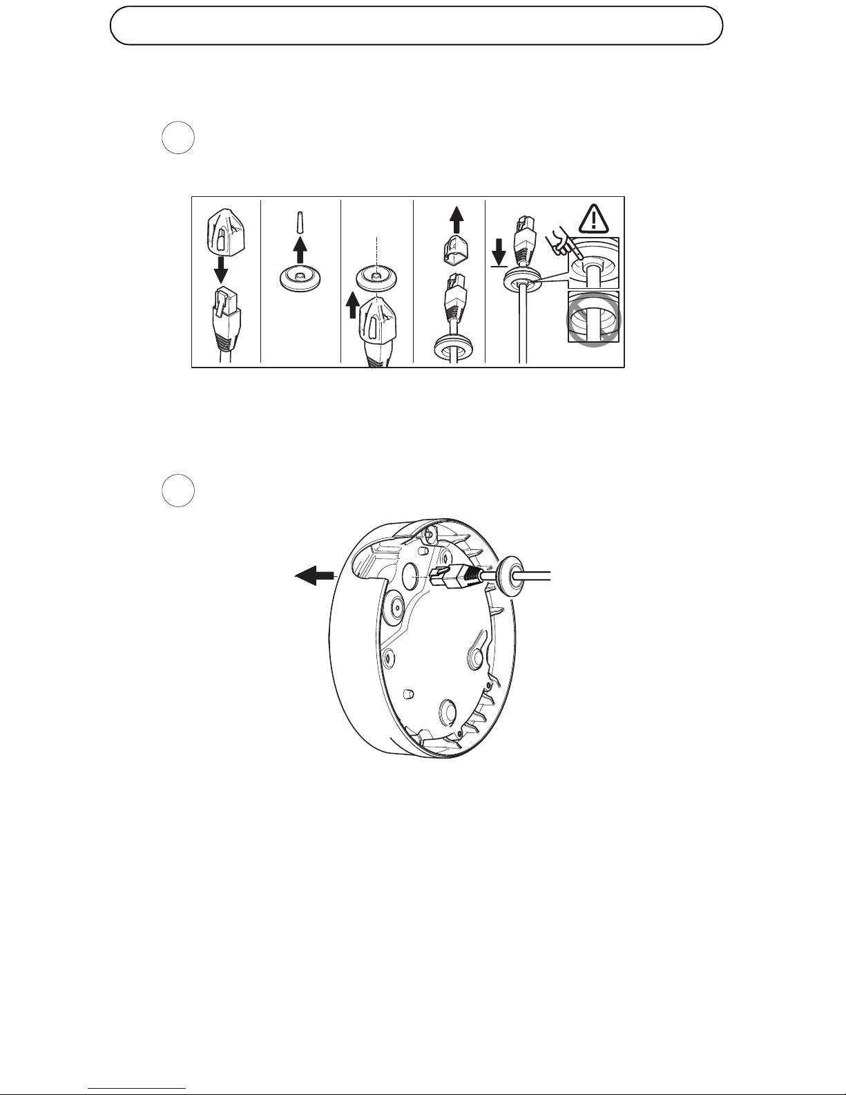
Push the network cable through the black cable gasket in one of the
holes in the unit casing, using the connector guard provided. Pull the
network cable back slightly so that the cable gasket adjusts itself on the
cable.
12
13
Page 15
AXIS T8051 Power Converter AC/DC Page 15
ENGLISH
Draw the AC/DC cable through the 3mm cable gasket. Connect the AC/
DC cable to the power connector.
14
15
4x
T20
Page 16
Page 16 AXIS T8051 Power Converter AC/DC
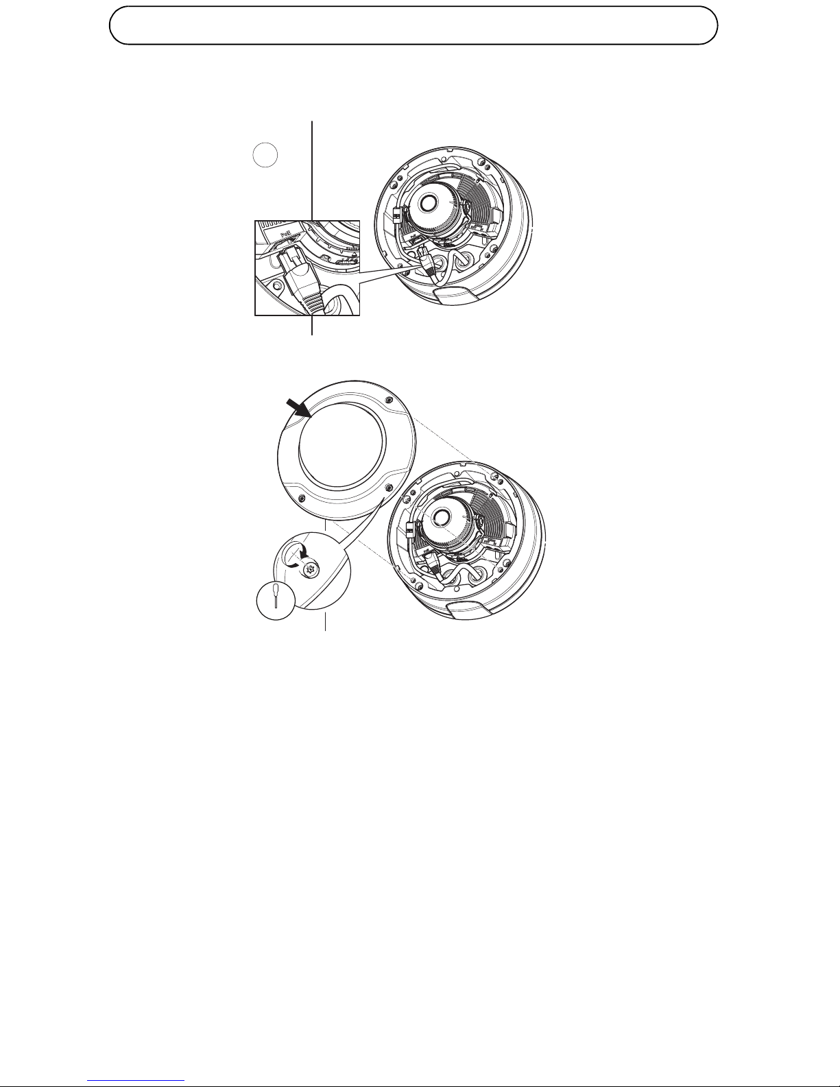
Connect the network cable to the camera and put the dome cover in
place.
4x
T20
16
Page 17
Convertisseur électrique CA/CC AXIS T8051 Page 17
FRAN
Ç
AIS
Remarque :
Pour plus d'informations concernant la caméra réseau et ses pièces,
reportez-vous à son guide d’installation.
Séparez le support de montage du boîtier de l’unité et utilisez le support
de montage rallongé.
Retirez les deux caches obturant les trous du boîtier de l’unité.
1
1x 1x
1x1x 1x
AXIS Q3505-VE
21,3 VA à 24 V CA
15 W à 12 V CC
Informations sur l'alimentation
Page 18
Page 18 Convertisseur électrique CA/CC AXIS T8051
Faites passer les deux câbles dans le module CA/CC par les deux trous
situés à l'arrière du boîtier de l’unité. Le câble équipé du connecteur
passe par le trou situé à droite.
Fixez le module CA/CC au boîtier de l’unité à l'aide des quatre vis
fournies.
2
3
4x
T20
Page 19
Convertisseur électrique CA/CC AXIS T8051 Page 19
FRAN
Ç
AIS
Faites passer les câbles dans les rainures et appuyez sur les guides de
câbles fournis pour les maintenir en place dans les trous.
4
Page 20
Page 20 Convertisseur électrique CA/CC AXIS T8051
Connectez le câble CC au connecteur d'alimentation de la caméra. Fixez
la caméra au boîtier de l'unité.
5
6
Page 21
Convertisseur électrique CA/CC AXIS T8051 Page 21
FRAN
Ç
AIS
À l'aide du gabarit de perçage, marquez les trous destinés à fixer le
support de montage au mur.
7
Page 22

Page 22 Convertisseur électrique CA/CC AXIS T8051
Percez les trous pour fixer le support au mur, ainsi que les trous
permettant le passage des câbles si ceux-ci doivent passer à travers le
mur.
8
9
Page 23

Convertisseur électrique CA/CC AXIS T8051 Page 23
FRAN
Ç
AIS
Faites passer les câbles via le ou les trous du support de montage et à
travers les joints du boîtier de l'unité.
Branchez les câbles CA/CC sortant du mur et du module CA/CC selon le
tableau ci-dessous.
Câbles Caractéristiques
Rouge + CC ou CA
Noir – CC ou CA
10
11
Page 24

Page 24 Convertisseur électrique CA/CC AXIS T8051
Acheminez le câble réseau et le joint du câble noir à travers les trous du
boîtier de l'unité à l'aide du connecteur fourni. Tirez légèrement sur le
câble réseau pour que le joint s'ajuste.
12
13
Page 25

Convertisseur électrique CA/CC AXIS T8051 Page 25
FRAN
Ç
AIS
Faites glisser le câble CA/CC à travers le joint de câble de 3 mm.
Connectez le câble CA/CC au connecteur d'alimentation.
14
15
4x
T20
Page 26

Page 26 Convertisseur électrique CA/CC AXIS T8051
Branchez le câble réseau à la caméra et mettez le couvercle du dôme en
place.
4x
T20
16
Page 27

AXIS T8051 Umrichter (Wechselstrom/Gleichstrom) Seite 27
DEUTSCH
Hinweis:
Weitere Informationen zu der Netzwerk-Kamera und entsprechenden
Teilen finden Sie in der Installationsanleitung der Kamera.
Nehmen Sie die Montagehalterung vom Kameragehäuse ab, und
verwenden Sie die verlängerte Montagehalterung.
Entfernen Sie die beiden Stopfen aus den Bohrungen im Kameragehäuse.
1
1x 1x
1x1x 1x
AXIS Q3505-VE
21,3 VA bei 24 V AC
15 W bis 12 V DC
Leistungsdaten
Page 28

Seite 28 AXIS T8051 Umrichter (Wechselstrom/Gleichstrom)
Führen Sie die beiden Kabel des Wechselstrom-/Gleichstrom-Moduls
durch die beiden Bohrungen auf der Rückseite des Kameragehäuses. Das
Kabel mit dem Stecker wird dabei durch die rechte Bohrung geführt.
Befestigen Sie das Wechselstrom-/Gleichstrom-Modul mithilfe der vier
mitgelieferten Schrauben am Kameragehäuse.
2
3
4x
T20
Page 29

AXIS T8051 Umrichter (Wechselstrom/Gleichstrom) Seite 29
DEUTSCH
Verlegen Sie die Kabel in den Nuten, und setzen Sie die mitgelieferten
Kabelführungen in die Bohrungen ein, um die Kabel zu fixieren.
4
Page 30

Seite 30 AXIS T8051 Umrichter (Wechselstrom/Gleichstrom)
Schließen Sie das Gleichstromkabel an den Stromanschluss in der
Kameraeinheit an. Bringen Sie die Kamera am Kameragehäuse an.
5
6
Page 31

AXIS T8051 Umrichter (Wechselstrom/Gleichstrom) Seite 31
DEUTSCH
Markieren Sie die Bohrungen zum Befestigen der Montagehalterung an
der Wand mithilfe der Bohrschablone.
7
Page 32

Seite 32 AXIS T8051 Umrichter (Wechselstrom/Gleichstrom)
Bohren Sie die Löcher zum Befestigen der Montagehalterung an der
Wand sowie Löcher für Kabel, wenn diese durch die Wand gezogen
werden sollen.
8
9
Page 33

AXIS T8051 Umrichter (Wechselstrom/Gleichstrom) Seite 33
DEUTSCH
Ziehen Sie die Kabel durch die Bohrung bzw. die Bohrungen in der
Montagehalterung und durch die Dichtungen im Kameragehäuse.
Schließen Sie die Wechselstrom-/Gleichstrom-Kabel von der Wand und
vom Wechselstrom-/Gleichstrom-Modul gemäß der folgenden Tabelle
an.
Leitungen Technische Daten
Rot Gleichstrom (+) oder Wechselstrom
Schwarz – Gleichstrom oder Wechselstrom
10
11
Page 34

Seite 34 AXIS T8051 Umrichter (Wechselstrom/Gleichstrom)
Führen Sie das Netzwerkkabel mithilfe des mitgelieferten
Anschlussstücks durch die schwarze Kabeldichtung in einer der
Bohrungen am Kameragehäuse. Ziehen Sie das Netzwerkkabel ein wenig
zurück, bis die Kabeldichtung bündig um das Kabel sitzt.
12
13
Page 35

AXIS T8051 Umrichter (Wechselstrom/Gleichstrom) Seite 35
DEUTSCH
Ziehen Sie das Wechselstrom-/Gleichstromkabel durch die 3-mmKabeldichtung. Verbinden Sie das Wechselstrom-/Gleichstromkabel mit
dem Stromanschluss.
14
15
4x
T20
Page 36

Seite 36 AXIS T8051 Umrichter (Wechselstrom/Gleichstrom)
Schließen Sie das Netzwerkkabel an der Kamera an, und setzen Sie die
Kuppelabdeckung auf.
4x
T20
16
Page 37

Convertitore di alimentazione CA/CC AXIS T8051 Pagina 37
ITALIANO
Nota:
Per ulteriori informazioni sulla telecamera di rete e sulle sue parti,
consultare la guida all'installazione della telecamera.
Separare la staffa di montaggio dal casing dell'unità e utilizzare la staffa
di montaggio estesa.
Rimuovere i tasselli dai fori del casing dell'unità.
1
1x 1x
1x1x 1x
AXIS Q3505-VE
21,3 VA@24 V CA
15 W@12 V DC
Informazioni sull'alimentazione
Page 38

Pagina 38 Convertitore di alimentazione CA/CC AXIS T8051
Far passare i due cavi nel modulo CA/CC attraverso i due fori sul retro del
casing dell'unità. Il cavo con il connettore va nel foro sulla destra.
Fissare il modulo CA/CC sul casting dell'unità con le quattro viti fornite.
2
3
4x
T20
Page 39

Convertitore di alimentazione CA/CC AXIS T8051 Pagina 39
ITALIANO
Far passare i cavi lungo le scanalature e premere le guide fornite nei fori
per mantenere i cavi in posizione.
4
Page 40

Pagina 40 Convertitore di alimentazione CA/CC AXIS T8051
Collegare il cavo CC al connettore di alimentazione sull'unità
telecamera. Collegare la telecamera al casing dell'unità.
5
6
Page 41

Convertitore di alimentazione CA/CC AXIS T8051 Pagina 41
ITALIANO
Utilizzando la maschera di foratura, contrassegnare i fori per fissare la
staffa di montaggio alla parete.
7
Page 42

Pagina 42 Convertitore di alimentazione CA/CC AXIS T8051
Creare i fori per fissare la staffa di montaggio sulla parete e i fori per i
cavi se i cavi devono passare attraverso la parete.
8
9
Page 43

Convertitore di alimentazione CA/CC AXIS T8051 Pagina 43
ITALIANO
Far passare i cavi attraverso i fori sulla staffa di montaggio e attraverso
le guarnizioni nel casing dell'unità.
Collegare i cavi CA/CC che escono dalla parete e dal modulo CA/CC
secondo quanto riportato nella tabella seguente.
Cavi Specifiche
Rosso + CC o CA
nero - CC o CA
10
11
Page 44

Pagina 44 Convertitore di alimentazione CA/CC AXIS T8051
Premere il cavo di rete attraverso la relativa guarnizione nera in uno dei
fori del casing dell'unità utilizzando l'alloggiamento fornito. Tirare
delicatamente il cavo di rete in modo da adattare la guarnizione al cavo.
12
13
Page 45

Convertitore di alimentazione CA/CC AXIS T8051 Pagina 45
ITALIANO
Far passare il cavo CA/CC attraverso la guarnizione per cavi da 3 mm.
Collegare il cavo CA/CC al connettore di alimentazione.
14
15
4x
T20
Page 46

Pagina 46 Convertitore di alimentazione CA/CC AXIS T8051
Collegare il cavo di rete alla telecamera e riposizionare la copertura della
cupola.
4x
T20
16
Page 47

Convertidor de alimentación de CA/CC AXIS T8051 Página 47
ESPAÑOL
Nota:
Para obtener más información sobre la cámara de red y sus piezas,
consulte la Guía de instalación de la cámara.
Separe el soporte de montaje de la carcasa de la unidad y utilice el
soporte de montaje ampliado.
Quite los dos tapones de los orificios de la carcasa de la unidad.
1
1x 1x
1x1x 1x
AXIS Q3505-VE
21,3 VA a 24 V CA
15 W a 12 V CC
Información de alimentación
Page 48

Página 48 Convertidor de alimentación de CA/CC AXIS T8051
Haga pasar los dos cables del módulo de CA/CC a través de los dos
orificios de la parte posterior de la carcasa de la unidad. El cable con el
conector debe pasar por el orificio de la derecha.
Fije el módulo de CA/CC a la carcasa de la unidad con los cuatro tornillos
suministrados.
2
3
4x
T20
Page 49

Convertidor de alimentación de CA/CC AXIS T8051 Página 49
ESPAÑOL
Disponga los cables a lo largo de las muescas y presione las guías de
cables suministradas en los orificios para que los cables no se muevan de
su sitio.
4
Page 50

Página 50 Convertidor de alimentación de CA/CC AXIS T8051
Conecte el cable de CC al conector de alimentación de la unidad de la
cámara. Fije la cámara a la carcasa de la unidad.
5
6
Page 51

Convertidor de alimentación de CA/CC AXIS T8051 Página 51
ESPAÑOL
Utilice la plantilla de perforado para marcar los orificios para fijar el
soporte de montaje a la pared.
7
Page 52

Página 52 Convertidor de alimentación de CA/CC AXIS T8051
Perfore los orificios para fijar el soporte de montaje a la pared, así como
los orificios para los cables si los cables van a atravesar la pared.
8
9
Page 53

Convertidor de alimentación de CA/CC AXIS T8051 Página 53
ESPAÑOL
Pase los cables a través del orificio u orificios del soporte de montaje y a
través de las juntas de la carcasa de la unidad.
Conecte los cables de CA/CC que vienen de la pared y del módulo de CA/
CC según la siguiente tabla.
Cables Especificaciones
Rojo + CC o CA
Negro – CC o CA
10
11
Page 54

Página 54 Convertidor de alimentación de CA/CC AXIS T8051
Empuje el cable de red a través de la junta de cable negra de uno de los
orificios de la carcasa de la unidad, usando el protector del conector
facilitado. Tire del cable de red hacia atrás suavemente de manera que la
junta de cable se ajuste en el cable.
12
13
Page 55

Convertidor de alimentación de CA/CC AXIS T8051 Página 55
ESPAÑOL
Pase el cable de CA/CC a través de la junta de cable de 3 mm. Conecte el
cable de CC/CA al conector de alimentación.
14
15
4x
T20
Page 56

Página 56 Convertidor de alimentación de CA/CC AXIS T8051
Conecte el cable de red a la cámara y coloque en su sitio la cubierta del
domo.
4x
T20
16
Page 57

AXIS T8051 電力コンバータ AC/DC 57
日本語
注意 :
ネットワークカメラとその部品の詳細については、カメラのイ
ンス トールガイドを参照してください。
ユニットケーシングから取り付けブラケットを外し、拡張取り付け
ブラケットを使用します。
ユニットケーシングの穴から 2 つのプラグを取り外します。
1
1x 1x
1x1x 1x
AXIS Q3505-VE
21.3 VA@24 V AC
15 W@12 V DC
電源について
Page 58

58 AXIS T8051 電力コンバータ AC/DC
AC/DC モジュールの 2 本のケーブルを、ユニットケーシングの裏
の 2 つの穴に通します。その際、コネクタの付いたケーブルを右側
の穴に通します。
付属のネジ 4 本を使用して、AC/DC モジュールをユニットケーシ
ングに取り付けます。
2
3
4x
T20
Page 59

AXIS T8051 電力コンバータ AC/DC 59
日本語
ケーブルを溝にはめ込み、付属のケーブルガイドを穴に押し込んで
ケーブルを固定します。
4
Page 60

60 AXIS T8051 電力コンバータ AC/DC
DC ケーブルをカメラユニットの電源コネクタに接続します。カメ
ラをユニットケーシングに取り付けます。
5
6
Page 61

AXIS T8051 電力コンバータ AC/DC 61
日本語
取り付けブラケットの取り付け穴の位置を、ドリルテンプレートを
使用して壁面に印を付けます。
7
Page 62

62 AXIS T8051 電力コンバータ AC/DC
ドリルを使用して、取り付けブラケットの取り付け穴を開けます。
壁を通してケーブルを配線する場合は、ケーブル用の穴も開けます。
8
9
Page 63

AXIS T8051 電力コンバータ AC/DC 63
日本語
ケーブルを取り付けブラケットの穴に通し、さらに、ユニットケー
シングのガスケットに通します。
以下の表に従って、壁面および AC/DC モジュールからの AC/DC
ケーブルを接続します。
ワイヤー 仕様
赤 + DC または AC
黒 - DC または AC
10
11
Page 64

64 AXIS T8051 電力コンバータ AC/DC
付属のコネクタガードを使用して、ユニットケーシングの孔の 1 つ
に、黒いケーブルガスケットを通してネットワークケーブルを押し
込みます。ネットワークケーブルを少し手前に引き、ケーブルガス
ケットをケーブルにぴったりと合わせます。
12
13
Page 65

AXIS T8051 電力コンバータ AC/DC 65
日本語
AC/DC ケーブルを 3mm ケーブルガスケットに通します。AC/DC
ケーブルを電源コネクタに接続します。
14
15
4x
T20
Page 66

66 AXIS T8051 電力コンバータ AC/DC
ネットワークケーブルをカメラに接続し、ドームカバーを取り付け
ます。
4x
T20
16
Page 67

Page 68

Installation Guide Ver.1.2
AXIS T8051 Power Converter AC/DC Printed: March 2015
© Axis Communications AB, 2014-2015 Part No. 63062
 Loading...