

Page 1
SE-01 INDICATOR
Engineering documentation
File DTR-SE01-039-06-09 B-42 GB
Page 2

2 ENGINEERING DOCUMENTATION
_____________________________________________________________________________________________
Contents:
1 General information ................................................................................................... 3
2 Certificates ................................................................................................................. 3
3 Completeness ............................................................................................................ 3
4 Keys and indicators ................................................................................................... 4
5 Security rules ............................................................................................................. 5
6 Technical data ........................................................................................................... 6
7 Preparations .............................................................................................................. 8
7.1 Comunication interfaces ....................................................................................... 11
7.2 Transmitter interface ............................................................................................. 11
7.3 External key interfaces ......................................................................................... 12
7.4 Strip for connecting external devices .................................................................... 14
8 General Rules ......................................................................................................... 15
9 Indicator cooperation with other systems................................................................. 15
10 Cooperation with computer or printer.................................................................... 16
11 Basic functions ..................................................................................................... 19
11.1 Normal weighing ................................................................................................ 19
11.2 Weighing with tare ............................................................................................. 20
11.3 Increased readibility ........................................................................................... 20
12 Special functions .................................................................................................. 21
12.1 Menu customization function (ACtIV and dEFAUL) ........................................... 22
12.2 Autozeroing function (AutoZE) .......................................................................... 23
12.3 Pieces counting (PCS) ...................................................................................... 24
12.4 Printer cooperation settings (PrInt) ................................................................... 25
12.5 Serial port parameters setting (Port) ................................................................. 26
12.6 Constant tare (tArE) ........................................................................................... 27
12.7 Average calculation function (AVErAG) ............................................................ 29
12.8 Recipe weighing function (RECIPE) ................................................................. 30
12.9 Percentage weighing function (PErC) ............................................................... 31
12.10 Anti-disturbance filter function (FILtEr) .......................................................... 32
12.11 Function for maximum value indication (UP) .................................................. 33
12.12 Force measuring function (nEWto) ................................................................ 34
12.13 Function for weighing large animals (LOC) ..................................................... 35
12.14 Checkweighing function (thr) .......................................................................... 36
12.15 Total weight function (totAL) ........................................................................... 39
12.16 Function for setting date and time (dAtE) ....................................................... 41
12.17 Function for selecting label number (LAbEL) .................................................. 42
12.18 External calibration (CALIb) ............................................................................ 43
12.19 Setting time of stabilization function (Stb) ....................................................... 44
12.20 Entering reference zero function (Zero) .......................................................... 45
12.21 Automatic switching off the scale function (AutoOF)....................................... 46
12.22 Density determining function (dEnSIt) ............................................................ 47
12.23 Calculator for good packaging control (tP) ...................................................... 49
12.24 Statistical calculations function (StAt) ............................................................. 53
12.25 Paperweight calculation (PAP) ....................................................................... 55
13 Maintenance and troubleshooting ......................................................................... 56
Declaration of Conformity ................................................................................................ 57
Page 3

ENGINEERING DOCUMENTATION 3
_____________________________________________________________________________________________
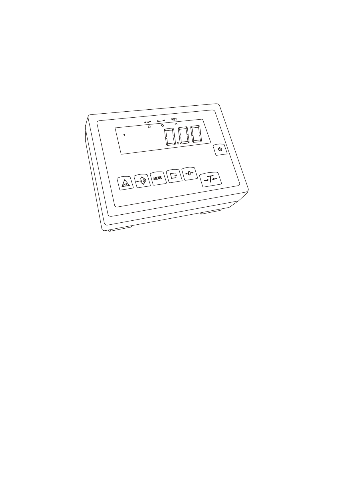
1 General information
The Se-01 meter is the ready subassembly, designed for single- or double-range
balances, using the extensometer force sensors.
The meter is used in few types, differing in housing structure and displays size:
- SE-01/A/18 – OSA aluminium housing, powder coated, displays 18 mm (LED)
or 14 mm (LCD)
- SE-01/N/18 – OSN stainless steel housings, hermetic (IP65), displays 18 mm
(LED) or 14 mm (LCD)
- SE-01/N/25 – ODN stainless steel housing, hermetic (IP65), displays 25 mm
(LED) or 14 mm (LCD)
As a standard, the SE-01/A/18 is a subassembly of platform B series balances, the
SE-01/N/18 – of stainless and hermetic balances, the SE-01/N/25 – of platform 4B
balances produced by AXIS.
Each meter has the set of special functions: automatic zeroing, pieces counting,
comparing with threshold values, etc., which may be available for the user or not –
according to the order.
In the further manual part the SE-01 meter operation is described, as the part of
complete balance.
2 Certificates
Test certificate of SE-01 indicator (No PL CB 1) was issued by Main Office for
Measurements in Warsaw (Notified Body No 1440).
SE-01/N/18(25) indicators are of IP65 protection class, confirmed with the
research carried out by The Research Laboratory of The Electrotechnology
Institute in Gdańsk, accredited by Polish Centre for Accreditation.
The indicator may be used as a base for scales conforming EN 45501 Metrological
aspects of non-automatic weighing instruments harmonized with the Council
Directive 90/384/EEC amended with 93/68/EEC.
NACE Classification: 29.24.23.
3 Completeness
A standard set consists of:
1. SE-01 indicator
2. Ferrit TN/20/10/7-3C90– 1 pcs
3. Ferrit TN/16/9,6/6,3-3E27 – 2 pcs
4. RS232C connector (option with RS232C, indicator SE-01/N/18 and 25)
5. SE-01 indicator engineering documentation
6. Guarantee card
7. Mounting guide (on demand)
Page 4
4 ENGINEERING DOCUMENTATION
→T←
→0←
→0←
_____________________________________________________________________________________________
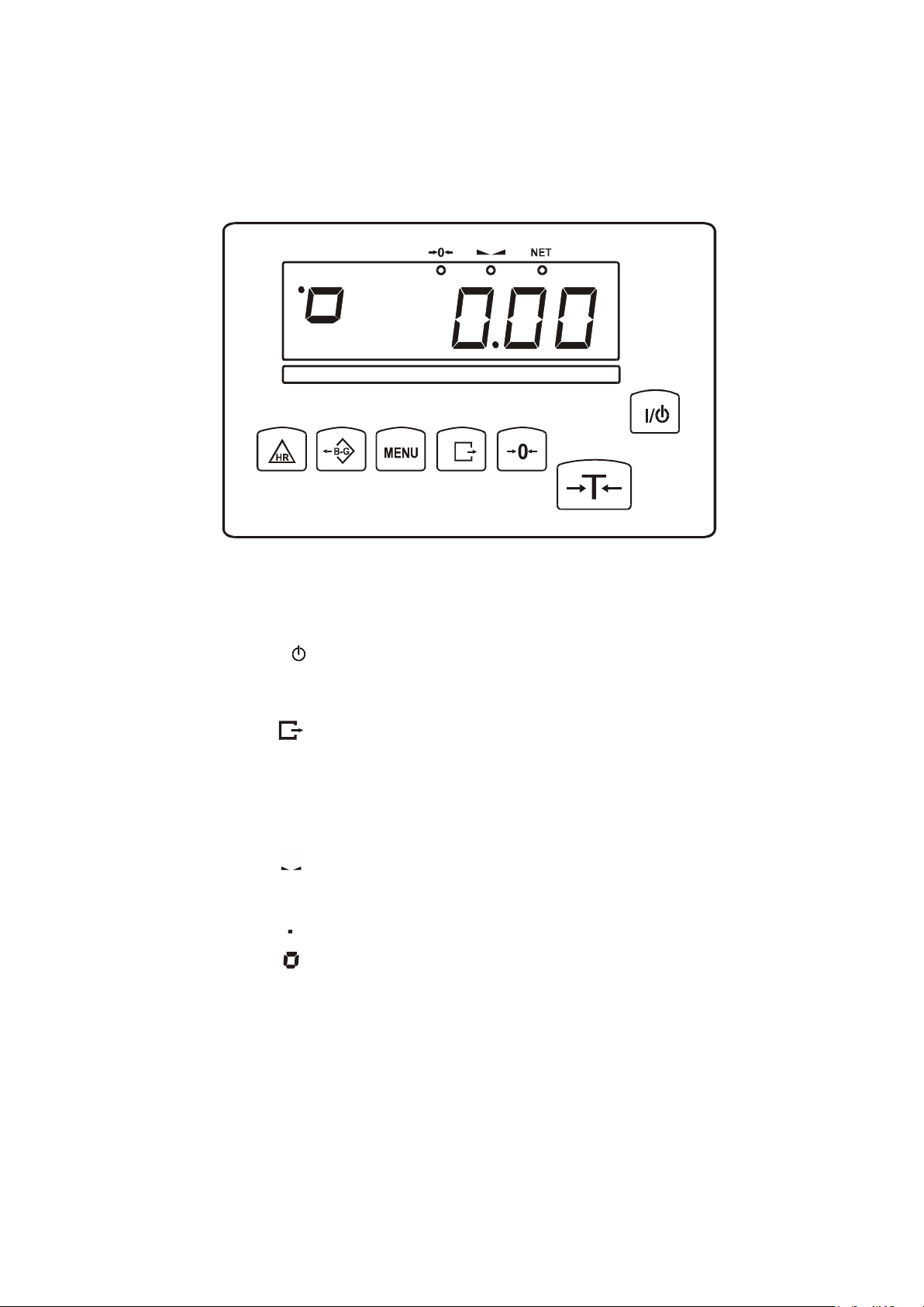
4 Keys and indicators
key
I/
key
key
key
key
key
key
MENU
B/G
HR
indicator
indicator
indicator
NET
indicator
indicator
indicator
bar indicator
MODE - special function setting,
indicator OFF - standby,
indicator
indicator
B/G - gross mass (key B/G),
pcs - pieces counting
- switch-on / switch-off (standby),
- tare (subtract package weight from weighed mass),
- zeroing (when the platform is empty),
- result printout,
- special function menu,
- gross,
- high resolution,
- zero indicator,
- result stabilization indicator,
- net weight indicator (indication with subtracted tare)
- gross mass (after use of B/G key),
- indicator of pieces counting (indications in pieces)
LCD option:
- total load indicator (graduated 0-100%)
Max, Min, d, e, III - metrological parameters and accuracy class.
Page 5
ENGINEERING DOCUMENTATION 5
_____________________________________________________________________________________________
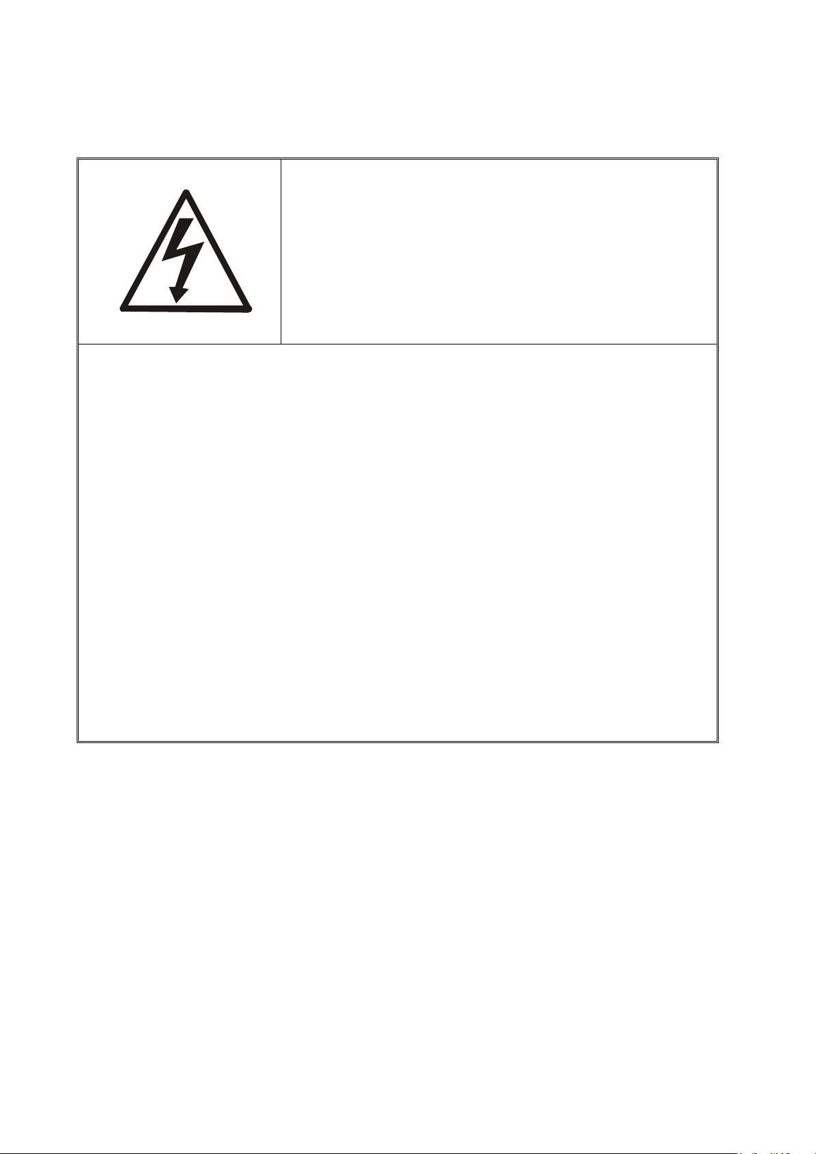
5 Security rules
1. All repairs and necessary regulations can be made by authorized
personnel only.
To avoid electrical shock or damage of a scale or
connected peripheral devices, it is necessary to
follow the security rules below.
2. To avoid fire risk use a feeder of an appropriate type (supplied with a
scale). Pay attention that supply voltage is compatible with specified
technical data.
3. Do not use a scale when its cover is opened.
4. Do not use a scale in explosive conditions.
5. Do not use a scale in high humidity.
6. If a scale seems not to operate properly, plug it out of the mains and do
not use it until checked by authorized service.
Page 6
6 ENGINEERING DOCUMENTATION
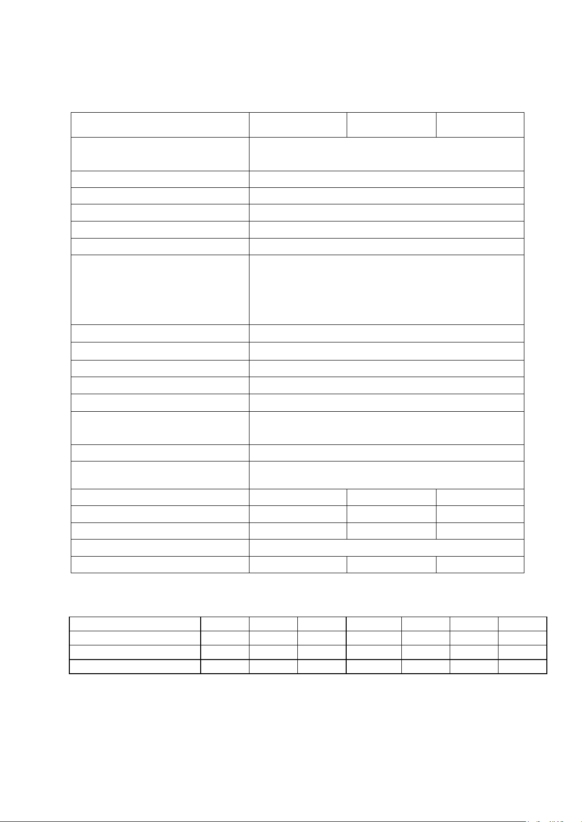
Max verification units number
6000e
Part of error(pi)
0,5
Accuracy class
III
1, 2, 5, 10, 20 (g. dkg, kg)
free
Tare range
full
Input signal range
Working tem
perature
Max sensor number
6szt.
Sensor excitation
5V AC 25Hz
Sensor impedance range(RL)
Sensor connecting
system 4 or 6
-
line for sensor
Maximal cable length (l/S)
75m/mm
Opto
-
isolator output load capacity
100mA, 24V
Casing option
OSA
OSN
ODN
Dimensions
190x140x70mm
200x146x77mm
238x182x77mm
Casing security level (IP)
-
IP65
IP65
Power supply
230V, 50Hz, 6VA
Weight
1,8kg
2,3kg
2,3kg
Maximum
load (Max2/Max1)
15/6kg
30/15kg
60/30kg
120/60kg
150/60kg
200/60kg
Minimum load
40g
100g
200g
400kg
400g
400g
1kg
Readability (d2/d1))
5/2g
10/5g
20/10g
50/20g
50/20g
100/50g
100/50g
Verification units
5/2g
10/5g
20/10g
50/20g
50/20g
50/20g
100/50g
_____________________________________________________________________________________________
6 Technical data
Parameter SE-01/A SE-01/N/18 SE-01/N/25
(3000e/range - in multi range scale)
Readability (d)
Verification unit (e)
2,4÷9,5mV (option 10mV)
4,8÷19mV (option 20mV)
9,6÷38mV (option 40mV)
19,2÷72mV (option 80mV)
Minimal input signal (∆Umin/e) 0,4µV/e
-10÷40oC
40÷4000Ω
system 6- line for sensor
(option)
The available ranges of double-range balances:
2
300/150kg
(e2/e1)
Page 7
ENGINEERING DOCUMENTATION 7
Fixing
_____________________________________________________________________________________________
The metrological parameters of the balance are indicated on the rating plate.
Installation
Installation system
SE-01/A
2 holes Ф5,
spacing 59mm
SE-01/N/18 SE-01/N/25
2 holes Ф5,
spacing 6.30in
2 holes Ф5,
spacing 7.99in
Page 8
8 ENGINEERING DOCUMENTATION
Before connecting the sensors to the indicator unplug the device from the
Supply unit
sensor protecting
wire - 2 coil turns
_____________________________________________________________________________________________
7 Preparations
1. To build a scale basing on SE-01 indicator contact authorized manufacturer
service point or use Installation Guide delivered with the indicator.
2. The manufacturer gives a full guaranty for SE-01 indictor only when the
indicator was mounted by AXIS Sp. z o.o. In other cases the guaranty obligation
is taken over by the final contractor of the weighing device.
mains to avoid damaging the indicator!
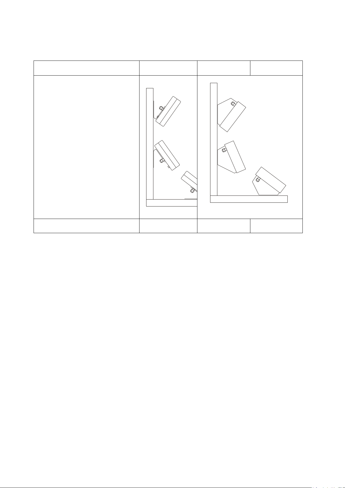
To comply CE marking requirements, for connecting the wires use filtering cores
delivered with the indicator, appropriate for signal type: sensor(s) wires – φ20mm
core, protecting wires - φ16mm (see the diagram below). The cores should be
placed within 30mm from the place of its connection.
Electric diagram SE-01/A:
mains protecting
wire 2 coil turns
Main board
h
t
g
n
e
l
.
n
i
m
signal wires - 4 coil turns
cramps
When 6-wires connection of strain gauge transducers is used (REF+ and REF-)
jumpers shown on the picture above should be soldered out from the main board.
Page 9
ENGINEERING DOCUMENTATION 9
All devices should be powered from the same line (phase) 230V.
wire - 2 coil turns
m
i
n
.
l
e
n
g
t
h
_____________________________________________________________________________________________
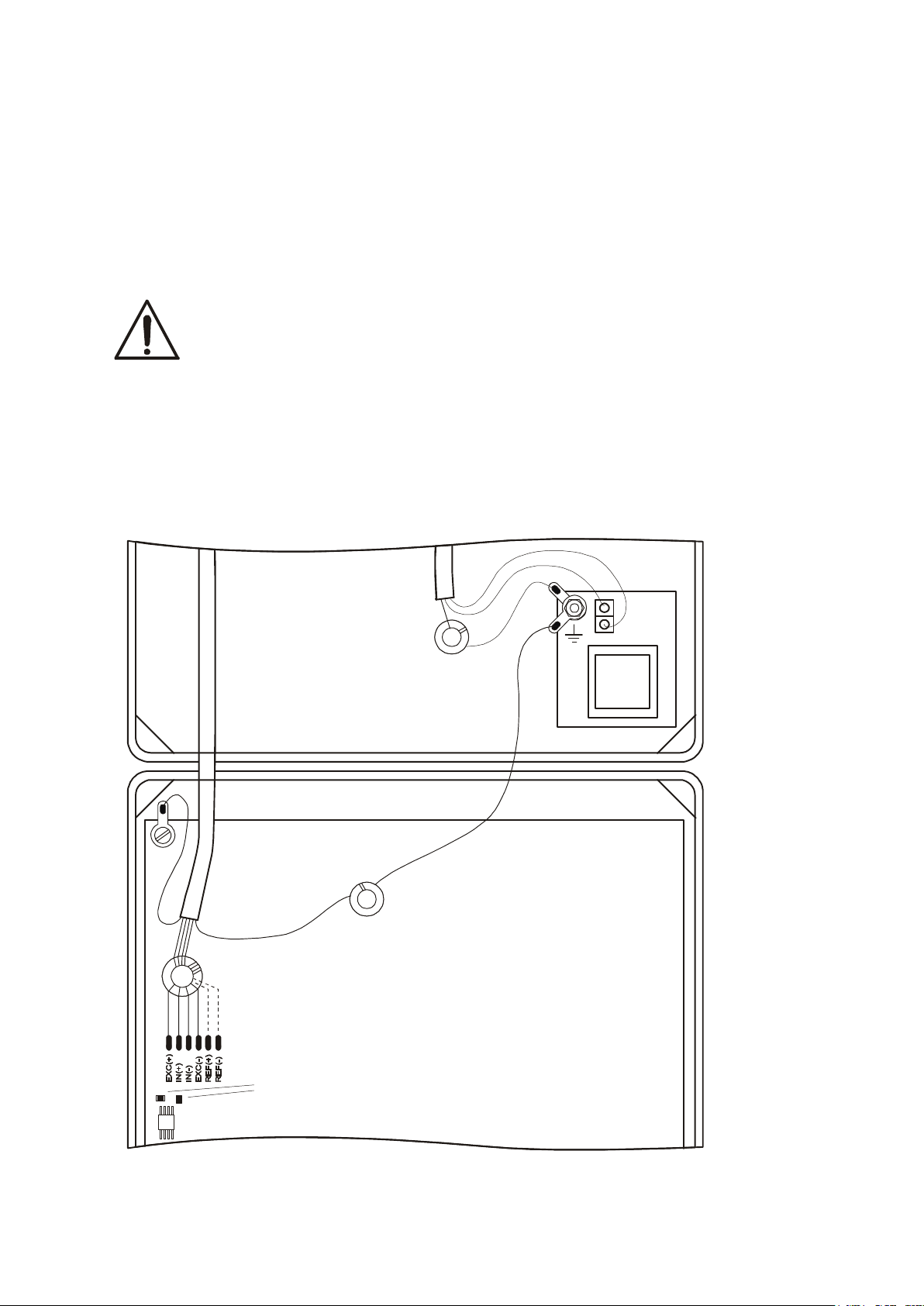
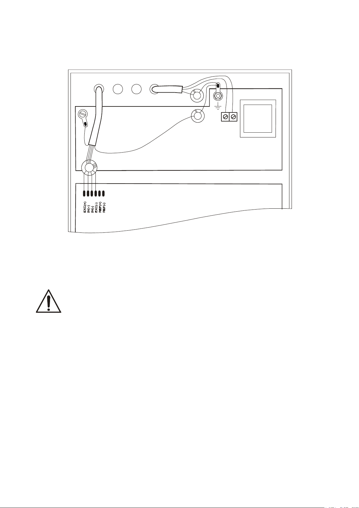
Electric diagram SE-01/N/18 and SE-01/N/25:
shield
mains protecting
wire 2 coil turns
sensor protecting
signal wires - 4 coil turns
1. Connect the external devices cables to the meter sockets, or in the SE-01/N/..
meters to the board strip inside the meter, using the hermetic penetrations in the
housing (the SE-01/N.. strip drawing is shown below).
To feed the scale use only mains socket with ground contact.
Page 10
10 ENGINEERING DOCUMENTATION
~230V
50Hz
_____________________________________________________________________________________________
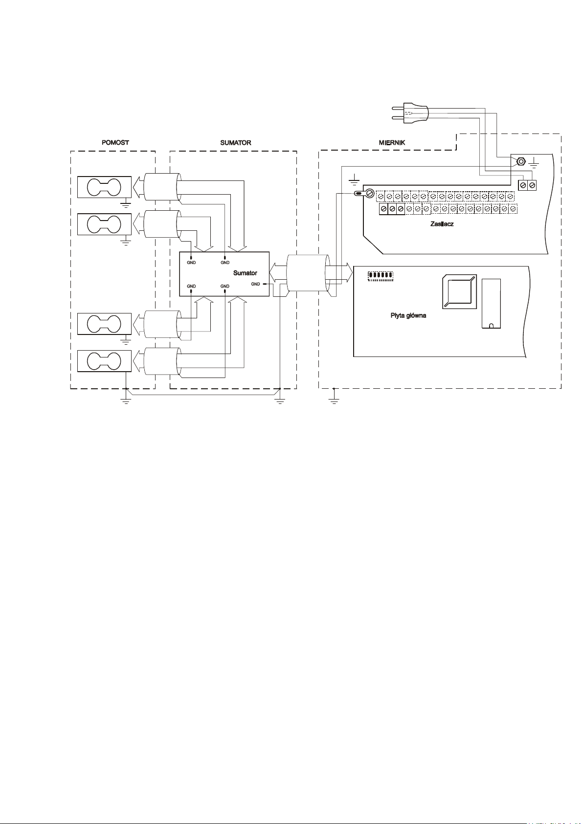
Diagram of common wires and shields in the platform balances:
Caution:
The galvanic connection of sensors and adder housing is necessary.
Page 11
ENGINEERING DOCUMENTATION 11
RS232C
AA
A
OUT
casing
shield
_____________________________________________________________________________________________
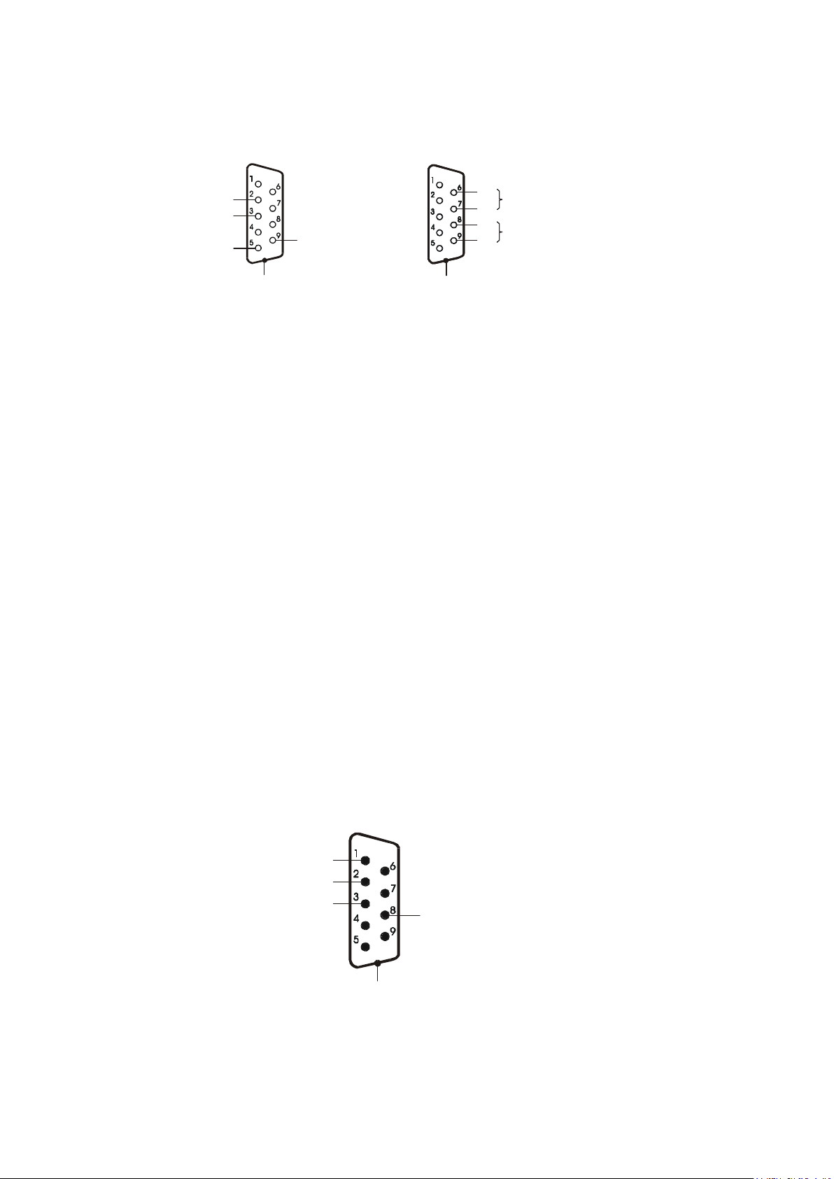
7.1 Comunication interfaces
RS485
RxD ( rec eive)
TxD ( trans mit)
casing
+5V(option)
DE-9
gnd
IN
BB
B
DE-9
In SE-01/A/18 indicator an interface is placed on indicator’s housing. In SE01/N/... indicators interfaces are ends of wires which go out from an indicator.
Attention:
1.
To connect scale’s wire with RS232C interface (described above) to a
computer, RS232C adapter should be used which is included as the equipment of
SE-01/N/18 and SE-01/N/25 indicators (electric diagram of RS232C adapter is the
same as WK-1 wire).
2. In case of using the scanner, the RS232C port is divided into two separate
connectors. Receiver and 5V power supply are for the scanner, and transmitter for
the computer.
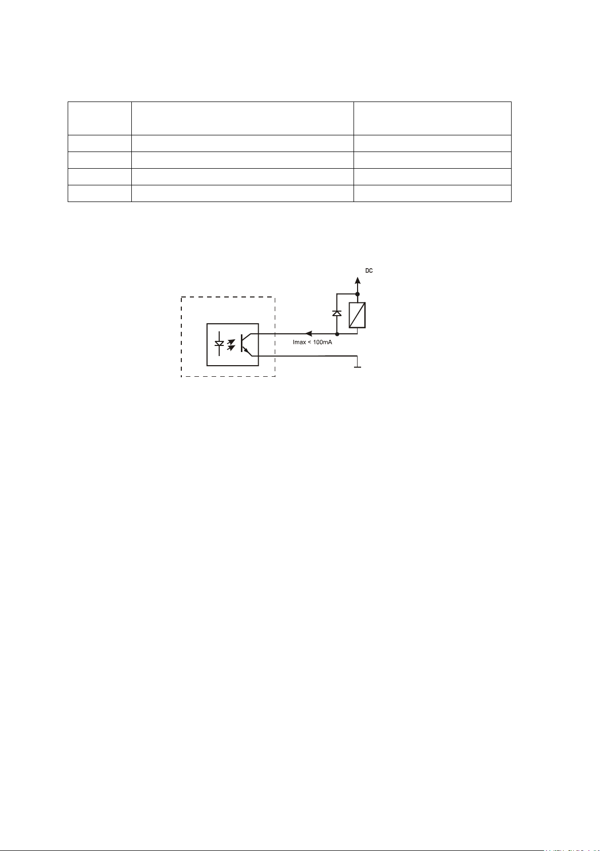
7.2 Transmitter interface
P1-P3 (THRESHOLDS) outputs are used to connect dosing or signaling (option)
devices. There are opto-isolators of an open collector type with 100mA / 24V
maximum load. They can be connected directly to transmitters inputs or to
MS3K/P board offered by AXIS separately or in ST 3K/P control box (3
transmitters, own power supply).
In SE-01/A/18 indicator THRESHOLD interface is placed on indicator’s housing.
P1 (pr óg I)
P1 (threshold I)
P2 (threshold II)
P2 (pr óg II)
P3 (zero)
P3 (zero)
GND
Page 12
12 ENGINEERING DOCUMENTATION
+24V
Scale
Relay
_____________________________________________________________________________________________
In SE-01/N/... indicators outer wires have digital markers.
Marker
Signal Wire color*
No.
1 P1 (I threshold) green
2 P2 (II threshold) white
3 P3 (zero) brown
10 GND (indicator ground) black or yellow
* colors can be changed
Diagram for direct connect a transmitter to THRESHOLD output:
1
8
0V
* in option without an interface – 10 is in the place of 8
Outputs are adapted for direct connect RM96P transmitter of DC24V input voltage
and AC250V 8A output. Transmitter’s coil has to be secured with diode e.g.
1N4148.
It is recommended to use MS 3K/P electronic board (3 transmitters of RM96P
type – max. load of 3A/250V) or complete ST 3K/P control (feeder, 3 transmitters
like above).
The way THRESHOLD outputs work is described in the separate document
(Special functions description).
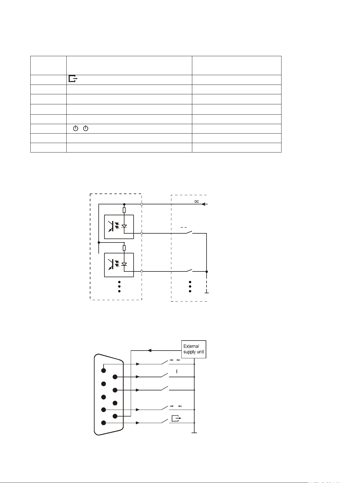
7.3 External key interfaces
The input of external keys allows to place (make double) selected scale keys into
control box or operator’s workstation. As a standard the input is taken out with a
wire for direct connect to a control panel. SE-01/A/18 indicators can be equipped
with external key interfaces (as an option on demand).
External keys require external 24V DC feeder, which ensure galvanic isolation of
a scale from automatic systems.
Page 13
ENGINEERING DOCUMENTATION 13
→0←
→T←
+24V
T (T/ON)
Waga
Obiekt
T
I/O
Scale
Object
_____________________________________________________________________________________________
Marker numbers and outer wires colors of SE-01/N/18 (SE-01/N/25) indicators:
Marker
External keys inputs Wire color*
No.
12
(P)
yellow
13 MENU (F) brown
15
18
(T/ON)
green
white
20 +24V (voltage of external feeder) pink
21 I/ ( ) blue
22 HR red
23 B/G violet
* colors can be changed
External keys connecting – standard configuration:
20
18
13
MENU(F)
0V
External keys connecting – the option with an interface:
+24V
1
6
2
3
4
5
7
8
9
MENU
0
Page 14
14 ENGINEERING DOCUMENTATION
→0←, →T←
_____________________________________________________________________________________________
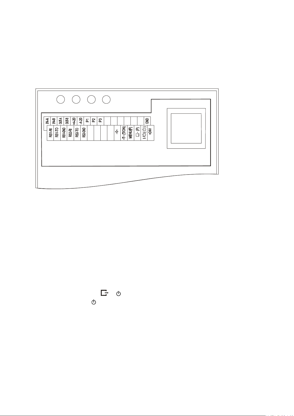
7.4 Strip for connecting external devices
Inside SE-01/N/18 and SE-01/N/25 indicators housing there is a strip with
communication ports, transmitters and external keys connections on it.
The draft of SE-01/N/18 (SE-01/N/25) indicators strip:
Strip description:
IN-A(+), IN-B(-),
- input and output of RS485 interface,
OUT-A(+), OUT-B(-)
+ 4-20 - (+) analog output 4-20mA
(optionally 0-10V or 0-20mA),
- 4-20 - (-) analog output 4-20mA
(optionally 0-10V or 0-20mA),
P1-P3(THRESHOLDS) - opto-isolator outputs for transmitters,
GND - external ground (opto-isolators emitters),
RS1 - RI, TO i GND - main RS232C interface (e.g. for a computer),
RS2 - RI, TO i GND - additional RS232C interface (e.g. for a printer),
, MENU, , I/
- external keys inputs,
→0←, T/ON, F, P,
+24V - an input of external feeder voltage input supplying
opto-isolators.
Page 15
ENGINEERING DOCUMENTATION 15
_____________________________________________________________________________________________
8 General Rules
1. After switching-on the power, the scale proceeds with self-tests and zeroing the
scale. During start-up the scale should not be loaded (does not apply to tank
scales, where scales are not zeroed after start-up).
2. Before each measurement make sure that zero indicator is displayed. If zero
indicator does not displayed or “----“ communicate appears, press →0← key
and wait until zero indication and zero indicator appears.
3. The scale is equipped with a tare equal to its range. To tare the scale press
→T← key. Storing a tare value does not extend measuring range, but only
subtracts it from a load placed on a pan. If the scale is not loaded →T← key
does not operate – to zero the scale press →0← key.
4. Weighing result should be read when the indicator " " lights, which signalizes
stabilization of a result.
5. Weighed sample should be placed in the centre of the platform.
Do not drop weighed objects on the platform!
Do not overload the scale more then 20% of maximum
load (Max).
6. Protect the scale against dust, aggressive dusts and liquids. To clean it is advised
to wash the scale with water and dry it afterwards.
7. Each indicator may be equipped on demand with a set of special functions:
constant tare, total weight and many more.
9 Indicator cooperation with other systems
Opto-isolators outputs of P1-P3 signals (open collector) are destined for external
signaling or dosing devices control. Interface work is controlled by function of
comparing with threshold values (tHr).
Page 16

16 ENGINEERING DOCUMENTATION
_____________________________________________________________________________________________
10 Cooperation with computer or printer
In indicators equipped with one serial RS232C (RS485) interface there are two
possible modes of interface work:
Standard mode
The scale sends weighing result when initial signal form computer appears or
key of the scale is pressed.
Automatic mode (for cooperation with a printer)
Data is sending automatically after a sample is put on and scale indication
becomes stable. Next transmission is possible after sample is taken off. Successive
measurement number and weighing result are sending.
The choice of serial interface work mode is made by use of LPt special function
(see further).
The description of data transmission protocol in standard mode (Long protocol)
A scale sends data with following settings:
Communication parameters: 8 bits, 1 stop bit, no parity, baud rate 4800bps.
Available orders and scale responses:
initialising signal (data send order):
Computer→Scale: S I CR LF (53h 49h 0Dh 0Ah),
Scale→Computer: scale response according to description below (16 bytes),
Description of response bytes:
Byte 1 - sign or space
Byte 2 - space
Byte
3÷4
- digit or space
Byte 5÷9 - digit, decimal point or space
Byte 10 - digit
Byte 11 - space
Byte 12 - k, l, c, p or space
Byte 13 - g, b, t, c or %
Byte 14 - space
Byte 15 - CR
Byte 16 - LF
scale tarring (calling →T← key press):
Computer→Scale: S T CR LF (53h 54h 0Dh 0Ah),
Scale→Computer: without response,
scale turning on / off (calling
I/
key press):
Computer→ Scale: S S CR LF (53h 53h 0Dh 0Ah),
Page 17

ENGINEERING DOCUMENTATION 17
_____________________________________________________________________________________________
Scale →Computer: without response,
scale zeroing (calling →0← key press):
Computer→ Scale: S Z CR LF (53h 5Ah 0Dh 0Ah),
Scale →Computer: without response,
entering to special function menu (calling MENU key press):
Computer→ Scale: S F CR LF (53h 46h 0Dh 0Ah),
Scale →Computer: without response,
setting low threshold value:
Computer→ Scale: S L D1...DN CR LF (53h 4Ch D1...DN 0Dh 0Ah)
D1...DN – threshold value, maximum 8 characters („-” – negative value, digits,
dot – decimal separator), number of digits after dot should be the same as on
scale display,
Scale →Computer: without response,
Example:
⋅ in order to set low threshold 1000g in scale B1.5 (d=0.5g) the following order
should be sent:
S L 1 0 0 0 . 0 CR LF (53h 4Ch 31h 30h 30h 30h 2Eh 30h 0Dh 0Ah),
⋅ in order to set low threshold 100kg in scale B150 (d=50g) the following order
should be sent:
S L 1 0 0 . 0 0 CR LF (53h 4Ch 31h 30h 30h 2Eh 30h 30h 0Dh 0Ah),
setting high threshold value:
Computer→ Scale: S H D1...DN CR LF (53h 48h D1...DN 0Dh 0Ah),
D1...DN – threshold value (see )
Scale →Computer: without response.
Note:
Network number different than zero (F..-rS / nr function) changes scale working
mode: communication with a computer is possible after logging the scale in with
02h scale_number command. To log the scale out use 03h command.
The description of data transmission protocol in automatic mode
Every time weighing is done in the moment when indications becomes stable the
scale sends successive three-digit number (counter value) and result of the
weighing. If an indication is zero there is no transmission from the scale.
Weighing counter is cleared after each choosing of automatic mode (see further –
LPt function).
The sequence of sending values is the following:
Page 18
18 ENGINEERING DOCUMENTATION
Scale
Scale
Printer
_____________________________________________________________________________________________
1. Three digits of successive measurement number(digits are sending in order
form highest to lowest).
2. Two space characters separating a number from scale indication.
3. Scale indication (as in LONG protocol).
Scanner operation method description (option)
Each time, when the scanner sends the 16-character record, containing the
operator name or code, preceded with the EOT (04H) prefix.
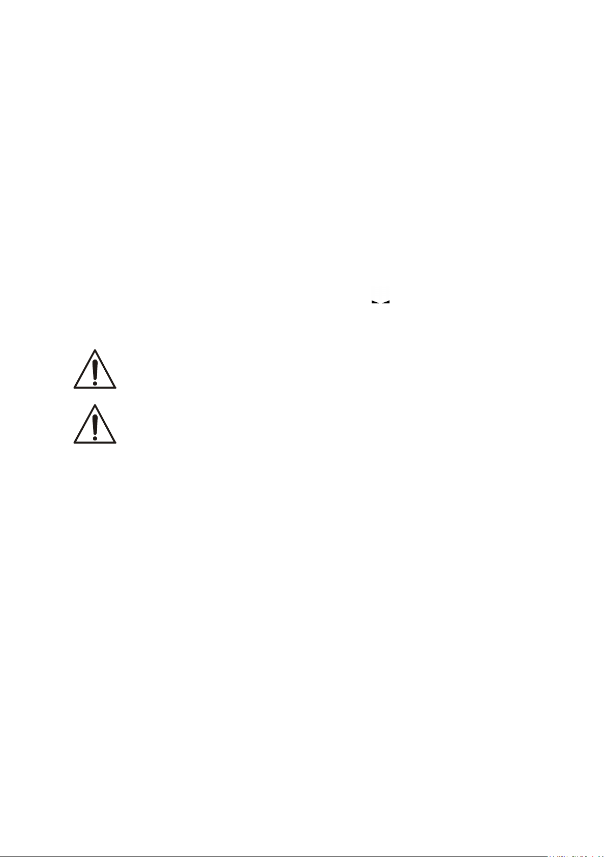
Connecting cable WK-1 (scale – computer / 9-pin):
Computer
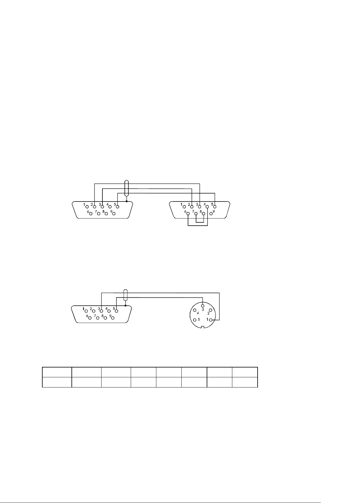
Connecting cable WD-1 (scale – Kafka printer):
Internal switches settings of KAFKA printer:
SW-1 SW-2 SW-3 SW-4 SW-5 SW-6 SW-7 SW-8
on off on off off on off off
AXIS offers computer programs for cooperation with scales which description and
demo versions are available on www.axis.pl website. Furthermore a free
program for testing of scale serial interface is also placed there.
Page 19

ENGINEERING DOCUMENTATION 19
0.00
2.30
0
2.30
T
_____________________________________________________________________________________________
11 Basic functions
To make clear how to manage with each function, in further part of instruction
descriptions are replaced with pictures.
- put a load on the pan
- remove the load from the pan
- press the key when indication is
displayed
- forced change
- automatic change
11.1 Normal weighing
Press
legalized scales), which zeros the
scale, operates only when the pan is
empty .
Weighing result should be read when
→0←
key (→T← key in non-
the indicator " " lights.
Page 20

20 ENGINEERING DOCUMENTATION
2.30
T
NET
NET
2.30
2.30
_____________________________________________________________________________________________
11.2 Weighing with tare
The scale is equipped with tare equal
to its range.
Joint value tare and mass net can not
0.00
cross a maximum of scale.
To display gross weight press B/G
key.
40.01
Note:
Press B/G key to return to net weight
indication.
42.31
11.3 Increased readibility
Press HR key to display the weighing
result (for 5s.) with the highest
readability possible. This function is
especially helpful in scales with legal
verification with d=e.
2.29
The weighing result with increased
readability can be used for
informational purposes only and
cannot be printed or sent to a
computer with key.
Page 21

ENGINEERING DOCUMENTATION 21
_____________________________________________________________________________________________
12 Special functions
List of available functions:
menu customization function (ACtIV),
removal of all function from menu (dEFAUL).
autozeroing function (AutoZE),
pieces counting function (PCS),
function for setting serial port working (PrInt)
function for setting serial port (Port)
entering tare function (tArE)
recipe weighing function (rECIPE),
weighing large animals function (LOC)
force measuring function (nEWto)
maximum value indication function (UP)
anti-disturbance filter function (FILtEr)
average calculating function (AVErA)
percentage weighing function (PErC),
extended calibration function (CALIb)
setting time of stabilisation function (Stb)
selecting label number function (LabEL)
automatic switching off scale function (AutoOF)
entering reference zero (Zero)
determining solids and liquids density function (dEnSIt)
calculator for good packaging control (tP) - option*
statistical calculations (StAt)- option*
paperweight calculation function (PAP) - option*
function with additional equipment require:
options with the clock:
- setting current date and time function (dAtE)
- total weight function (totAL)
options with the transoptors connectors:
- checkweighing function (thr)
* Functions offered with special version of scale software (with limited possibility
of using other special functions).
User create own menu by choosing function in ACtIV function (described in
chapter 14.1).
Page 22

22 ENGINEERING DOCUMENTATION
0.00
ACtIV
T
T
T
_____________________________________________________________________________________________
12.1 Menu customization function (ACtIV and dEFAUL)
Among available user functions it is
possible to select these, which should be
displayed after pressing MENU key. It
allows avoiding displaying whole list of
available functions, which makes
operation time longer.
Operation sequence shown in the
.
PCS
Port
Port -0
Port -1
.
.
pictures on the left causes adding
function for setting serial interface
RS232C parameters (Port) to function
menu.
After switching on ACTIV function a
dot is displayed on the right side (to
distinguish from regular menu). Chosen
functions are displayed with a dot on
the left side.
In every moment, it is possible to
restore primary (manufacture) settings
choosing dEFAULt special function.
In order to remove function from menu
in the last operation in place of selecting
Port -1 choose Port -0.
Page 23

ENGINEERING DOCUMENTATION 23
0.01
AutoZE
T
T
_____________________________________________________________________________________________
12.2 Autozeroing function (AutoZE)
When F..-Aut function is activated,
the scale automatically ensures stable
zero indication if the pan is empty or
if zero indication was acquired by
pressing →T← key.
To leave the function press MENU
key, then with →T← key chose
AutoZE and Aut-0.
Aut-0
Note:
Autozeroing function is activated
automatically for 10 min. after
Aut-1
switching-on.
0.00
Page 24

24 ENGINEERING DOCUMENTATION
0
0.00
23.40
PCS -0
PCS - --
T
T
T
T
_____________________________________________________________________________________________
12.3 Pieces counting (PCS)
This function enables to count
identical pieces, e.g. turnbuckles or
buttons.
A measurement is performed in two
phases:
5
- first phase - single piece weight
calculation on the basis of defined
pieces amount (5, 10, 20, 50, 100,
200 or 500 pieces),
- second phase – pieces counting.
PCS
It is advised that single piece weight
is not less than one reading unit and
sample weight used in first phase is
bigger than 100 reading units.
12
PCS-1
5
12
To leave function press MENU key
and then with key chose
PCS and PCS-0.
Note:
1. Err-3 communicate signalises that
a sample was not put on the pan.
The same communicate appears
if single piece weight is less than one
reading unit (it is possible to count
pieces but measuring error is
bigger).
2. To chose previously used pieces
amount select " _ _ " in first phase
(in case no value was chosen, error
communicate appears
3. During pieces counting →T← key
function does not change.
4.In scales equipped with LCD
display, weighing unit is visible and
"" sign is replaced with "pcs ".
Page 25

ENGINEERING DOCUMENTATION 25
0.00
PrInt
PrIn-1
PrIn-0
T
T
_____________________________________________________________________________________________
12.4 Printer cooperation settings (PrInt)
Activate the function for automatic
serial port working mode
(cooperation with a printer.
After activation the scale prints
a header. Weighing result with
a successive measurement number is
printed automatically after result
stabilisation (without using key).
To select computer cooperation mode
( key activated and weighing
results without successive numbers)
press MENU key, then with →T←
key chose PrIn-0 and PrIn-1.
0.00
1.05
PrInt
Page 26

26 ENGINEERING DOCUMENTATION
0.00
Port
Port-1
Port-0
-9600
-4800
PArItY
T
T
T
T
T
T
T
T
T
T
_____________________________________________________________________________________________
12.5 Serial port parameters setting (Port)
The function enables to set the
following transmission parameters
(standard parameters underlined:
- transmission protocol (Prot):
LonG - printer,
ELtron – label printer,
- transmission speed (bAud: 1200,
4800, 9600, ...),
- the number of bits in a byte (bit: 7,
8),
- parity control (PArItY: 0, 1; Odd: 0,
1),
- network number when working in
baud
bIt
multistand computer system (when
working as a single scale the value
should be “0”,
- continuous transmission – without
using key, approx. 10 results per
second (SEnd: 0, 1).
Protocol Eltron automaticly activated
function LAbEL.
To set desired transmission
parameters activate Port function,
choose appropriate parameter and
press →T← key to accept needed
parameter value. The example at the
left presents how to set transmission
Odd
Send
speed value to 9600bps.
To leave the function choose out
option.
nr
out
Page 27

ENGINEERING DOCUMENTATION 27
-
1.7
0.00
tArE
tAr -3
T
T
T
NET
...
...
1.70
_____________________________________________________________________________________________
12.6 Constant tare (tArE)
This function enables to measure gross weight of a sample placed in a container of
a known weigh value (stored in the memory) and to display calculated net weight
of the sample. Tare value is recalled from the memory with →0← key when the
pan is empty. Tare value may be entered using the keypad or by sampling
container weight from the pan.
Operation sequence:
The following options are possible:
- tAr-0 – leave the function,
- tAr-1 – activate the function with
the previous tare value,
- tAr-2 – sample tare value from the
pan,
- tAr-3 – enter tare value with keys:
1
1.
1.0
→0←
- tAr-4 – printout a setting value of
tare
If the function is active, NET
indicator is displayed.
Options tAr-1 enables to activate the
function with previous tare value
after leaving the function with tAr-0
option.
Note:
Tare value is stored in memory also
after unplugging the scale from the
mains.
, , →T← and MENU
Page 28

28 ENGINEERING DOCUMENTATION
-1.70
0
B/G
NET
.
_____________________________________________________________________________________________
Weighing with constant tare:
When tAr function is activated, press
→0←
key to zero the indication and
to recall tare value from the memory.
Tare value is displayed with ”-” sign.
10.00
B/G key enables for instant
switching between net and gross
weight.
13.70
Note:
When the pan is empty →T← key
does not operate – to tare the scale
use →0← key.
Page 29

ENGINEERING DOCUMENTATION 29
0.00
0.00
AUErAG
AUEr- 1
MENU
T
T
_____________________________________________________________________________________________
12.7 Average calculation function (AVErAG)
The function allows for calculating average value of performed measurement
series. During series of measurements successive results are registered
automatically when scale indication is stabilised.
Press MENU key and select AUErAG
pressing →T← key.
The following will be shown
successively on display:
- AUEr-0 – leaving function,
- AUEr-1 – measurement with average
calculation..
Select AUEr-1. It will allow weighing
with simultaneous storing results into
summing register for average
calculation
1.00
Measurement registration is performed
automatically in the moment when
scale indication becomes stable. Short
time displaying of „ - - ” denotes that
0.00
load can be taken off and new one can
be put on. Results above scale Min are
registered only. Number of
measurements is limited to 9999.
2.00
In order to read average value key
should be used.
- first pressing causes displaying
number of measurements (n).
- second displaying causes displaying
average value (=).
n
2
- third pressing allows continuing
average calculation.
_
_
1.50
If a printer is connected to scale the
following report will be printed :
0.00
Date: ... Time.
...
MEASUREMENS No = ...
AVERAGE VALUE = ...
In
order to finish calculation press
MENU key, and then select AUEr i
AUEr-0.
Page 30

30 ENGINEERING DOCUMENTATION
_
_
_
_
0.00
rECIPE
rECI- 0
rECI- 1
0.11
0.12
0.13
0.00
0.00
0.36
MENU
T
T
T
T
rECIPE
rECI- 0
MENU
T
T
_____________________________________________________________________________________________
12.8 Recipe weighing function (RECIPE)
This function allows for separate
weighing of several ingredients in
one container with a possibility of
control total weight of all weighed
components.
The function has the following
options:
- rECI-0 – leave the function with
possibility of reading to read total
weight,
- rECI -1 – start recipe weighing
- rECI -2 – continue previous recipe.
When preparing a recipe successive
ingredients (A, B, C, etc.) are
weighed each time starting from zero
indication. In order to allow this after
weighing of each ingredient tare the
scale.
After weighing of several ingredients
reading total weight is possible
(despite scale taring). In order to do
that press MENU key, select rECIPE
function once more and use rECI -0
option.
Sign „
indication. Recipe is finished when
→T←
When „
continuing is possible. rECI -2 option
is used for that.
Note:
Sign „≡” on the left side of display
informs about rECIPE function
activity.
” signals total weight
key is pressed.
” sign is displayed recipe
A+B+C
A
B
C
_
_
_
_
_
_
_
_
_
_
_
_
_
_
_
_
_
Page 31

ENGINEERING DOCUMENTATION 31
_
_
0.00
1.70
PErC
PErC-0
PErC-1
100.00
T
T
_____________________________________________________________________________________________
12.9 Percentage weighing function (PErC)
This function allows displaying
weighing result in percents.
A measurement is performed in two
phases:
- first phase – weighing a reference
100%
sample (100%),
- second phase – measuring specific
sample as a percentage of
the reference sample.
Weighing result is displayed in
different format, depending on the
weight value of reference sample. For
weight values of reference sample
0÷3,5% of weighing range result is
displayed in format 100, for range
3,5÷35% - in format 100.0, and
above 35% - in format 100.00.
„%” sign is replaced with „
”
indicator.
The function has the following
_
_
5%
options:
- PErC-0 – disable the function,
- PErC-1– set current scale indication
_
_
95.00
as 100% and activate percentage
weighing,
- PErC-2 – continue percentage
weighing after exiting to normal
weighing.
Note:
During percentage weighing →T←
key has its normal function.
Page 32

32 ENGINEERING DOCUMENTATION
0.00
0.00
FILtEr
FIL- 0
FIL- 1
FIL- 2
FIL- 4
T
T
_____________________________________________________________________________________________
12.10 Anti-disturbance filter function (FILtEr)
This function allows using digital filter
with selected intensivity during
weighing. Filter reduces the influence
of mechanical vibrations (air blasts,
base vibrations) on measurement result.
Press MENU key and select FILtEr
pressing →T← key.
The following options will be shown
successively on display:
- FIL-0 – work without
- FIL-1 - filter I (weak)
- FIL-2 - filter II (medium)
- FIL-3 - filter III (sharp)
- FIL-4 - filter IV (very sharp)
Select on of four filters. This will cause
starting weighing with selected filter.
In order to go back to normal weighing
use MENU key once more and choose
FILtEr and FIL-0.
Page 33

ENGINEERING DOCUMENTATION 33
0.00
UP- 0
UP- 1
10.00
T
T
_____________________________________________________________________________________________
12.11 Function for maximum value indication (UP)
This function allows holding on display maximum value shown by the scale in a
while.
Before measurement scale should be
tared.
After using MENU key and selecting
UP
UP function the highest mass result
will be hold on display.
Pressing →T← key will cause result
zeroing.
Note:
Autozeroing function and the
stabilisation indicator are
deactivated when UP function is
running. Weighing result is
continuously averaged from 5
1g
1.00
measurements.
1g
10.00
Page 34

34 ENGINEERING DOCUMENTATION
0.0
nEWto
nEW -1
nEW -0
T
T
_____________________________________________________________________________________________
12.12 Force measuring function (nEWto)
Function activation causes displaying
result in force units (N).
Press MENU key.
0.000
Using
function, and then NEW-1.
Note: 1N≈0,1019kg
→T←
key choose NEWto
Page 35

ENGINEERING DOCUMENTATION 35
0.00
LOC -0
LOC -1
MENU
T
T
_____________________________________________________________________________________________
12.13 Function for weighing large animals (LOC)
The function allows weighing animal moving on the scale.
Press MENU key.
When LOC function is displayed press
LOC
0.25
PrInt
0.25
→T←
key.
The following options appear on
display successively:
- LOC-0 – leave the function,
- LOC-1 – automatic weighing after
loading the scale,
- LOC-2 – the measurement initiated
manually by pressing key.
When LOC-1F..-1 is displayed press
→T←
Tare the scale using
key.
→T←
key if
necessary and place the animal on the
pan.
Wait until the weighing result is
averaged – scale display will be
blinking. Then scale will show stable
averaged result and will send it through
serial port. Final result is displayed on
the display and send via serial port to
computer or printer.
The result remains on display for about
30 second.
Important notes:
1. The loads less than Min are not averaged.
2. In the case when placing the animal takes more than 5s, it is advised to use
LOC-2 option (measurement initiated manually). It will allow performing
measurement in right moment pressing key.
Page 36

36 ENGINEERING DOCUMENTATION
P3
treshold
_____________________________________________________________________________________________
12.14 Checkweighing function (thr)
This function allows comparing weighing result with two programmed reference
values: lower and upper threshold. Comparison result is signalled with indicators
(MIN, OK, MAX) and sound signal generated when threshold values are exceeded.
If comparison result is:
- smaller than lower threshold – the scale signals MIN (yellow colour),
- between threshold values - the scale signals OK (green colour, with the short
sound signal),
- greater than upper threshold - the scale signals MAX (red colour, long sound
signal).
The checkweighing results can be use to control:
- optical indicator (Indication mode),
- batching devices (Batching mode).
-
Standard scale is set for cooperation with optical indicator.
On outputs P1-P3 (Relays socket) short-circuit states appear as result of
comparison scale indication with threshold values.
On the chart below output states are shown during increasing load on the scale for
both working modes:
Indication mode: Batching mode:
P1
P2
P3
zero
treshold
thr I
thr I
thr II
thr II
P1
thr I
P2
thr II
zero
In Batching mode on P1 (thr I) and P2 (thr II) outputs short-circuit impulses
appears for time of 0,5s. On P3 (zero) output short-circuit state appears when
indication does not exceed threshold value signalling zero load.
Relays connection diagram:
Page 37

ENGINEERING DOCUMENTATION 37
_____________________________________________________________________________________________
Relays output is the open collector transoptor output with load capacity 100mA /
24V. Transmitter inputs must be protected with diodes, e.g. 1N4148.
It is advised to use MS3K/P electronic board (sold separately), consisting of
RM96P transmitters, with DC24V input voltage and AC250V, 3A output.
Important notes:
1. After switching the scale on, both thresholds are set to maximum values.
2. When setting upper threshold value, pay attention that its value is not below
lower threshold value.
3. Setting lower and upper threshold value is possible after sending appropriate
orders from computer, what is described in scale user manual.
Page 38

38 ENGINEERING DOCUMENTATION
0.00
thr -1
thr -0
5
5 -
100
62.00
MENU
MENU
_____________________________________________________________________________________________
Operation sequence:
thr
SEt-1
T
T
T
0
Press MENU key and choose thr
pressing →T← key.
The following options are displayed
successively:
- thr-0 – deactivate the function,
- thr-1 – activate the function,
- thr-P – check last threshold values
(press key several times),
- thr-t – choose Relays socket mode:
0 – exit to weighing
1 – Batching mode
2 – Indication mode.
Choose thr-1option using →T← key.
The following options for entering
thresholds are displayed:
- SEt-0 - go to weighing with
signalling threshold excess,
- SEt-1 - set lower threshold value,
- SEt-2 - set upper threshold value,
- SEt-3
threshold.
- set zero signalisation
T
0
50
SEt-2
SEt-0
T
T
Using →T← key select SEt-1 option.
Set lower threshold value using the
following keys:
→0← - digit increase,
- decimal point,
→T← - move to next digit,
MENU - finish.
Then select SEt-2 option and enter
upper threshold value.
Choosing Set-0 option will cause
starting work with signalisation of
exceeding thresholds and zero.
To change Relays socket mode use thr-t
option. Default option is Indication.
To leave the function, press MENU key
and then choose thr and thr-0 options.
Page 39

ENGINEERING DOCUMENTATION 39
0.00
0.00
totAL
totAL
tot- P
tot- 1
MENU
T
T
T
T
_____________________________________________________________________________________________
12.15 Total weight function (totAL)
The function allows calculating total weight for series of measurements, which can
be greater than scale capacity. It allows calculating total weight as well as average
value.
Press MENU key.
When totAL is displayed press →T← key.
The following options appear
successively:
- tot-P - report printout without clearing
total register,
- tot-0 - clearing total register, report
printout and leaving the function,
- tot-1 - working with receipt printout
after each measurement,
10.00
- tot-2 - working without receipt
printout.
20.00
_
_
_
30.00
0.00
Press →T← key when tot-1 is displayed.
Perform measurement series pressing
key for storing results into total register.
In order to print and display results enter
to function choosing total and tot-P
option from menu
The results are display in the following
sequence:
- total weight (≡)
- number of registered measurements (n),
- average value (=),
regarding that moving to display
successive result is performed after
pressing key.
n
_
_
2
15.00
In order to go back to total weighing
without zeroing total register press
key third time.
Page 40

40 ENGINEERING DOCUMENTATION
TOTAL WEIGHT
_____________________________________________________________________________________________
To leave the function with clearing total register, select total function from menu
and choose tot-0 option. When It will cause the scale prints the communicate
informing about clearing registers.
The form of receipt after each measurement:
Report form:
Date: ... Time.
...
measurement no
weight
measurement no
weight
Date: ... Time.
...
=
NUMBER OF
SAMPLES =
AVERAGE VALUE
=
Note:
When the scale has not an internal clock, Date and Time do not appear
on printout.
Maximum number of measurements 99 999.
Maximum total load 99 999 000d.
The weighing unit of the total value from the register (Total) is the same as the
weighing unit stated on the keypad or is 1000 times greater, what is signalled by
“o” indicator at the left of the display.
If the registered value is too big to be displayed, “E” communicate appears on the
display.
If the number of series is too high and cannot be displayed, “Err1”communicate
appears on the display.
Page 41

ENGINEERING DOCUMENTATION 41
0.00
dAtE
dAt- 2
dAt- 0
h13 - 18
0.00
d04 - 05
r - 06
T
T
T
0
T
T
T
T
_____________________________________________________________________________________________
12.16 Function for setting date and time (dAtE)
The function allows setting current
date and time of scale internal clock
and mode of its use.
The function has the following
options:
- dAt-0 – deactivate date and time
during printout of current weighing
result,
- dAt-1 – activate date and time
during printout of current indication
( key),
- dAt-2 - change current date and
time.
The example at the left presents how
to set current date and time using
dAt-2 option.
On successive positions digits are
h13 - 1
h13 - 1
h13 - 9
8
9
1
r - - 09
changing automatically or manually
using →0← key several times.
In order to choose appropriate digit
and move to the next position use
→T←
After setting proper date and time it
Time format: h gg – mm
(gg - hour, m - minute).
Date format: d mm – dd
(m - month, d - day).
Year format: r - rr
(r - two last year digits).
key.
should be activated with dAt-1
option.
Page 42

42 ENGINEERING DOCUMENTATION
-
27
5.00
LAbEL
LAb -1
T
T
T
...
...
_____________________________________________________________________________________________
12.17 Function for selecting label number (LAbEL)
The function appears in scales with ELTRON data transmission protocol. This
protocol allows printing scale indication and optionally date and time on label
printer, as variable texts. Other data, e.g. company address, product name, its bar
code can appear on label as constant fields. Label forms used by user, named as a
numeric value (max. 4 digits) should be previously stored in printer memory
according to printer user manual. Choosing label form is performed by entering
label number using LAbEL function.
Press MENU key.
5.00
When LAbEL is displayed press
→T←
key.
The following options appear
successively on display:
- LAb-0 – leave without changes,
- LAb-1 – enter label number,
Using →T← key select LAb- 1.
For entering label number the
following keys should be used:
→0←
→T←
- increase digit,
- move to next digit,
MENU – finish entering.
2
After putting load on and pressing
key data is sent to a printer.
20
Format of data sent to label printer:
US (55 53 0D 0A)
FR"0001" (46 52 22 30 30 30 31 22 0D 0A)
? (3F 0D 0A)
00:00 (30 30 3A 30 30 0D 0A)
2000.00.00 (32 30 30 30 2E 30 30 2E 30 30
0D 0A)
10 g (20 20 20 20 20 31 30 20 20 67 0D
Page 43

ENGINEERING DOCUMENTATION 43
m
0.00
CAL
0.00
0.00
CALIb
CAL-2
...
T
T
_____________________________________________________________________________________________
12.18 External calibration (CALIb)
Note: This function is enabled in non legalized scales only.
Calibration of sensitivity should be make when aaccuracy of scale is not
satisfactory. Could use standard mass equal of maximum range of scale (Max).
Operation sequence:
Press MENU key to call functions
menu and to choose CALIbr with
m
CAL-0
→T←
key.
The following options appear
successively on display:
- CAL-0 – leave without calibration,
- CAL-1 – quick calibration – without
confirms by MENU key,
- CAL–2 – calibration with confirms
- out – leave without changes
Press MENU when communicate
CAL-2 is display.
Confirm readiness to calibration by
press MENU key – pan must be
empty.
When communicate C is display put
a standard mass (equal of maximum)
to a pan and press MENU key.
Wait to end of calibration process.
Page 44

44 ENGINEERING DOCUMENTATION
0.00
0.00
Stb-5
T
T
_____________________________________________________________________________________________
12.19 Setting time of stabilization function (Stb)
The function allows changing stabilisation time of scale indication and connected
with it the time of waiting for starting result printout on a printer connected to the
scale.
Press MENU key.
When Stb is displayed press →T← key.
The following options appear
successively on display:
Stb
- Stb-0 – deactivate the function,
- Stb-1 – the longest stabilisation time,
- Stb-2 – long stabilisation time,
- Stb-3 – medium stabilisation time,
- Stb-4 – shorter stabilisation time,
- Stb-5– the shortest stabilisation time.
After choosing one of the options
weighing with activated filter is
started..
In order to go back to normal work of
the scale choose Stb–0 option.
Page 45

ENGINEERING DOCUMENTATION 45
Err-b
ZEr-1
T
T
1234
5007
0.00
T
T
...
...
_____________________________________________________________________________________________
12.20 Entering reference zero function (Zero)
Note: This function is enabled in non legalized scales only.
ZER function allows entering new value of reference zero (value referred to empty
pan) without need of contacting with authorised service centre.
Press MENU key.
When Zero is displayed press →T←
key.
ZEro
The following options appear
successively on display:
ZEr-0 – activate function,
ZEr-1 – enter new zero value,
ZEr-2 – enter new protecting code.
Using →T← key, choose ZEr-1 and
enter access code for function (in new
-
scale it is 1234). Direct result from A/C
converter will appear on scale display.
When the pan is empty press →0← key.
1
Wait for finishing zeroing process.
In order to change access code use
ZEr-2 option. Entering value is
12
performed similarly as with ZEr-1
option.
12
Page 46

46 ENGINEERING DOCUMENTATION
10 min.
0.00
0.00
AutoOF
T
T
_____________________________________________________________________________________________
12.21 Automatic switching off the scale function (AutoOF)
The function is helpful in scales supplied from accumulator. The function causes
scale to switch off automatically after c.a. 10 minutes of not using it. Switching
function on causes last entered zero and tare values are remembered in scale
memory. After next start-up of the scale these values are restored.
Press MENU key.
When AutoOF is displayed press →T←
key.
The following options appear
successively on display:
Auto-0 – activate function,
Auto-1 – deactivate function.
Auto -1
After function activation scale will
control changes of its indications. If the
scale will not be used and scale
indications will not be changing, after
time of c.a. 10 minutes the scale will
switch off remembering its settings
(zero and tare).
Switching on the scale is performed
after pressing I/ key.
Page 47

ENGINEERING DOCUMENTATION 47
dEnSIt
dEnSIt
dEn -1
dEn -P
T
T
T
T
0.00
0.00
0.00
0.00
100.00
2.0000
_____________________________________________________________________________________________
12.22 Density determining function (dEnSIt)
The function allows determining
solid density basing on its weight in
the air and in liquid of known
density using the formula below:
m1
51.00
1.00
g= * g
m1- m2+ m3
where: m1-weight in the air
m2- weight in liquid
m3- hanger weight
g
By default:
g
(for distilled water).
When using liquid other than
distilled water, choose dEnSIt from
menu and use dEn-2 option to enter
liquid density taking into
consideration its temperature.
To enter value use the following
keys:
– liquid density
liquid
= 1g/cm3
liquid
liquid
→0← - digit increase,
- decimal point,
→T← - move to next digit,
MENU - finish.
The measurement is performed in
three phases:
-measurement in the air,
-measurement in liquid,
n
-
-
1
-hanger weighing
To read density determination result,
enter dEnSIt function menu and use
dEn-P option. First pressing key
causes displaying successive
measurement number. Second
pressing
and printing result, and then going to
the next density measurement.
key causes displaying
Page 48

48 ENGINEERING DOCUMENTATION
_____________________________________________________________________________________________
If a printer is connected to the scale, printout of solid density measurement results
will be performed in the following form:
Date: ... Time. ...
MEASUREMENT No. =
WEIGHT in air = g
WEIGHT in liquid = g
HANGER WEIGHT = g
LOAD DENSITY = g/cm
LIQUID DENSITY = g/cm
3
3
It is recommended to use pan hanging below balance, weighing in the air and in
liquid is performed then in the following way.
Phase I: measurement in the air.
Phase II: measurement in liquid.
Page 49

ENGINEERING DOCUMENTATION 49
_____________________________________________________________________________________________
12.23 Calculator for good packaging control (tP)
Note: This function is enable for special orders substitutable with other functions.
The function allows performing not destroying control of 60, 100 or 160 samples
of packed goods. Calculation formula complies with the description of reference
method described in act of law from 26.07.2001 (with later changes).
Scale operator enters nominal net mass (Qn) and sample quantity taken for control
(quantity refers to total quantity of samples 1 and 2 in description of reference
method.
Accepting successive measured packages (storing in register) is performed
automatically after load is put on and scale indication is stable.
Each time after load is put on printout is performed: measurement number, result,
date and hour.
Accepting next measurement is possible after taking last load off.
For obtained measurement series scale calculates:
- x -average mass as (sum x)/n
- Min -minimal mass in n samples
11.5
11.5 - Max -maximal mass in n samples
- R = Max-Min -the difference between max and min
- S -standard deviation
=
S
1
∑
)1(
−
n
n
2
)(
−
xx
n
- defective samples count -count of samples with mass Qn-2T1<x<
Qn-T1
-disqualifying samples count -count of samples with mass <Qn-2T1
Results of statistical calculations and histogram are printed on a printer.
Operation sequence:
1. Press MENU key.
2. When "F..-tP" is displayed press
→T←
key.
The following options appear successively on display:
- "F..-0"- leave function,
Page 50

50 ENGINEERING DOCUMENTATION
_____________________________________________________________________________________________
- "F..-1"- measurements,
- "F..-2"- enter product data: product code and batch size,
- "F..-3"- enter control parameters: nominal mass Qn and measurement number,
- “F..-4”- select mode for data transmission (automatic or manual).
[Entering product data]
3. Press →T← key when "F..-2" is displayed.
The following options appear successively on display:
- "Cod"- product code [6 digits],
- "n" - batch size,
- "out" - exit,
4. Press →T← key when "Cod" is displayed.
Previously entered product code will be displayed one by one with "out" option.
In order to enter new product key press →T← key when previous code is
displayed, and after
"-" appears use keys:
→0← - change digit,
→T←
- move to next digit,
MENU - finish.
If previous code is valid, choose "out" pressing →T← key.
5. Press →T← key when "n" is displayed.
Previously entered batch size will be displayed one by one with "out" option.
In order to enter new batch size press →T← key when previous value is displayed
using keys:
→0←
, T and MENU as above.
6. Press →T← key when "out" is displayed.
[Entering control parameters]
7. Press →T← key when "F..-3" is displayed.
The following options appear successively on display:
- "O_n"- nominal mass (Qn),
- "-20", "-60", "-100", "-160", "n" – select available measurement quantity (total
quantity of samples),
- "out" - exit,
8. Press →T← key when "O_n" is displayed.
Previously entered nominal mass will be displayed one by one with "out" option.
In order to enter new nominal mass press →T← key when previous value is
displayed using keys:
→0←
, T and MENU as above.
9. Select measurement quantity pressing →T← key. Selected quantity should comply
with requirements of good packaging act of law (it depends on control kind and
batch size). Letter n denotes full control.
10.Press
→T←
key when "out" is displayed.
[Selecting mode for data transmission]
Page 51

ENGINEERING DOCUMENTATION 51
_____________________________________________________________________________________________
11.Press →T← key when "F..-4" is displayed.
The following options appear successively on display:
- „Auto” – automatic data transmission after scale indication is stable,
- „Recz” – manual data transmission by operator using key,
- „out” – exit.
12.Choose appropriate option pressing →T← key.
13.Press →T← key when "out" is displayed.
[Measurements]
14.Press MENU key.
15.When "F..-tP" is displayed press →T← key. Select "F..-1".
16.Printout is performed.
17.Put successive good packages
1..1.1.1.1 Successive results will be printed in
table
with indication of their values using "*"
character referred to limit values.
18.After performing last measurement
"END" text will appear and summarising
report of control results will be printed:
PLACE OF
CONTROL:
.................................
Date: ... Time: ...
CONTROL NO.:
................................
SCALE TYPE : ...
FACTORY NO. :
...
BATCH SIZE : ...
VALUE Qn : ...
VALUE Qn-T1 : ...
VALUE Qn-2T1 :
...
Qn-2T1 Qn
Qn+2T1
... g *
... g *
...............
Page 52

52 ENGINEERING DOCUMENTATION
_____________________________________________________________________________________________
Date: ... Time:
...
MEASUREMENT COUNT =
...
QUALIFYING AVERAGE =
...
STANDARD DEVIAT. S =
...
*HISTOGRAM*
<Qn-2T1 -n
2T1
19.In order to finish working with the function
and reset results register, press MENU key,
and when "F..-tP" and "F..-0" is displayed
Qn-2T1 ---------A nA
B nB
C nC
D nD
press →T← key.
Note: Activating TP function causes that
indicators signal exceeding limit values Qn2T1 and Qn+2T1.
E nE
F nF
G nG
H nH
I nI
J nJ
Qn-2T1 ----------
>Qn-2T1 +n
2T1
RESULT : ...
CONTROLLER : _________
Page 53

ENGINEERING DOCUMENTATION 53
∑
x
_____________________________________________________________________________________________
12.24 Statistical calculations function (StAt)
Attention: Function is available on demand and it replaces other special functions.
This function evaluates from series of measurements (max 500) statistical
parameters of weighting process. Adding successively measurements to register is
automatic and it occur after the scale is loaded and its indications stabilize.
After each loading printout is made with: number of measurements, result, date
and time.
Next measurement is made after taking off earlier load.
For the obtained measurements series the scale evaluates:
- n - number of samples
- sum x - sum of all samples
=nxxsum _
- x -average value (sum x)/n
- min -minimal value from n samples
11.5 - max -maximal value from n samples
- max-min -maximal value minus minima value
- S -standard deviation
- srel -variance factor
srel =
=
S
S
n
Statistical calculations results can be printed.
11.5
Order of operations:
1. Press MENU key.
1
∑
)1(
−
n
2
)(
−
xx
n
2. When F..-StA is displayed press →T← key.
The following options are displayed:
- F..-P – statistical data printout,
- F..-0 - out of function, register zeroing, statistic data printout,
- F..-1 - enter or continue function,
3. Press →T← key when F..-1 is displayed.
4. Put on successively objects on pan, (remove after indication stabilization) in order
to add them to measurement register.
5. In order to obtain printed statistical results from measurements series press MENU
key.
When sign F..-StA is displayed, press
When F..-P is displayed press again →T← key.
→T←
key.
This will cause printout of calculated statistics and histogram:
Page 54

54 ENGINEERING DOCUMENTATION
_____________________________________________________________________________________________
LSL - allowable lower value,
USL - allowable upper value,
A, B, C, .. – measurement intervals,
nA ... – amount of measurements in A
interval;
measurement is in A interval if it is
bigger or equal to A interval
threshold and smaller
than B interval threshold.
nB ... - amount of measurements in B
interval;
measurement is in B interval if it is
bigger or equal to B interval
threshold and smaller
than C interval threshold.
Thresholds are printed under histogram.
-NG - amount of measurements under
allowable lower value
+NG - amount of measurements above
Data: ... Hour.
...
SAMPLES = ...
TOTAL MASS = ...
AVER MASS = ...
MIN MASS = ...
MAX MASS = ...
MAX – MIN = ...
S = ...
SREL = ...
*HISTOGRAM*
LSL ...
USL ...
DIV ...
-NG ...
LSL
A nA
B nB
C nC
D nD
allowable upper value
To finish work with this function and
zeroing result register press F key, then
during "F..-StA" and "F..-0" is displayed,
press
→T←
key. This will cause
printing message about register zeroing.
E nE
F nF
G nG
H nH
I nI
J nJ
USL
+NG ...
Cooperation between statistics function
with computer and printer.
The scale can be equipped with two
RS232C connections marked as
RS232C-I (computer) and RS232C-II
(printer). After each printer data printout,
identical set of data is send to computer.
After S A CR LF (53h 49h 0Dh 0Ah)
initialization signal is sent by computer,
the scale sends to computer statistical
data contained in histogram
.
A ~ ...
B ~ ...
C ~ ...
D ~ ...
E ~ ...
F ~ ...
G ~ ...
H ~ ...
I ~ ...
J ~ ...
...
Measurement made by :
____________
Page 55

ENGINEERING DOCUMENTATION 55
0.0
T
8.1
F..-PAP
MENU
T
T
T
T
_____________________________________________________________________________________________
12.25 Paperweight calculation (PAP)
Note: This function is enable for special orders substitutable with other functions.
This function enables to calculate paperweight of 1m2 of paper basing on samples
of known area. For quick access, the function is accessible directly by pressing
MENU key.
The balance must be tared just before
the measurement.
Place the specific sample quantity of
the same area (possible values: 1, 2,
5
5, 10, 20, 50, 100).
Press MENU key to access Function
Menu. To enter the function press
→T←
key when F..-PAP is
displayed.
n is the number of samples placed on
F..- 1
the pan. To choose previously used
value, select … option.
n- 5
"P" is the area of a single sample. It
is possible to choose standard values
(0,02 or 0,1g/m2) or enter specific
value (“A” option).
P-0.02
To enter the value use the following
keys:
- digit increase,
- decimal point,
81.1
→T← - next digit,
MENU - end.
The result of paperweight
measurement is finished with “=”
mark pointing g/m2 unit.
The balance is ready for the next
measurements
Note:
1. Err-3 communicate signalises that a sample was not put on the pan.
The same communicate appears if single piece weight is less than one reading unit .
Page 56

56 ENGINEERING DOCUMENTATION
_____________________________________________________________________________________________
13 Maintenance and troubleshooting
1. The scale should be kept clean.
2. Take care that no dirt gets between the casing and the pan. If found any, remove
the pan (lift it up), remove dirt and then replace the pan.
3. In case of improper operation caused by short-lasting power supply decay,
unplug the scale from the mains and then plug it again after few seconds (or
switch the power off and on with the power switch if installed).
4. If the scale is switched on with empty pan and “Err-b” communicate appears,
the load cell has been mechanically damaged – please contact our nearest
service.
5. It is forbidden to make any repairs by unauthorized persons.
6. To repair the scale, please contact our nearest service.
Emergency messages:
Message Reason Recommendation
C-1 ... 6 (over
1min.)
L
H
indicator does
not work
- - - - - -
- -
-
autotest negative result contact the service
balance loaded during turning on remove load from the
balance sensor mechanical failure contact the service
no pan place the pan
balance mechanical failure contact the service
balance overload remove load from the
balance mechanical failure contact the service
balance unstable,
base vibrations,
air blows
balance damage contact the service
tare setting not finished contact the service
tare setting unsuccessful
(too low load or B/G pressed)
-
zeroing with too high load set the tare
balance
balance
place the balance in location,
assuring the indications
stability
zero the balance or pres B/G
again
Page 57

ENGINEERING DOCUMENTATION 57
_____________________________________________________________________________________________
Declaration of Conformity
We:
AXIS Spółka z o.o. 80-125 Gdańsk, ul.Kartuska 375B declare with full responsibility, that the
balance meters:
SE-01
marked with CE mark are consistent with:
1. Standard PN-EN 61010-1:2004 Safety requirements for electrical equipment for
measurement, control and laboratory use. General requirements harmonized with the directive
73/23/EEC (Low Voltage Directive),
2. Standard PN-EN 55022:2000 Electromagnetic compatibility (EMC) – Information technology
equipment – Radio disturbance characteristics – Limits and methods of measurement, and
PN-IEC 61000-4-3 Electromagnetic compatibility (EMC) – Part 4-3: Testing and
measurement techniques - Radio-frequency electromagnetic field immunity test, harmonized
with 89/336/EEC directive (electromagnetic compatibility).
Additional information
- Conformity evaluation for the Council Directive 73/23/EWG and 89/336/EWG were carried
out by Laboratorium Badawcze Oddziału Instytutu Elektrotechniki w Gdańsku, accredited to
PCA.
- The inspection certificate no. PL CB 1 issued by Central Office Of Measures in Warsaw
(Notified Unit No. 1440).
(The meter may be used for constructing of balances, consistent with PN-EN 45501 standard:
Specification for metrological aspects of non-automatic weighing instruments, issued in
December 1999, harmonized with the 90/384/EEC council directive, changed by 93/68/EEC
council directive).
Gdańsk, 3.03.2005 year
Authorized by the Director AXIS Sp. z o.o.:
Production manager mgr inż. Jan Kończak
_________________
Podpis
 Loading...