


INSTALLATION GUIDE
AXIS P7701 Video Decoder
ENGLISH DEUTSCH
FRAN
Ç
AIS
ITALIANO
ESPAÑOL

Legal Considerations
Video and audio surveillance can be prohibited by laws
that vary from country to country. Check the laws in
your local region before using this product for
surveillance purposes.
This product includes one (1) H.264, (1) MPEG-4 part 2,
and (1) AAC decoder license. To purchase further
licenses, contact your reseller.
Liability
Every care has been taken in the preparation of this
document. Please inform your local Axis office of any
inaccuracies or omissions. Axis Communications AB
cannot be held responsible for any technical or
typographical errors and reserves the right to make
changes to the product and documentation without
prior notice. Axis Communications AB makes no
warranty of any kind with regard to the material
contained within this document, including, but not
limited to, the implied warranties of merchantability
and fitness for a particular purpose. Axis
Communications AB shall not be liable nor responsible
for incidental or consequential damages in connection
with the furnishing, performance or use of this material.
Intellectual Property Rights
Axis AB has intellectual property rights relating to
technology embodied in the product described in this
document. In particular, and without limitation, these
intellectual property rights may include one or more of
the patents listed at www.axis.com/patent.htm and one
or more additional patents or pending patent
applications in the US and other countries. This product
contains licensed third-party software. See the menu
item “About” in the product’s user interface for more
information. This product contains source code
copyright Apple Computer, Inc., under the terms of
Apple Public Source License 2.0 (see
www.opensource.apple.com/apsl). The source code is
available from https://developer.apple.com/bonjour/
Equipment Modifications
This equipment must be installed and used in strict
accordance with the instructions given in the user
documentation. This equipment contains no
user-serviceable components. Unauthorized equipment
changes or modifications will invalidate all applicable
regulatory certifications and approvals.
Regulatory Information
Europe
This product complies with the applicable CE
marking directives and harmonized standards:
• Electromagnetic Compatibility (EMC) Directive
2004/108/EC. See Electromagnetic Compatibility (EMC).
• Low Voltage (LVD) Directive 2006/95/EC. See Safety.
• Restrictions of Hazardous Substances (RoHS) Directive
2011/65/EU. See Disposal and Recycling.
A copy of the original declaration of conformity may be
obtained from Axis Communications AB. See Contact
Information
Electromagnetic Compatibility (EMC)
This equipment has been designed and tested to fulfill
applicable standards for:
• Radio frequency emission when installed according to
the instructions and used in its intended environment.
• Immunity to electrical and electromagnetic
phenomena when installed according to the instructions
and used in its intended environment.
USA - This equipment has also been tested using a
shielded network cable (STP) and found to comply with
the limits for a Class B digital device, pursuant to part
15 of the FCC Rules. These limits are designed to provide
reasonable protection against harmful interference in a
residential installation. This equipment generates, uses
and can radiate radio frequency energy and, if not
installed and used in accordance with the instructions,
may cause harmful interference to radio
communications. However, there is no guarantee that
interference will not occur in a particular installation. If
this equipment does cause harmful interference to radio
or television reception, which can be determined by
turning the equipment off and on, the user is
encouraged to try to correct the interference by one or
more of the following measures:
• Reorient or relocate the receiving antenna.
• Increase the separation between the equipment and
receiver.
• Connect the equipment into an outlet on a circuit
different
from that to which the receiver is connected.
• Consult the dealer or an experienced radio/TV
technician
for help.
To be used in a residential area or a demanding
electrical environment, the product shall be connected
using a shielded network cable (STP) that is properly
grounded.
Canada - This digital apparatus complies with CAN
ICES-3 (Class B). The product shall be connected using a
shielded network cable (STP) that is properly grounded.
Cet appareil numérique est conforme à la norme CAN
NMB-3 (classe B). Le produit doit être connecté à l'aide
d'un câble réseau blindé (STP) qui est correctement mis
à la terre.
Europe - This digital equipment fulfills the
requirements for RF emission according to the Class B
limit of EN 55022. The product shall be connected using
a shielded network cable (STP) that is properly grounded.
This product fulfills the requirements for immunity
according to EN 55024 office and commercial
environments.
Australia/New Zealand - This digital equipment
fulfills the requirements for RF emission according to
the Class B limit of AS/NZS CISPR 22. The product shall
be connected using a shielded network cable (STP) that
is properly grounded.
Safety
Japan -
この装置は、クラスB情報技術装置です。
この装置は、家庭環境で使用することを目的として
いますが、この装置がラジオやテレビジョン受信機
に近接して使用されると、受信障害を引き起こすこ
とがあります。取扱説明書に従って正しい取り扱い
をして下さい。本製品は、シールドネットワーク
ケーブル(STP)を使用して接続してください。また
適切に接地してください。
Korea -
ࢇЕɼࢽࡈ%ࢷળࢶଢԻ۰
࣯Իɼࢽ߾۰یࡈଜЕʨࡶּࢶࡳԻଜֲֻҘ
ࠇ߾۰یࡈଟܹݡТЬࢶࢸࢻѹ673
VKLHOGHGWZLVWHGSDLUৼࢇٴࡶیࡈଜࠆࢿ૽
ࡶࠉʼଜݫݤࠝ
Complies to IEC/EN 60950-1, Safety of Information
Technology Equipment.
Disposal and Recycling
When this product has reached the end of its useful life,
dispose of it according to local raws and regulations. For
information about your nearest designated collection
point, contact your local authority responsible for waste
disposal. In accordance with local legislation, penalties
may be applicable for incorrect disposal of this waste.
Europe
This symbol means that the product shall not
be disposed of together with household or
commercial waste. Directive 2012/19/EU on
waste electrical and electronic equipment
(WEEE) is applicable in the European Union
member states. To prevent potential harm to human
health and the environment, the product must be
disposed of in an approved and environmentally safe
recycling process. For information about your nearest
designated collection point, contact your local authority
responsible for waste disposal. Businesses should
contact the product supplier for information about how
to dispose of this product correctly. This product
complies with the requirements of Directive 2011/65/EU
on the restriction of the use of certain hazardous
substances in electrical and electronic equipment
(RoHS).
China
This product complies with the requirements of
the legislative act Administration on the Control
of Pollution Caused by Electronic Information Products
(ACPEIP).
Contact Information
Axis Communications AB
Emdalavägen 14
223 69 Lund
Sweden
Tel: +46 46 272 18 00
Fax: +46 46 13 61 30
www.axis.com
Support
Should you require any technical assistance, please
contact your Axis reseller. If your questions cannot be
answered immediately, your reseller will forward your
queries through the appropriate channels to ensure a
rapid response. If you are connected to the Internet, you
can:
• download user documentation and software updates
• find answers to resolved problems in the FAQ database.
Search by product, category, or phrase
• report problems to Axis support staff by logging in to
your private support area
• chat with Axis support staff
• visit Axis Support at www.axis.com/techsup/
www.axis.com/warranty
The AXIS P7701 uses a 3.0V CR2032 Lithium battery,
for more information please see
page 71.
AXIS P7701 Installation Guide Page 3
Important!
This product must be used in
compliance with local laws and
regulations.
AXIS P7701 Installation Guide
This installation guide provides instructions for installing the AXIS P7701 Video Decoder on your
network. For all other aspects of using the product, please see the User’s Manual, available at
www.axis.com/techsup
Installation steps
1. Check the package contents against the list below.
2. Hardware overview. See page 4.
3. Install the hardware. See page 8.
4. Assign an IP address. See page 9.
5. Set the password. See page 12.
Package contents
Item Models/variants/notes
Video decoder AXIS P7701 - Video Decoder
PS-T or PS-K indoor power
supply
(country specific)
Terminal block connector 4-pin connector block for connecting external devices to the I/O terminal
Mounting kit Two tamper-proof screws
Printed Materials AXIS P7701 Installation Guide (this document)
Europe
UK
Australia
USA/Japan
Argentina
Korea
connector
DC power in terminal connector
RS422/485 terminal connectors
One sheet of 4 rubber feet
Two wall plugs
Axis Warranty Document
ENGLISH
Page 4 AXIS P7701 Installation Guide
DVI
OUT
POW E R
PoE
-
+
P
WR
STA
T NET
VID
E
O
AUDIOOUTAUDIOOUT
RS-485/422RS-485/422
RX/TXRX/TX
I/O
TX
12341234
VIDEO OUT
VIDEO
OUT
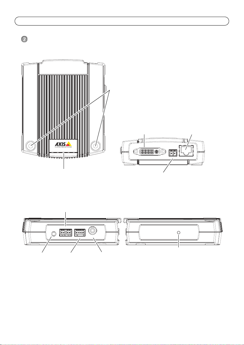
Dimensions
HxWxD = 33 x 99 x 118 mm (1.3 x 3.9 x 4.7 in)
Weight = 318 g (0.7 lb) power supply excluded
LED indicators for
power, status,
network and video
Control button
Video out
RS422/RS485 connector
Audio out
4-pin I/O terminal
Power adapter connector
Top view
Rear view
Audio, Video and I/O side view Control button side view
Mounting holes
DVI-I connector
Network connector (PoE)
Hardware overview
DVIOUT
AXIS P7701 Installation Guide Page 5
1
2
1234
Unit connectors
Network connector - RJ45 Ethernet connector. Supports Power over Ethernet (PoE). Using
shielded cables is recommended.
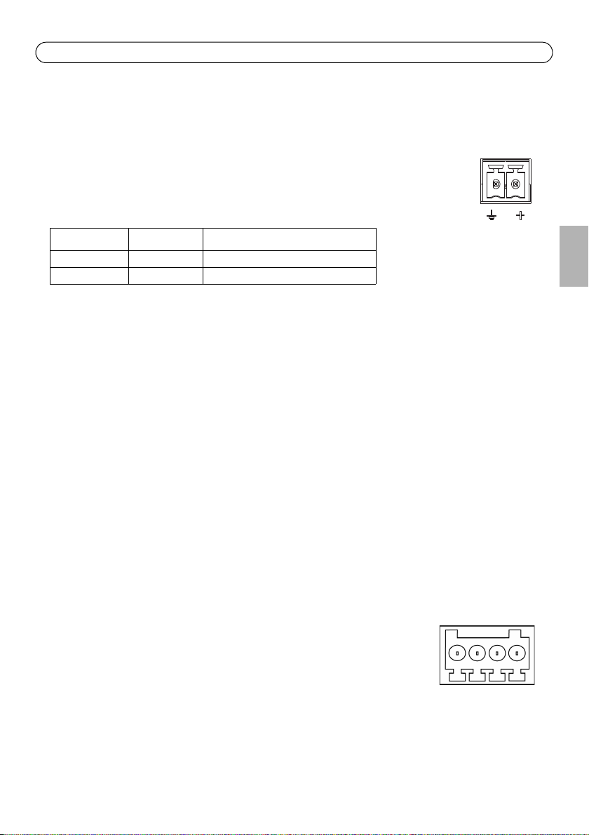
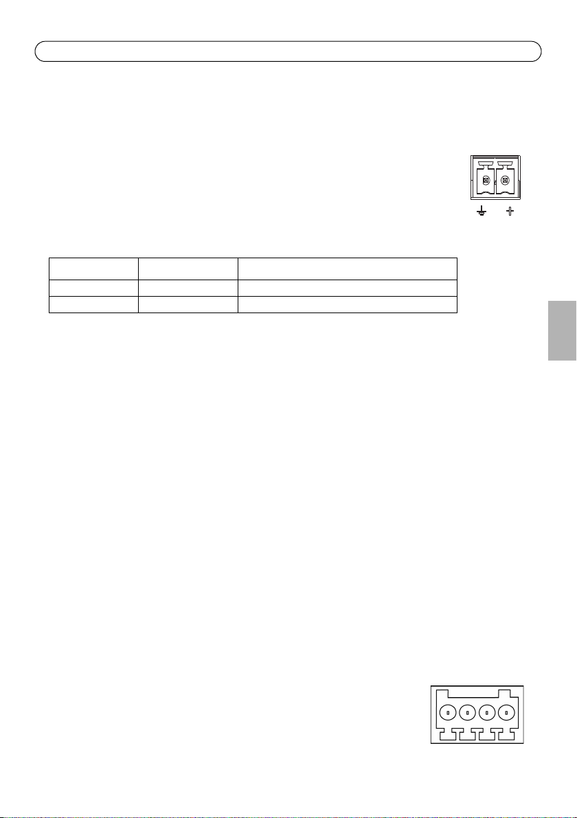
Power connector - 2-pin terminal block used for power input to the video decoder
with the supplied power adapter or an external power supply 8-20V DC, max. 8.3 W.
Function Pin number Description
GND 1 Ground
DC Power 2 Power input 8-20V DC, max 8.3W
Note:
Do not connect a power supply if the video decoder is connected to PoE.
Audio out - Audio output that can be connected to a public address (PA) system or an active
speaker with a built-in amplifier. A pair of headphones can also be attached. A stereo connector
must be used for the audio out.
DVI-I connector - The DVI-I connector has both analog and digital signals present simultaneously,
so the DVI connector can be used to connect to a monitor with either digital or analog input.
For digital input, the DVI-I connector can also be used to connect the AXIS P7701 to a monitor with
a DVI input, or to a monitor with a HDMI connector with the addition of a DVI-to-HDMI adapter.
The DVI connector can also be used with a DVI-to-VGA adapter to connect the AXIS P7701 to a
monitor with a VGA analog input.
RCA connector - Standard phono-type connector for composite video in PAL or NTSC. Allows
direct connection of an analog TV device.
Note:
If you connect the AXIS P7701 to a monitor using the RCA connector, you cannot use the DVI-I connector at the same time to connect to a second monitor.
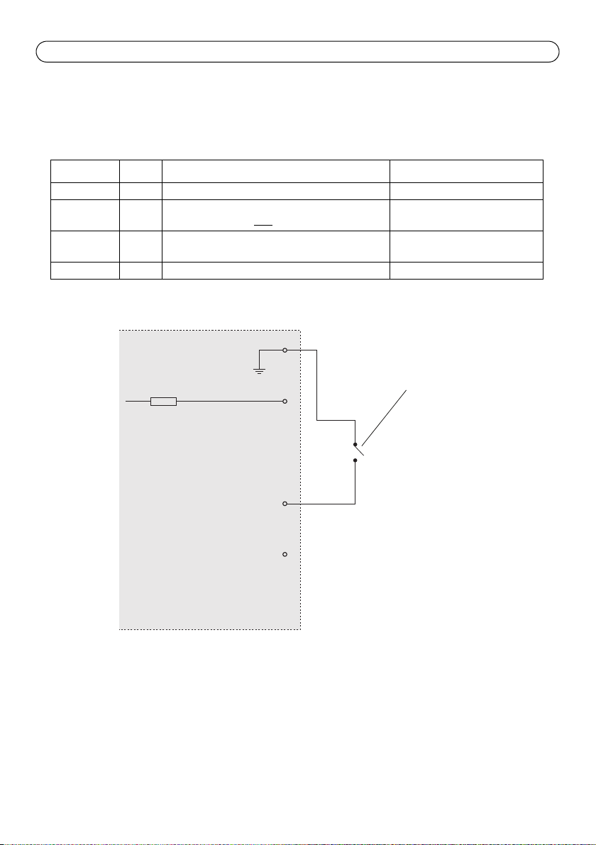
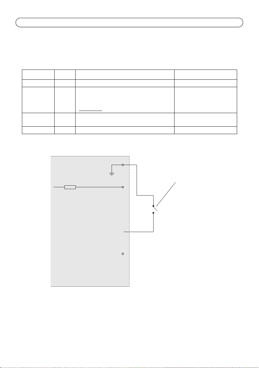
I/O terminal connector - The AXIS P7701 has one digital input that is used
for a video select switch, and it has an interface for auxiliary power and
GND. The fourth I/O pin is unused.
ENGLISH
Page 6 AXIS P7701 Installation Guide
1
2
Push to trigger video select
Switch
3 video input
4 Unused
AXIS P7701
3.3V max 250mA
Note:
A video select switch is not included in the package with the AXIS P7701, and there is currently no
optional video switch available from Axis. However, it is possible for you to easily connect your own
switch. See the connection diagram below.
Function Pin Notes Specifications
GND 1 Ground
3.3V DC
Power
Digital
2 Can be used to power auxiliary equipment.
Note: This pin can only
be used as power out.
3 Input for a video select switch.
Max. load = 250mA
Input
Unused 4 Unused
The following connection diagram gives an example of how to connect an auxiliary device to the
AXIS P7701.
AXIS P7701 Installation Guide Page 7
RS-485/422
RX/TX
1 2 3 4
T X
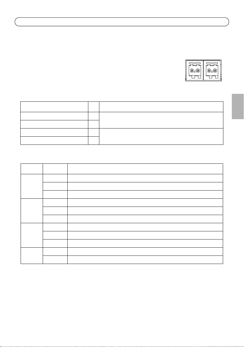
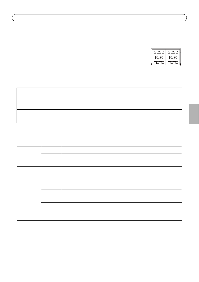
RS422/RS485 connector - Two 2-pin terminal blocks for RS485/422 serial interface used to
control auxiliary equipment, e.g. PTZ devices.
The RS485/422 serial port can be configured to support:
RS-485/422
• Two-wire RS485 half duplex
• Four-wire RS485 full duplex
• Two-wire RS422 simplex
• Four-wire RS422 full duplex point to point communication
Function Pin Notes
RS485/422 RX/TX A 1 (RX) For full duplex RS485/422
RS485/422 RX/TX B 2
RS485/422 TX A 3 (TX) For full duplex RS485/422
RS485/422 TX B 4
(RX/TX) For half duplex RS485
RX/TX
LED indicators
LED Color Indication
Video Green Encoder/Camera is connected.
Amber Steady when connecting to an Encoder/Camera.
Red No Encoder/Camera is connected.
Network Green Steady for connection to a 100 Mbit/s network. Flashes for network activity.
Amber Steady for connection to 10 Mbit/s network. Flashes for network activity.
Unlit No network connection.
Status Green Steady green for normal operation.
Amber Steady during startup, during reset to factory default or when restoring settings.
Red Slow flash for failed upgrade.
Power Green Normal operation.
Amber Flashes green/amber during firmware upgrade.
ENGLISH

Page 8 AXIS P7701 Installation Guide
Install the hardware
IMPORTANT! - The casing of the AXIS P7701 is not approved for outdoor use - the
product may only be installed in indoor environments.
!
Mount the video decoder
The video decoder is supplied with a mounting kit containing screws, plugs, and protective pads for
mounting the video decoder to a concrete wall:
1. Place the video decoder against the wall, and mark the location of the two mounting holes
(See Hardware overview, on page 4) through which the video decoder will be attached.
2. Remove the video decoder and drill the two mounting holes.
3. Punch out the four protective pads and apply them to the underside of the video decoder.
4. Insert the wall plugs into the wall, position the video decoder, and attach it to the wall using
the screws provided.
Connect the cables
1. Connect the decoder to the network using a shielded network cable.
2. Optionally connect external input/output devices, e.g. alarm devices. See Unit connectors, on
page 5 for information on the terminal connector pins.
3. Optionally connect an active speaker and/or external microphone.
4. Connect the decoder to the monitor.
5. Connect power, using one of the methods listed below:
• PoE (Power over Ethernet, Class 2). If available, this is automatically detected when the
network cable is connected (see above).
• Connect the supplied indoor power supply to the power connector on the decoder.
6. Check that the indicator LEDs indicate the correct conditions. See the table in LED indicators, on
page 7 for further details.
AXIS P7701 Installation Guide Page 9
Assign an IP address
Follow these instructions to assign an IP address or see page 13 for other methods of connecting the
AXIS P7701 to the Internet.
Assign an IP address
Most networks today have a DHCP server that automatically assigns IP addresses to connected
devices. If your network does not have a DHCP server the AXIS P7701 will use 192.168.0.90 as the
default IP address.
If you would like to assign a static IP address, the recommended method in Windows is either AXIS
IP Utility or AXIS Camera Management. Depending on the number of decoders you wish to install,
use the method that best suits your purpose.
Both of these free applications are available at www.axis.com/techsup
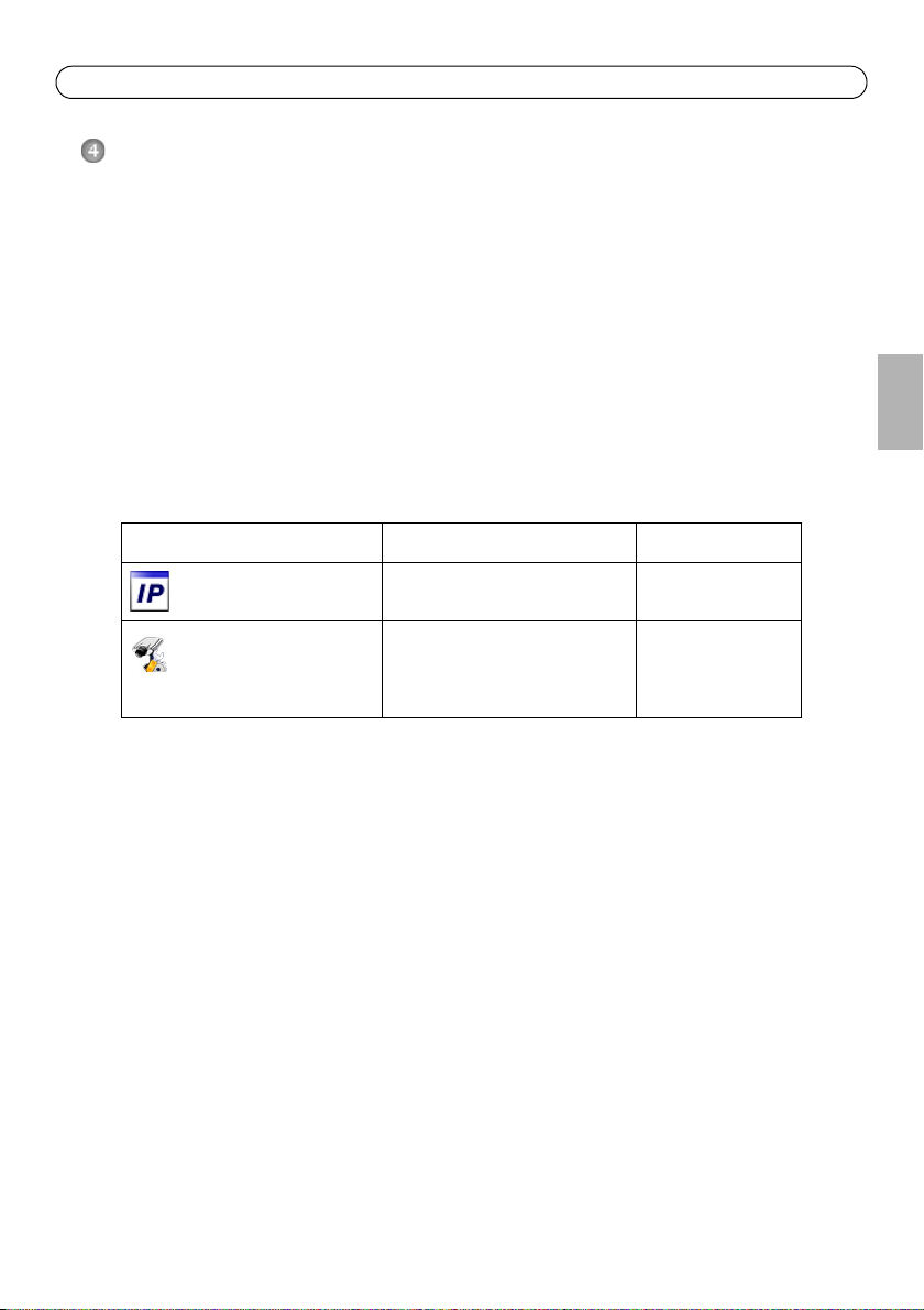
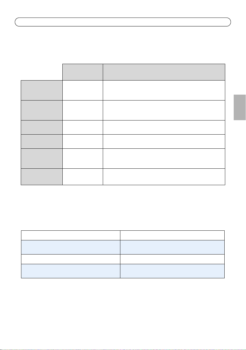
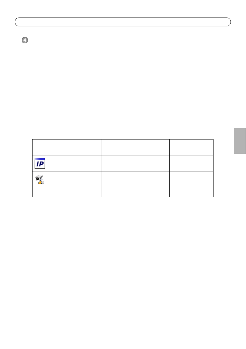
Method Recommended for Operating system
AXIS IP Utility
See page 10
AXIS Camera Management
See page 11
Single camera
Small installations
Multiple cameras
Large installations
Installation on a different subnet
Windows
Windows 2000
Windows XP Pro
Windows 2003 Server
Windows Vista
ENGLISH
Notes:
• If assigning the IP address fails, check that there is no firewall blocking the operation.
• For other methods of assigning or discovering the IP address of the AXIS P7701, e.g. in other operating
systems, see page 13.
Page 10 AXIS P7701 Installation Guide
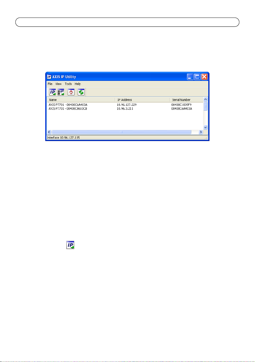
AXIS IP Utility - single decoder/small installation
AXIS IP Utility automatically discovers and displays Axis devices on your network. The application
can also be used to manually assign a static IP address.
Note that the computer running AXIS IP Utility must be on the same network segment (physical
subnet) as the AXIS P7701.
Automatic discovery
1. Check that the AXIS P7701 is connected to the network and that power has been applied.
2. Start AXIS IP Utility.
3. When the decoder appears in the window, double-click it to open its home page.
4. See page 12 for instructions on how to assign the password.
Assign the IP address manually (optional)
1. Acquire an unused IP address on the same network segment as your computer.
2. Select the AXIS P7701 in the list.
3. Click the button Assign new IP address to the selected device and enter the IP address.
4. Click the Assign button and follow the on-screen instructions. Note that the decoder must be
restarted within 2 minutes for the new IP address to be set.
5. Click the Home Page button to access the decoder’s web pages.
6. See page 12 for instructions on how to set the password.
AXIS P7701 Installation Guide Page 11
AXIS Camera Management - multiple decoders/large installations
AXIS Camera Management can automatically discover multiple Axis devices, show connection
status, manage firmware upgrades and set IP addresses.
Automatic discovery
1. Check that the decoder is connected to the network and that power has been applied.
2. Start AXIS Camera Management. When the AXIS P7701 appears in the window, double-click it
to open the decoder’s home page.
3. See page 12 for instructions on how to set the password.
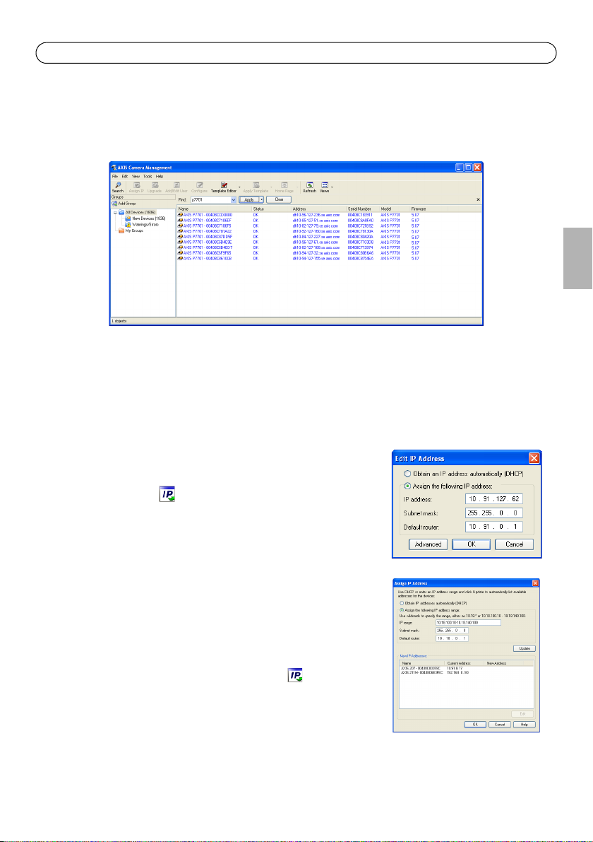
Assign an IP address in a single device
1. Select AXIS P7701 in AXIS Camera Management and click the
Assign IP button.
2. Select Assign the following IP address and enter the IP
address, subnet mask and default router the device will use.
3. Click the OK button.
ENGLISH
Assign IP addresses in multiple devices
AXIS Camera Management speeds up the process of assigning IP
addresses to multiple devices, by suggesting IP addresses from a
specified range.
1. Select the devices you wish to configure (different models can
be selected) and click the Assign IP button.
2. Select Assign the following IP address range and enter the
range of IP addresses, the subnet mask and default router the
devices will use.
3. Click the OK button.
Page 12 AXIS P7701 Installation Guide
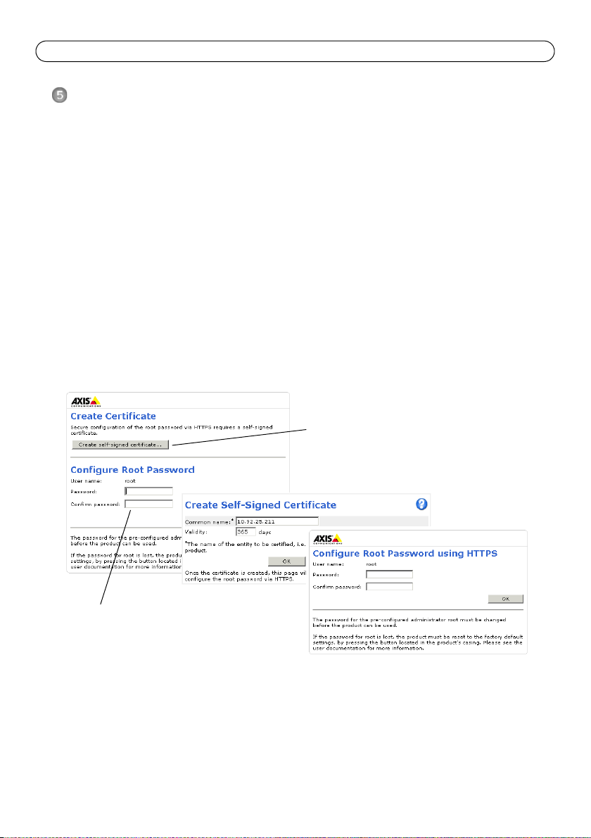
To configure the password directly
via an unencrypted connection, enter
the password here.
To create an HTTPS connection,
start by clicking this button.
Set the password
To gain access to the product, the password for the default administrator user root must be set. This
is done in the ‘Configure Root Password’ dialog, which is displayed when the AXIS P7701 is
accessed for the first time.
To prevent network eavesdropping when setting the root password, this can be done via an
encrypted HTTPS connection, which requires an HTTPS certificate (see note below).
To set the password via a standard HTTP connection, enter it directly in the first dialog shown
below.
To set the password via an encrypted HTTPS connection, follow these steps:
1. Click the Create self-signed certificate button.
2. Provide the requested information and click OK. The certificate is created and the password can
now be set securely. All traffic to and from the AXIS P7701 is encrypted from this point on.
3. Enter a password and then re-enter it to confirm the spelling. Click OK. The password has now
been configured.
4. To log in, enter the user name “root” in the dialog as requested
Note: The default administrator user name root cannot be deleted.
5. Enter the password as set above, and click OK.
AXIS P7701 Installation Guide Page 13
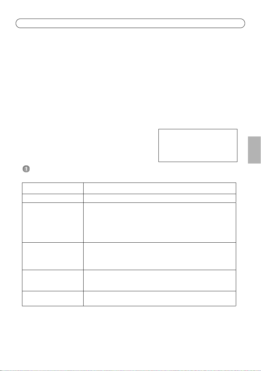
Other methods of setting the IP address
The table below shows the other methods available for setting or discovering the IP address. All
methods are enabled by default, and all can be disabled.
AVHS Service
Connection
AXIS Dynamic DNS
Service
ARP/Ping
UPnP™
Bonjour
View DHCP server
admin pages
Use in operating
system
All To connect the decoder to an AVHS server, refer to the server
All A free service from Axis that allows you to quickly and simply
All See below. The command must be issued within 2 minutes of
Windows
(ME or XP)
MAC OSX
(10.4 or later)
All To view the admin pages for the network DHCP server, see the
Notes
provider’s Installation guide. For information and help to find a
local AVHS Service Provider go to www.axis.com
install your decoder. Requires an Internet connection with no
HTTP proxy. See www.axiscam.net for more information.
connecting power to the decoder.
When enabled on your computer, the decoder is automatically
detected and added to “My Network Places.”
Applicable to browsers with support for Bonjour. Navigate to the
Bonjour bookmark in your browser (e.g. Safari) and click on the
link to access the decoder’s web pages.
server’s own documentation.
Set the IP address with ARP/Ping
1. Acquire an IP address on the same network segment your computer is connected to.
2. Locate the serial number (S/N) on the AXIS P7701 label.
3. Open a command prompt on your computer and enter the following commands:
Windows syntax: Windows example:
arp -s <IP Address> <Serial Number>
ping -l 408 -t <IP Address>
UNIX/Linux/Mac syntax: UNIX/Linux/Mac example:
arp -s <IP Address> <Serial Number> temp
ping -s 408 <IP Address>
arp -s 192.168.0.125 00-40-8c-18-10-00
ping -l 408 -t 192.168.0.125
arp -s 192.168.0.125 00:40:8c:18:10:00 temp
ping -s 408 192.168.0.125
ENGLISH
4. Check that the network cable is connected to the decoder and then start/restart the decoder, by
disconnecting and reconnecting power.
5. Close the command prompt when you see ‘Reply from 192.168.0.125: ...’ or similar.
6. In your browser, type in http://<IP address> in the Location/Address field and press Enter on
your keyboard.
Notes:
• To open a command prompt in Windows: from the Start menu, select Run... and type cmd. Click OK.
• To use the ARP command on a Mac OS X, use the Terminal utility in Application > Utilities.

Page 14 AXIS P7701 Installation Guide
Tip!
Visit www.axis.com/techsup to check if there is updated firmware available for your AXIS
P7701. To see the currently installed firmware version, see About.
Resetting to the Factory Default Settings
This will reset all parameters, including the IP address, to the Factory Default settings:
1. Disconnect power from the decoder.
2. Press and hold the Control button and reconnect power.
3. Keep the Control button pressed until the Power indicator displays amber (this may take up to
15 seconds).
4. Release the Control button. When the Power indicator displays green (which can take up to 1
minute) the process is complete and the decoder has been reset.
5. Re-assign the IP address, using one of the methods described in this document.
It is also possible to reset parameters to the original factory default settings via the web interface.
For more information, please see the online help or the user’s manual.
Accessing the decoder from the Internet
Once installed, your AXIS P7701 is accessible on your local network (LAN). To access the decoder
from the Internet, network routers must be configured to allow incoming traffic, which is usually
done on a specific port
• HTTP port (default port 80) for configuration
Please refer to the documentation for your router for further instructions. For more information on
this and other topics, visit the Axis Support Web at www.axis.com/techsup
Further information
The user’s manual is available from the Axis Web site at www.axis.com
Guide d’installation de l’AXIS P7701 Page 15
Important !
Ce produit doit être utilisé
conformément aux lois et
dispositions locales en vigueur.
AXIS P7701 Guide d’installation
Ce guide d’installation explique comment installer le Décodeur vidéo AXIS P7701 sur votre réseau.
Pour toute autre information relative à l’utilisation du produit, consultez le manuel de l’utilisateur
disponible sur le site www.axis.com/techsup
Procédure d’installation
1. Vérification du contenu de l’emballage par rapport à la liste ci-dessous.
2. Vue d’ensemble du matériel. Reportez-vous à la page 16.
3. Installation du matériel. Reportez-vous à la page 20.
4. Attribution d’une adresse IP. Reportez-vous à la page
21.
5. Configuration du mot de passe. Reportez-vous à la page
25.
Contenu de l’emballage
Article Modèles/variantes/remarques
Décodeur vidéo AXIS P7701 - Décodeur vidéo
Alimentation d’intérieur PS-T
ou PS-K
(selon le pays)
Bloc de connexion pour
terminaux
Kit de montage Deux vis inviolables
Documentation imprimée Guide d’installation de l’AXIS P7701 (le présent document)
Europe
Royaume-Uni
Australie
États-Unis/Japon
Argentine
Corée
Bloc de connexion à 4 broches pour le raccordement d’équipements externes
au connecteur pour terminaux
Alimentation en courant continu du connecteur pour terminaux
Connecteurs pour terminaux RS422/485
Un jeu de 4 patins en caoutchouc
Deux chevilles
Document de garantie d’Axis
FRAN
Ç
AIS

Page 16 AXIS P7701 Guide d’installation
DVI
OUT
POW E R
PoE
-
+
P
WR
STA
T NET
VID
E
O
AUDIOOUTAUDIOOUT
RS-485/422RS-485/422
RX/TXRX/TX
I/O
TX
12341234
VIDEO OUT
VIDEO
OUT
Dimensions
H x L x P = 33 x 99 x 118 mm
Poids = 318 g (alimentation exclue)
Voyants pour
l’alimentation, l’état,
le réseau et la vidéo
Bouton de
commande
Sortie
vidéo
Connecteur RS422/RS485
Sortie
audio
Terminal d’E/S à 4
broches
Connecteur d’adaptateur secteur
Vue de dessus
Vue de derrière
Vue de côté E/S, audio et vidéo Vue de côté bouton de commande
Trous de fixation
Connecteur DVI-I
Connecteur réseau (PoE)
Description du matériel
DVIOUT
Guide d’installation de l’AXIS P7701 Page 17
1
2
1234
Connecteurs de l’appareil
Connecteur réseau - Connecteur Ethernet RJ45. Prend en charge l’alimentation par Ethernet (PoE).
Il est recommandé d’utiliser des câbles blindés.
Connecteur d’alimentation - Bloc terminal à 2 broches utilisé pour alimenter le
décodeur vidéo avec l’adaptateur secteur fourni ou un bloc d’alimentation externe 820 V CC, max. 8,3 W.
Fonction Numéro de broche Description
Terre 1 Terre
Alimentation CC 2 Puissance d’entrée 8-20 V CC, max. 8,3 W
FRAN
Remarque :
Ne branchez pas l’alimentation électrique si le décodeur vidéo est branché sur PoE.
Sortie audio - Sortie audio pouvant être connectée à un système de diffusion publique ou à un
haut-parleur actif avec amplificateur intégré. Il est également possible de connecter une paire
d’écouteurs. Un connecteur stéréo doit être utilisé pour la sortie audio.
Connecteur DVI-I - Le connecteur DVI-I prend en charge les signaux analogiques et numériques. Le
connecteur DVI peut ainsi être utilisé pour brancher un écran à une entrée analogique ou
numérique.
Pour une entrée numérique, le connecteur DVI-I peut aussi être utilisé pour brancher l’AXIS P7701 à
un écran équipé d’un connecteur HDMI au moyen d’un adaptateur DVI-HDMI.
Le connecteur DVI peut être utilisé avec un adaptateur DVI-VGA pour brancher l’AXIS P7701 à un
écran avec entrée VGA analogique.
Connecteur RCA - Connecteur standard de type phono pour des vidéos composites PAL ou NTSC.
Permet la connexion directe à un périphérique TV analogique.
Remarque :
Si vous branchez l’AXIS P7701 à un écran au moyen d’un connecteur RCA, il est impossible de se servir
du connecteur DVI-I en même temps pour brancher un deuxième écran.
Connecteur pour terminaux E/S - L’AXIS P7701 possède une entrée
numérique pour un bouton de sélection vidéo. Il est doté d’une interface
pour l’alimentation auxiliaire et la terre. La quatrième broche E/S est
inutilisée.
Ç
AIS
Page 18 AXIS P7701 Guide d’installation
1
2
la sélection de la vidéo
Interrupteur pour déclencher
3 entrée-vidéo
4 inutilisé
AXIS P7701
3.3V max 250mA
Remarque :
L´interrupteur video n´est pas fourni avec l´Axis P7701, et il n´y a actuellement pas d´interrupteur
vidéo optionnel disponible chez Axis. Cependant, il vous est possible facilement de connecter votre
propore interrupteur en suivant le schéma de connection ci-dessous.
Fonction Broche Remarques Caractéristiques techniques
Terre 1 Terre
Alimentation
en courant
continu de
3,3 V
Entrée
2 Cette broche peut également servir à
l’alimentation du matériel auxiliaire.
Remarque : la broche peut être utilisée
uniquement
comme sortie d’alimentation.
3 Entrée pour bouton de sélection de vidéo.
Charge maximale = 250 mA
numérique
Inutilisée 4 Inutilisée
Le schéma de câblage suivant est un exemple de connexion d’un périphérique auxiliaire à l’AXIS
P7701.
Guide d’installation de l’AXIS P7701 Page 19
RS-485/422
RX/TX
1 2 3 4
T X
Connecteur RS422/RS485 - Deux blocs terminaux à 2 broches pour l’interface série RS485/422
utilisée pour le contrôle des équipements auxiliaires (appareils PTZ, etc.).
Le port série RS485/422 peut être configuré pour la prise en charge de :
RS-485/422
• RS485 semi-duplex sur deux fils
• RS485 semi-duplex sur quatre fils
• RS422 simplex sur deux fils
• RS422 duplex intégral sur quatre fils pour communication point à
RX/TX
point
Fonction Broche Remarques
RS485/422 RX/TX A 1 (RX) Pour RS485/422 duplex intégral
RS485/422 RX/TX B 2
RS485/422 TX A 3 (TX) Pour RS485/422 duplex intégral
RS485/422 TX B 4
(RX/TX) Pour RS485 semi-duplex
Témoins lumineux
DEL Couleur Indication
Vidéo Vert Encodeur/Caméra connecté.
Orange Continu lors de la connexion à un Encodeur/Caméra.
Rouge Aucun Encodeur/Caméra n’est connecté.
Net (Réseau) Vert Continu en cas de connexion à un réseau de 100 Mbits/s. Clignote en cas
d’activité réseau.
Orange Continu en cas de connexion à un réseau de 10 Mbits/s. Clignote en cas
d’activité réseau.
Éteint Pas de connexion au réseau.
Status (État) Vert Vert continu en cas de fonctionnement normal.
Orange En continu pendant le démarrage, la réinitialisation des paramètres d’usine par
défaut ou la restauration des paramètres.
Rouge Clignote lentement en cas d’échec de la mise à niveau.
PWR
(Alimentation)
Vert Fonctionnement normal.
Orange Clignote en vert/orange pendant la mise à niveau du microprogramme.
FRAN
Ç
AIS

Page 20 AXIS P7701 Guide d’installation
Installation du matériel
IMPORTANT ! Le boîtier de l’AXIS P7701 n’est pas approuvé pour une utilisation à
l’extérieur. Le produit doit être installé en intérieur uniquement.
!
Montage du décodeur vidéo
Le décodeur vidéo est fourni avec un kit de montage contenant des vis, des chevilles et des patins
de protection pour la fixation du décodeur vidéo sur un mur en béton :
1. placez le décodeur vidéo contre le mur et marquez l’emplacement des deux trous
(Reportez-vous à la section Description du matériel, page 16) où le décodeur vidéo sera fixé.
2. retirez le décodeur vidéo et percez les deux trous.
3. sortez les quatre patins de protection de leur emballage et posez sur le dessous du décodeur
vidéo.
4. insérez les chevilles dans le mur, positionnez le décodeur vidéo et fixez-le au mur à l’aide
des vis fournies.
Branchement des câbles
1. Connectez le décodeur au réseau à l’aide d’un câble réseau blindé.
2. Si vous le souhaitez, connectez des dispositifs d’entrée/sortie externes, tels que des systèmes
d’alarme. Reportez-vous à la section Connecteurs de l’appareil, page 17 pour plus
d’informations sur les broches du connecteur pour terminaux.
3. Si vous le souhaitez, vous pouvez brancher un haut-parleur actif et/ou un microphone externe.
4. Connectez le décodeur à l’écran.
5. Branchez l’alimentation en suivant une des méthodes décrites ci-dessous :
• PoE (alimentation par Ethernet, classe 2). le PoE, si il est disponible, est
• automatiquement détecté lorsque le câble réseau est connecté (voir ci-dessus).
• branchez le bloc d’alimentation d’intérieur fourni sur le connecteur d’alimentation du
décodeur.
6. vérifiez que les voyants lumineux indiquent les conditions correctes. Pour plus d’informations,
reportez-vous au tableau de la section Témoins lumineux, page 19.
Guide d’installation de l’AXIS P7701 Page 21
Attribution d’une adresse IP
Procédez comme suit pour définir une adresse IP ou Reportez-vous à la page 26 pour d’autres
méthodes de connexion du
Attribution d’une adresse IP
Aujourd’hui, la plupart des réseaux sont équipés d’un serveur DHCP qui attribue automatiquement
des adresses IP aux périphériques connectés. Si votre réseau en est dépourvu, votre AXIS P7701
utilisera 192.168.0.90 comme adresse IP par défaut.
Si vous souhaitez paramétrer une adresse IP statique sous Windows, nous recommandons
l’utilisation de l’application AXIS IP Utility ou de l’application AXIS Camera Management. Selon le
nombre de décodeurs à installer, utilisez la méthode qui vous convient le mieux.
Ces deux applications sont gratuites et peuvent être téléchargées depuis www.axis.com/techsup
Méthode Recommandée pour Système
AXIS IP Utility
Reportez-vous à la page 22
AXIS Camera Management
Reportez-vous à la page
23
AXIS P7701 à Internet.
Une seule caméra
Petites installations
Plusieurs caméras
Grandes installations
Installation sur un autre sousréseau
d’exploitation
Windows
Windows 2000
Windows XP Pro
Windows 2003 Server
Windows Vista
FRAN
Ç
AIS
Remarques :
• En cas d’échec de l’attribution d’adresse IP, vérifiez qu’aucun pare-feu ne bloque l’opération.
• Pour connaître les autres méthodes d’affectation ou de détection de l’adresse IP de votre AXIS P7701, par
exemple sous d’autres systèmes d’exploitation, reportez-vous à la page 26.

Page 22 AXIS P7701 Guide d’installation
AXIS IP Utility - Un seul décodeur/petite installation
AXIS IP Utility détecte automatiquement les périphériques Axis de votre réseau et les affiche. Cette
application sert également à attribuer manuellement une adresse IP statique.
Notez que l’ordinateur exécutant l’application AXIS IP Utility doit se trouver sur le même segment
de réseau (sous-réseau physique) que l’AXIS P7701.
Recherche automatique
1. Vérifiez que l’AXIS P7701 est connecté au réseau et qu’il est sous tension.
2. Lancez AXIS IP Utility.
3. Double-cliquez sur l’icône du décodeur, lorsque celle-ci apparaît dans la fenêtre, pour ouvrir la
page d’accueil correspondante.
4. Reportez-vous à la page 25 pour savoir comment configurer le mot de passe.
Attribution manuelle de l’adresse IP (facultatif)
1. Trouvez une adresse IP inutilisée sur le même segment de réseau que celui de votre ordinateur.
2. SélectionnezAXIS P7701 dans la liste.
3. Cliquez sur le bouton Assign new IP address to the selected device (Attribuer une
nouvelle adresse IP au périphérique sélectionné) et saisissez l’adresse IP.
4. Cliquez sur le bouton Assign (Attribuer) et suivez les instructions affichées à l’écran. Le
décodeur doit être redémarré dans les 2 minutes pour que la nouvelle adresse IP soit prise en
compte.
5. Cliquez sur le bouton Home Page (Page d’accueil) pour accéder aux pages Web du décodeur.
6. Reportez-vous à la page 25 pour la configuration du mot de passe.

Guide d’installation de l’AXIS P7701 Page 23
AXIS Camera Management : plusieurs décodeurs et de grandes
installations
AXIS Camera Management peut détecter automatiquement plusieurs périphériques Axis, afficher
l’état de connexion, gérer les mises à niveau du microprogramme et configurer les adresses IP.
Recherche automatique
1. Vérifiez que le décodeur est connecté au réseau et qu’il est sous tension.
2. Lancez AXIS Camera Management. Double-cliquez sur l’icône de l’AXIS P7701 lorsqu’elle
apparaît dans la fenêtre pour ouvrir la page d’accueil du décodeur.
3. Reportez-vous à la page 25 pour la configuration du mot de passe.
FRAN
Ç
AIS
Attribution d’une adresse IP à un seul périphérique
1. SélectionnezAXIS P7701 dans l’application AXIS Camera
Management, puis cliquez sur le bouton Assign IP (Attribuer
une adresse IP).
2. Sélectionnez Assign the following IP address (Attribuer
l’adresse IP suivante) et saisissez l’adresse IP, le masque de
sous-réseau et le routeur par défaut que le périphérique
utilisera.
3. Cliquez sur le bouton OK.
Attribution d’adresses IP à plusieurs périphériques
AXIS Camera Management accélère le processus d’attribution
d’adresses IP à plusieurs périphériques en suggérant des adresses IP
parmi une plage spécifiée.
1. Sélectionnez les périphériques à configurer (il peut s’agir de
plusieurs modèles), puis cliquez sur le bouton Assign IP
(Attribuer une adresse IP).

Page 24 AXIS P7701 Guide d’installation
2. Sélectionnez Assign the following IP address range (Attribuer la plage d’adresses IP suivante)
et saisissez la plage d’adresses IP, le masque de sous-réseau et le routeur par défaut que les
périphériques utiliseront.
3. Cliquez sur le bouton OK.

Guide d’installation de l’AXIS P7701 Page 25
Pour configurer directement le mot
de passe via une connexion cryptée,
saisissez le mot de passe à cet
endroit.
Pour créer une connexion HTTPS,
cliquez sur ce bouton.
Configuration du mot de passe
Pour accéder au produit, le mot de passe par défaut de l’administrateur, root, doit être configuré.
Vous pouvez effectuer cette opération dans la boîte de dialogue Configure Root Password
(Configurer le mot de passe root) qui s’affiche lors du premier accès à l’AXIS P7701.
Pour éviter les écoutes électroniques lors de la configuration du mot de passe root, utilisez une
connexion HTTPS cryptée nécessitant un certificat HTTPS (voir la remarque ci-dessous).
Pour configurer le mot passe avec une connexion HTTP standard, saisissez directement le mot de
passe dans la première boîte de dialogue représentée ci-dessous.
Pour configurer le mot passe avec une connexion HTTPS cryptée, procédez comme suit :
1. cliquez sur le bouton Create self-signed certificate (Créer un certificat autosigné).
2. saisissez les informations demandées, puis cliquez sur OK. le certificat est créé et le mot de
passe peut maintenant être configuré en toute sécurité. tout le trafic vers et depuis l’AXIS
P7701 est désormais crypté.
3. saisissez un mot de passe, puis saisissez-le de nouveau pour confirmation. cliquez sur OK. le
mot de passe est maintenant configuré.
FRAN
Ç
AIS
4. Pour vous connecter, saisissez le nom d’utilisateur « root » dans la boîte de dialogue à l’invite.
Remarque : le nom d’utilisateur par défaut de l’administrateur est root et il ne peut pas être
supprimé.
5. Saisissez le mot de passe configuré ci-dessus et cliquez sur OK.

Page 26 AXIS P7701 Guide d’installation
Autres méthodes de définition de l’adresse IP
Le tableau ci-dessous indique les autres méthodes permettant de configurer ou de déterminer
l’adresse IP. Toutes les méthodes sont activées par défaut et peuvent être désactivées.
AVHS Service
Connection
AXIS Dynamic DNS
Service
ARP/Ping
UPnP™
Bonjour
Affichage des pages
administratives du
serveur DHCP
Utilisation sous un
système
d’exploitation
Tous Pour connecter le décodeur à un serveur AVHS, reportez-vous au
Tous Service gratuit offert par Axis pour vous permettre d’installer
Tous Reportez-vous aux instructions ci-dessous. La commande doit
Windows
(ME ou XP)
MAC OS X
(10.4 ou version
ultérieure)
Tous Pour consulter les pages administratives du serveur DHCP réseau,
Remarques
Guide d’installation du fournisseur. Pour obtenir des
renseignements et trouver un fournisseur de service VHS,
consultez le site www.axis.com
rapidement et facilement votre décodeur. Nécessite une
connexion Internet sans proxy HTTP. Pour plus d’informations,
consultez le site www.axiscam.net.
être saisie dans les 2 minutes suivant la mise sous tension du
décodeur.
Lorsque le décodeur est activé sur votre ordinateur, il est détecté
et ajouté automatiquement au dossier Favoris réseau.
Pour les navigateurs compatibles avec Bonjour : accédez au
signet Bonjour dans votre navigateur (par exemple, Safari), puis
cliquez sur le lien pour accéder aux pages Web du décodeur.
reportez-vous à la documentation du serveur.
Définition de l’adresse IP à l’aide d’ARP/Ping
1. Trouvez une adresse IP sur le même segment de réseau que celui de votre ordinateur.
2. Repérez le numéro de série (S/N) sur l’étiquette de l’AXIS P7701.
3. Ouvrez une invite de commande sur votre ordinateur et saisissez les commandes suivantes :
Syntaxe pour Windows : Exemple pour Windows :
arp -s <Adresse IP> <Numéro de série>
ping -l 408 -t <Adresse IP>
Syntaxe pour UNIX/Linux/Mac : Exemple pour UNIX/Linux/Mac :
arp -s <Adresse IP> <Numéro de série> temp
ping -s 408 <Adresse IP>
arp -s 192.168.0.125 00-40-8c-18-10-00
ping -l 408 -t 192.168.0.125
arp -s 192.168.0.125 00:40:8c:18:10:00 temp
ping -s 408 192.168.0.125
4. Vérifiez que le câble réseau est connecté au décodeur, puis démarrez/redémarrez ce dernier en
débranchant, puis en rebranchant l’alimentation.
5. Fermez l’invite de commande lorsque le message « Reply from 192.168.0.125:... » (Réponse de
192.168.0.125 : ...) ...’ ou un message similaire s’affiche.

Guide d’installation de l’AXIS P7701 Page 27
6. Dans votre navigateur, tapez http://<Adresse IP> dans le champ Emplacement/Adresse, puis
appuyez sur la touche Entrée de votre clavier.
Remarques :
• Ouvrir une invite de commande sous Windows : dans le menu Démarrer, sélectionnez Exécuter… et tapez
cmd. Cliquez sur OK.
• Pour utiliser la commande ARP sous Mac OS X, utilisez l’utilitaire Terminal dans Application> Utilitaires.
FRAN
Ç
AIS

Page 28 AXIS P7701 Guide d’installation
Conseil :
visitez le site www.axis.com/techsup pour vérifier si des mises à jour de microprogrammes
sont disponibles pour votre AXIS P7701. Pour connaître la version du microprogramme
actuellement installée, reportez-vous à la page About (Configuration - À propos de).
Rétablissement des paramètres d’usine par défaut
Procédez comme suit pour rétablir tous les paramètres par défaut définis en usine, y compris
l’adresse IP :
1. débranchez l’alimentation du décodeur.
2. maintenez le bouton de commande enfoncé et rebranchez l’alimentation.
3. Appuyez sur le bouton jusqu’à ce que le voyant d’alimentation passe à l’orange et clignote (cela
peut prendre jusqu’à 15 secondes).
4. relâchez le bouton de commande. Quand le voyant d’alimentation émet une lumière verte (ce
qui peut prendre 1 minute), le décodeur est revenu aux réglages par défaut définis en usine.
5. Attribuez à nouveau l’adresse IP à l’aide de l’une des méthodes décrites dans ce document.
Il est également possible de rétablir les paramètres d’usine par défaut d’origine à partir de
l’interface web. Pour plus d’informations, reportez-vous à l’aide en ligne ou au manuel d’utilisation.
Accès au décodeur sur Internet
Une fois installée, votre AXIS P7701 est accessible sur votre réseau local (LAN). Pour accéder au
décodeur via Internet, des routeurs réseau doivent être configurés pour autoriser le trafic entrant,
ce qui est généralement réalisé sur un port spécifique.
• Port HTTP (port 80 par défaut) pour la configuration
Pour plus d’informations, consultez la documentation du routeur. Pour plus d’informations à ce
sujet ou pour toute autre question, consultez la page Axis Support Web à l’adresse www.axis.com/
techsup.
Plus d’informations
Le manuel de l’utilisateur est disponible sur le site Web d’Axis (www.axis.com).

AXIS P7701 Installationsanleitung Seite 29
Wichtig!
Verwenden Sie dieses Produkt
unter Beachtung der geltenden
rechtlichen Bestimmungen.
AXIS P7701 Installationsanleitung
In dieser Anleitung wird die Installation der AXIS P7701 Video-Decoder in einem Netzwerk
beschrieben. In dieser Anleitung wird die Installation der AXIS P7701 Video-Decoder in einem
Netzwerk beschrieben. Weitere Informationen zur Nutzung dieses Produkts finden Sie im
Benutzerhandbuch unter www.axis.com/techsup
Installationsschritte
1. Prüfen Sie, ob alle in der nachfolgenden Liste aufgeführten Komponenten vorhanden sind.
2. Sehen Sie sich die Hardwareübersicht an. Siehe Seite 30.
3. Installieren Sie die Hardware. Siehe Seite 34.
4. Weisen Sie eine IP-Adresse zu. Siehe Seite 35.
5. Legen Sie das Kennwort fest. Siehe Seite 39.
Lieferumfang
Komponente Modell/Varianten/Anmerkungen
Video-Decoder AXIS P7701 - Video-Decoder
PS-T oder PS-K Netzteil für
geschlossene Räume
(landesspezifisch)
Klemmenblock-Anschluss 4-polige E/A-Anschlussleiste
Montagesatz Zwei manipulationssichere Schrauben
Gedruckte Dokumente AXIS P7701 Installationsanleitung (dieses Dokument)
Europa
Großbritannien
Australien
USA/Japan
Argentinien
Korea
Gleichstromeingang
RS422/485-Anschlüsse
Sortiment von 4 Gummifüßen
Zwei Wanddübel
Axis-Garantieerklärung
DEUTSCH

Seite 30 AXIS P7701 Installationsanleitung
DVI
OUT
POW E R
PoE
-
+
P
WR
STA
T NET
VID
E
O
AUDIOOUTAUDIOOUT
RS-485/422RS-485/422
RX/TXRX/TX
I/O
TX
12341234
VIDEO OUT
VIDEO
OUT
Abmessungen
H x B x T = 33 x 99 x 118mm
Gewicht = 318 g (ohne Netzteil)
LED-Anzeigen für
Strom, Status,
Netzwerk und Video
Steuertaste
VideoAusgang
RS422/RS485-Anschluss
Audioaus
gang
4-polige E/AAnschlussklemme
Netzteilanschluss
Draufsicht
Rückansicht
Audio, Video und E/A (Seitenansicht) Steuertaste (Seitenansicht)
Montagebohrungen
DVI-I-Anschluss
Netzwerkanschluss (mit PoE)
Hardwareübersicht
DVIOUT

AXIS P7701 Installationsanleitung Seite 31
1
2
1234
Geräteanschlüsse
Netzwerkanschluss - RJ45-Ethernetanschluss. Unterstützt PoE-Anschluss (Power over Ethernet).
Die Verwendung von abgeschirmten Kabeln wird empfohlen.
Netzanschluss - 2-poliger Anschlussblock für Netzeingang. Zur Stromversorgung
des Video-Decoders über das mitgelieferte Netzteil oder ein externes Netzteil mit 8–
20 V Gleichstrom und max. 8,3 W.
Funktion Anschlussnummer Beschreibung
Schutzleiter 1 Masse
Gleichstrom 2 Netzeingang 8–20 V Gleichstrom, max. 8,3 W
Hinweis:
Schließen Sie kein Netzteil an, wenn der Video-Decoder über PoE angeschlossen ist.
Audioausgang - Audioausgang zum Anschließen einer Rundrufanlage (PA) oder eines
Aktivlautsprechers mit integriertem Verstärker. Auch ein Kopfhörer kann angeschlossen werden. Für
den Audioausgang muss ein Stereostecker benutzt werden.
DVI-I-Anschluss - Über den DVI-I-Anschluss ist die Übertragung analoger und digitaler Daten
möglich, so dass Sie Bildschirme mit digitalen und Analogeingängen anschließen können.
Als digitalen Eingang können Sie den AXIS P7701 über den DVI-I-Anschluss und einem geeigneten
DVI-zu-HDMI-Adapter auch an Bildschirme mit HDMI-Anschluss anschließen.
Mit Hilfe eines DVI-zu-VGA-Adapters ist außerdem der Anschluss des AXIS P7701 an Bildschirme
mit analogen VGA-Eingängen möglich.
RCA-Anschluss - Gebräuchlicher Cinch-Stecker für Composite Video in PAL oder NTSC. Ermöglicht
den direkten Anschluss von analogen TV-Geräten.
Hinweis:
Wenn Sie den AXIS P7701über den RCA-Anschluss an einen Bildschirm anschließen, ist es nicht
möglich, einen zweiten Bildschirm über den DVI-I-Anschluss anzuschließen.
E/A-Anschluss - Der AXIS P7701 verfügt über einen digitalen Eingang für
eine Videoauswahltaste und eine Schnittstelle für Zusatzstromversorgung
und Masse. Der vierte E/A-Kontakt ist nicht belegt.
Hinweis:
Der Video-Schalter ist im AXIS P7701 nicht integriert,und derzeit bietet Axis
dieses Zubehör leider nicht an. Es ist jedoch möglich, dass Sie Ihren eigenen
Schalter anschliessen. Siehe Anschlussbild unten.
DEUTSCH

Seite 32 AXIS P7701 Installationsanleitung
1
2
Push to trigger video select
Switch
3 video input
4 Unused
AXIS P7701
3.3V max 250mA
z.B. Schalter
Funktion Kontakt Hinweise Spezifikationen
Schutzleiter 1 Masse
3,3 V
Gleichstrom
2 Dieser Kontakt kann auch für die
Stromversorgung von Zusatzgeräten
Max. Stromstärke = 250 mA
verwendet werden.
Hinweis: Dieser Anschluss kann nur
als
Stromausgang verwendet werden.
Digitaler
3 Eingang für Videoauswahltaste.
Eingang
Nicht belegt 4 Nicht belegt
Das folgende Anschlussschaltbild zeigt ein Beispiel für den Anschluss eines Zusatzgeräts an den
AXIS P7701.

AXIS P7701 Installationsanleitung Seite 33
RS-485/422
RX/TX
1 2 3 4
T X
RS422/RS485-Anschluss - Zwei 2-polige Anschlussblöcke für serielle Schnittstellen vom Typ
RS485/422 zur Steuerung von Zusatzgeräten, wie z. B. PTZ-Geräten.
Der serielle RS485/422-Anschluss kann in den folgenden Anschlussmodi
RS-485/422
konfiguriert werden:
• zwei-Draht RS485-Halbduplex-Anschluss
• vier-Draht RS485-Vollduplex-Anschluss
• zwei-Draht RS422 Simplex-Anschluss
RX/TX
• vier-Draht RS422-Vollduplex-Anschluss (Punkt-zu-PunktVerbindung)
Funktion Kontakt Hinweise
RS485/422 RX/TX A 1 (RX) Für Vollduplex RS485/422
RS485/422 RX/TX B 2
RS485/422 TX A 3 (TX) Für Vollduplex RS485/422
RS485/422 TX B 4
(RX/TX) Für Halbduplex RS485
LED-Anzeigen
LED Farbe Bedeutung
Video Grün Encoder/Kamera ist angeschlossen.
Gelb Leuchtet dauerhaft bei Verbindung mit einem Encoder bzw. einer Kamera.
Rot Encoder/Kamera ist nicht angeschlossen.
Netzwerk Grün Leuchtet dauerhaft bei Verbindung mit einem 100-MBit/s-Netzwerk. Blinkt bei
Gelb Leuchtet dauerhaft bei Verbindung mit einem 10-MBit/s-Netzwerk. Blinkt bei
Leuchtet
nicht
Status Grün Leuchtet bei Normalbetrieb konstant grün.
Gelb Leuchtet dauerhaft beim Start und beim Wiederherstellen der Werkseinstellungen
Rot Blinkt langsam bei Aktualisierungsfehler.
Betrieb Grün Normaler Betrieb.
Gelb Blinkt grün/gelb während Firmware-Aktualisierung.
Netzwerkaktivität.
Netzwerkaktivität.
Keine Netzwerkverbindung vorhanden.
bzw. von vorherigen Einstellungen.
DEUTSCH

Seite 34 AXIS P7701 Installationsanleitung
Installation der Hardware
WICHTIG! - Das Gehäuse des AXIS P7701 ist nicht für den Einsatz im Außenbereich
geeignet; das Gerät darf nur in Innenräumen installiert werden.
!
Montage des Video-Decoders
Der Video-Decoder wird mit einem Montagesatz mit Schrauben, Dübeln und Schutzfüßen geliefert,
um den Video-Decoder an einer Betonwand zu befestigen:
1. Halten Sie den Video-Decoder an die Wand und markieren Sie die Stelle der beiden
Montagebohrungen
(siehe Hardwareübersicht, auf Seite 30), über die der Video-Decoder befestigt wird.
2. Nehmen Sie den Video-Decoder ab und bohren Sie die Montagelöcher in die Wand.
3. Drücken Sie die vier Schutzfüße heraus und kleben Sie sie auf die Unterseite des VideoDecoders.
4. Drücken Sie die Wanddübel in die Löcher, positionieren Sie den Video-Decoder an der Wand
und befestigen Sie ihn mit den
mitgelieferten Schrauben.
Anschließen der Kabel
1. Verbinden Sie den Decoder über ein abgeschirmtes Netzwerkkabel mit dem Netzwerk.
2. Sie können zusätzlich externe Geräte, wie z. B. Alarmanlagen, anschließen. Informationen zur
Anschlussbelegung finden Sie auf Geräteanschlüsse, auf Seite 31.
3. Sie können für eine bidirektionale Audioverbindung zusätzlich einen Aktivlautsprecher und/oder
ein externes Mikrofon anschließen.
4. Schließen Sie den Decoder an den Bildschirm an.
5. Schließen Sie die Kamera auf eine der folgenden Arten an die Stromversorgung an:
• PoE (Power over Ethernet, Klasse 2). Wenn PoE vorhanden ist, wird der Anschluss
automatisch bei Anschluss des Netzwerkkabels (siehe oben) erkannt.
• Schließen Sie das mitgelieferte Netzteil für Innenräume an den Netzanschluss des
Decoders an.
6. Überprüfen Sie, ob die LED-Anzeigen die Betriebszustände korrekt angeben. Weitere
Informationen hierzu finden Sie in der Tabelle unter LED-Anzeigen, auf Seite 33.

AXIS P7701 Installationsanleitung Seite 35
Zuweisen einer IP-Adresse
Führen Sie die folgenden Schritte aus, um eine IP-Adresse zuzuweisen. Auf Seite 40 werden
alternative Methoden zur Verbindung des
Zuweisen einer IP-Adresse
In den meisten Netzwerken ist heutzutage ein DHCP-Server eingebunden, der angeschlossenen
Geräten automatisch IP-Adressen zuweist. Wenn Ihr Netzwerk über keinen DHCP-Server verfügt,
wird für den AXIS P7701 die Standard-IP-Adresse 192.168.0.90 verwendet.
Zum Zuweisen einer statischen IP-Adresse stehen unter Windows die Programme AXIS IP Utility
und AXIS Camera Management zur Verfügung. Verwenden Sie die Methode, die für die gewünschte
Anzahl der zu installierenden Decoder geeignet ist.
Beide Anwendungen sind kostenlos und können von unserer Website unter www.axis.com/techsup
heruntergeladen werden.
Methode Empfohlen für Betriebssystem
AXIS IP Utility
Siehe Seite 36
AXIS Camera Management
Siehe Seite 37
AXIS P7701 mit dem Internet beschrieben.
Einzelne Kamera
Kleine Installationen
Mehrere Kameras
Große Installationen
Installation in einem anderen
Subnetz
Windows
Windows 2000
Windows XP Pro
Windows 2003 Server
Windows Vista
DEUTSCH
Hinweise:
• Falls Sie die IP-Adresse nicht zuweisen können, müssen ggf. die Einstellungen der Firewall überprüft
werden.
• Weitere Informationen über alternative Methoden zum Festlegen bzw. Ermitteln der IP-Adresse des AXIS
P7701 (z. B. bei anderen Betriebssystemen) finden Sie auf Seite 40.

Seite 36 AXIS P7701 Installationsanleitung
AXIS IP Utility - einzelner Decoder/kleine Installation
AXIS IP Utility erkennt automatisch die im Netzwerk vorhandenen Axis-Geräte und zeigt diese an.
Die Anwendung kann außerdem zur manuellen Zuweisung einer statischen IP-Adresse verwendet
werden.
Beachten Sie, dass sich der AXIS P7701 und der Computer, auf dem AXIS IP Utility ausgeführt wird,
im gleichen Netzwerksegment (d. h. physischen Subnetz) befinden müssen.
Automatische Erkennung
1. Stellen Sie sicher, dass der AXIS P7701 an das Netzwerk und die Stromversorgung
angeschlossen ist.
2. Starten Sie AXIS IP Utility.
3. Doppelklicken Sie auf das Symbol des Decoders, um die entsprechende Startseite zu öffnen.
4. Anweisungen zum Festlegen des Kennworts finden Sie auf Seite 39.
Manuelle Zuweisung der IP-Adresse (optional)
1. Wählen Sie eine nicht zugewiesene IP-Adresse im selben Netzwerksegment, in dem sich Ihr
Computer befindet.
2. Wählen Sie den AXIS P7701 aus der Liste.
3. Klicken Sie auf die Schaltfläche Assign new IP address to the selected device (Zuweisung
einer neuen IP-Adresse an das ausgewählte Gerät) und geben Sie die IP Adresse ein.
4. Klicken Sie auf die Schaltfläche Assign (Zuweisen) und befolgen Sie die Anweisungen auf dem
Bildschirm. Beachten Sie, dass der Decoder innerhalb von 2 Minuten neu gestartet werden
muss, um die neue IP-Adresse festzulegen.
5. Klicken Sie auf die Schaltfläche Home Page (Startseite), um auf die Webseiten des Decoders
zuzugreifen.
6. Anweisungen zum Festlegen des Kennworts finden Sie auf Seite 39.

AXIS P7701 Installationsanleitung Seite 37
AXIS Camera Management - mehrere Decoder/große Installationen
Mit AXIS Camera Management können automatisch mehrere Axis-Geräte erkannt, der
Verbindungsstatus angezeigt, die Firmware-Aktualisierungen verwaltet und IP-Adressen festgelegt
werden.
Automatische Erkennung
1. Stellen Sie sicher, dass der Decoder an das Netzwerk und die Stromversorgung angeschlossen
ist.
2. Starten Sie AXIS Camera Management. Doppelklicken Sie auf das Symbol des AXIS P7701, um
die Startseite des Decoders zu öffnen.
3. Anweisungen zum Festlegen des Kennworts finden Sie auf Seite 39.
DEUTSCH
Zuweisen einer IP-Adresse für ein einzelnes Gerät
1. Wählen Sie den AXIS P7701 in AXIS Camera Management aus
und klicken Sie auf die Schaltfläche Assign IP (IP-Adresse
zuweisen).
2. Wählen Sie die Option Assign the following IP address
(Folgende IP-Adresse zuweisen) und geben Sie die IP-Adresse,
die Subnetzmaske und den Standardrouter für das Gerät ein.
3. Klicken Sie auf OK.
Zuweisen von IP-Adressen für mehrere Geräte
AXIS Camera Management beschleunigt die Zuweisung von IPAdressen an mehrere Geräte, indem IP-Adressen aus einem
angegebenen Bereich vorgeschlagen werden.
1. Wählen Sie die zu konfigurierenden Geräte aus (es können auch
unterschiedliche Modelle gewählt werden) und klicken Sie auf
die Schaltfläche Assign IP (IP-Adresse zuweisen).

Seite 38 AXIS P7701 Installationsanleitung
2. Wählen Sie die Option Assign the following IP address range (Folgenden IP-Adressbereich
zuweisen) und geben Sie den IP-Adressbereich, die Subnetzmaske und den Standardrouter für
die Geräte ein.
3. Klicken Sie auf OK .

AXIS P7701 Installationsanleitung Seite 39
Um das Kennwort direkt über eine
unverschlüsselte Verbindung zu
konfigurieren, geben Sie es hier ein.
Klicken Sie zum Herstellen einer HTTPSVerbindung zunächst auf diese
Schaltfläche.
Festlegen des Kennworts
Für den Zugriff auf das Produkt muss das Kennwort für den standardmäßigen AdministratorBenutzer root festgelegt werden. Dies erfolgt über das Dialogfeld Configure Root Password (RootKennwort konfigurieren), das beim erstmaligen Zugriff auf den AXIS P7701 angezeigt wird.
Um ein Abhören der Netzwerkkommunikation während der Festlegung des Root-Kennworts zu
vermeiden, können Sie diesen Vorgang über eine verschlüsselte HTTPS-Verbindung durchführen, die
ein HTTPS-Zertifikat erfordert (siehe folgenden Hinweis).
Zum Festlegen des Kennworts über eine standardmäßige HTTP-Verbindung geben Sie es direkt in
das erste unten abgebildete Dialogfeld ein.
Um das Kennwort über eine verschlüsselte HTTPS-Verbindung festzulegen, führen Sie die folgenden
Schritte aus:
1. Klicken Sie auf die Schaltfläche Create self-signed certificate (Selbstsigniertes Zertifikat
erstellen).
2. Geben Sie die angeforderten Informationen ein und klicken Sie auf OK. Das Zertifikat wird
erstellt, und das Kennwort kann jetzt sicher festgelegt werden. Der gesamte Datenverkehr des
AXIS P7701 wird ab diesem Zeitpunkt verschlüsselt.
3. Geben Sie ein Kennwort ein, und wiederholen Sie die Eingabe, um die korrekte Schreibweise zu
bestätigen. Klicken Sie auf OK. Damit ist das Kennwort konfiguriert.
DEUTSCH
4. Geben Sie in das Anmeldungsdialogfeld den Benutzernamen „root“ wie erforderlich ein.
Hinweis: Der standardmäßige Administrator-Benutzername „root“ kann nicht gelöscht werden.
5. Geben Sie das zuvor festgelegte Kennwort ein und klicken Sie auf „OK“.

Seite 40 AXIS P7701 Installationsanleitung
Andere Methoden zum Festlegen der IP-Adresse
Diese Tabelle bietet einen Überblick über weitere Methoden, die IP-Adresse festzulegen bzw. zu
ermitteln. Alle Methoden sind standardmäßig aktiviert und können deaktiviert werden.
Verbindung zum
AVHS-Service
AXIS Dynamic DNS
Service
ARP/Ping
UPnP™
Bonjour
Admin-Seiten des
DHCP-Servers
anzeigen
Verwendung im
Betriebssystem
Alle Informationen zur Verbindung des Decoders mit einem AVHS-
Alle Ein kostenloser Service von Axis, mit dem Sie Ihren Decoder
Alle Siehe unten. Der Befehl muss innerhalb von 2 Minuten erfolgen,
Windows
(ME oder XP)
MAC OSX
(10.4 oder höher)
Alle Hinweise zum Anzeigen der Administrationsseiten des DHCP-
Hinweise
Server finden Sie im Installationsanleitung des AVHSDienstanbieters. Informationen zu lokalen AVHS-Dienstanbietern
finden Sie unter „www.axis.com“.
schnell und einfach installieren können. Eine Internetverbindung
ohne HTTP-Proxyserver ist Voraussetzung. Weitere Informationen
hierzu finden Sie auf „www.axiscam.net“.
nachdem der Decoder an das Stromnetz angeschlossen wurde.
Wenn die Funktion auf dem Computer aktiviert ist, wird der
Decoder automatisch erkannt und zur „Netzwerkumgebung“
hinzugefügt.
Kann nur bei Browsern verwendet werden, die Bonjour
unterstützen. Navigieren Sie zum Bonjour-Lesezeichen Ihres
Browsers (z. B. Safari) und klicken Sie auf den Link, um auf die
Webseiten des Decoders zu gelangen.
Servers im Netzwerk finden Sie in der Serverdokumentation.
Zuweisen der IP-Adresse per ARP/Ping
1. Wählen Sie eine IP-Adresse aus dem Netzwerksegment, in dem sich auch Ihr Computer
befindet.
2. Suchen Sie nach der Seriennummer (S/N) auf dem Produktaufkleber des AXIS P7701.
3. Öffnen Sie auf Ihrem Computer die Eingabeaufforderung, und geben Sie die folgenden Befehle
ein:
Windows-Syntax: Beispiel für Windows:
arp -s <IP-Adresse> <Seriennummer>
ping -l 408 -t <IP-Adresse>
Syntax unter UNIX/Linux/Mac: Beispiel für UNIX/Linux/Mac:
arp -s <IP-Adresse> <Seriennummer> temp
ping -s 408 <IP-Adresse>
arp -s 192.168.0.125 00-40-8c-18-10-00
ping -l 408 -t 192.168.0.125
arp -s 192.168.0.125 00:40:8c:18:10:00 temp
ping -s 408 192.168.0.125

AXIS P7701 Installationsanleitung Seite 41
4. Stellen Sie sicher, dass das Netzwerkkabel mit dem Decoder verbunden ist und starten Sie den
Decoder bzw. starten Sie diesen neu, indem Sie die Stromversorgung unterbrechen und
wiederherstellen.
5. Schließen Sie die Befehlszeile, sobald „Reply from 192.168.0.125:“ ...’ oder eine ähnliche
Meldung erscheint.
6. Starten Sie einen Browser, geben Sie im Adressfeld „http://<IP-Adresse>“ ein und drücken Sie
die Eingabetaste auf der Tastatur.
Hinweise:
• So öffnen Sie die Eingabeaufforderung unter Windows: Wählen Sie im Startmenü die Option „Ausführen...“
und geben Sie „cmd“ ein. Klicken Sie auf „OK“.
• Verwenden Sie zum Eingeben des Befehls „ARP“ unter Mac OS X das Dienstprogramm „Terminal“, das Sie
unter „Anwendung > Dienstprogramme“ finden.
DEUTSCH

Seite 42 AXIS P7701 Installationsanleitung
Tipp!
Unter „www.axis.com/techsup“ finden Sie Firmware-Aktualisierungen für Ihren AXIS P7701.
Information zur aktuellen Firmware-Version finden Sie unter Info.
Wiederherstellen der werkseitigen Standardeinstellungen
Gehen Sie wie folgt vor, um sämtliche Parameter einschließlich der IP-Adresse auf die werkseitigen
Standardeinstellungen zurückzusetzen:
1. Trennen Sie den Decoder von der Stromversorgung.
2. Halten Sie die Steuertaste gedrückt und schließen Sie den Netzstecker wieder an.
3. Halten Sie die Steuertaste so lange gedrückt, bis die Betriebsanzeige gelb aufleuchtet (dies
kann bis zu 15 Sekunden dauern).
4. Lassen Sie die Steuertaste los. Sobald die Betriebsanzeige grün leuchtet (dies kann bis zu 1
Minute dauern), ist der Decoder auf die werkseitigen Standardeinstellungen zurückgesetzt.
5. Legen Sie die IP-Adresse erneut fest. Wenden Sie dabei eines der in diesem Handbuch
beschriebenen Verfahren an.
Die Parameter können auch über die Weboberfläche auf die werkseitigen Einstellungen
zurückgesetzt werden. Weitere Informationen dazu finden Sie in der Online-Hilfe und im
Benutzerhandbuch.
Zugriff auf den Decoder über das Internet
Nach der Installation können Sie über Ihr lokales Netzwerk (LAN) auf den AXIS P7701 zugreifen. Um
auch über das Internet auf den Decoder zugreifen zu können, müssen Sie die Netzwerk-Router so
konfigurieren, dass diese den eingehenden Datenverkehr zulassen, was üblicherweise durch
Zuweisung eines bestimmten Ports geschieht.
• HTTP-Port (standardmäßig Port 80) für die Konfiguration
Ausführliche Informationen zu diesem Thema finden Sie in der Dokumentation des Routers. Weitere
Informationen zu diesem und zu anderen Themen erhalten Sie auf der Axis Support-Website unter
„www.axis.com/techsup“.
Weitere Informationen
Das Benutzerhandbuch finden Sie unter www.axis.com

Guida all'installazione dell'unità AXIS P7701 Pagina 43
Importante!
Il prodotto deve essere utilizzato
in conformità alle leggi e alle
regolamentazioni locali.
Guida all'installazione dell'unità AXIS P7701
Questo documento fornisce le istruzioni necessarie per installare il Decodificatore video AXIS P7701
nella rete in uso. Per ulteriori informazioni sull'utilizzo del dispositivo, consultare la Guida per
l'utente disponibile all'indirizzo www.axis.com/techsup
Procedura di installazione
1. Controllare il contenuto della confezione utilizzando l’elenco fornito di seguito.
2. Panoramica dell’hardware. Vedere la pagina 44.
3. Installare l’hardware. Vedere la pagina 48.
4. Assegnare un indirizzo IP. Vedere la pagina 49.
5. Impostare la password. Vedere la pagina 52.
Contenuto della confezione
Articolo Modelli/varianti/note
Decodificatore video AXIS P7701 - Decodificatore video
Alimentatore per uso interno
PS-T o PS-K
(specifico per paese)
Morsettiera Morsettiera con connettore a 4 pin per la connessione di periferiche esterne
Kit di montaggio Due viti antimanomissione
Documentazione cartacea Guida all'installazione dell'unità AXIS P7701 (questo documento)
Europa
Regno Unito
Australia
USA/Giappone
Argentina
Corea
alla morsettiera di I/O
Morsettiera di ingresso alimentazione CC
Morsettiere RS422/485
Un foglio con 4 piedini in gomma
Due tasselli per parete
Certificato di garanzia Axis
ITALIANO

Pagina 44 AXIS P7701 Guida all'installazione
DVI
OUT
POW E R
PoE
-
+
P
WR
STA
T NET
VID
E
O
AUDIOOUTAUDIOOUT
RS-485/422RS-485/422
RX/TXRX/TX
I/O
TX
12341234
VIDEO OUT
VIDEO
OUT
Dimensioni
A x L x P = 33 x 99 x 118mm
Peso = 318g (0,7 lb) senza alimentatore
Indicatori LED di
alimentazione, stato,
rete e video
Pulsante di comando
Uscita
video
Connettore RS422/RS485
Uscita
audio
Terminale I/O a 4 pin
Connettore dell'adattatore
di alimentazione
Vista dall’alto
Vista posteriore
Vista lato audio, video e I/O Vista lato pulsante di comando
Fori di montaggio
Connettore DVI-I
Connettore di rete (PoE)
Panoramica dell’hardware
DVIOUT

Guida all'installazione dell'unità AXIS P7701 Pagina 45
1
2
1234
Connettori
Connettore di rete - Connettore Ethernet RJ45. Supporto per Power over Ethernet (PoE). Si
consiglia l’uso di cavi schermati.
Connettore di alimentazione - Morsettiera a 2 pin utilizzata per fornire
alimentazione al decodificatore video con l’adattatore in dotazione o un
alimentatore esterno da 8-20 V CC, max. 8,3 W.
Funzione Numero pin Descrizione
GND 1 Terra
Alimentazione CC 2 Ingresso alimentazione a 8-20 V CC, max. 8,3 W
Nota:
Non collegare l’alimentazione se il decodificatore video è collegato a PoE.
Uscita audio - Uscita audio che può essere connessa ad un sistema di indirizzo pubblico (PA),
oppure ad un altoparlante con amplificatore integrato. Si possono collegare anche un paio di cuffie.
Per l'uscita audio è necessario usare un connettore stereo.
Connettore DVI-I - Sul connettore DVI-I sono presenti contemporaneamente i segnali analogici e
digitali, quindi il connettore DVI può essere utilizzato per collegarsi ad un monitor con ingresso
digitale o analogico.
ITALIANO
Per l'input digitale, il connettore DVI-I può essere anche utilizzato per connettere l'unità AXIS
P7701 ad un monitor con connettore HDMI, aggiungendo un adattatore da DVI a HDMI.
Il connettore DVI può essere anche utilizzato con un adattatore da DVI a VGA per connettere l'unità
AXIS P7701 ad un monitor con ingresso analogico VGA.
Connettore RCA - Connettore di tipo audio standard per video composito in PAL o NTSC. Consente
la connessione diretta di un televisore analogico.
Nota:
Se si connette l'unità AXIS P7701 ad un monitor mediante il connettore RCA, non è possibile utilizzare
contemporaneamente il connettore DVI-I per collegarsi ad un secondo monitor.
Morsettiera I/O - L'unità AXIS P7701 ha un ingresso digitale utilizzato per
un pulsante di selezione video e un'interfaccia per l'alimentazione ausiliaria
e GND. Il quarto pin di I/O è inutilizzato.

Pagina 46 AXIS P7701 Guida all'installazione
1
2
premere to attivare la selezione video
Interruttore,
3 Ingresso Video
4 Inutilizzato
AXIS P7701
3.3V max 250mA
Nota:
L'interruttore video non e' parte dell'unita' AXIS 7701 ed al momento non sono disponibili interruttori
video AXIS opzionali. Ad ogni modo e' possibile connettere facilmente il vostro interruttore seguendo le
istruzioni di seguito.
Funzione Pin Note Dati tecnici
GND 1 Terra
Alimentazione
ausiliaria a
3,3 V CC
2 Il pin può essere utilizzato anche per
alimentare una periferica ausiliaria.
Nota: questo pin può essere usato solo
come
Carico massimo = 250 mA
uscita di alimentazione.
Ingresso
3 Ingresso per pulsante di selezione video.
digitale
Inutilizzato 4 Inutilizzato
Il seguente schema dei collegamenti mostra come collegare una periferica ausiliaria alla telecamera
AXIS P7701.

Guida all'installazione dell'unità AXIS P7701 Pagina 47
RS-485/422
RX/TX
1 2 3 4
T X
Connettore RS422/RS485 - Due morsettiere da 2 pin per l'interfaccia seriale RS485/422, utilizzate
per il controllo di periferiche ausiliarie come le telecamere PTZ.
La porta seriale RS485/422 può essere configurata per supportare:
RS-485/422
• RS485 a due fili, half-duplex
• RS485 a quattro fili, full-duplex
• RS422 a due fili, simplex
• Comunicazione full-duplex punto a punto con RS422 a quattro fili
Funzione Pin Note
RS485/422 RX/TX A 1 (RX) per RS485/422 full-duplex
RS485/422 RX/TX B 2
RS485/422 TX A 3 (TX) per RS485/422 full-duplex
RS485/422 TX B 4
(RX/TX) per RS485 half-duplex
RX/TX
Indicatori LED
LED Colore Indicazione
Compressi
one
Rete Verde Luce fissa: connessione di rete a 100 Mbit/s. Luce lampeggiante: attività di rete.
Stato Verde Luce verde fissa: condizioni di normale utilizzo.
Alimentaz
ione
Verde Codificatore/telecamera connesso.
Giallo Fisso durante la connessione a codificatore/telecamera.
Rosso Nessun codificatore/telecamera connesso.
Giallo Luce fissa: connessione di rete a 10 Mbit/s. Luce lampeggiante: attività di rete.
Spento Assenza di connessione.
Giallo Luce fissa: durante l’avvio o il ripristino delle impostazioni predefinite o della
configurazione.
Rosso Luce lampeggiante lenta: aggiornamento non riuscito.
Verde Normale utilizzo.
Giallo Luce lampeggiante verde/gialla: aggiornamento firmware.
ITALIANO

Pagina 48 AXIS P7701 Guida all'installazione
Installazione dell’hardware
IMPORTANTE! - L'alloggiamento di AXIS P7701 non è approvato l'utilizzo in
ambienti esterni. Il prodotto può essere installato soltanto in ambienti interni.
!
Montaggio del decodificatore video
Il decodificatore video viene fornito con un kit di montaggio contenente viti, tasselli e cuscinetti di
protezione per il montaggio a parete:
1. Appoggiare i decodificatore video contro la parete e contrassegnare la posizione dei due fori di
montaggio
(Vedere Panoramica dell’hardware, a pagina 44) attraverso i quali verrà fissato il decodificatore
video.
2. Rimuovere il decodificatore video e trapanare i due fori di montaggio.
3. Punzonare i quattro cuscinetti di protezione e applicarli alla base del decodificatore video.
4. Inserire i tasselli nella parete, posizionare il decodificatore video e fissarlo alla parete
con le viti fornite.
Collegamento dei cavi
1. Collegare il decodificatore alla rete mediante un cavo di rete schermato.
2. Collegare le altre periferiche esterne (opzionali) come eventuali sistemi di allarme. Per
informazioni sui pin della morsettiera di alimentazione, vedere la Connettori, a pagina 45
3. Collegare, facoltativamente, l'altoparlante attivo e/o il microfono esterno.
4. Collegare il decodificatore al monitor.
5. Collegare l'alimentazione mediante uno dei metodi elencati di seguito:
• PoE (Power over Ethernet, Classe 2). Se disponibile, questo tipo di alimentazione viene
automaticamente rilevato al momento della connessione del cavo di rete (vedere la
sezione precedente).
• Collegare l’alimentatore per uso interno al connettore di alimentazione sul decodificatore.
6. Verificare che i LED indichino le condizioni di funzionamento corrette. Per ulteriori dettagli,
vedere la tabella a Indicatori LED, a pagina 47.

Guida all'installazione dell'unità AXIS P7701 Pagina 49
Assegnazione di un indirizzo IP
Seguire queste istruzioni per assegnare un indirizzo IP o vedere a pagina 53 per altri metodi di
connessione dell'unità
Assegnazione di un indirizzo IP
La maggior parte delle reti dispone di un server DHCP che assegna automaticamente gli indirizzi IP
alle periferiche connesse. Se la rete non dispone di un server DHCP, per la telecamera AXIS P7701
viene utilizzato l'indirizzo IP predefinito 192.168.0.90.
Per assegnare un indirizzo IP statico, utilizzare AXIS IP Utility o AXIS Camera Management in
ambiente Windows. In base al numero di decodificatori da installare, utilizzare il metodo che meglio
si adatta alle proprie esigenze.
Queste applicazioni sono entrambe gratuite e possono essere scaricate da www.axis.com/techsup
Metodo Consigliato per Sistema operativo
Note:
• Se l'assegnazione dell'indirizzo IP non è riuscita correttamente, verificare che non ci siano firewall che
blocchino l’operazione.
• Per altri metodi di assegnazione o di rilevazione dell’indirizzo IP per il codificatore video AXIS P7701, ad
esempio in altri sistemi operativi, vedere la pagina 53.
AXIS P7701 ad Internet.
AXIS IP Utility
Vedere a pagina 50
AXIS Camera Management
Vedere a pagina 51
Telecamera singola
Piccole installazioni
Più videocamere
Grandi installazioni
Installazione in una diversa subnet
Windows
Windows 2000
Windows XP Pro
Windows 2003 Server
Windows Vista
ITALIANO

Pagina 50 AXIS P7701 Guida all'installazione
AXIS IP Utility: decodificatore singolo/piccole installazioni
AXIS IP Utility rileva e visualizza automaticamente i dispositivi Axis collegati alla rete.
L’applicazione inoltre può essere utilizzata per assegnare manualmente un indirizzo IP statico.
Si tenga presente che la periferica AXIS P7701 deve essere installata sullo stesso segmento di rete
(subnet fisica) del computer sul quale è in esecuzione AXIS IP Utility.
Rilevamento automatico
1. Verificare che il decodificatore video AXIS P7701 sia collegato alla rete ed alimentato
correttamente.
2. Avviare AXIS IP Utility.
3. Appena viene visualizzato il decodificatore, selezionarlo facendo doppio clic su di esso per
aprire la home page.
4. Vedere la pagina 52 per istruzioni su come assegnare la password.
Assegnazione manuale dell’indirizzo IP (opzionale)
1. Acquisire un indirizzo IP non utilizzato sullo stesso segmento di rete del computer.
2. Selezionare AXIS P7701 dall’elenco.
3. Fare clic sul pulsante Assign new IP address to the selected device (Assegna uno nuovo
indirizzo IP alla periferica selezionata) e immettere l’indirizzo IP.
4. Fare clic sul pulsante Assign (Assegna) e seguire le istruzioni visualizzate. Si tenga presente che
il decodificatore deve essere riavviato entro due minuti per impostare il nuovo indirizzo IP.
5. Fare clic sul pulsante Home Page (Pagina home) per accedere alle pagine web del
decodificatore.
6. Vedere la pagina 52 per istruzioni su come impostare la password.

Guida all'installazione dell'unità AXIS P7701 Pagina 51
AXIS Camera Management: più decodificatori/grandi installazioni
È possibile utilizzare AXIS Camera Management per individuare automaticamente la presenza di più
dispositivi Axis, visualizzare lo stato di connessione, gestire gli aggiornamenti del firmware e
impostare gli indirizzi IP.
Rilevamento automatico
1. Verificare che il decodificatore sia collegato alla rete ed alimentato.
2. Avviare AXIS Camera Management. Appena viene visualizzata nella finestra l'unità AXIS P7701,
selezionarla con un doppio clic del mouse per aprire la home page del decodificatore.
3. Vedere la pagina 52 per istruzioni su come impostare la password.
Assegnazione di un indirizzo IP a una singola
telecamera
1. Selezionare AXIS P7701 in AXIS Camera Management e fare
clic sul pulsanteAssign IP (Assegna IP) .
2. Selezionare Assign the following IP address (Assegna il
seguente indirizzo IP) e immettere l’indirizzo IP, la subnet mask
e il router predefinito utilizzati dalla periferica.
3. Fare clic sul pulsante OK.
Assegnazione degli indirizzi IP a più telecamere
AXIS Camera Management facilita il processo di assegnazione degli
indirizzi IP di più periferiche, suggerendo gli indirizzi IP in base a un
intervallo specifico.
1. Selezionare le periferiche da configurare (è possibile selezionare
più modelli) e fare clic sul pulsante Assign IP (Assegna IP).
2. Selezionare Assign the following IP address range (Assegna il
seguente intervallo di indirizzi IP) ed immettere l'intervallo di
indirizzi IP, la subnet mask e il router predefinito utilizzati dalla
periferica.
3. Fare clic sul pulsante OK.
ITALIANO

Pagina 52 AXIS P7701 Guida all'installazione
Per configurare la password
direttamente tramite una
connessione non crittografata,
inserire la password in questo punto.
Per creare una connessione HTTPS,
iniziare facendo clic su questo
pulsante.
Impostazione della password
Per ottenere l'accesso al prodotto, è necessario impostare la password dell'utente amministratore
predefinito root. Questa operazione può essere effettuata nella finestra di dialogo ‘Configure Root
Password’ (Configura password root), che viene visualizzata quando si accede a AXIS P7701 per la
prima volta.
Per evitare l’interruzione della connessione di rete durante l’impostazione della password root, è
possibile eseguire questa operazione tramite la connessione crittografata HTTPS, che richiede una
certificato HTTPS (vedere la nota seguente).
Per impostare la password tramite una connessione HTTP standard, inserirla direttamente nella
prima finestra di dialogo mostrata di seguito.
Per impostare la password tramite una connessione HTTPS crittografata, attenersi alla seguente
procedura.
1. Fare clic sul pulsante Create self-signed certificate (Crea certificato autofirmato).
2. Fornire le informazioni richieste e fare clic su OK. Il certificato viene creato e la password può
essere ora impostata in modo sicuro. Da questo momento in poi tutto il traffico verso e dalla
telecamera AXIS P7701 viene cifrato.
3. Inserire una password e reinserirla per confermarla. Fare clic su OK. La password è stata ora
configurata.
4. Per eseguire l’accesso, inserire il nome utente “root” nella finestra di dialogo appena il
programma lo richiede
Nota non è possibile eliminare il nome utente predefinito dell’amministratore.
5. Inserire la password impostata in precedenza e fare clic su OK.

Guida all'installazione dell'unità AXIS P7701 Pagina 53
Altri metodi di assegnazione dell’indirizzo IP
La seguente tabella descrive gli altri metodi disponibili per assegnare o individuare l’indirizzo IP. Per
impostazione predefinita, tutti i metodi sono disponibili e possono essere disabilitati.
Connessione al
servizio AVHS
AXIS Dynamic DNS
Service
ARP/Ping
UPnP™
Bonjour
Visualizzazione
delle pagine di
amministrazione del
server DHCP
Utilizzo nel sistema
operativo
Tutti i sistemi
operativi
Tutti i sistemi
operativi
Tutti i sistemi
operativi
Windows
(ME o XP)
MAC OSX
(versione 10.4 o
successive)
Tutti i sistemi
operativi
Note
Per connettere il decodificatore ad un server AVHS, consultare la
guida all'installazione fornita dal provider. Per informazioni e
aiuto nella ricerca di un Service Provider AVHS nella propria
zona, accedere a www.axis.com
Servizio gratuito fornito da Axis che consente di installare il
decodificatore in modo facile e veloce. È necessaria una
connessione a Internet senza proxy http. Per ulteriori
informazioni, visitare il sito web all’indirizzo www.axiscam.net.
Vedere le sezioni che seguono. È necessario eseguire il comando
entro 2 minuti dal collegamento dell’alimentazione al
decodificatore.
Se abilitato sul computer, il decodificatore viene rilevato
automaticamente e aggiunto a “Risorse di rete”.
Si applica ai browser con supporto Bonjour. Selezionare il
segnalibro Bonjour nel browser (ad esempio Safari) e fare clic sul
collegamento per accedere alle pagine web del decodificatore.
Per visualizzare le pagine di amministrazione del server DHCP di
rete, vedere la documentazione specifica del server.
Assegnazione dell'indirizzo IP con ARP/Ping
1. Acquisire un indirizzo IP sullo stesso segmento di rete cui è connesso il computer in uso.
2. Individuare il numero di serie indicato sull'etichetta della telecamera AXIS P7701.
3. Aprire una finestra MS-DOS sul computer e digitare i seguenti comandi:
ITALIANO
Sintassi di Windows: Esempio di Windows:
arp -s <Indirizzo IP> <Numero di serie>
ping -l 408 -t <Indirizzo IP>
Sintassi di UNIX/Linux/Mac: Esempio di UNIX/Linux/Mac:
arp -s <Indirizzo IP> <Numero di serie>
temp
ping -s 408 <Indirizzo IP>
arp -s 192.168.0.125 00-40-8c-18-10-00
ping -l 408 -t 192.168.0.125
arp -s 192.168.0.125 00:40:8c:18:10:00 temp
ping -s 408 192.168.0.125
4. Verificare che il cavo di rete sia connesso al decodificatore e quindi avviare/riavviare il
decodificatore, scollegando e ricollegando l’alimentazione.

Pagina 54 AXIS P7701 Guida all'installazione
5. Chiudere la finestra MS-DOS appena viene visualizzato il messaggio "Reply from
192.168.0.125: ...’ (Risposta da 192.168.0.125) o altro messaggio simile.
6. Nel browser immettere http://<indirizzo IP> nel campo dell’indirizzo e premere Invio sulla
tastiera.
Note:
• Per aprire una finestra MS-DOS in Windows: dal menu Start, scegliere Esegui... e digitare cmd. Fare clic su
OK.
• Per utilizzare il comando ARP in un sistema operativo Mac OS X, usare l’utility Terminal, in Applicazioni >
Utilità.

Guida all'installazione dell'unità AXIS P7701 Pagina 55
Suggerimento
Visitare il sito di Axis all’indirizzo www.axis.com/techsup per verificare se sono stati
pubblicati aggiornamenti del firmware per la telecamera AXIS P7701. Per conoscere la
versione installata del firmware, vedere About (Informazioni su).
Ripristino delle impostazioni predefinite
Questa procedura consente di ripristinare le impostazioni predefinite per tutti i parametri, incluso
l’indirizzo IP.
1. Scollegare l'alimentazione dal decodificatore.
2. Tenere premuto il pulsante Control e ricollegare il cavo di alimentazione.
3. Tenere premuto il pulsante di comando fino a quando l'indicatore di alimentazione non inizia a
lampeggiare in giallo (l'operazione può richiedere fino a 15 secondi).
4. Rilasciare il pulsante di comando. Quando l'indicatore di alimentazione diventa verde
(l'operazione può richiedere fino a 1 minuto) la procedura è completata e sono state ripristinate
le impostazioni predefinite per il decodificatore.
5. Riassegnare l’indirizzo IP utilizzando uno dei metodi descritti in questo documento.
È possibile inoltre ripristinare le impostazioni predefinite mediante l’interfaccia web. Per ulteriori
informazioni, consultare la Guida in linea o la Guida per l'utente.
Accesso al decodificatore da Internet
Dopo l'installazione, la telecamera AXIS P7701 è accessibile nella rete locale (LAN). Per accedere al
decodificatore da Internet, è necessario configurare i router di rete per consentire il traffico in
entrata, che di norma avviene su una porta specifica.
• Porta HTTP (porta predefinita 80) per la configurazione
Per ulteriori istruzioni, consultare la documentazione del router. Per maggiori informazioni su
questo e altri argomenti, visitare il sito web per il supporto Axis all’indirizzo www.axis.com/techsup.
ITALIANO
Ulteriori informazioni
Il manuale per l'utente è disponibile all'indirizzo www.axis.com


AXIS P7701 Guía de instalación Página 57
Importante:
Este producto debe utilizarse de
acuerdo a la legislación y
normativas locales.
Guía de instalación del AXIS P7701
Esta guía de instalación incluye las instrucciones necesarias para instalar el Decodificador de vídeo
AXIS P7701 en su red. Para conocer otros aspectos de uso del producto, consulte el Manual del
usuario disponible en www.axis.com/techsup
Pasos para la instalación
1. Verifique el contenido del paquete con la lista que aparece más abajo.
2. Presentación del hardware. Consulte la página 58.
3. Instalación del hardware. Consulte la página 62.
4. Asignación de una dirección IP. Consulte la página 63.
5. Configuración de la contraseña. Consulte la página 67.
Contenido del paquete
Artículo Modelos/variantes/notas
Decodificador de vídeo AXIS P7701 - Decodificador de vídeo
PS-T o PS-K Fuente de
alimentación para interior
(específico del país)
Conector del bloque de
terminales
Kit de montaje Dos tornillos a prueba de manipulaciones
Material impreso Guía de instalación del AXIS P7701 (este documento)
Europa
Reino Unido
Australia
EE.UU./Japón
Argentina
Corea
Bloque de conectores de 4 pines para conectar dispositivos externos al
conector del terminal de E/S
Alimentación CC en el conector del terminal
Conectores de terminal RS422/485
Una plancha con 4 patas de goma
Dos tacos de pared
Documento de garantía de Axis
ESPAÑOL

Página 58 AXIS P7701 Guía de instalación
DVI
OUT
POW E R
PoE
-
+
P
WR
STA
T NET
VID
E
O
AUDIOOUTAUDIOOUT
RS-485/422RS-485/422
RX/TXRX/TX
I/O
TX
12341234
VIDEO OUT
VIDEO
OUT
Dimensiones
Alt. x Anch. x Prof. = 33 x 99 x 118 mm
Peso = 318 g fuente de alimentación no incluida
Indicadores LED de
alimentación, estado,
red y vídeo
Botón de control
Salida de
vídeo
Conector RS422/RS485
Salida de
audio
Terminal de E/S de
4 pines
Conector para adaptador de
corriente
Vista superior
Vista posterior
Vista lateral de audio, vídeo y E/S Vista lateral del botón de control
Orificios de montaje
Conector de DVI-I
Conector de red (PoE)
Presentación del hardware
DVIOUT

AXIS P7701 Guía de instalación Página 59
1
2
1234
Conectores de la unidad
Conector de red - Conector Ethernet RJ45. Compatible con PoE (Power over Ethernet). Se
recomienda emplear cables blindados.
Conector de alimentación - Bloque de terminales de 2 pines que se utiliza para
suministrar energía al decodificador de vídeo con el adaptador de corriente
suministrado o una fuente de alimentación externa de 8-20 V CC, 8,3 W máx.
Función Número de pin Descripción
GND 1 Toma de tierra
Alimentación de CC 2 Entrada de alimentación: 8-20 V CC, 8,3 W (420mA).
Nota:
No conecte una fuente de alimentación si el decodificador de vídeo está conectado a PoE.
Salida de audio - Salida de audio que puede ser conectada a un sistema de megafonía pública o a
un altavoz con amplificador incorporado. También pueden conectarse unos auriculares. Debe
utilizarse un conector estéreo.
Conector de DVI-I - El conector de DVI-I tiene señales analógicas y digitales presentes de forma
simultánea, por lo que el conector de DVI se puede utilizar para conectar a un monitor con entrada
digital o analógica.
Para la entrada digital, el conector de DVI-I se puede utilizar también para conectar el AXIS P7701
a un monitor con un conector HDMI añadiendo un adaptador de DVI a HDMI.
El conector de DVI se puede utilizar también con un adaptador de DVI a VGA para conectar el AXIS
P7701 a un monitor con una salida analógica VGA.
Conector RCA - Conector estándar tipo teléfono para vídeo compuesto en PAL o NTSC. Permite la
conexión directa de un dispositivo de TV analógico.
Nota:
Si conecta el AXIS P7701 a un monitor utilizando el conector RCA, no puede utilizar el conector de
DVI-I de forma simultánea para conectar un segundo monitor.
Conector de terminal de E/S - El AXIS P7701 tiene una entrada digital que
se utiliza para un botón de selección de vídeo y cuenta con una interfaz para
alimentación auxiliar y toma de tierra. El cuarto pin de E/S no está en uso.
Nota:
El switch de video no es parte del Axis p7701 y no esta disponible actualmente
como accesorio. Sin embargo, es posible conectar su propio swith de video de una
manera sencilla. Por favor vea el diagrama que muestra la instalación.
ESPAÑOL

Página 60 AXIS P7701 Guía de instalación
1
2
Presione el gatillo (trigger) para seleccionar el video
Switch
3 Entrada de video
4 No se usa
AXIS P7701
3.3V max 250mA
Función Pines Notas Especificaciones
GND 1 Toma de tierra
Alimentación
de 3,3 V CC
auxiliar
2 Se puede utilizar para alimentar equipos
auxiliares.
Nota: este pin sólo
se puede usar como salida
Carga máx. = 250 mA
de alimentación.
Entrada
3 Entrada para el botón de selección de vídeo.
digital
No utilizado 4 No utilizado
El diagrama de conexiones siguiente ofrece un ejemplo de cómo conectar un dispositivo auxiliar al
AXIS P7701.

AXIS P7701 Guía de instalación Página 61
RS-485/422
RX/TX
1 2 3 4
T X
Conector RS422/RS485 - Dos bloques de terminales de 2 pines para la interfaz serie RS485/422
utilizada para controlar equipos auxiliares, como por ejemplo, dispositivos PTZ.
El puerto serie RS485/422 se puede configurar para admitir:
RS-485/422
• RS485 de dos cables, semidúplex
• RS485 de cuatro cables, dúplex completo
• RS422 de dos cables, símplex
• RS422 de cuatro cables, dúplex completo, con comunicación
RX/TX
punto a punto
Función Pines Notas
RS485/422 RX/TX A 1 (RX) Para RS485/422 dúplex completo
RS485/422 RX/TX B 2
RS485/422 TX A 3 (TX) Para RS485/422 dúplex completo
RS485/422 TX B 4
(RX/TX) Para RS485 semidúplex
Indicadores LED
LED Color Indicación
Vídeo Verde El codificador o la cámara están conectados.
Ámbar Fijo cuando se conecta a un codificador o una cámara.
Rojo Ningún codificador o cámara están conectados.
Red Verde Fijo para indicar la conexión a una red de 100 Mbits/s. Parpadea para indicar
actividad en la red.
Ámbar Fijo para indicar la conexión a una red de 10 Mbits/s. Parpadea para indicar
actividad en la red.
Apagado Sin conexión de red.
Estado Verde Verde fijo para indicar funcionamiento normal.
Ámbar Fijo durante el inicio o durante el restablecimiento de los valores o la
configuración iniciales.
Rojo Parpadeo lento si no se puede realizar una actualización.
Alimentación Verde Funcionamiento normal.
Ámbar Parpadea en verde/ámbar durante la actualización del firmware.
ESPAÑOL

Página 62 AXIS P7701 Guía de instalación
Instalación del hardware
IMPORTANTE: la carcasa del AXIS P7701 no está aprobada para ser utilizada en
exteriores: el producto puede instalarse sólo en interiores.
!
Montaje del decodificador de vídeo
El decodificador de vídeo se suministra con un kit de montaje que incluye tornillos, tacos y
protectores para instalar el decodificador de vídeo en una pared de hormigón:
1. Coloque el decodificador de vídeo contra la pared y marque la ubicación de los dos orificios de
montaje
(consulte la sección Presentación del hardware, en la página 58) a través de los que se fijará el
decodificador de vídeo.
2. Retire el decodificador de vídeo y taladre los dos orificios de montaje.
3. Perfore los cuatro protectores y aplíquelos en la parte inferior del decodificador de vídeo.
4. Inserte los tacos en la pared, coloque el decodificador de vídeo y fíjelo en la pared mediante
los tornillos suministrados.
Conexión de los cables
1. Conecte el decodificador a la red con un cable de red blindado.
2. También puede conectar dispositivos externos de entrada y salida, como por ejemplo,
dispositivos de alarma. Para obtener más información sobre los contactos de los conectores de
terminales, consulte la sección Conectores de la unidad, en la página 59.
3. También se puede conectar un altavoz activo y/o micrófono externo.
4. Conecte el decodificador al monitor.
5. Conecte la alimentación utilizando uno de los métodos especificados en la lista que aparece a
continuación:
• PoE (alimentación a través de Ethernet, clase 2). Si está disponible, se detectará
automáticamente al conectar el cable de red (vea arriba).
• Conecte la fuente de alimentación para interiores suministrada al conector de
alimentación del decodificador.
6. Compruebe que los indicadores LED indican las condiciones adecuadas. Para obtener
información más detallada, consulte la tabla de la sección Indicadores LED, en la página 61.

AXIS P7701 Guía de instalación Página 63
Asignación de una dirección IP
Siga estas instrucciones para asignar una dirección IP o consulte la página 68 para ver otros métodos
para conectar el
Asignación de una dirección IP
Actualmente, la mayoría de redes disponen de un servidor DHCP que asigna direcciones IP a los
dispositivos conectados de forma automática. Si su red no dispone de un servidor DHCP, AXIS
P7701 utilizará 192.168.0.90 como dirección IP predeterminada.
Si desea asignar una dirección IP estática, el método recomendado en Windows es AXIS IP Utility o
AXIS Camera Management. En función del número de decodificadores que desee instalar, deberá
utilizar el método que se adapte mejor a sus necesidades.
Ambas aplicaciones son gratuitas y pueden descargase de www.axis.com/techsup
Método Recomendado para Sistema operativo
AXIS P7701 a Internet.
AXIS IP Utility
Consulte la página 64
AXIS Camera Management
Consulte la página 65
Cámaras individuales
Instalaciones pequeñas
Varias cámaras
Instalaciones grandes
Instalación en una subred
diferente
Windows
Windows 2000
Windows XP Pro
Windows 2003 Server
Windows Vista
Notas:
• Si no puede asignar la dirección IP, compruebe que no haya ningún cortafuegos que bloquee la operación.
• Consulte la página 68 para conocer otros métodos para asignar o detectar la dirección IP del AXIS P7701,
por ejemplo, en otros sistemas operativos.
ESPAÑOL

Página 64 AXIS P7701 Guía de instalación
AXIS IP Utility: para un solo decodificador o instalaciones pequeñas
AXIS IP Utility detecta y muestra automáticamente los dispositivos Axis que existen en la red.
Además, esta aplicación puede utilizarse para asignar manualmente una dirección IP estática.
Recuerde que el equipo que ejecute AXIS IP Utility debe instalarse en el mismo segmento de red
(subred física) que el AXIS P7701.
Detección automática
1. Compruebe que el AXIS P7701 está conectado a la red y que recibe alimentación.
2. Inicie AXIS IP Utility.
3. Cuando el decodificador aparezca en la ventana, haga doble clic en él para abrir su página de
inicio.
4. Consulte la página 67 para obtener instrucciones sobre cómo asignar la contraseña.
Asignación manual de la dirección IP (opcional)
1. Obtenga una dirección IP que no esté en uso y que se encuentre en el mismo segmento de red
que su equipo.
2. Seleccione el AXIS P7701 en la lista.
3. Haga clic en el botón Asignar nueva dirección IP al dispositivo seleccionado e introduzca
la dirección IP.
4. Haga clic en el botón Asignar y siga las instrucciones que aparecen en la pantalla. Recuerde
que el decodificador debe reiniciarse en los dos minutos siguientes para que se configure la
nueva dirección IP.
5. Haga clic en el botón Página de inicio para acceder a las páginas Web del decodificador.
6. Consulte la página 67 para obtener instrucciones sobre cómo configurar la contraseña.

AXIS P7701 Guía de instalación Página 65
AXIS Camera Management: para varios decodificadores o instalaciones
grandes
AXIS Camera Management puede detectar automáticamente varios dispositivos Axis, mostrar el
estado de la conexión, administrar las actualizaciones del firmware y configurar direcciones IP.
Detección automática
1. Compruebe que el decodificador está conectado a la red y que recibe alimentación.
2. Inicie AXIS Camera Management. Cuando aparezca el AXIS P7701 en la ventana, haga doble
clic en el icono para abrir la página de inicio del decodificador.
3. Consulte la página 67 para obtener instrucciones sobre cómo configurar la contraseña.
Asignación de una dirección IP en un solo
dispositivo
1. Seleccione AXIS P7701 en AXIS Camera Management y haga
clic en el botón Assign IP (Asignar IP).
2. Seleccione Assign the following IP address (Asignar la
dirección IP siguiente) e introduzca la dirección IP, la máscara
de subred y el router predeterminado que utilizará el
dispositivo.
3. Haga clic en el botón OK (Aceptar).
Asignación de direcciones IP en varios dispositivos
AXIS Camera Management acelera el proceso de asignación de
direcciones IP en varios dispositivos indicando direcciones IP
disponibles dentro de un intervalo especificado.
1. Seleccione los dispositivos que desee configurar (se pueden
seleccionar varios modelos) y haga clic en el botón Assign IP
(Asignar IP).
ESPAÑOL

Página 66 AXIS P7701 Guía de instalación
2. Seleccione Assign the following IP address range (Asignar el intervalo de direcciones IP
siguiente) e introduzca las direcciones IP, la máscara de subred y el router predeterminado que
utilizará el dispositivo.
3. Haga clic en el botón OK(Aceptar).

AXIS P7701 Guía de instalación Página 67
Para configurar directamente la
contraseña a través de una conexión
sin cifrar, escriba aquí la contraseña.
Para crear una conexión HTTPS,
empiece haciendo clic en este botón.
Configuración de la contraseña
Para poder acceder al producto, hay que configurar la contraseña del usuario predeterminado para
el administrador root. Al acceder por primera vez al AXIS P7701, aparecerá el cuadro de diálogo
"Configure Root Password" (Configurar contraseña de root).
Para evitar la intercepción de la contraseña de root cuando se configura, este proceso se puede
realizar a través de una conexión HTTPS cifrada, que precisa un certificado HTTPS (consulte la nota
más abajo).
Para configurar la contraseña a través de una conexión HTTP estándar, escríbala directamente en el
primer cuadro de diálogo que se muestra a continuación.
Para configurar la contraseña a través de una conexión HTTPS cifrada, siga estos pasos:
1. Haga clic en el botón Create self-signed certificate (Crear un certificado de autofirma).
2. Proporcione la información que se le solicita y haga clic en OK (Aceptar). Se creará el
certificado y se podrá configurar la contraseña con seguridad. Todo el tráfico hacia y desde el
AXIS P7701 estará cifrado a partir de este momento.
3. A continuación, escriba una contraseña y vuelva a escribirla para confirmarla. Haga clic en OK
(Aceptar). La contraseña ya se ha configurado.
4. Para iniciar sesión, escriba el nombre de usuario "root" en el cuadro de diálogo.
Nota: el nombre de usuario predeterminado para el administrador root no se puede borrar.
5. Escriba la contraseña que introdujo anteriormente y haga clic en OK (Aceptar).
ESPAÑOL

Página 68 AXIS P7701 Guía de instalación
Otros métodos para configurar la dirección IP
En esta tabla se presentan otros métodos disponibles para configurar o detectar la dirección IP.
Todos los métodos están habilitados de forma predeterminada y es posible deshabilitarlos.
Sistema operativo Notas
AVHS Servicio de
conexión
Servicio de DNS
dinámico de AXIS
ARP/Ping
UPnP™
Bonjour
Acceso a las
páginas admin. del
servidor DHCP
Todos Para conectar el decodificador a un servidor AVHS, consulte la
guía de instalación del proveedor del servidor. Para obtener
información y asistencia para encontrar un proveedor de
servicios AVHS local, visite www.axis.com.
Todos Servicio gratuito suministrado por Axis que permite instalar el
Todos Consulte la información siguiente. El comando debe emitirse en
Windows
(ME o XP)
MAC OSX
(10.4 o posterior)
Todos Para acceder a las páginas admin. del servidor DHCP en red,
decodificador de forma rápida y sencilla. Es necesario disponer
de conexión a Internet sin proxy HTTP. Para obtener más
información, consulte www.axiscam.net.
los dos minutos posteriores al encendido del decodificador.
El decodificador se detecta y añade a “Mis sitios de red”
automáticamente, siempre que esta opción esté habilitada en el
equipo.
Aplicable a navegadores compatibles con Bonjour. Navegue
hasta el favorito Bonjour del navegador (p. ej., Safari) y haga clic
en el vínculo para acceder a las páginas Web del decodificador.
consulte la documentación propia del servidor.
Configuración de la dirección IP con ARP/Ping
1. Adquiera una dirección IP en el mismo segmento de red en el que está conectado su equipo.
2. Localice el número de serie (S/N) en la etiqueta del AXIS P7701.
3. Abra una línea de comando en su equipo y escriba los comandos siguientes:
Sintaxis en Windows: Ejemplo en Windows:
arp -s <Dirección IP> <Número de serie>
ping -l 408 -t <Dirección IP>
Sintaxis en UNIX/Linux/Mac: Ejemplo en UNIX/Linux/Mac:
arp -s <Dirección IP> <Número de serie>
temp
ping -s 408 <Dirección IP>
4. Compruebe que el cable de red está conectado al decodificador y desconecte y vuelva a
conectar la corriente para iniciar o reiniciar el decodificador.
5. Cierre la línea de comando cuando vea ‘Reply from 192.168.0.125: ...’ (Respuesta de
192.168.0.125: ...) o similar.
arp -s 192.168.0.125 00-40-8c-18-10-00
ping -l 408 -t 192.168.0.125
arp -s 192.168.0.125 00:40:8c:18:10:00 temp
ping -s 408 192.168.0.125

AXIS P7701 Guía de instalación Página 69
6. En el navegador, escriba http://<dirección IP> en el campo Ubicación/Dirección y pulse Intro en
el teclado.
Notas:
• Para abrir una línea de comando en Windows: desde el menú Inicio, seleccione Ejecutar... y escriba cmd.
Haga clic en Aceptar.
• Para utilizar el comando ARP en un sistema operativo Mac OS X, utilice la herramienta Terminal que se
encuentra en Aplicaciones > Utilidades.
ESPAÑOL

Página 70 AXIS P7701 Guía de instalación
Un consejo:
Visite www.axis.com/techsup para comprobar si existe algún firmware actualizado
disponible para su AXIS P7701. Para ver la versión de firmware que tiene instalada
actualmente, consulte la sección Acerca de.
Restablecimiento de los valores iniciales
Esta operación restaurará todos los parámetros, incluida la dirección IP, a los valores iniciales:
1. Desconecte la alimentación del decodificador.
2. Mantenga pulsado el botón de Control y vuelva a conectar la alimentación.
3. Mantenga presionado el botón de control hasta que el indicador de alimentación emita una luz
ámbar (puede tardar hasta 15 segundos).
4. Suelte el botón de control. Cuando el indicador de alimentación emita una luz verde (puede
tardar hasta 1 minuto), ha finalizado el proceso y se han restablecido los valores iniciales del
decodificador.
5. Vuelva a asignar la dirección IP utilizando uno de los métodos descritos en este documento.
También es posible restablecer los parámetros a la configuración predeterminada original mediante
la interfaz Web. Para obtener más información, consulte la ayuda en línea o el manual del usuario.
Acceso al decodificador desde Internet
Una vez instalado, el AXIS P7701 es accesible desde su red local (LAN). Para acceder al
decodificador desde Internet, los routers de red deben configurarse para permitir tráfico entrante,
que normalmente se realiza en un puerto específico.
• Puerto HTTP (puerto 80 predeterminado) para configuración
Consulte la documentación de su enrutador para obtener más instrucciones. Para obtener más
información sobre éste y otros temas, visite la página Web de soporte de Axis en www.axis.com/
techsup.
Más información
El Manual de usuario se encuentra disponible en www.axis.com

AXIS P7701 Installation Guide Page 71
Safety Notice - Battery Replacement
The AXIS P7701 uses a 3.0V CR2032 Lithium battery as the power supply for its internal real-time clock
(RTC). Under normal conditions this battery will last for a minimum of 5 years. Low battery power affects
the operation of the RTC, causing it to reset at every power-up. A log message will appear when the battery
needs replacing. The battery should not be replaced unless required!
• If the battery does need replacing, please observe the following:
• Danger of Explosion if battery is incorrectly replaced
• Replace only with the same or equivalent battery, as recommended by the manufacturer.
• Dispose of used batteries according to the manufacturer's instructions.
Consignes de sécurité - Remplacement de la pile
L'AXIS P7701 utilise une pile au lithium CR2032 (3 V) pour l'alimentation de son horloge temps réel (HTR)
interne. Dans des conditions d'utilisation normales, la durée de vie de cette pile est d'au moins 5 ans. Si la
pile est faible, le fonctionnement de l'horloge temps réel est affecté et celle-ci se réinitialise à chaque mise
en marche. Un message de journal apparaît lorsqu'il est nécessaire de remplacer la pile. La pile ne doit être
remplacée que si cela s'avère nécessaire !
Si c'est le cas, observez les consignes suivantes :
• Danger d'explosion si la pile n'est pas remplacée correctement
• Ne remplacez la pile que par le même modèle ou un modèle équivalent recommandé par le fabricant.
• Débarrassez-vous des piles usagées conformément aux instructions du fabricant.
Sicherheitshinweis zum Batterieaustausch
Die AXIS P7701 benötigt eine Lithium-Batterie CR2032 3,0 V, um die interne Echtzeituhr (RTC) zu
versorgen. Die Lebensdauer dieser Batterie beträgt unter normalen Betriebsbedingungen mindestens 5
Jahre. Bei niedrigem Batteriestand muss die RTC bei jedem Einschalten nachgestellt werden. Es wird eine
Protokollnachricht angezeigt, wenn die Batterie ausgetauscht werden muss. Die Batterie sollte nur wenn
unbedingt erforderlich ausgetauscht werden.
Wenn die Batterie ausgetauscht werden muss, beachten Sie diese Hinweise:
• Es besteht Explosionsgefahr, wenn die Batterie nicht ordnungsgemäß eingesetzt wurde.
• Nur gegen vom Hersteller empfohlene Batterien desselben oder eines ähnlichen Typs austauschen.
• Entsorgen benutzter Batterien gemäß den Herstellervorgaben.
Informazioni sulla sicurezza - Sostituzione della batteria
Per il dispositivo AXIS P7701 viene utilizzata una batteria al litio CR2032 3.0 V per l'alimentazione
dell'orologio interno in tempo reale (RTC). In condizioni di normale utilizzo, questa batteria ha una durata
minima di 5 anni. Se la carica della batteria non è sufficiente, il dispositivo RTC non funziona
correttamente causando il ripristino delle impostazioni ad ogni accensione. Viene visualizzato un
messaggio di registro quando è necessario sostituire la batteria. Sostituire la batteria solo quando richiesto.
Qualora sia necessario sostituire la batteria, attenersi alle seguenti indicazioni:
• Pericolo di esplosione se la batteria viene sostituita in modo errato.
• Sostituire la batteria solo con una dello stesso tipo o equivalente, come consigliato dal produttore.
• Smaltire le batterie usate secondo quanto stabilito dal produttore.
ENGLISH DEUTSCH
FRAN
Ç
AIS
ITALIANO
ESPAÑOL
Aviso de seguridad - Sustitución de la pila
La AXIS P7701 utiliza una pila de litio CR2032 de 3,0 V como fuente de alimentación para el reloj en
tiempo real interno (RTC). En condiciones normales, esta pila dura 5 años como mínimo. Si la alimentación
de la pila es baja, el funcionamiento del RTC se ve afectado y se restablece después de cada arranque.
Aparecerá un mensaje de registro cuando sea necesario cambiar la pila. La pila no debe reemplazarse a
menos que sea necesario.
Tenga en cuenta las indicaciones siguientes al cambiar la pila:
• Existe peligro de explosión si la pila no se cambia de forma correcta
• Sustitúyala sólo con una pila del mismo tipo o equivalente, según la recomendación del fabricante.
• Deseche las pilas usadas de acuerdo con las instrucciones del fabricante.

Installation Guide Ver. 2.0
AXIS P7701 Printed: July 2015
© Axis Communications AB, 2009 - 2015 Part No. 1492807
 Loading...