

Page 1

FC-29W 9” UN-UNIVERSAL
Dome Housing
Installation Instructions
Page 2

1
Page 3
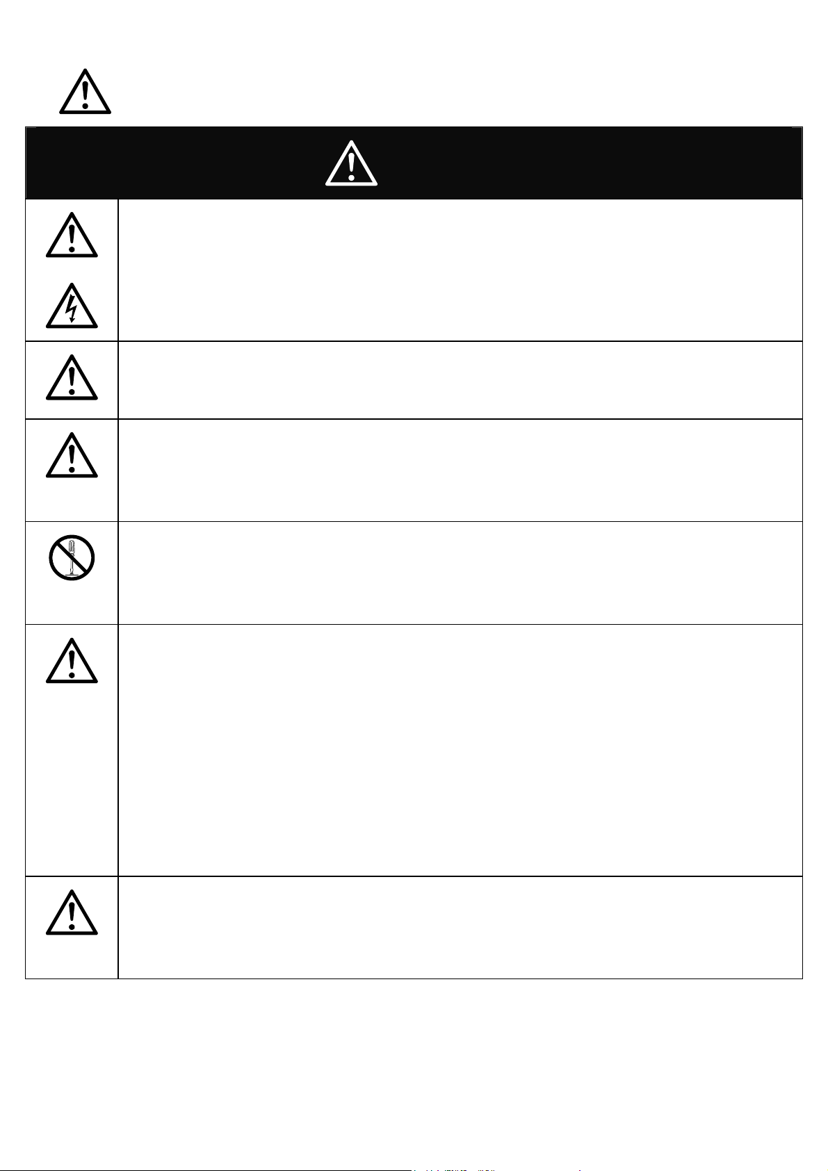
Safe Use of Equipment
2
WARNING
WARNING
To reduce the risks of an electric shock, do not expose inside of this
unit to rain or moisture.
Installation on a rainy day may also cause fog around the capsule.
Installation
Installation shall be done by qualified installer only and should
conform to all local codes.
Ensuring strength of supporting Dome Housing Unit
The unit must be properly and securely mounted to a supporting
structure capable of sustaining the weight of the unit. Recommend
use 3/8” stainless screws x four (4).
Prohibit changes or modifications of equipment
You are cautioned that any changes or modifications not expressly
approved in these instructions could void your authority to operate
this equipment.
Basic Operating Environment Condition
We provide warranty for the products that are installed under normal
outdoor -20°C ~ +50°C conditions. We are unable to provide warranty
for the products which are installed indoor and exposed to constant
high temperature over +50°C and over 90% humidity.
Operating temperature and humidity of camera varies from camera to
camera. You are requested to confirm to camera specification with
camera manufacturer and housing specification with us in advance.
i.e. -20°C or below, you are requested to use additional heater and
+50°C or above you are requested to use two blowers and Sunshield.
Fasten wires tightly.
Attention:
Keep wires away from the Fan / Heater, and do not disturb
Fan/Heater’s performance
Page 4

Table of contents
3
1. AXIS 214 PTZ network camera housing installation………………………..P.4
2. AXIS 215 PTZ network camera housing installation……………………..…P.6
3. AXIS 233D PTZ network dome camera Housing installation……………...P.8
4. AXIS P55XX series PTZ network dome camera Housing installation…....P.10
5. AXIS Q6034 PTZ network dome camera Housing installation………...….P.12
6. Installation of FC-9002 Pole Mount Bracket and Dome housing………….P.14
7. Installation of FC-9005 Ceil Mount Bracket and Dom e housing …..….…..P.15
8. Installation of FC-9006 Ceil Mount Bracket and Dom e housing …….....…P.16
9. Installation of FC-9007 Corner Adapter with Wall Mount Bracket and Dome
housing……………………………………………………………………….….P.17
10. Installation of FC-9008 Corner Adapter with Wall Mount Bracket and Dome
housing ………………………………………………………………….………P.18
11. Installation of FC-900 9N Wall Mount Bracket and Dome housing …….....P.19
12. Installation of FC-9009 Wall Mount Bracket and Dome housing……….…P.20
13.Installation of FC-9011 Ceil Mount Bracket and Dome housing……….…..P.21
14.Dimensions …………………………….………….....................……………..P.22
Page 5
1 AXIS 214 PTZ network camera Housing installation
4
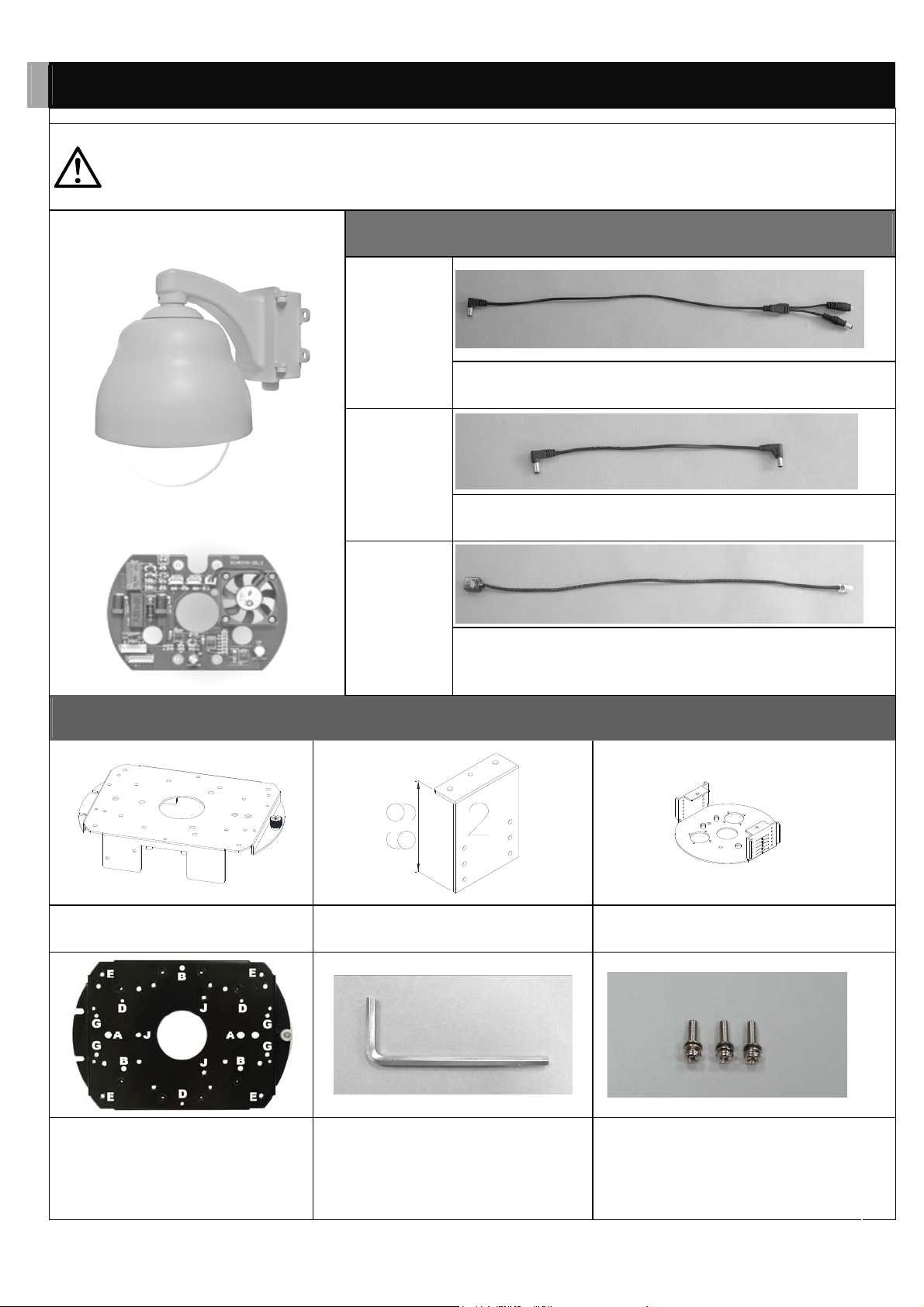
The unit must be properly and securely mounted to a supporting
WARNING
structure capable of sustaining the weight of unit. Recommend use
stainless screws.
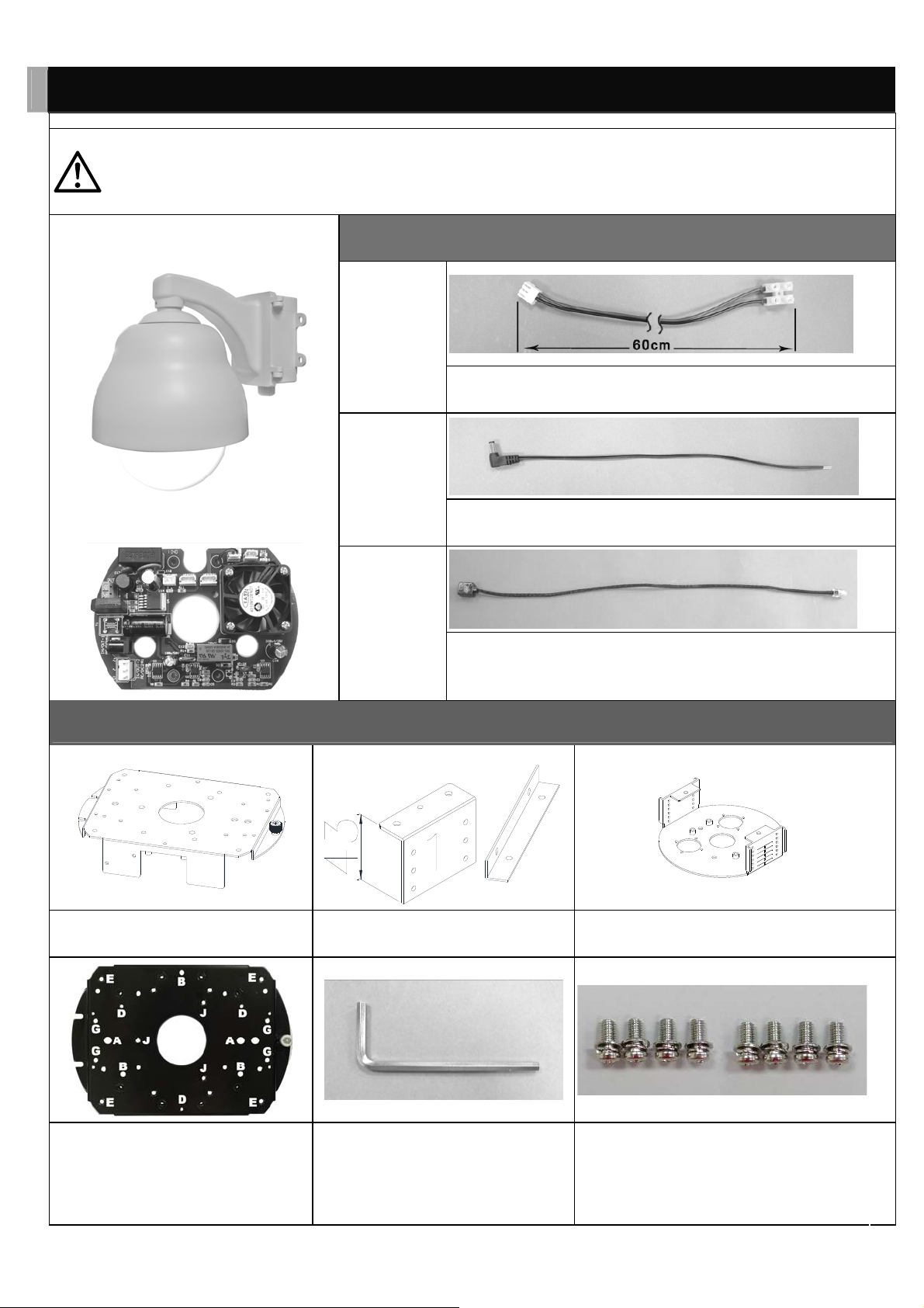
9” dome housing
DC12V Fan+Heater
Cables
L603
L704
L705
Power cable to PC board and external power supply
Power cable to PC board and PTZ network camera
Network extension cable to internet
Component Parts for Assembly
Square-shaped upper board No. 2 side board Round-shaped bottom board
Screw the camera on, through hole B,
with washer in the back
No. 3 Allen Key ( for cover and wall
mount bracket tighten)
3x12 Double Washer screws for
camera to Square-shaped upper
board,
Page 6
5
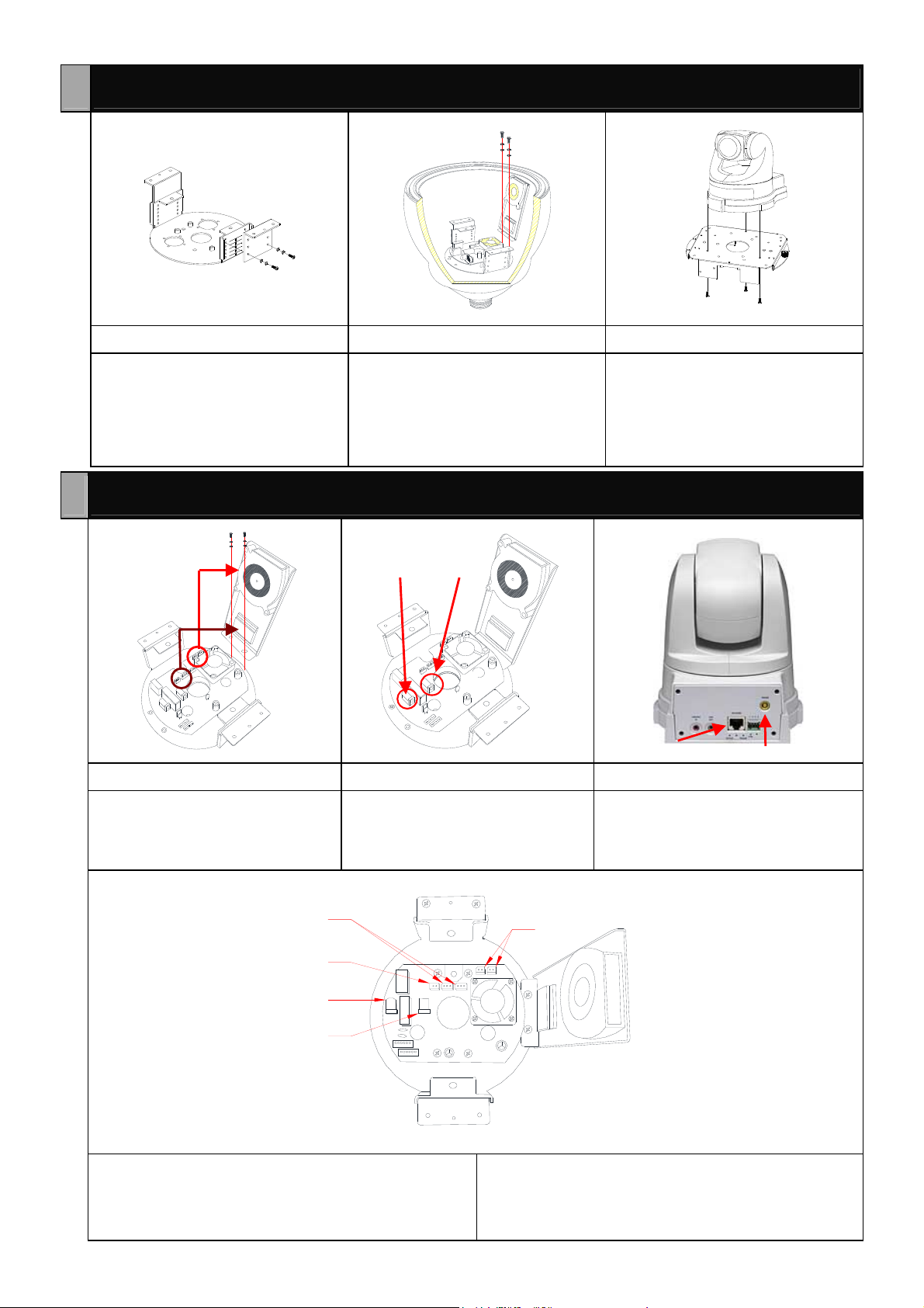
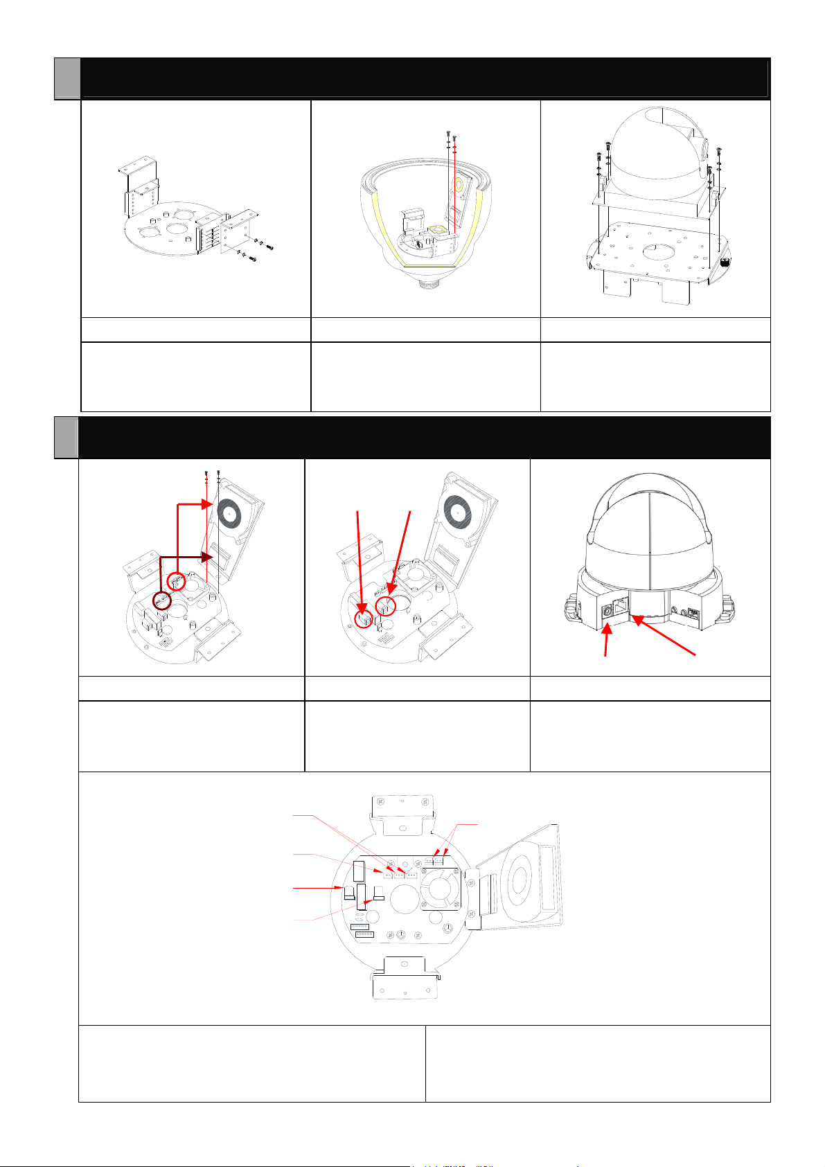
Assembly Steps of the Camera and the Dome Housing
1-1-1 1-1-2 1-1-3
Fix No. 2 side board (Hole 2) to the
round-shaped bottom board (Hole 5)
with 3x8 Double Washer screws.
Use 4x8 double washer screws to
Fix Fan/Heater side board on
Round-shaped bottom board,
connect power cable to Fan/Heater
Fix screws on back of
square-shaped upper board which
go through from back to front to fix
the camera on the square-shaped
upper board (Hole B) with 3x12
double washer screws.
Assembly Steps of the Cables
L704 L603
1-2-1 1-2-2 1-2-3
Use 4x8 double washer to Fix
Fan/Heater side board on
Round-shaped bottom board,
connect power cable to Fan/Heater
Connect L603 to the PC board.
Connect L704 to the PC board.
Connect L704 and L705 to the
camera. Cables used for camera.
L705 L704
2
3
4
1
5
1. DC 12V FAN
2. DC 12V HEATER
3. H/SENSER
4. DC 12V OUT
5. DC 12V IN
Page 7
6
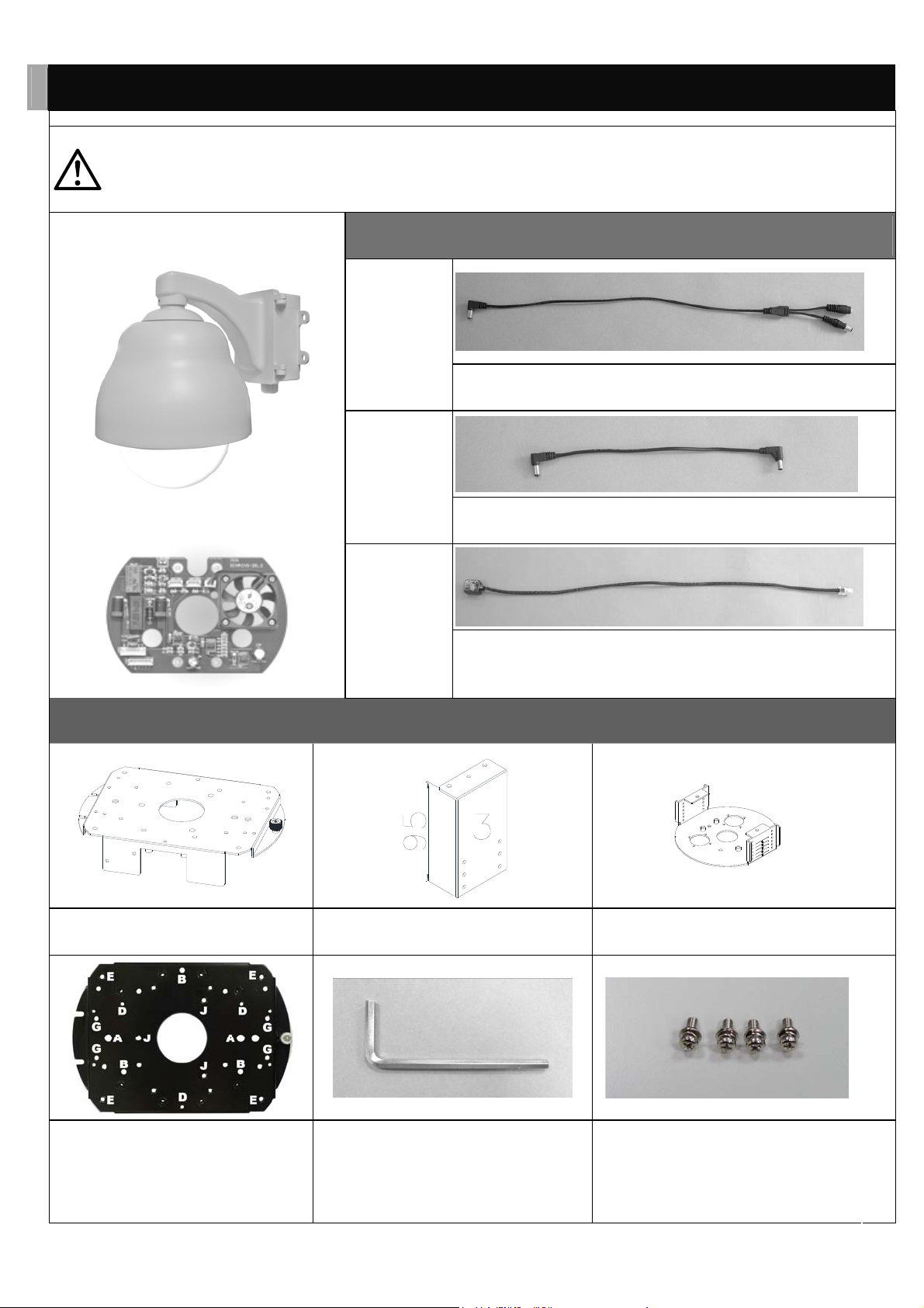
2 AXIS 215 PTZ network camera Housing installation
The unit must be properly and securely mounted to a supporting
WARNING
structure capable of sustaining the weight of unit. Recommend use
stainless screws.
9” dome housing
DC12V Fan+Heater
Cables
L603
L704
L705
Power cable to PC board and external power supply
Power cable to PC board and PTZ network camera
Network extension cable to internet
Component Parts for Assembly
Square-shaped upper board No. 3 side board Round-shaped bottom board
Screw the camera on, through h ole G,
with washer in the back
No. 3 Allen Key ( for cover and wall
mount bracket tighten)
4x10 Double Washer screws for
camera to Square-shaped upper
board,
Page 8
7
Assembly Steps of the Camera and the Dome Housing
2-1-1 2-1-2 2-1-3
Fix No. 3 side board (Hole 1) to the
round-shaped bottom board (Hole 6)
with 3x8 Double Washer screws.
Use 4x8 double washer screws to
Fix Fan/Heater side board on
Round-shaped bottom board,
connect power cable to Fan/Heater
Fix screws on front of square-shaped
upper board to fix the camera on
square-shaped upper board (Hole G)
with 4x10 double washer screws.
Assembly Steps of the Cables
L704 L603
2-2-1 2-2-2 2-2-3
Use 4x8 double washer to Fix
Fan/Heater side board on
Round-shaped bottom board,
connect power cable to Fan/Heater
Connect L603 to the PC board.
Connect L704 to the PC board.
Connect L704 and L705 to the
camera. Cables used for camera.
L704 L705
2
3
4
1
5
1. DC 12V FAN
2. DC 12V HEATER
3. H/SENSER
4. DC 12V OUT
5. DC 12V IN
Page 9
8
3 AXIS 233D PTZ network dome camera Housing installation
The unit must be properly and securely mounted to a supporting
WARNING
structure capable of sustaining the weight of unit. Recommend use
stainless screw s.
9” dome housing
AC24V Fan+Heater
Cables
L605P-2
L704P-2.0
L705
Power cable to PC board and external power supply
Power cable to PC board and camera
Network extension ca ble to internet
Component Parts for Assembly
Square-shaped upper board No. 1 side board & L board Round-shaped bottom board
Screw the camera on, through hole E,
with washer in the back
No. 3 Allen Key ( for cover and wall
mount bracket tighten)
4x10 Double Washer screws for camera
to Square-shaped upper board,
Page 10

9
Assembly Steps of the Camera and the Dome Housing
3-1-1 3-1-2 3-1-3
Fix No. 1 side board (Hole 1) to the
round-shaped bottom board (Hole 5)
with 3x8 Double Washer screws.
Fix screws on front of square-shaped
upper board to fix the L board on
square-shaped upper board (Hole E)
with 4x10 double washer screws.
Fix the camera to the L board with
4x10 double washer screws.
Assembly Steps of the Cables
L704P-2.0 L605P-2
3-2-1 3-2-2 3-2-3
Use 4x8 double washer to Fix
Fan/Heater side board on
Round-shaped bottom board,
connect power cable to Fan/Heater
Connect L605P-2 to the PC board.
Connect L704P-2.0 to the PC board .
Connect L704P-2.0 and L705 to the
camera. Cables used for camera.
L705 L704P-2.0
2
3
4
1
5
6
1. DC 12V FAN
2. AC 24V HEATER
3. H/SENSER
4. DC 12V OUT
5. AC 24V OUT
6. AC 24V IN
Page 11

10
4 AXIS P55XX series PTZ network dome camera Housing installation
The unit must be properly and securely mounted to a supporting
WARNING
structure capable of sustaining the weight of unit. Recommend use
stainless screws.
9” dome housing
AC24V Fan+Heater
Cables
L605P-2
L704P-2.0
L705
Power cable to PC board and external power supply
Power cable to PC board and camera
Network extension cable to internet
Component Parts for Assembly
Square-shaped upper board No. 2 side board Round-shaped bottom board
Screw the camera on, through hole J,
with washer in the back
No. 3 Allen Key ( for cover and wall
mount bracket tighten)
4x10 Double Washer screws for
camera to Square-shaped upper board,
Page 12

11
Assembly Steps of the Camera and the Dome Housing
4-1-1 4-1-2
Fix No. 2 side board (Hole 2) to the
round-shaped bottom board (Hole 5)
with 3x8 Double Washer screws.
Fix screws on front of square-shaped upper board to fix the camera base
on square-shaped upper board (Hole J) with 4x10 double washer screws.
Then tighten camera on camera base.
Assembly Steps of the Cables
L704P-2.0 L605P-2
4-2-1 4-2-2 4-2-3
Use 4x8 double washer to Fix
Heater side board on Round-shaped
bottom board, connect power cable
to Heater
Connect L605P-2 to the PC board.
Connect L704P-2.0 to the PC board .
Connect L704P-2.0 and L705 to the
camera. Cables used for camera.
L705 L704P-2.0
1. DC 12V FAN
2. AC 24V HEATER
3. H/SENSER
2
3
4
5
6
1
4. DC 12V OUT
5. AC 24V OUT
6. AC 24V IN
Page 13

12
5 AXIS Q6034 PTZ network dome camera Housing installation
The unit must be properly and securely mounted to a supporting
WARNING
structure capable of sustaining the weight of unit. Recommend use
stainless screws.
9” dome housing
AC24V Fan+Heater
Cables
L605P-2
L704P-2.0
L705
Power cable to PC board and external power supply
Power cable to PC board and camera
Network extension cable to internet
Component Parts for Assembly
Square-shaped upper board No side board needed Round-shaped bottom board
Screw the camera on, through hole J,
with washer in the back
No. 3 Allen Key ( for cover and wall
mount bracket tighten)
4x10 Double Washer screws for
camera to Square-shaped upper board,
5x10 Double Washer screws for
Square-shaped upper board to
Round-shaped bottom board
Page 14

13
Assembly Steps of the Camera and the Dome Housing
5-1-1 5-1-2
Use 4x8 double washer screws to
Fix Heater side board on
Round-shaped bottom board,
connect power cable to Heater
Fix screws on front of square-shaped upper board to fix the camera base
on square-shaped upper board (Hole J) with 4x10 double washer screws.
Then tighten camera on camera base.
Assembly Steps of the Cables
L704P-2.0 L605P-2
5-2-1 5-2-2 5-2-3
Use 4x8 double washer to Fix
Heater side board on Round-shaped
bottom board, connect power cable
to Heater
Connect L605P-2 to the PC board.
Connect L704P-2.0 to the PC board .
Connect L704P-2.0 and L705 to the
camera. Cables used for camera.
L705 L704P-2.0
1. DC 12V FAN
2. AC 24V HEATER
3. H/SENSER
2
3
4
5
6
1
4. DC 12V OUT
5. AC 24V OUT
6. AC 24V IN
Page 15

14
6 Installation of FC-9002 Pole Mount Bracket and Dome housing
6-1 6-2-1 6-2-2
FC-9002 Pole Mount Bracket
For installation with FC-9009 +
FC-9010 (wall mount bracket and
power box), screw FC-9010 power
box on FC-9002 Pole Mount Bracket
For installation with FC-9009N wall
mount bracket, screw FC-9009N on
FC-9002 Pole Mount Bracket
6-3 6-4
Thread the hoop through FC-9002 Fasten hoop tightly with flathead
screwdriver
Page 16

15
7 Installation of FC-9005 Ceil Mount Bracket and Dome housing
7-1 7-2 7-3
Fix FC-9010 power box on ceil Twist and Tighten the Pole to the
Top of FC-9005
Insert cables through power box
and FC-9005, buckle up the safety
rope, and then tighten up screws
7-4 7-5 7-6
Fix dome housing with FC-9005
bracket
Fix camera to dome housing and
connect the cables
Use Hex Head Cap nut to fix cover
and dome housing
Page 17

16
8 Installation of FC-9006 Ceil Mount Bracket and Dome housing
8-1 8-2 8-3
Top of FC-9006 Pendant Mount
Bracket
Twist and Tighten the Pole
clockwise to the Top of FC-9006
(Two HEX HEAD CAP SCREWS
are already installed on Pole), use
Allen Key to tighten the screws. .
Insert cables through FC-9006
8-4 8-5 8-6
Fix FC-9006 bracket on the ceil Assemble the dome housing and the
bracket, and use Allen Key to fix
screws tightly. Fix camera to dome
housing and connect the cables
Use Hex Head Cap nut to fix cover
and dome housing
Page 18

17
Installation of FC-9007 Corner Adapter with Wall Mount Bracket and
9
Dome housing
9-1 9-2 9-3
FC-9007 Exterior Angle 90°
Corner Adapter Part1
FC-9007 Exterior Angle 90° Corner
Adapter Part2
Join FC-9007 Part1 and Part2
together
9-4 9-5 9-6
Tighten Hex Head Cap screws
clockwise
Then fix whole FC-9007 Exterior Angle
90° Corner Adapter on the wall
Fix Wall Mount Bracket on FC-9007
Corner Adapter with washer in the front
and the screw nut in the back
Page 19

18
Installation of FC-9008 Corner Adapter with Wall Mount Bracket
10
and Dome housing
10-1 10-2 10-3
FC-9008 Interior Angle 90° Corner
Adapter Part1
FC-9008 Interior Angle 90° Corner
Adapter Part2
Join FC-9008 Part1 and Part2
together
10-4 10-5 10-6
Tighten Hex Head Cap screws
clockwise
Then fix whole FC-9008 Interior
Angle 90° Corner Adapter on the
wall
Fix Wall Mount Bracket on FC-9008
Corner Adapter with washer in the
front and the screw nut in the back
Page 20

19
11 Installation of FC-9009N Wall Mount Bracket and Dome housing
11-1 11-2 11-3
FC-9009N Wall Mount Bracket
Put cables through bracket Fix bracket on wall
11-4 11-5 11-6
Assemble the dome housing and the
bracket, and use Allen Key to fix
4x10 screws tightly.
Fix camera to dome housing and
connect the cables
Use Hex Head Cap nut to fix cover
and dome housing
Page 21

20
12 Installation of FC-9009 Wall Mount Bracket and Dome housing
12-1 12-2 12-3
Fix mounting holder to the Dome
housing.
Put cables through the bracket. Assemble the Dome housing and the
bracket.
12-4 12-5 12-6
Fix camera to dome housing and
connect the cables
Use Hex Head Cap nut to fix cover
and dome housing
Fix the power box to the wall or to the
column.
12-7 12-8
Have the bracket hooked up to the
tenon of the power box.
Buckle up the safety rope and then
connect cables with the outward
cables.
12-9
The completed assembl y.
Page 22

21
13 Installation of FC-9011 Ceil Mount Bracket and Dome housing
13-1 13-2 13-3
Twist and Tighten the Pole to the
Top of FC-9011
Fix FC-9011 on Ceil Insert cables through FC-9011
13-4 13-5 13-6
Fix dome housing with FC-9011
bracket
Fix camera to dome housing and
connect the cables
Use Hex Head Cap nut to fix cover
and dome housing
Page 23

22
14 Dimensions
133
115
52
14-1 14-2 14-3
FC-29W 9” housing Internal
dimensions
FC-9002 Pole Mount Bracket
FC-9005 Pendant Mount Bracket
100
43
193
175
14-4 14-5 14-6
FC-9009N or FC-9009 Wall Mount
Bracket dimensions
FC-9006-30 30cm Pendant Mount
Bracket dimensions
14-7 14-8 14-9
FC-9008 Interior Angle 90° Corner
Adapter dimensions
FC-9010 Power Box dimensions
FC-9007 Exterior Angle 90° Corner
Adapter dimensions
52
FC-9011 Pendant Mount Bracket
125
71
100
180
125
172
219
Page 24

23
IMPORTANT SAFEGUARDS
1. Read Instructions – All the safety and operating instructions
should be read before operating the unit.
2. Retain Instructions – The safety and operating instructions
should be retained for future reference.
3. Heed Warnings – All warnings on the unit and in the operating
instructions should be adhered to.
4. Follow Instructions – All operating user instructions should be
followed.
5. Electrical Connections – Only a qualified electr ician should make
the electrical connections.
6. Attachments – Do not use attachments not recommended by the
product manufacturer as they may cause hazards.
7. Cable Runs – All cable runs must be within permissible distance.
8. Mounting – This unit must be properly and securely mounted to a
supporting structure capable of sustaining the weight of the unit.
Accordingly:
a. The installation should be made by qualified installer.
b. The installation should be in compliance with local codes.
c. Care should be exercised to select suitable hardware to install
the unit, taking into account both the composition of the
mounting surface and the weight of the unit. Be sure to
periodically exami ne the unit and the supporting structure to
make sure that the integrity of the installation is intact. Failure
to comply with the foregoing could result in the unit
separating from the support structure and falling, with
resultant damages or injury to anyone or anything struck by
the falling unit.
SAFETY PRECAUTIONS
CAUTION
RISK OF
CAUTION: TO REDUCE THE RISK OF
ELECTRICA L SHOCK, DO NOT EXPOSE
COMPONENTS TO WATER OR MOISTURE.
ELECTRIC SHOCK!
The lightning flash with an arrowhead
symbol, within an equilateral triangle, is intended
to alert the user to the presence of non-insulated
“dangerous voltage” within the product’s
enclosure that may be of sufficient magnitude to
constitute a risk of electric shock to persons.
The exclamati on point within an equilateral
triangle is intended to alert the user to presence of
important operating and maintenance (servicing)
instructions in the literat ure accom panying th e
appliance.
UNPACKING
Unpack carefully. Ele ctri c compon ents can be damaged if
improperly handled or dropped. If any of the products appears to have
been damaged during the shipment, replace it properly in its carton and
notify the shippe r.
Be sure to save:
1. The shipping carton and packaging material. They are the safest
material in which to make future shipments of the equip ment
2. The Installation and Operating Instructions.
Page 25

Page 26

Page 27

Page 28

 Loading...