

Page 1
INSTRUCTION MANUAL
DV426/DV426-4G
4 Channel DVR Black Box Recorder
with WiFi, GPS & SATA SSD 2YEAR WARRANTY
SPECIFICATIONS
- Record Type Quad
- 4G: DV426-4G Only
- GPS: Yes
- WiFi: Yes
- Vehicle Tracking: Yes
- Max Resolution: 1920 x 1080 (100FPS)
- Real Time Recording: Yes - Auto or Scheduled
- G-Sensor: Yes
- Motion Detection: Yes
- AV Output: VGA, CVBS (RCA Adaptor Included)
- Monitor View: Normal/Mirror Image Selectable
- Video Compression: H.264 for High Quality Video
- Reverse Camera Compatible: Yes
- Camera Connection: 4 x 4-Pin
- Lockable Storage: Yes - 1 x 2.5” SATA SSD (Not Inc), 1 x 128GB SD Card (Not Inc)
- Operating Voltage: 9 to 36V
- Alarm Inputs: 6 CH
- Alarm Outputs: 2 CH
- Ignition Signal: Yes
- Speed Signal: Yes
- Timer Recording: Yes
- Adjustable Frame Rate & Bit Rate: Yes
- User Password Protection: Yes
- Operating Temperature: -20°C to 70°C
- Power Consumption: 15W (Working)
- Dimensions: 183 x 38 x 148mm
- Includes: Keys, Antenna Kit, Remote Control, Power Cable, Alarm Cable, USB Cable
1
Page 2

1. Specifications
Operating system
Linux
Operating interface
Graphical menu operation interface(OSD)
Video permission
Administrator & user setting
Video input
4 x 1080P analog high definition
CVBS output
1CH 6pin aviation
VGA output
1CH VGA output, 1080P
HDMI output
NULL
Video display
1 、2、3、 4
Video standard
Compression
H.264 main profile
Audio input
4 channels
Audio output
1 channel
Record format
Synchronized video & audio recor din g
Audio compression
ADPCM
Image resolution
Max 4 x 1080P(1920*1080)
Video bit rate
64kbps~4Mbps/channel
Storage
56~2700MB/(channel*hour)
Audio bit rate
32kbps
Storage
2.5 inch SATA SSD x 1, max 2TB; SD card x
Alarm input
6 channels
Alarm output
2 channels, 1 buzzer
Motion detection
High/low/off sensitivity adjustable
IR
1 channel
RS232
1 channel for RFID
RS485
1 channel for Panic Button
CAN
2 channels
RJ45
1 channel
USB mini-B
1 channel
USB2.0
2 channels
4CH HD DVR
System
Video
Audio
Digital
processing &
storage
PAL: 25FPS, NTSC: 30FPS
1, max 128GB
connector output PAL/NSTC
Alarm
Interface for
communication
1channel for copying file(SSD、SD) and firmware
upgrade
1 channel for copying SSD file(on ly for c onnecting
to computer USB)
2
Page 3

USB3.0 NULL
WIFI hotspot/AP
optional
/Gyroscope
Windows client
Web portal
Available
Input
Clock
Built-in clock, Calendar
Wireless
GPS
G-Sensor
Software
Power
Electrical spec
2G/3G/4G optional
WIFI optional
Internal or external GPS/GLO N AS S module, coordinate/speed can be
encoded in video stream and upload ed to ser ver by wireless
communication
Available six axis sensor
Available
iOS client Available
10~32V
Current Draw 12V@3.5A
Max Power
Consumption
Standby Power
Consumption
Operating temp. &
humidity
Super Capacitor Available
60W
100mW
-20~70 degree/ <100%
3
Page 4

SENSOR-I
SENSOR-I
SENSOR-I
SENSOR-I
SENSOR-I
SENSOR-I
Reversal
Brake
2. Precautions
1、Motion detection functi on is set to OFF by default. Al arm fil es wi ll be create d
when there’s motion detected when set ON.G-sensor recording is
recommended to set ON during dri vi ng for em erg ency recor ding use. G-sensor
level is optional.
2、If the DVR can not boot up, try to remove all storage disks from the DVR,
and then restart the DVR to check whether it can boot normally or not.
3、Make sure the yellow ACC wire is connected to the ignition wire and the
red V+ wire to the positive pole of the battery. In this case, the DVR can
continue to record for sometime after the vehicle engine is off. If the ACC wire
(the yellow one) and the V+ wire (the red one) are connected directly to the
positive pole of the battery, the DVR will still work even if the vehicle is not
started. If the ACC wire and the V+ wire (the r ed on e) ar e c on nected directly to
the ignition wire of the vehicle, the recording files will be easily damaged when
the vehicle engine is off.
4、All the disks must be formatted on the DVR before use.
5、The login user name can not be changed. Password is editable.
6、All types of video files including event recording files will be overwritten by
default. If not to overwrite the event files, set [Event Rec. Lock] to OFF. in the
menu of [Event Rec.] under [Record].
7、
The corresponding types of SENSOR-IN1~6 on the trigger line are as
follows:
N1
N2
ALARM INPUT 1~4
N3
N4
N5
input
N6
input
4
Page 5

3. Main Features
Appearance
Smaller than the previous models.
Controlled by touch screen
All settings and operations could be done through the monitor if connected with
the suggested touch screen.
Video and Audio
4 channels * 1080p, 4 video inputs w it h audio
1 CVBS output(1 * 6 PIN OUT) with audi o
Support IPC camera
Recording
4-CH Video & Audio Recorder (with i mag e r es olution up to 1920 X 1080), and
with G-sensor data and GPS data
Multiple recording modes: pow er on r ecor ding, normal recording, schedule
recording, event recording (i.e., G-sensor recording, speed recording, motion
detection recording, Alarm r ecor di ng 1~6, Panic button recording). Cyclic
recording and 15 seconds pre-recording are supported.
Recording files are stored in the SSD or SD card. Cyclic recording is optional.
Real-time recording of license plate numbers, dr iv ing speed,G-sensor/Gyroscope
6D accelerated speed, longitude and latitude, and GPS tracks.
Preview and Playback
Support single channel, or 4 channels audio and video play simultaneously.
Support searching recording files by r ecor ding date, recording type.
Able to drag the progress bar when p lay ing back.
Indicate recording status, alar m stat us .
Storage Types
Support SSD, SD cards (SDHC, SDX C)
If both SSD and SD card are used for stora ge, SSD will be preferred. SD card
can be stored only when SSD is not insta lled.
SD card can be removed convenient ly when not in recording or playing status.
Backup
5
Page 6

Support USB disk or USB hard disk to backup copy of recording files.
Network
Support LAN, WI-FI, 2G/3G / 4G, automatic network switching;
LAN / Wi-Fi / Cellular connection (de fa ult priority: LAN > Wi-Fi > Cellular); auto
switch to LAN / Wi-Fi connection when available to save Cellular traffic.
LAN, WI-FI and 2G/3G/4G have the priority of connections which wi ll switch
automatically to save 2G/3G / 4G dat a;
Wi-Fi supports S TATION and AP mode, in which Wi-Fi AP mode supports
mobile direct connection devices, w hich is convenient for preview and
configuration on mobile;
Support remote real-time v ideo st r eam, image stream pre-view function
Support alarm recording, alar m information, log information, GPS trajector y
automatic upload function, which is convenient for vehicle abnormal conditio ns
analysis and vehicle traject or y tracking;
Support remote configurat ion, re mot e upgr ade w hich ac hiev e rea l re mote con t rol
function;
Support PC Windows Client, mob ile IOS and Android APP. Users can remotely
monitor vehicles on computer or mo bi le phone
Alarm
6 channels alarm inputs, one c hannel buzzer output and 2 channels alarm
outputs
Over-speed alarm and accelerated-speed alar m
Motion detection alarm
G-sensor alarm
Panic button alarm
Charger
5V, 1.5A output from the USB interface to mobile devices, such as mob ile phone.
Security
User password protection. The D VR can only be accessed with correct
password.
Support account management.
6
Page 7
4. Wiring Diagram
BLANK
5. Connection - Front Panel
7
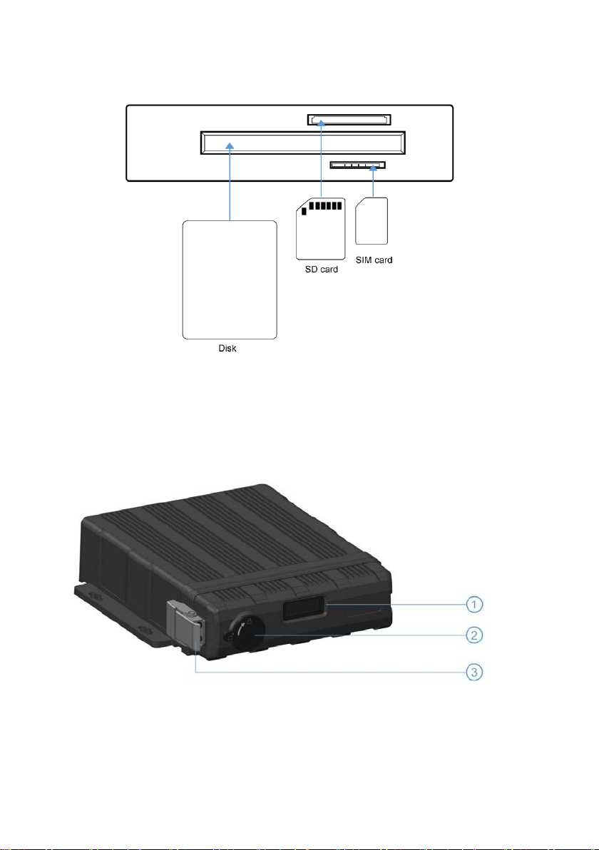
Page 8

① LED Indicators ⑤ IR Receiver
② Electronic lock
③ Front Cover Buckle ⑦ SSD Slot
④ USB3.0 Interface ⑧ SIM Card Slot
⑥ SD Card Slot
5.1 LED
NULL
5.2 Electronic Lock
Close the front cover and turn the groove by the key to the icon “off”, so as to
prevent hard disk drive fro m movin g out. Or t urn to the ic on “on” t o open t he fr ont
cover.
Electronic Lock Function: DVR will stop recording and buz zer will beep when the
front cover is open.
5.3 Remote Receiver
The IR Receiver is for the DV R to receive command from the remote control.
Remote control instructions:
8
Page 9

5.5 SSD card slot
Hard disk Type: SSD (Max. capacity: 2T )
Size: 2.5 inches(70*100*7mm).
5.4 SD card slot
SD card type: The maximum capacity of each card is 128G.
Insert、remove SD card
Step 1: Use the key to unlock and open front plate
Step 2: Insert SD card to SD card slot
9
Page 10
Wi-Fi Connector
Step 3: Close the front plate and use the key to lock
5.6 USB Slot
USB 2.0/3.0, Max. Capacity 2T
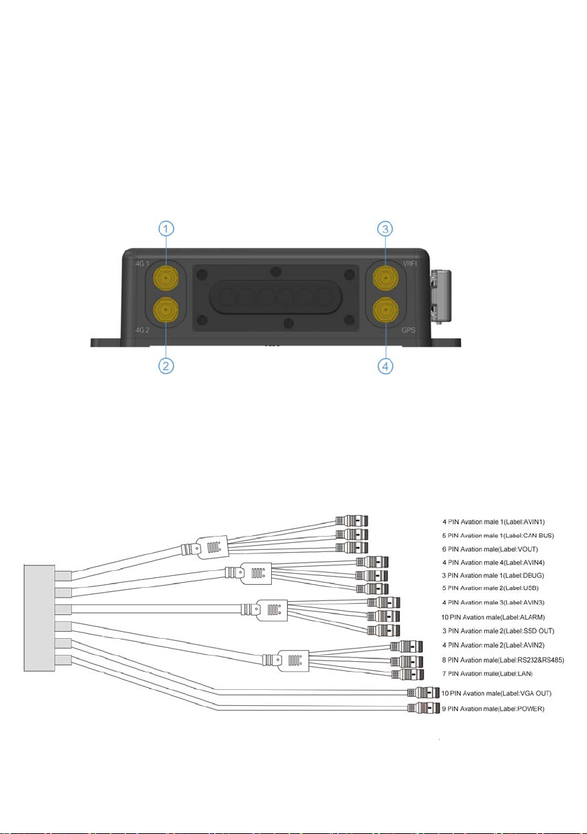
6. Back Plate
① Cellular Connector, TX/RX
② Cellular Diversity Connector, Rx ④ GPS Connector
③
10
Page 11
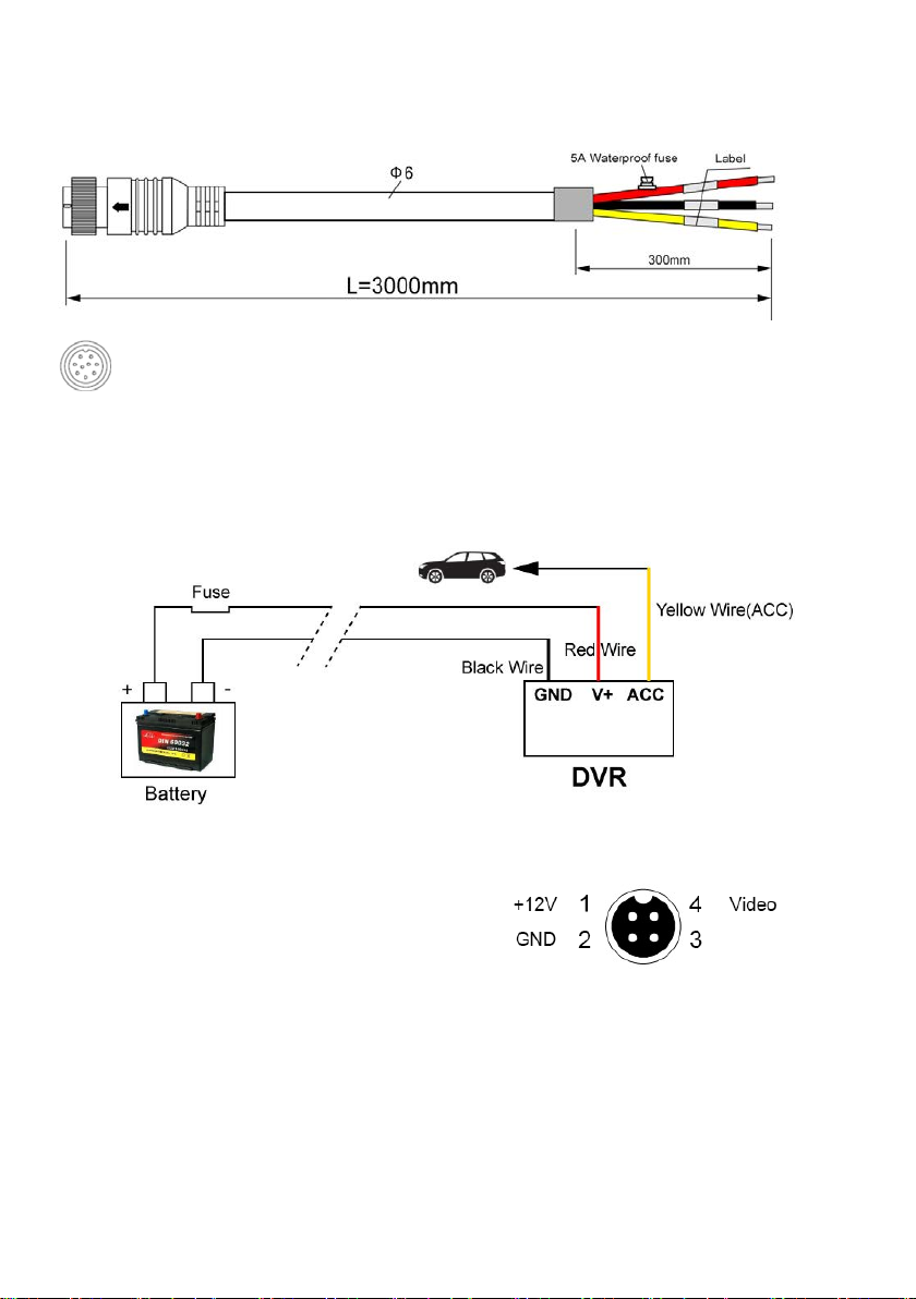
6.1 Power
power input
9 PIN Avation female connect to 9 PIN Avation male on the DVR
Connection
Connect ignition wire to yellow ACC wire of DVR, battery Positive to V+(Red wire),
Negative to GND(black wire)
6.2 Camera(AVIN 1~4 )
See below 4 cameras diagram.
How to connect cameras
Connect 4 cameras on below cable which connects to back plate of DVR
Audio
11
Page 12
Connect No.1 camera to AVIN1 4PIN Aviation male
Connect No.2 camera to AVIN2 4PIN Aviation male
Connect No.3 camera to AVIN3 4PIN Aviation male
Connect No.4 camera to AVIN4 4PIN Aviation male
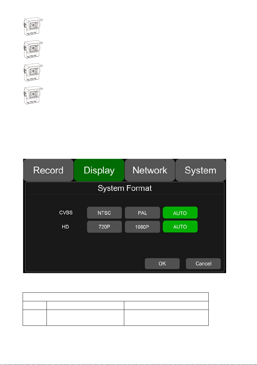
6.3 LCD monitor
EDID (Extended Display Identi fi cat i on Data) is automatically acquired when power is
turned on.Output resolution of the LCD monitor can be selected. Settings are as follows:
AUTO system format will be recognized as above
System Format
CVBS HD
AUTO NTSC/PAL 1080P/720P
10” HD monitor introduction (Recommended)
12
Page 13

13
Page 14

Description
HD 10.1"Color monitor
HD 7"Color monitor
Audio output (loudspeaker)
1W
1W
VGA input
1
1
CVBS input
1
1
Max. Brightness
500 cd/m²
450 cd/m²
Minimum Operating
Mirror Function
No
No
159.5mm (H) ×
Consumption
less than 8W
less than 5W
The parameter list of 7/10 inches HD monitor
Features used for HD DVR us ed for HD DVR
Resolution 1024 x 600 (RGB) 1024 x 600 (RGB)
Maximum Number of Cameras 1 1
Audio input 1 1
HDMI input / /
Trigger No No
Contrast
Temperature
Maximum Operating
Temperature
Viewing Angle Monitor U: 70/ D: 50, R/L: 70/70 U: 75/ D:75, R/L: 75/75
Monitor Diameter (mm)
Split Screen No No
6.4 Buzzer
If the DVR is not connected to the monitor, check the DVR's recording status through
the buzzer.
Buzzer will alarm if the DVR is not recording under Normal Mode which is set by
default. To stop the buzzer from alar m ing, check whether the DVR is recording under the
Normal Mode or not.
Buzzer warning functions are as f ol low s
Buzzer beep alarm will last for a while for all types of alarm event recording.
If the Buzzer beeps intermittent ly, it means that the DVR is unable to record.
Different beeping modes st and for different working status as below:
a. If the electronic lock is open: one long beep and one short beep
b. Diskless: one long beep and two short beeps
600:1 800:1
-20ºC, RH 90% -20ºC, RH 90%
+70ºC, RH 90% +70ºC, RH 90%
267mm (W) ×
30mm (T).
Volts 10-32V 10-32V
203mm (W) × 112mm (H)
× 28mm (T).
14
Page 15
c. Disk file system exception : one long beep and three short beeps
d. If disks are normal but the alarm video files are full : two short beeps and one shor t
beep
e. No camera input: two short beeps , and two short beeps after a second
f. If disks are normal but DVR is not in rec ording: two short beeps and three short
beeps
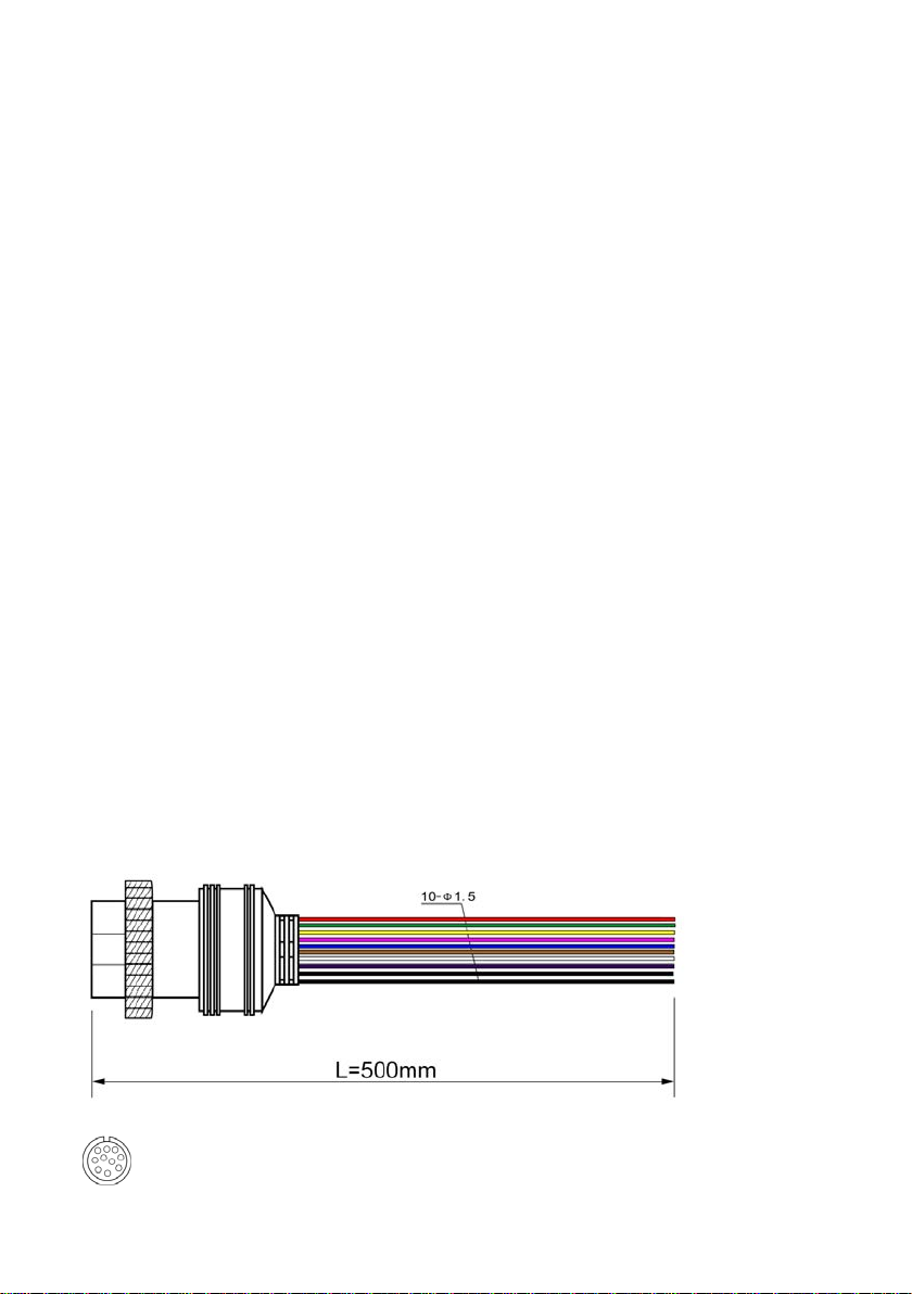
6.5 Alarm Interface
Alarm interface cable
See the picture below
10 PIN female head on the DVR connect t o 10 PIN male head
Pin Definition:
15
Page 16
10 PIN 1 2 3 4 5 6 7 8 9 10
Colour
red
pink
blue
gray
white
purple
green
yellow
black
black
Definition
Alarm
Alarm
Alarm_in
Alarm_in
Alarm_in
Alarm_in
Alarm_in
Alarm_in
out2
1. There are 6 alarm inputs including alarm inputs 1 ~ 4, reversal input, brake input,
out1
which can trigger the alarm recording. . Cursor will be displayed when the alarm
input channel is working. The first 4 on es can be self-defined by user.
6
5
4
3
2
1
GND GND
2. Alarm output 1 and Alarm output 2 are 12V output by default, which can be us ed
as a trigger and need to be set up to co mbine w ith alarm input . You can also
setup BUZZER for the output.
3. If Alarm input 1 is active and combined with Alarm output 1, the Alarm output 1
will output a high-level voltage to trigger other device.
16
Page 17
6 Panic button (Optional)
Overview
The LEDs are used to show the device’s working
status. But when the device is inst al led in the
vehicle, it is not easy to check the LED on the front
panel. Each of the LED indicate s t he
corresponding status. Furthermore, the panic
button on the panel makes it easier to tr igg er al arm
for emergency by bookmarking a ma nual event.
Pin Definition
17
Page 18

8 PIN female head connect to 8 PIN male head(RS232&RS485) on the DVR
LED
LED Color ON OFF
VLoss Amber
Rec
GPS Amber GPS cannot latch Normal Operation
Mem Red
Comm Amber
Power
Error Red Error with device Normal Operation
Event Red
Button
PANIC button, printed as “Bookmark”
Soft
green
Pale
Blue
Any of the cameras have no
signal alarm
Recording Normal driving Not recording
Storage Alarm or no
Storage device
Device is not connected to
server
Device has power Device does not have power
Event-based Recording
(remains lit during Event)
Normal Operation
Normal Operation
Normal operation or device is
not connected to server if this
feature is disabled
Normal Operation
a. When pressed, a manual event w il l be tr iggered.
b. When pressed, the Event LED wil l be temporarily illuminated.
If the PANIC button alarm recording cannot be triggered, check if the alarm
recording button is open as shown be low :
18
Page 19
If the alarm recording was triggered, there will be an alarm sign on the screen, as
shown below:
6.7 Built-in GPS antenna
Built-in GPS antenna soc ket and GPS antenna, as shown in the picture.
19
Page 20
7. The Menu
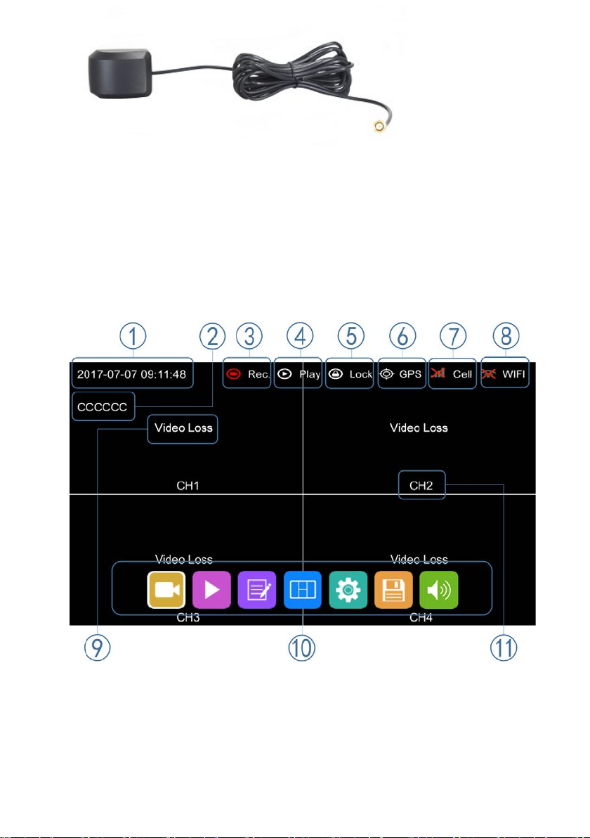
7.1 Menu Introduction
Touch [MENU] on the remote or touch the bottom area, the LOGIN page will be
displayed on the LCD screen. The Short cut Menu wil l be displayed a fter login. If y ou press
[MENU] on the remote or Touch the bottom area again, the Main Menu will be displayed.
① System Time Display
② License plate number Disp lay
③ Recording Sign
The Recording Sign will turn red when rec ording
④ Playback Sign
The Playback Sign will turn red during playback.
20
Page 21
⑤ Electronic Lock Sign
Lock indicator turns red when electronic lock is locked and front c over is closed.
Electronic lock is different from menu lock.
⑥ GPS Sign
The GPS Sign will be flashing when connecting. It will be always ON if successfully
connected.
⑦ Cell Sign
⑧ Wi-Fi Sign
⑨ Video Loss Sign
⑩ Menu
Press [Area 10] to display MENU Si gn
⑪ Channel Name Sign
7.2 Menu Lock
21
Page 22
DVR supports two kinds of permissions: admin permissions and guest
Initial Passwo rd
123
321
permissions
User permissions list
User Name admin guest
Password Modification
yes no
Enter the menu of
Enter all menus
Permissions
Playback,Display mode
switching and Volume
User name cannot be changed, but user password is changeable. (See the
following instructions for chang in g pas sword)
Username admin and password are needed to change the status of Menu lock.
The following picture shows how to change the Menu Lock status from ON to
OFF.
When the status of Menu Lock is On, username admin and password are
needed to enter menus like Record, Playback, Log, System and Disk. With
username guest and password, only the Playback menu can be entered.
22
Page 23
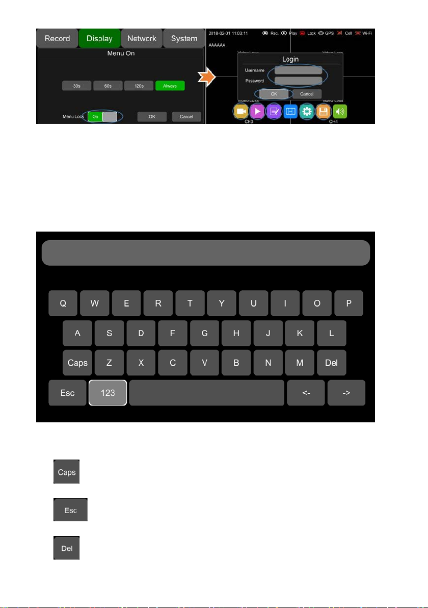
7.3 Keyboard Operation Instructions
:Switch letter case
:Exit the keyboard interface
:Delete the input letters
23
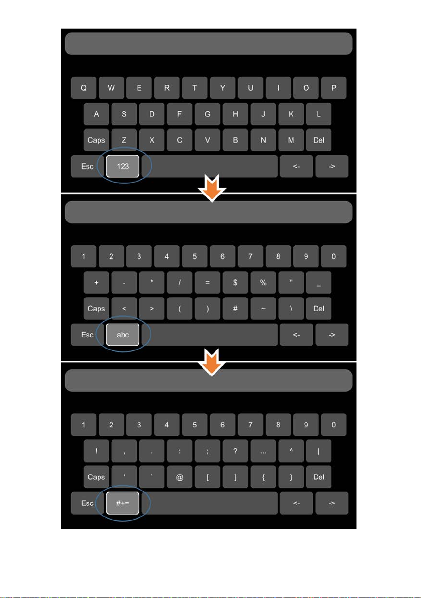
Page 24

:Switch to the numeric interface
:Switch to the English alphabet inter face
:Switch to the special character interface
Character Switching Instructions
24
Page 25
25
Page 26
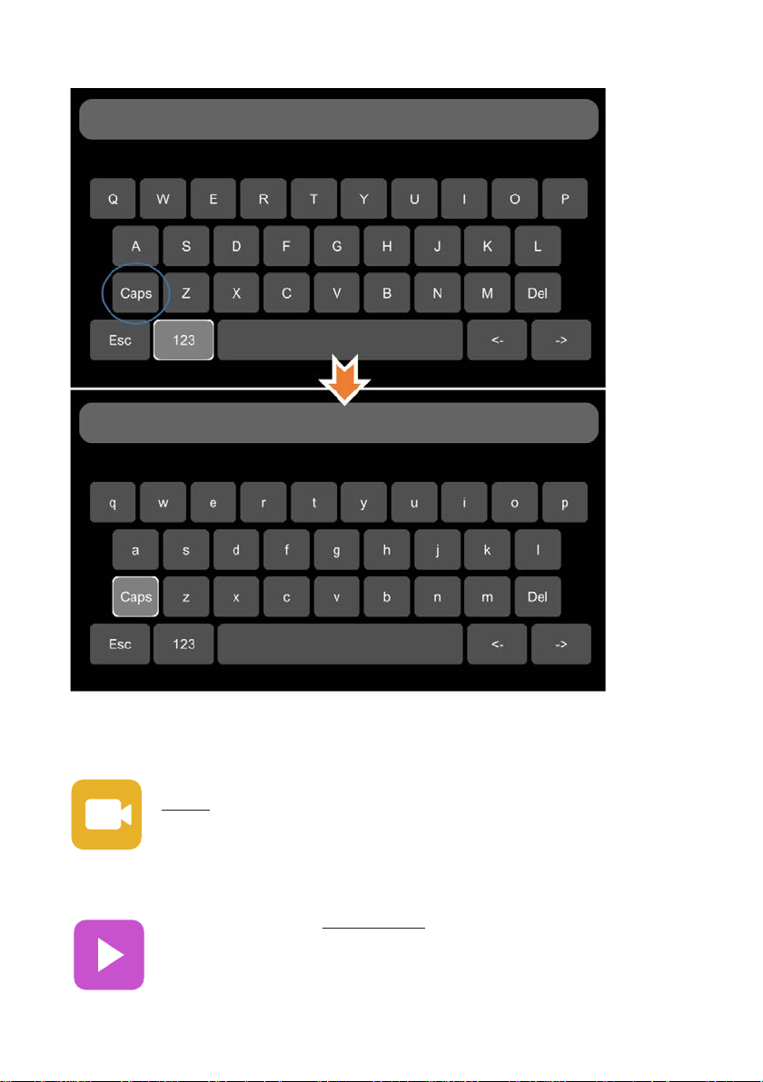
Letter Case Switching Instructions
7.4 Manually Record
Touch this icon to start or stop recording. Video files can be found in the
Normal list of Player menu.
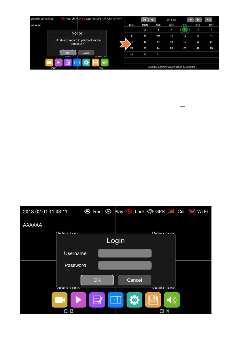
7.5 Playback
Video Playback button: Touch this icon to enter the calendar menu.
Green marked date means it has recording files saved on that day.Select the
date to enter the video file list, then select the file and touch Play icon to play
video. You can select single or multiple videos at a time. Multiple videos can
be played in sequence and can be shifted to the next or the previous one
26
Page 27

G-sensor recording
Event recording setup time
Event list
Speed recording
Event recording setup time
Event list
Panic button recording
Event recording setup time
Event list
Specific operation sees below.
: Search by month
: Search by year
Normal: Normal recording list, including Normal Recording, Power on Recording,
Schedule Recording
Event: Alarm recording list , including alar m rec ordi ng 1~6, M otio n det ectio n rec ording,
G-sensor recording, Speed r ecor ding, Panic button recording
Type Recording Time Co nt r ol Mode View Position
Normal recording Manual control Normal list
Power on recording Manual control Normal list
Schedule recording Pre-setup time Normal list
Alarm recording 1~6 Event recording setup time Event list
Motion detection recording Event recording setup time Event list
Capture: Screenshot list
Play: Play the selected video file s
Export: Export selected video files to USB
27
Page 28

All: Select all video files in this page
Exit: Exit
: Volume adjusting button
: Switch
: Play the previous/next video
: Pause/Resume playing
: Hide the play menu. And press [Area 1] to display.
: Exit playing
7.6 Log
System memo checking, memo output
7.7 Display mode switching
Mode switch button: Touch this ic on t o ent er t he M ode switch interface.
28
Page 29

:One-division mode of Camer a
Left (CH1)
:One-division mode of Camera
Right (CH2)
:One-division mode of Camera
Front (CH3)
:One-div ision mode of Camera
Back (CH4)
29
Page 30

Three-division mode of Camera
Left, Front and Back (CH1, CH3, CH4)
Three-division mode of Camera
Front, Back and Right (CH3, CH4, CH2)
Three-division mode of Camera
Front, Left and Right (CH3, CH1, CH2)
Three-division mode of Camera
Left, Right and Back (CH1, CH2, CH4)
:Two-division mode of Camera
Front and Back (CH3, CH4)
30
Page 31

:Two-division mode of Camera
Left and Right (CH1, CH2)
:Four-division mo de of Camera
Left, Right, Front and Back (CH1, CH2,
CH3, CH4)
:Four-division mode of Camera
Left, Front, Back and Right (CH1, CH3,
CH4, CH2)
7.8 System
:Set the current selected mode as default.
:Exit.
System settings button: Touch System to enter the setup menu. A prompt
dialog will display "Unable to record in set-up mode! Continue?” Touch OK to
enter.
31
Page 32

7.9 Disk
Disk management button: Touch the disk management icon, then y ou can view
the status of SSD, SD card and USB.
32
Page 33

① Disk type
② ALL:The total capacity of disk,free:The remaining capacity of disk
If ALL shows 0.00MB, it means that DVR does not have access to this type of disk
③ Green area shows the capacity of all the recording files in the Normal list
Red area shows the capacity of all the recording files in the Event list
Blue area shows the capacity of all the pictures in the Capture list
Yellow area shows the capacity of all the other files except those above
④ Touch to format the disk.
A di alog bo x displ aying “D isk dat a will be deleted! Continue?”will pop up. Press
OK to start formatting the disk
The following picture is an example of formatting USB2
If the disk cannot be formatted, please check if:
a. There is a disk in the slot
33
Page 34

b. All recordings are set off
c. The FTP button is set off
⑤ It shows that the disk needs to be formatted before use.
All new disks must be formatted before use.
⑥If SSD Out is ON, the recording files in the disks can be exported to computer via
USB cable. Please note that only recor dings files can be exported in this way.
7.10 Volume
Volume : value 0~10, Default value is 5.
34
Page 35

8. Record Setup
8.1 Power On Rec
is set to ON. Default is ON.
The DVR will start recording after power on when 'Power On Rec’
8.2 Cyclic Rec
setting the Cyclic Rec ON. Otherwise, it will stop recording when disk is full.
Overwriting will cover all recording files including Event recording files by default.
New video files will overwrite the prev ious ones w he n disk is fu ll if
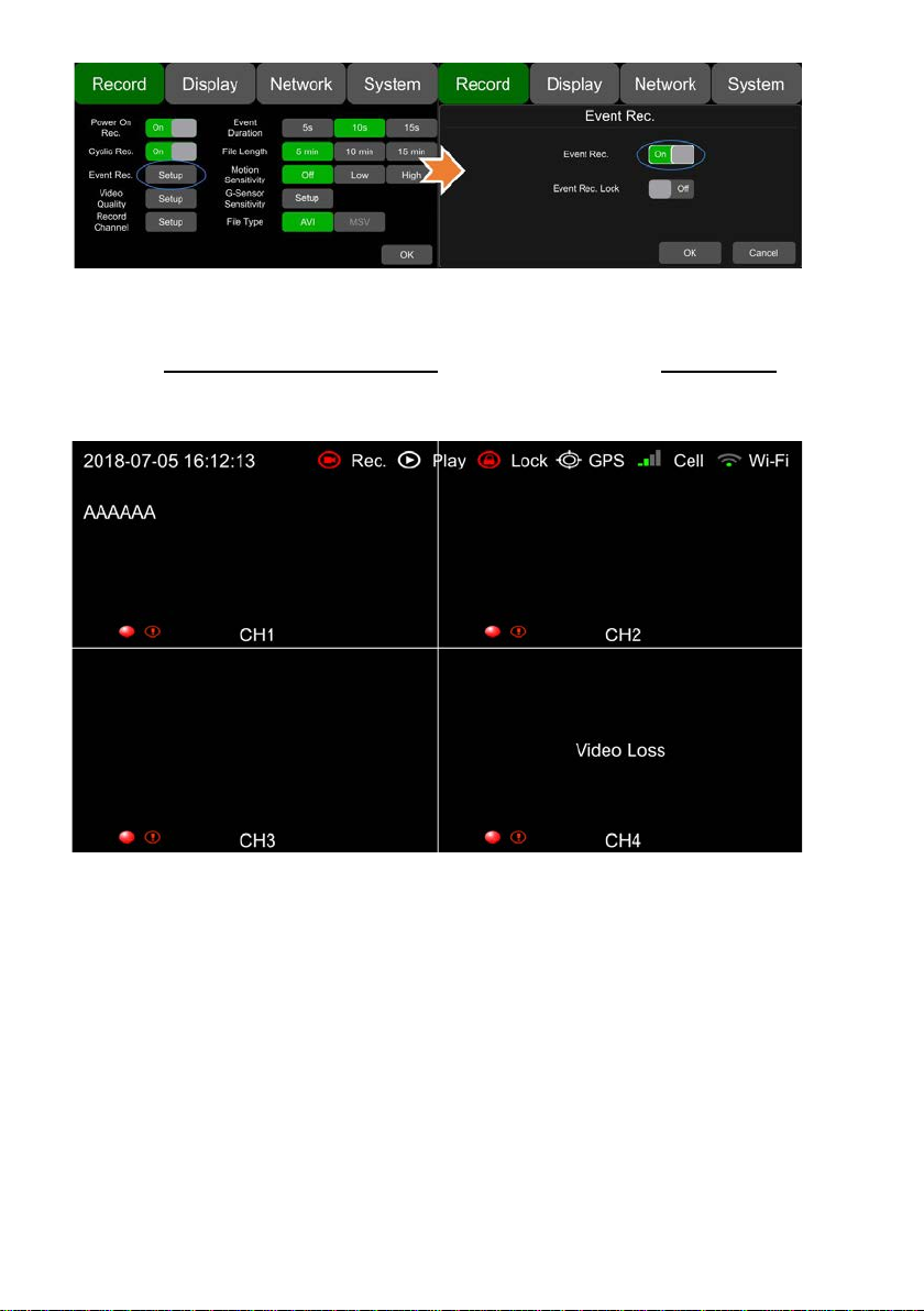
8.3 Event Rec
35
Page 36

Event Rec.:Event recording type includes motion detection triggered alarm, G-sensor
triggered alarm, alarm 1 ~ 6 triggered alarm ,Panic button trigger ed alarm and over speed
alarm. If the Event Rec is ON and corresponding alarm parameters are set, event
recording will be activated when the events above are triggered. If the Event Rec is OFF,
event recording will not be activat ed even if event is triggered.
Event Rec. Lock:
full, new video files will overwrite the previous ones(all recording files except Event
Recording files) .
When the Eve nt Re c. Lock is Of f, Cyclic Rec. is On and all disks are full, new video files
will overwrite the previous ones(all recording files include Event Recording files).
If both the Event Rec. Lock and t he Cycl ic Rec. is O n an d all disks are
8.4 Video Quality
36
Page 37

Resolution
the television
at
The main stream is used for video storage. The sub stream is used for video backup
and network transmission.
① Resolution
There are 5 levels of resolution in main stream menu for option,1080P, 720P, D1
(PAL), D1 (NTSC),AUTO. And 3 kinds of optional res olution in Sub st ream men u, CIF
(PAL), CIF (NTSC),AUTO. The higher the resolution & the better the video quality is,
the larger the video file will be. Therefore, the file size should be taken into account
during configuration.
In the Resolution options, AUTO is d ef in ed as follows:
Main stream Sub stream
DVR automatically gets
AUTO
mode of the camera, and records in
this mode at the corresponding
channel
② B it ra te
There are 8 levels of bit rates in Main stream and Sub stream menu for selection,
4Mbps, 2Mbps, 1Mbps, 512Kbps, 256Kbps, 128Kbps, 64Kbps, AUTO. The higher
the bit rate and the clearer the image is, the larger the video file will be. Therefore, all
factors should be considered comprehensively.
In the Bit rate options, AUTO is def ine d as f ollows
DVR automatically gets t he PAL/NTSC
television mode of the camera, and
records in CIF(PAL)/CIF(NTSC) mode
the corresponding channel
37
Page 38

the bit
Bit rate
Main stream Sub stream
If 1080P camera is connected,
AUTO
③ Fram e ra te
There are 5 levels of frame rates in Main stream and Sub stream menu for option :
28fps, 25fps, 20fps, 15fps, 10fps, 5fps. The higher the frame rates and the smoother
the picture is, the larger the video file will be.
rate will be 4Mbps . If 720P
camera, 2Mbps. And if D1 camera,
1Mbps.
SSD/SD capac ity Video Quality File length
8 * 1080P / 4Mpbs ≈150h
8 * 720P / 2Mpbs ≈300h
2T
512G
8 * D1 / 1Mpbs ≈600h
1 * 1080P / 4Mpbs ≈1200h
1 * 720P / 2Mpbs ≈2400h
1 * D1 / 1Mpbs ≈4800h
8 * 1080P / 4Mpbs ≈38h
8 * 720P / 2Mpbs ≈75h
8 * D1 / 1Mpbs ≈150h
1 * 1080P / 4Mpbs ≈304h
1 * 720P / 2Mpbs ≈608h
1 * D1 / 1Mpbs ≈1216h
Whatever cameras are connected, the
bit rate will always be 64Kbps.
8.5 Record Channel
38
Page 39

After set on recording (including all types) and selecting the recording channels, the
corresponding channels will be recorded. If turning off a video channel, the
corresponding channel will not be recorded even if the recording function is on.
Note: The config is for normal recording, but not for event recording. Event recording
will record all channels by defau lt and it can’t be changed.
8.6 Event duration
When Event Rec is on, the file length of Event rec or din gs can be set to 5s, 10s, 15s.
8.7 File Length
The video file length can be set to 5mins, 10mins, 15mins.
8.8 Motion Sensitivity
39
Page 40

Motion detection recording and sensitivity level setting: When there is an object
moving and its movement amplitude exceeds the preset motion detection sensitivity
level, Motion detection re cording will be triggered. For this kind of event recording, the
pre-record time will be set as 15s and the post-event time is configured by Event
Duration above.
Total video file length = pre-recording file length (default time 15s) + file length
(configured by Event Duration).
If motion detection is off, event recording will not be triggered. Motion detection
sensitivity can be set to two levels, low / high. Motion detection recording is on when
low / high is selected. Motion det ection recording is off when OFF is selected.
8.9 G-sensor Sensitivity
G-sensor triggered recording and sensitivity level setting: When the acceleration
or gyroscope of the G-sensor reaches the preset sensitivity value, G-sensor
recording will be triggered. For this kind of event record or alarm record, the
pre-record time will be set as 15s and the post-event time is congured by Event
Duration above.
Total video le length = pre-recording le length (xed 15s) + le length
(congured by Event Duration).
If G-sensor triggered recording is o, event recording will not be triggered.
G-sensor sensitivity can be set to two levels, low / high. G-sensor triggered
recording is on when low / high is selected. G-sensor triggered recording is o
when OFF is selected.
40
Page 41

①Acce.: to monitor rapid acceleration. The value will always be positive.
②Dece.: to monitor rapid deceleration.The value will always be positive.
③Turn_Acce: the acceleration of sharp turn. The value will be positive when turning
left, and negative when turning r ight.
④Turn_Gyr: the angular velocity of sharp turn. The value will be positive when
turning left, and negative when turning right.
⑤Impact: the acceleration of impact event. The value will always be positive.
Filter: Acceleration sensor coef f ici ent on t he Z -axis.
The value of Impact is calculated as below:
+
abs(X)
(abs(X), abs(Y) and abs(Z) are the datas of the acceleration sensor on X-axis, Y-axis and Z-axis)
After the setting of threshold and duration is finished, the installation settings and the
correction of the sensor will be need ed. By default,
* If the vehicle accelerates continuously to the +X-axis while driving, and the value of
Acce exceeds the threshold for 100ms, t he Acceleration Alarm will be triggered.
* If the vehicle decelerates continuously to the +X-axis (or brakes) while driving, and
the value of Dece exceeds threshold for 100ms, the Deceleration Alarm will be
abs(Y)+abs(Z)*Fliter
41
Page 42

triggered.
Forward
* If the vehicle turns quickly to the +Y-axis while driving, and the value of Turn_Acce
exceeds threshold for 100ms, the T ur n_Acce Alarm will be triggered.
* If the vehicle turns quickly to the -Y-axis while driving, and the value of Turn_Acce
exceeds threshold for 100ms, the T ur n_Acce Alarm will be triggered.
* If the vehicle turns quickly to the +Y-axis while driving, and the value of Turn_Gyr
exceeds threshold for 100ms, the Turn_Gyr will be triggered.
The installation of the DVR:
The coodinate system of DVR is shown as below:
Z-axis (vertical upward direction)
(the side with LED)
X-axis
The X-axis is the front of t he DVR(t he si de wit h LE D) . The Y -ax is is the le ft sid e of t he
DVR(the side without lock). And t he Z-axis is the vertical upward direction.
The coodinate system of the vehic le is s hown as below:
(the side without lock )
Y-axis
Left
DVR has various installation postur es and inclinations.
For example, if the X-axis of the DVR(the front side) is consistent with the driving
direction of the vehicle, this is front inst al lat i on. If the X-axis of the DVR is opposite to
the driving direction of the vehicle, this is reverse installation. And there are other
situations, just like lateral fixati on.
Therefore, the installation way is needed to be set before using. Besides, there is a
situation that the DVR may be slightly tilted, so it is needed to correct the sensor at
the same time.
42
Page 43

Installation settings and Correction:
Go to “Record - G-sensor sensitivity Setup - Correction Setup” page. See the picture
below.
Forward: select the axis that cooincidents with the forward direction of the vehicle
when driving.
Left: select the axis that cooincidents with the left direction of the vehicle when
driving.
For example, if Forward is set to be +X, and Left is set to be +Y, it means that the
forward direction of the DVR is the direction of +X-axis while the vehicle is driving. If
Forward is set to be -Z, and Left is set t o be + Y, it means that the forward direction of
the DVR is the direction of -Z-axis and the direction of +Y-axis is on the left of the
vehicle while the vehicle is driving , which means tha t the DVR is fixed v erticall y in the
vehicle and the bottom of the DVR is fa ci ng the front of the vehicle.
After setting, press OK to exit. The vehicle will be still for more than 1 second, and
then the correction is finished.
Warning: Before using, you must make sure that you have finished the installation
settings and correction. During correction, the vehicle must be on a flat road, and
keeping still. And the correction time must be no less than 1 second.
If the DVR is uninstalled and re-installed, or its location changes evidently, the
installation location must be reset.
43
Page 44

8.10 File Type
File format setting.
9. Display
9.1 Camera display setting
Camera: Parameter setting for each corresponding camera channel: including
brightness, contrast, saturat ion and hue.All values for default setting are 50.
To change the value, drag t he bar to left or right to decrease or increase.
44
Page 45

9.2 Camera name setting
Camera name: Set a camera name, then the camera name will be displayed
at the bottom of the camera display.
Touch the camera name on the menu, then a keyboard menu will pop up to input a
new camera name.
Each camera name contains 8 characters in max. And camera name must NOT be
blank.
45
Page 46

9.3 System Language setting
Menu Language for option: English, Russian.
9.4 Audio Out
Audio out: Select the audio output channel in split mode.
46
Page 47

9.5 OSD display setting
OSD configuration: Select w het her t o display time, channel name, license
plate in video or not (if On, all the informati on above will be written in video and
can be displayed in playback)
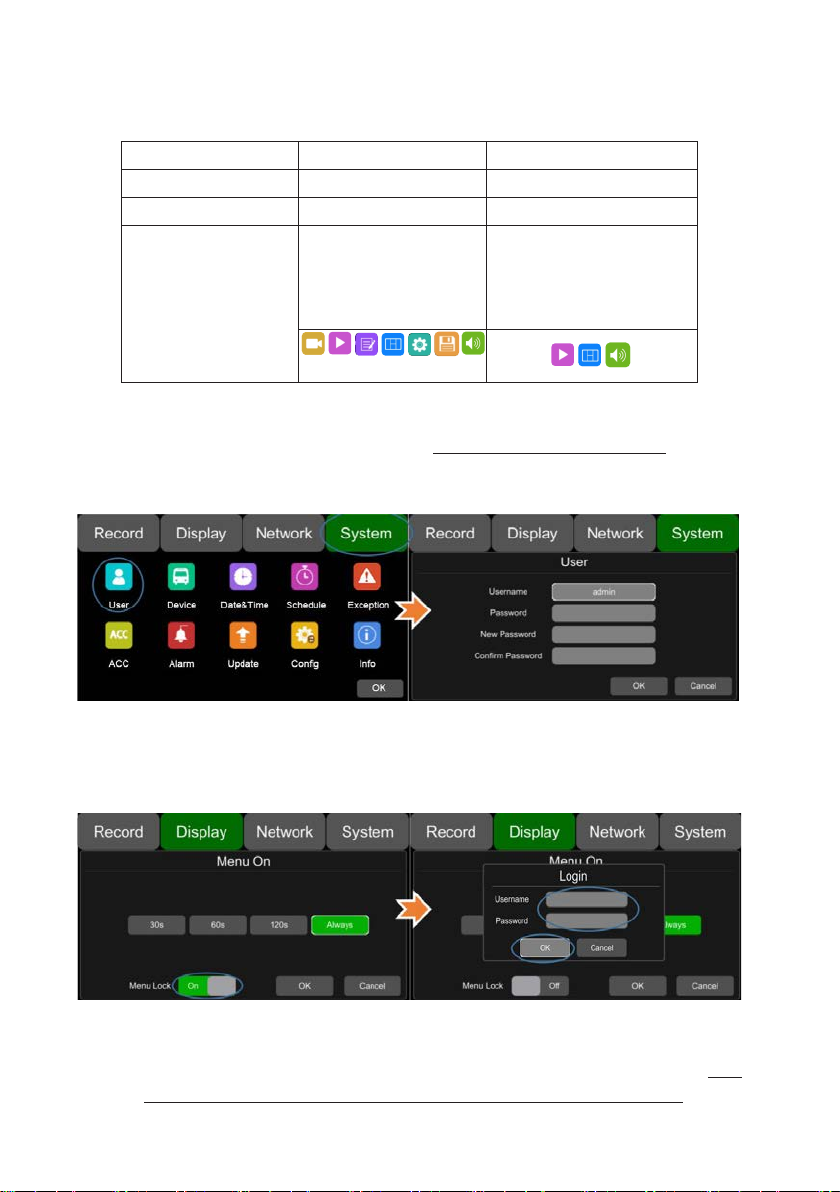
9.6 Menu on
Menu on: Set duration of menu display
47
Page 48

Menu on: Menu on duration can be set to 30s, 60s , 120s an d Always. When it is set to 30s,
60s, 120s, it means that the menu will be hidden if there is no operation in 30s, 60s or
120s after it is open. When it is set to Always, the menu will always be there. Please be
noted that if enter the menu, the recording will stop. In order not to affect the recording, it
is not suggested to set the duration to Alw ays.
Menu lock:
On means permission is required t o ent er t he menu;
Off means permission is not require d t o ent er the menu;
Username admin and password ar e r equired if to change the status of the menu lock.
9.7 Speed
Speed setting:
The data source of overspeed comes from GPS. Speed units are optional:,
Km/h or Mile/h.
Overspeed is the threshold of overspeed, which can be set by user. Speed
refers to the current speed of the vehicle. If the value of Speed exceeds the
value of Overspeed, the over speed alarm recording will be triggered.
The alarm switch is used for setting the overspeed alarm recording ON/OF F. I f
it is ON, the overspeed alarm recording will be triggered when the vehicle is
overspeed. If OFF, the overspee d al arm recording will not be triggered.
48
Page 49

9.8 GPS
GPS: When the GPS antenna is properly installed, latitude, longitude and
speed will be recorded into video files. The menu pr ovides G PS infor mati on of
latitude / longitude, detectabl e sat ellites, accessible satellite etc.
Mode:GPS status. It will be shown as bel ow :
Connected
Disconnect
Locating
49
Page 50

9.9 Mirror
ON: Turn on Mirror function
OFF: Turn off Mirror functi on
10. Network
50
Page 51

10.1 LAN port and server setting
DHCP: Dynamic Host Configuration Protocol. To set it on stands for dynamic IPand
off, for static IP. Static IP must be manually input with IP addr ess, mas k and g atew ay.
MAC address can be automatically assigned or revised.
Enable LAN
step 1: Connect the LAN cable to t he DV R.
step 2: Go to “Network - Cellular” page.
step 3: If DHCP is set to ON, a dynamic IP will be automatically matched. If DHCP is
set to Off, input the IP, mask, gateway and MAC manually.
step 4: Touch OK to exit.
step 5: Go to “Network - Server” page and touch the LAN icon.
51
Page 52

Step 6: Input LAN Server IP and Port. Touch OK to sav e the setting.
10.2 Wi-Fi network setup and server setup
Wi-Fi: Wi-Fi on/off
DHCP: Dynamic Host Configuration Protocol. To set it on stands for dynamic IPand off,
for static IP. Static IP must be manually input with IP address, mask and gateway. MAC
address can be automatically assigned or revised.
SSID: Wi-Fi hot spot list
Ap Internet: If it is ON, the hot spot of this D VR can be found on mobile phones.
52
Page 53

Enable Wi-Fi
Step 1: Wi-Fi hot spot available
Step 2: Connect the Wi-Fi antenna at connector ⑥ of device rear panel
Step 3: Go to Wi-Fi setup int er f ace, set Wi-Fi to ON and open the dynamic IP button.
Step 4: Touch SSID s ub-menu and the Wi-Fi hot spot shows up. Select the hot spot
to connect and input password.
Step 5: Touch OK and quit t he Wi-Fi setup interface.
Step 6: Input Wi-Fi Server IP and Port in “Networ k-Server Setup” page.
Step 7: Wi-Fi network status shows “CONNECT SUCCESS” and server status
shows “Online”.
53
Page 54

10.3 2G/3G/4G control and its network setup
Cellular: Cellular is on, meaning t hat 2G/3G/4G is on.
Network Standard: WCDMA by default.
APN &Access Number: Normally, the user doesn’t need to input user name and
password for APN and Access number. The default setting is available. If it can’t
communicate with the network under the default setting, please consult your local
network carrier.
54
Page 55

Username &Password: Reversed.
OK: Save the settings and quit.
Cancel: Cancel the settings and quit.
Enable 2G/3G/4G
step 1: DVR can search 2G/3G/4G signal locally.
Step 2: Connect the 2G/3G/4G antenna at connect or ⑤of DVR rear panel.
step 3: Open the DVR front housing a nd in ser t the 2G/3G/4G SIM card.
step 4: Go to Cellular setup interface and set Cellular to ON.
step 5: Input the APN and Acce ss Numb er correc t ly. Access Nu mber ca n be s k ipped.
Step 6: Touch “OK” to exit.
step 7: Input 2G/3G/4G Server IP and Port in “Network-Server Setup” page.
step 8: Cellular network status shows “Success” and server status shows “Online”.
55
Page 56

10.4 Network Status
Network Status: Users can check information such as LAN IP address、
MAC address、Wi-Fi network stat us、Wi-Fi IP address、Wi-Fi signal strength、
2G/3G/4G network status、2G/3G/4G signal strength, and Server status.
Additionally, users can verify w het her net work connection is successful or not.
LAN IP: Refers to the static IP set on Network-LAN page or the dynamic IP which is
obtained automatically.
MAC: Refers to the static physical address set on Network-LAN page or dynamic
physical address which is obtained automatically.
Wi-Fi: Wi-Fi on/off status obtained from Network-Wi-Fi page
Wi-Fi RSSI: Wi-Fi signal strength icon
Wi-Fi IP: Static IP obtained from Net w ork-LAN pages or dynamic IP.
56
Page 57

Wi-Fi status: Wi-Fi status will be shown as below:
CONNECT SUCCESS
GETIP ERROR
Cellular : The on/o ff stat us of cellular acquired from Network-c ellular page
Module: Display the Cellular module brand
Wireless RSSI: 2G/3G/4G signal strength icon
Wireless Type: Display the types of 2G/3G/4G module, the parameters and the
corresponding types are show n as f ollows
2G: Receive 2G signal
3G: Receive 3G signal
4G: Receive 4G signal
Wireless Status: Value and corres ponding meanings
1: Module initialization
2: Module exception
3: No SIMcard
4: Cpin locked
5: Signal abnormal
6: Networking failure
SUCCESS: Networking success
...
Server Status: Online / Offline
10.5 Server
The function of server setting is described as above (10.1,10.2,10.3).
57
Page 58

10.6 FTP
Username/Port/Password: Correc t Username / Port / Password of th e FTP server must be
filled in.
FTP: ON/OFF
58
Page 59

Normal File: Two states, OFF and ON
OFF: Upload alarm files only
ON: Upload all files (including Normal Files)
Cellular: Two states, OFF and ON
OFF: Files are not allowed to be uploaded when Cellular is connected to the Internet
ON: Files are allowed t o be uplo ade d wh en Ce llul ar is c onnec te d to th e Internet. To save
network flow data, please select OFF.
Uploading: Display the progress bar of the uploaded file
Filename: Display the file name of the file being uploaded
Status: Display the working status of the FTP function
Successfully uploaded files can be found on the client as below:
59
Page 60

11. System
60
Page 61

11.1 Log in setup
Set user name and password for booting up. The initial password is 123.
11.2 License plate number setup
Input license plate number
61
Page 62

11.3 System time setup
Format Setup:
62
Page 63

Go to “System - Date&Time - Format_Setup” page.
①Time Zone: time zone sett ing.
②Date Format: set the format of date.
③24 Hour: if it is ON, time format will be displayed in 24-hour system. If OFF, in 12-hour
system.
Time Snyc Setup:
63
Page 64

Go to “System - Date&Time - Time Sync_Setup” page.
①GPS: set GPS to ON/OFF
②NTP: set NTP to ON/OFF
③NTP Server: show the URL of the NTP Server
DST Setup:
64
Page 65

Go to “System - Date&Time - DST_Setup” page.
①Enable: Set DCT setting to ON/OFF
②Offset: Adjust the offset after enabling DST
③Mode: Select the mode of DST(setup DST according to week or date)
④Start: Set start time of DST
⑤End: Set end time of DST
11.4 Scheduled Recording
65
Page 66

Enable: Set scheduled recordin g O N/ O FF.
Start: Set start time of scheduled recording.
End: Set end time of scheduled recording.
Week-day: Set scheduled recording by w eekday s. Select the w eekday s t o set pr eset.
Scheduled Recording:
* Support up to four appointed tasks. The recording duration is counted in
minutes.
* Recording time can overlap.
* The start time of scheduled recording must be set ahead of the end time.
11.5 Exception
66
Page 67

Buzzer: Set the buzzer to ON/OFF.
Duration: Set the duration time of the buzzer.
11.6 ACC settings
67
Page 68

Current vol.: Voltage of the work ing DVR
Shutdown vol.: Shutdown voltage function will work after DVR starts working for
1mins. DVR will shut down automaoi.iktically if current v oltage is lower than shut down
voltage, and it will reboot only when the volt age is above the value.
ACC Duration: DVR will continue recording for a few seconds after ACC is
disconnected. ACC delay time can be set to be 5s, 60s, 30min or 60min.
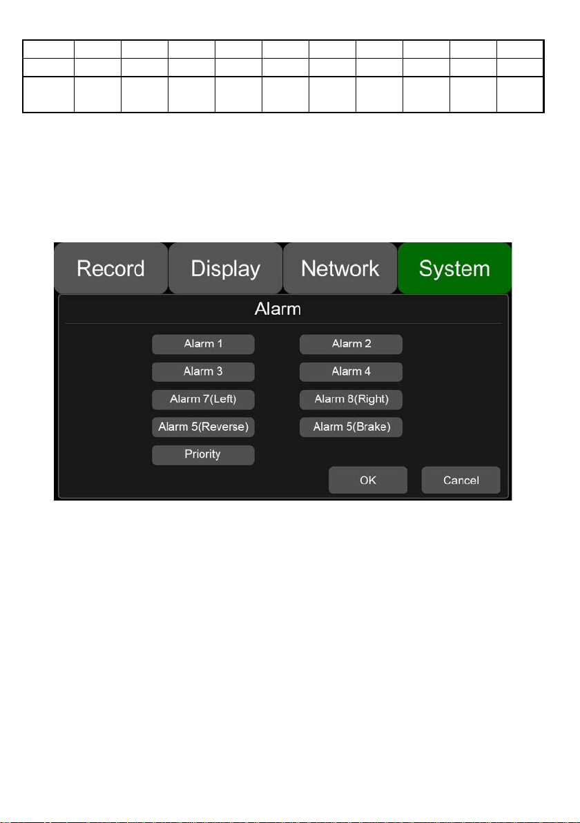
11.7 Alarm information setting
Alarm1~Alarm4: Customized alarm recording
Reverse: Reversing alarm recording. Parking line cursor will display when reverse
alarm is triggered.
Brake: Brake alarm recording. Brake sign will display w hen brake alarm is triggered.
Left: Turning-left al arm recording. Turn-left cursor will display when turn left alarm is
triggered.
Right: Turning-right alarm recording. Turn-right cursor will display when turn right
alarm is triggered.
68
Page 69

Priority: Set prioriti es for Alarm1~Alarm4, Reverse, Brake, Left, and Right.
When different types of alarm are triggered at the same time, alarms with the highest
priority will work first.
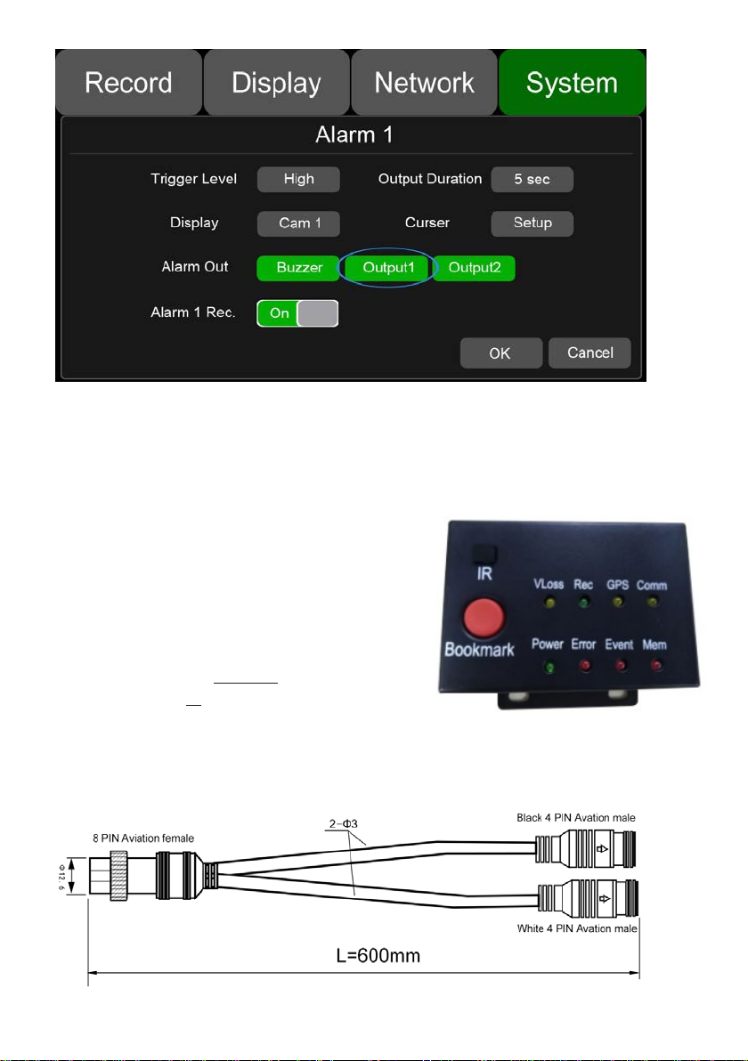
Trigger Level: There are 3 options of Trigger Level. The options “Low” and ” High”
are used for turning on alarm function. “Low” is generally used for debugging while
“High” will be selected to turn on alarm function for on-road use. “Off” means turning
off alarm trigger function.
Duration: Duration of alarm video recor ding
Alarm Out-Buzzer: Set the Buzzer ON, then it would beep for 5 seconds when
alarming.
Alarm Out-Output1: Set it ON, then 12V level output would come from the alarm
wire of Output 1
Alarm Out-Output2: Set it ON, then 12V level output would come from the alarm
wire of Output 2
Display: A full screen of one channel will display when this channel is triggered.
Curser: See the picture below.
69
Page 70

①Camera name of the alarm-triggered channel.
②Press this button to turn on/off curser .
③Line selecting: There are five lines to be selected, Line U(up), Line D(down), Line
L(left), Line R(right) and ALL. The button is green if selected. You can use remote
control to operate.
④There are four directions to adjust the shape of the cursor, Up,Down, Left and
Right.
If Line U(the green one) or Line D(the red one) is selected, the selected line can be
moved totally with these direction but t ons.
If Line L or Line R is selected, the top po int of the select ed line can b e moved to le ft or
right with Direction Up and Direction Down, and the bottom point of the selected line
can be moved to left or right with Direct ion Left and Direction Right.
⑤Lines of curser. The selected on e w il l b e t hickened for three times. The two lines in
the middle will not be processed.
⑥Touch OK to save the settings and exit. Cancel to exit without saving any settings.
Priority: See the picture below.
70
Page 71

: Press it, then the priority value of the selected alarm will be added by 1. The
bigger the value is, the lower t he pr iorit y will be.
: Press it, then the priority value of the selected alarm will be reduced by 1. The
smaller the value is, the higher t he pr i or it y will be.
Alarms with higher priority will be triggered first.
1 is the highest priority, and 8 is the lowest.
If two alarms A and B are triggered at the same time, and A’s priority is higher
than B’s, then A will record first. After A finishes the recording, if B is still being
triggered, B will then record. However, if B is no longer being triggered now, it
will not record.
If alarm B is triggered and at the process of recording, however, alarm A, whose
priority is higher than B, is triggered then, B will not stop recording.
11.8 Update
For single device
Step 1: Copy the folder to USB disk or SD card root directory and insert the USB disk
or SD card into DVR.
Step 2: Power off the DVR and reboot it, then it will upgrade automatically. Or in the
menu Menu -> System -> Update, touch OK to confirm to upgrade. Both methods can
start the upgrade process.
71
Page 72

Step 3: When “Update success!” is shown on the DVR monitor, the DVR will reboot
automatically.
72
Page 73

Step 4: After rebooting, please check if the version is the same as the one you copy
into “upgrade” folder. Please go to M enu -> System -> Info to check it.
For batch upgrade
As the upgrade package will be deleted after the upgrade process is done on
device, so if you need to upgrade more t han one device, please carry out as follows:
Step 1: Rename the package “dvxxx_upgrade_201xxxxxxxxx” to
“dvxxx_upgrade_never_rename”( " xxx" in the "dvxxx_upgrade_never_rena me" is the
corresponding product model number)
Step 2: Copy the package to the root directory of USB disk or SD card , and insert it
to DVR.
Step 3: Power off the DVR and reboot it, then it will upgrade automatically. Or in the
menu Menu -> System -> Update, touch OK to confirm to upgrade. Both methods can
start the upgrade process.
73
Page 74

Step 4: After When “Update success!” shows, unplug the USB disk or SD card with
upgrade package, then DVR will reboot automatically.
74
Page 75

Note: If using “dvxxx_upgrade_never_rename” package to upgrade, we must
unplug the USB disk or SD card when “ update success!” is shown on the screen, or
else the DVR will go into infinite loop of upgrade and will not boot up.
SOLUTION: Unplug the USB disk or SD card with upgrade package, and then DVR
will stop the upgrade process and boot up successfully.
Remote upgrade
Step 1:DVR connects to server.
Step 2:Open the Windows client and log in.
Step 3:Find the license number of the target DVR device in the device list of the
client, right click and select “Update” to open the Batch Upgrades interface. If you
need to upgrade more than one device, you can click the Add button to select other
devices. The selected ones will be disp layed on the dev ice list to upgrade. I f you want
to remove devices from the list, please select them and click the Del button.
Step 4 :Select the device to upgrade, and then click the Browser button to select the
upgrade package “dvxxx_upgrade_201xxxxxxxxx”.
Note: For remote upgrade the package can’t be named as
“dvxxx_upgrade_never_rename”.("xxx" in the "dvxxx_upgrade_never_rename" is the
corresponding product model number)
Step 5: Click the Start button to upload the upgrade package. When uploading is
finished, the device will start to upgrade automatically. If it is failed to upload, the
reason of failure will be displayed in t he R emark column in the list.
75
Page 76

11.9 Configuration
Configuration Import: Import t he configuration in formation fr om USB memory
flash devices.
Configuration Export: Export Log t o USB memory flash devices.
Factory Default: Press RESET to restore factory settings.
76
Page 77

11.10 System Info
System Info:Software version number.
77
Page 78

12. FAQ
1) The system can’t start up?
Check power connection. Please follow the steps below to check the power
connection:
1. Check the input power: if the power wire is connected correctly, if the ground
wire is connected to the battery, and if the fuse on the power wire is in good
condition.
2. Check if the voltage of the ACC signal wire is higher than 6 V.
3. Check if he input voltage of the dev ice is hig her than the shutdow n voltage s et on
the screen of HD DVR.
2) The HD DVR restarts uninterruptedly?
Please follow the steps below to check it :
1. Check if the supply voltage of DVR is insufficient. If it is lower than the start-up
voltage of the device, the device would restart repeatedly.
2. Restart HD DVR to see if it can work proper ly this time.
3) Unable to recognize disks?
1. Check if the disk itself is in good condition and make sure that it is installed and
of fine contact.
2. The disk has been formatted by DVR.
3. Restart DVR to see if it can work properly t his t ime.
4) Unable to recognize cameras?
1. Make sure the camera is intact and the co nnection is correct.
2. Refit all wires (e.g,DB44 wire & extended wires) between cameras and t he
device .
3. Restart DVR to see if it can work properly this time.
5) GPS anomaly?
Check if the GPS antenna is properly installed.
78
Page 79

13. APPENDIX
APPENDIXⅠ:Abbreviation & Description
Rec. Record SD Secure Digital Memory Card
G-sensor Accelerometer sensor USB Universal Serial Bus
GPS Global Positioning System DB44
Wi-Fi WIreless-FIdelity DB26
Cam Camera ALM Alarm
AVI Audio Video Interleaved VLOSS Video Loss
OSD On-Screen Display COMM Communication
APN Access Point Name ERR Error
DHCP
SSID Service Set Identifier MMSHOW
IP Internet Protocol FTP File Transfer Protocol
MAC Media Address Control DVR Digital Video Recorder
Dynamic Host Configuration
MEM Memory
Protocol
44PIN connector, A/V Input,
Output.IO/ALARM Output
26PIN connector, Alarm
Input/RS232/RS485
Media Player
RSSI
SSD Solid State Drive SYS System
LED Light Emitting Diode
Received Signal Strength
IR Infrared Radiation
Indication
79
Page 80

APPENDIXⅡ:Accessories
NULL
80
Page 81

Test Read
Test Write
MTFDDAK960
Typical
(MB/s)
Typical
(MB/s)
Capacity
Interface
(MB/s)
(MB/s)
Standard
Test Read/Write,
Update software,
SDHC
Standard
Test Read/Write,
Update software,
SDHC
Standard
Test Read/Write,
software,
APPENDIXⅢ:Compatibility Storage List
SATA 3.0 SSD
Brand
Name
Model Name
SIZE
(inch)
Flash
Capacity Interface
Type
Speed
(MB/s)
Toshiba HDTS812 2.5 TLC 120G SATA3 98.0 119.7
Micron
TCC
2.5 TLC 960G SATA3 67.4 73.8
Samsung MZ-750120 2.5 TLC 120G SATA3 94.6 100.9
Samsung MZ-75E500 2.5 TLC 500G SATA3 72.5 124.2
Samsung
MZ-7KE1T0B
W
2.5 MLC 1T SATA3 64.9 77.4
SanDisk SDSSDA-120G 2.5 SLC 120G SATA3 99.6 70.5
Toshiba
Toshiba
THNSNJ256G
CSU
THNSNJ512G
CSU
2.5 MLC 256G SATA3 -- --
2.5 MLC 512G SATA3 -- --
Toshiba Q300PRO 2.5 MLC 1T SATA3 -- --
SD Card
Test
Brand
Name
Model Name
Card
Type
Read
Speed
Write
Speed
(GB)
Hot
Plug
Read
Speed
Test
Write
Speed
Speed
(MB/s)
Remarks
Lexar
SanDisk
SanDisk
Lexar 128G
633X
SDXXG-032G-Z
N4IN
SDSDUNC-128
G-ZN6IN
SDXC
UHS-I
10
10
95 45 128
95 90 32
80 75
128
81
OK 7.1 9.4
SD
OK 9.2 12.6
SD
OK 7.4 11.5
SD
HotPlug
HotPlug
Update
HotPlug
Page 82

TOSHIBA
Standard
Test Read/Write,
Update software,
Standard
Test Read/Write,
Update software,
Standard
Test Read/Write,
Update software,
Transcend 64GB
Standard
Test Read/Write,
Update software,
Transcend 32GB
Standard
Test Read/Write,
Update software,
Transcend 64GB
Standard
Test Read/Write,
Update software,
Standard
Test Read/Write,
Update software,
THN-N302R032
0C4
SDHC
10
90 40 32
SD
OK
6.5 10.1
HotPlug
TOSHIBA
TOSHIBA
Transcend
Transcend
Transcend
Transcend
THN-N302R064
0C4
THN-N302R012
80C4
UHS-I U3
UHS-I 600X SD
UHS-I 600X SD
Transcend
128GB UHS-I U3
SDHC
10
SDHC
10
SDXC
UHS-I
SDHC
10
SDHC
10
SDHC
10
90 40 64
90 40 128
95 60 64
90 40 32
90 40 64
95 60 128
OK
SD
OK 7.2 9.3
SD
OK 7.3 10.6
SD
OK 6.9 7.5
SD
OK 6.0 6.3
SD
OK 7.1 9.0
SD
7.8 6.2
HotPlug
HotPlug
HotPlug
HotPlug
HotPlug
HotPlug
82
Page 83

83
Page 84

DV426/DV426-4G
84
 Loading...