

Axis D201-S XPT Q6055 Explosion-Protected PTZ Network Camera Manufacturer specific manual
SPECTRUM D201-(1)-Q6055-E-BD Series
D201-A-Q6055-E-BD
D201-S-Q6055-E-BD
Explosion Proof Network Camera
Installation Manual
D201-1-Q6055 REV 4 105607312018 D SERIES
INSTALLATION MANUAL REV-1
1

This pageintentionallyleftblank
INSTALLATION MANUAL REV-1
2D201-1-Q6055 REV 4 105607312018 D SERIES
Information in this document is subject to change without notice. All terms
Aug 30, 2018
Oct 10, 2018
July 15, 2019
Feb 5, 2020
Feb 18, 2020
mentioned in this manual that are known to be trademarks have been
appropriately capitalized. Spectrum Camera Solutions LLC acknowledges
all trademark(s) and the rights of the trademark(s) owned by the company
referred to herein.
Release Date:08/30/2018
Document Name D201-(1)-Q6055-E-BD
© Copyright 2019 by Spectrum Camera Solutions LLC All rights
reserved
Revision Record
Rev. Description Date
0 Initial Release
1 Updated
2 EU
3 Format adjust
4 coc
D201-1-Q6055 REV 4 105607312018 D SERIES
INSTALLATION MANUAL REV-1
3

Copyright Notice:
This document contains information proprietary to Spectrum Camera Solutions LLC
with all rights reserved worldwide. Any reproduction or disclosure of this publication,
or any part thereof, to persons other than Spectrum Camera Solutions, Inc.
personnel or customers is strictly prohibited, except by written permission of
Spectrum Camera Solutions, Inc. Unauthorized use, disclosure, reproduction, or
translation of this publication will result in Spectrum Camera Solutions, Inc.
exercising maximum possible legal action against all persons and / or organizations
involved.
Disclaimer:
Spectrum Camera Solutions LLC makes no representations or warranties with
respect to the contents hereof. Further, Spectrum Camera Solutions LLC reserves
the right to revise this publication and to make changes in the content hereof, without
obligation to notify any person or organization of such revision or changes.
Patent Notice:
Manufactured under United States US Patent 9917428 & US Patent D858611
Trademark Information:
Spectrum Camera Solutions LLC and its logo(s) are trademark(s) of Spectrum
Camera Solutions LLC.
D201-1-Q6055 REV 4 105607312018 D SERIES
INSTALLATION MANUAL REV-1
4
Table of Contents
Legal Notices and Revision History Inside front cover
DESCRIPTION 6
MODEL MATRIX 7
LABELS 8
STANDARDS AND CERTIFICATIONS 9
DOCUMENT SYMBOLS 10
HOW TO USE THIS MANUAL 11
Page
GENERAL SAFETY AND OPERATING INFORMATION 12
SPECIFICATIONS 15
UNBOXING 17
HARDWARE BOM 18
WIRING ENTRIES 19
INSTALLATION 20
DIMENTIONAL GENERAL ASSEMBLY 25
DISMANTLING & MAINTENANCE 26
MOUNTING OPTIONS 28
D201-1-Q6055 REV 4 105607312018 D SERIES
INSTALLATION MANUAL REV-1
5

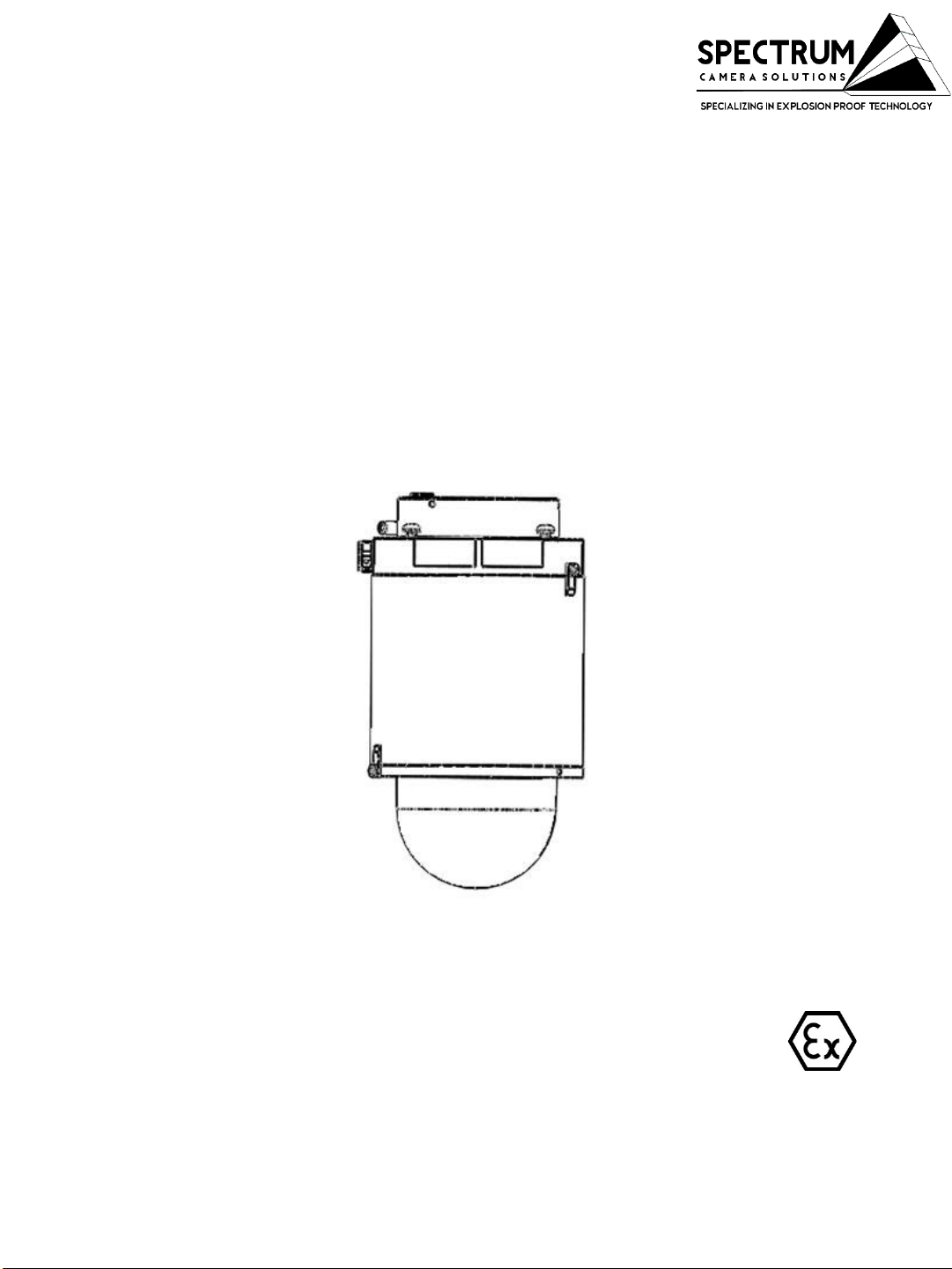
DESCRIPTION
The “D” Series includes a full range of Stainless Steel or Anodized Aluminum camera stations
specifically designed for Hazardous Area Applications.
Spectrum’s D Series is the first Class I II III Division 1 rated dome style explosion proof
housings and utilizes the most robust and advanced camera technologies available. The D
Series was designed with the integrator in mind and offers features not available in competing
EX camera systems available in the market. The solution is Patented with features including a
uniform constructed enclosure consisting of an integrated junction box milled directly to the
camera housing. This eliminates the need for extra equipment, reduces installation time,
reduces labor expenses, and increases safety by lessening the potential for mismatched
hazardous rated components. Additionally, the D Series are constructed with a proprietary
explosion resistant polymer blend offering maximum clarity and enhance optical performance.
To enhance optical performance, the explosion proof lens is equipped with our Virtual Wiper
Nano Technology. The series are available in anodized aluminum or 316L Stainless steel
ensuring protection against rain, dust and corrosion within a wide temperature range between 20°C to 55°C. This feature ensures operation under extreme weather conditions and hazardous
environments. It is suitable for monitoring wide open indoor/outdoor spaces such as refineries,
wellheads, pipelines, offshore installations, remote and harsh locations where high-level
reliability and precision are always required.
D201-1-Q6055 REV 4 105607312018 D SERIES
INSTALLATION MANUAL REV-1
6

Option A- Model Matrix- D100-D500*
CODE “XX”
01
D(N)(XX)-(1)-(CCCCCC)-BD
N=(1) HOUSING LENGTH=3.32 in
N=(2) HOUSING LENGTH=7.75 in
N=(3) HOUSING LENGTH=4.5 in
N=(4) HOUSING LENGTH=5 in
N=(5) HOUSING LENGTH= 5.5 in
XX= Internal Equipment Manufacturer Code**
1= (A) Aluminum Housing with SS 316L Dome Ring
1= (S) Stainless Steel 316L Housing
C= Internal Equipment Part Number from Manufacturer***
BD= Optional Breather drain model****
*Internal components and D Series must be approved by Spectrum
**Internal Equipment Manufacturer Code below
***Must be approved and verified by Spectrum
****Models supplied with Breather Drains will have IP66 ingress protection level
Manufacture
AXIS COMMUNICATIONS
D201-1-Q6055 REV 4 105607312018 D SERIES
INSTALLATION MANUAL REV-1
7
Labels Option A
BREATHER DRAIN MODEL
BREATHER DRAIN MODEL
INSTALLATION MANUAL REV-1
8D201-1-Q6055 REV 4 105607312018 D SERIES
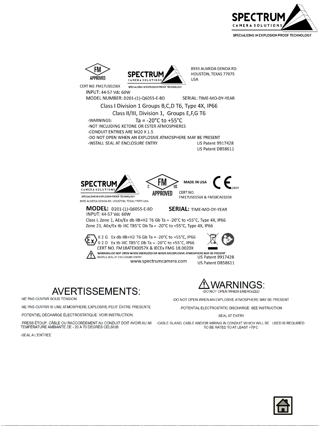
STANDARDS & CERTIFICATIONS
STANDARDS-
The equipment is manufactured in accordance with the IECEX scheme, the ATEX Directive 94/9CE and with the
following standards :
IEC 60079-0:2011
IEC 60079-1:2014
IEC 60079-31:2013
IEC 60529:2013
EN 60079-0:2012 + A11:2013
EN 60079-1:2014
EN 60079-31:2014
EN 60529:1991 + A1:2000 + A2:2013
ANSI/ISA 60079-0:2013
ANSI/UL 60079-1:2015
ANSI/ISA 60079-31:2015
ANSI/IEC 60529:2004
CAN/CSA-C22.2 No. 60079-0:2015
CAN/CSA-C22.2 No. 60079-1:2016
CAN/CSA-C22.2 No. 60079-31:2015
CAN/CSA-C22.2 No. 60529:2016
Specific Conditions of Use:
-The flameproof joints of the equipment are not intended to be repaired. Consult the manufacturer if dimensional
information on the flameproof joints is necessary.
-Follow the manufacturer’s instructions to reduce the potential of an electrostatic charging hazard on the surface
of the equipment in Group II and III environments.
-The equipment meets the requirements according to the low level risk of mechanical danger. Therefore, the
equipment shall be located and installed such that the risk of impact or other mechanical damage is reduced or
avoided.
NOTE: Use a clean cloth dampened with pure water for cleaning.
CERTIFICATIONS-
CERT NO. FM17US0156X & FM18CA0103X
Class I Division 1 Groups B,C,D T6, Ta = -20°C to +55°CType 4X, IP66/67
Class II/III, Division 1, Groups E,F,G T6 Type 4X, IP66/67 Ta = -20°C to +55°C
Class I, Zone 1, AEx/Ex db IIB+H2 T6 Gb Ta = -20°C to +55°C, Type 4X, IP66/67
Zone 21, AEx/Ex tb IIIC T85°C Db Ta = -20°C to +55°C, Type 4X, IP66/67
CERT NO. FM18ATEX0057X & IECEx FMG 18.0020X
II 2 G Ex db IIB+H2 T6 Gb Ta = -20°C to +55°C, IP66/67
II 2 D Ex tb IIIC T85°C Db Ta = -20°C to +55°C, IP66/67
INSTALLATION MANUAL REV-1
9D201-1-Q6055 REV 4 105607312018 D SERIES
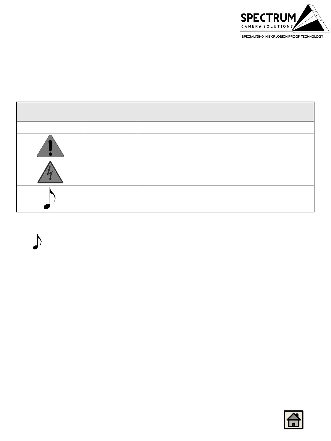
DOCUMENT SYMBOLS
The following symbols are used throughout this manual to alert users to potential
hazards or important information. Failure to heed the warnings and cautions listed
herein can lead to injury and equipment damage.
Symbol Label Description
WARNING:
CAUTION:
Consists of conditions, practices, or procedures that
must be observed to prevent personal injury and/or
equipment damage.
Risk of electric shock or high temperature parts may
result in injury if proper precautions are not taken.
NOTE:
Emphasizes important or essential information.
Locating Information:
NOTE: In the interest of completeness, manuals and drawings included with the
system may provide information pertaining to options not included with your
equipment. Information in application notes supersedes general information in
these documents. Information can be in this manual using any of the following aids.
INSTALLATION MANUAL REV-1
10D201-1-Q6055 REV 4 105607312018 D SERIES
How to use this Manual
General Manual:
This manual is intended to be used in conjunction with installed equipment
manual from internal equipment manufacturer.
Note: In the event of a conflict between the requirements of this general
installation manual and the internal equipment manual, the safety and
installation procedures described in this manual shall take precedence.
Safety Considerations:
This information that must be read and understood by all persons installing,
using, or maintaining this equipment. This manual is designed to aid
personnel in the correct and safe installation, operation, and maintenance of
the systems described. Personnel must consider all actions and procedures
for potential hazards or conditions that may not have been anticipated in the
written procedures. If a procedure cannot be performed safely, it must not be
performed until appropriate actions can be taken to ensure the safety of
equipment and personnel. The procedures in this manual are not designed to
replace or supersede required or common-sense safety practices. All safety
warnings listed in any documents applicable to equipment and parts used in
or with the system described in this manual must be read and heeded before
commencing work on any part of the system.
NOTE: Refer to all ATEX, CSA, IECEx, NEC, NFPA and FM certificates
for any Special Conditions of Use. If the sign “X” is placed after the
certificate number, it indicates that the equipment or protective
system is subject to special conditions for safe use specified in the
schedule of the certificate.
NOTE: Review all material and safety information in this manual and
install in accordance with this document and all other applicable
ATEX, CSA, IECEx, NEC, NFPA70 Installation Methods and FM and
National standards.
Warning- Failure to follow appropriate safety procedures or
appropriate use of the equipment described in this manual can lead to
injury of personnel or equipment damage.
WARNING – EXPLOSION HAZARD – Do not open equipment
unless power has been removed or the area is known to be nonhazardous.
INSTALLATION MANUAL REV-1
11D201-1-Q6055 REV 4 105607312018 D SERIES
 Loading...