

Page 1

USER MANUAL
AXIS Camera Station
Page 2

About This Document
This manual is intended for administrators and users of AXIS Camera
Station and is applicable for software release 3.50 and later. It covers
configuration of AXIS Camera Station Server and AXI S Camera Station
Client as well as instructions for using and managing AXIS Camera
Station on your network. Later versions of this docum e nt will be posted
on Axis web site, as required. See also the product’s help pages.
Intellectual Property Rights
Axis AB has intellectual property rights relating to technology embodied
in the product described in this document. In particular, and without
limitation, these intellectual property rights may include one or more
of the patents listed at http://www.axis.com/patent.htm and one or
more additional patents or pending patent applications in the US and
other countries.
Legal considerations
Video and audio surveillance can be regulated by laws that vary from
country to country. Check the laws in your local region before using
this product for surveillance purposes.
Liability
Every care has been taken in the preparation of this manual. Please
inform your local Axis office of any inaccuracies or omissions. Axis
Communications AB cannot be held responsible for any technical or
typographical errors and reserves the right to make changes to the
product and manuals without prior notice. Axis Communications A B
makes no warranty of any kind with regard to the material contained
within this document, including, but not limited to, the implied
warranties of merchantability and fitness for a particular purpose. Axis
Communications AB shall not be liable nor responsible for incidental or
consequential damages in connection with the furnishing, performance
or use of this material.
Trademark Acknowledgments
Microsoft, Windows, Windows Vista, WWW, Internet Explorer, DirectX,
Intel, Intel Core, Pentium and Xeon are reg istered trademarks of the
respective holders.
Support
Should you require any technical assistance, please contact your Axis
reseller. If your questions cannot be answered immediately, your
reseller will forward your queries through the appropriate channels to
ensure a rapid response. If you are connected to the Internet, you can:
• download user documentation and software updates
• find answers to resolved problems in the FAQ database. Search
by product, category, or phrase
• report problems to Axis support staff by logging in to your private
support area
• chat with Axis support staff (selected countries only)
• visit Axis Support at www.axis.com/techsup/
Page 3

AXIS Camera Station
Table of Contents
SystemRequirements ........................................ 4
Overview .................................................. 5
AXISCameraStationServer ....................................... 5
AXISCameraStationClient ....................................... 5
MultipleServers ................................................ 6
Workspaces ................................................ 8
LiveView ...................................................... 8
Recordings ..................................................... 12
CameraManagement ............................................ 16
Logs .......................................................... 18
Configuration .................................................. 19
AlarmsandTasksTabs ............................................ 20
Licenses ................................................... 22
RegisteringLicenses ............................................. 22
LicenseTypes ................................................... 22
SupportLicense ................................................. 22
LicenseTransition ............................................... 23
Decoders ...................................................... 23
Howto... .................................................. 24
AddCamerasandVideoEncoders .................................. 24
Add Auxiliary Devices . . . . . . . . . . . . . . . . . . . . . . . . . . . . . . . . . . . . . . . . . . . . 26
SetUpRecording ................................................ 26
SetUpRecordingStorage ......................................... 30
CreateViews ................................................... 31
AddaPTZPresetPosition ......................................... 36
EnableAudioinLiveView ......................................... 36
EnableAudioinRecordings ....................................... 36
Configure a Media Profile ......................................... 37
Override Media ProfilesinLiveView ................................ 37
UseAudiofromanAuxiliaryDevice ................................. 38
AddInputsandOutputs .......................................... 38
SetUpSchedules ................................................ 39
Send E-Mail NotificationonSystemAlarm ........................... 40
ExportRecordings ............................................... 40
UpgradeFirmware ............................................... 40
AssignIPAddresses .............................................. 42
RegisteraMyAxisAccount ........................................ 42
Event ConfigurationWizard ................................... 43
CreateaRule ................................................... 43
AddTriggers .................................................... 44
AddActions .................................................... 45
SetaSchedule .................................................. 47
RuleDetails .................................................... 47
Network
NATandFirewall ................................................ 49
ServerProxySettings ............................................ 49
ClientProxySettings ............................................. 50
Server Port Configuration ......................................... 51
UserPermissions ................................................ 51
InputDevices .............................................. 53
Hotkeys ....................................................... 53
AXIS T8311 Video Surveillance Joystick . . . . . . . . . . . . . . . . . . . . . . . . . . . . . . 53
AXIS T8312 Video Surveillance Keypad . . . . . . . . . . . . . . . . . . . . . . . . . . . . . . 54
AXIS T8313 Video Surveillance Jog Dial . . . . . . . . . . . . . . . . . . . . . . . . . . . . . . 56
AXIS 295 Video Surveillance Joystick . . . . . . . . . . . . . . . . . . . . . . . . . . . . . . . . 56
AXISCameraStationServiceControl ........................... 58
ModifyServerSettings ........................................... 58
AXISCameraStationServiceAdministration ..................... 61
SupportedOperations ............................................ 61
Troubleshooting ............................................ 63
Contact Customer Support . . . . . . . . . . . . . . . . . . . . . . . . . . . . . . . . . . . . . . . . 67
and Security Configuration ............................
49
3
Page 4

AXIS Camera Station
System Requirements
System Requirements
For best performance and stability these minimum requirements must be met.
AXIS Camera Station Client
• Windows® 7 P rofessional, Windows Vista® Business, Windows® XP Professional
• CPU: Intel® Pentium® 4, 2 GHz (Intel® Core™ i7 recommended for larger systems)
• RAM: 1 GB (4 GB recommended for larger systems)
• Hard drive: 1 GB free memory
• Screen: 1024 x 768
• Graphics card with DirectX® 9.0c; Onboard video memory of 256 MB
• Microsoft® .NET runtime environment (included in installation package)
Note
Use the latest graphics card driver.
AXIS Camera Station Server
• Windows® 7 Professional, Windows Vista® Business, Windows® XP Professional, Windows® Server 2008 R2,
Windows® Server 2008, Windows® Server 2003 (64–bit versions recommended for larger systems)
• CPU:Intel®Pentium®4,2GHz(Intel®Xeon®recommendedforlargersystems)
• RAM: 1 GB (8 GB recommended for larger systems)
• Microsoft® .NET runtime environment (included in installati
Network
• 100 Megabit n etwork (Gigabit network recomme
Hard disk configuration
• At 30 fps in VGA with comp
Note
Make sure to always have the latest service packs and video drivers installed on your system.
ression30upto15camerasperharddisk
ndedforlargersystems)
on package)
4
Page 5

AXIS Camera Station
Overview
Overview
AXIS Camera Station is a complete monitoring and recording system for Axis network cameras and video encoders. AXIS Camera
Station is comprised of
• AXIS Camera Station Server — handles all com munication with the cameras and video encoders and recordings. Each
server can communicate with up to 100 cameras/encoders.
• AXIS Camera Station Client — graphical interface enabling remote viewing and control from anywhere on the Internet or
corporate network
Several Clients can be connected to the same Server, and each C lient can be connected to several Servers. See Multiple Servers, on
page 6 .
AXIS Camera Station One has all the basic features of A X IS Camera Station for one camera/video channel.
Installation scenario. AXIS Camera Station Server, installed on a dedicated computer, handles the communication with cameras both
inside and outside the local (corporate) network. The cameras are monitored and controlled from two AXIS Camera Station Clients —
one on the local network and one connected via the Internet.
AXIS Camera Station Server
AXIS Camera Station Server handles all communication with the c ameras that are included in the system. It also han dle s recordings,
events and user management in the system. Once AXIS C amera Station Server has been installed on your computer, the Service
Control allows you to start and stop the server as well as modify server settings if needed. If AXIS Camera Station Server and any
cameras in the system are separated by a proxy server, you may need to open the Service Control to manually enter the appropriate
proxy settings. See AXIS Camera Station Service Control Help for more information.
An icon in the system taskbar shows if the service has stopped
the icon to open
Service Administration, on page 61.
AXIS Camera Station Service Control, see A XIS Camera Station Service Control, on page 58 and AXIS Camera Station
, or is running . To modify server settings you can double-click
AXIS Camera Station Client
The user interface is developed with a focus on ease-of-use and intuitive handling with navigation too ls providing quick access
to cameras and recordings in the system. AXIS Camera Station is divided into six areas called workspaces: Start page, Live View,
Recordings, Camera Management, Logs and Configuration.
5
Page 6

AXIS Camera Station
Overview
The first time the application is started, AXIS Camera Station automatically finds and adds the cameras and video encoders that are
on your network. If there are more cameras than you have a license for, the Camera Search dialog will pop up allowing you to select
which devices to add, s ee Add Cameras and Video Encoders, on page 24.
Multiple Servers
AXIS Camera Station Client can be connected to multiple AXIS Camera Station Servers. Select N
to connect to a new server. Servers can also be organized in server lists, see Server Lists,below.
Recent Connections in the File menu displays recently used servers. Select a server to connect to or disconnect from that server.
The Selected server drop-down list is available in the client toolbar and in several dialogs when connected to more than one server.
When this list is shown, the client displays the cameras, recordings, events, logs, etc on the server selected in the list. Select
another server to access devices and recordings on th
at server.
ew Connection from the File menu
6
Page 7

AXIS Camera Station
Overview
The Camera Management workspace and the Alarms and Tasks tabs at the bottom of the client’s main window, see Alarms and Tasks
Tabs, on page 20, display devices and alarms from all connected servers. In the Live View workspace, you can create split views
with cameras from different se rvers.
Server Lists
Server lists are useful when working with a large number of servers, and when using the s ame servers for clients on different
computers.
To create and edit server lists, go to File > Switch to Servers > Server Lists. A server can belong to more than one list.
Once created, you can connect to all servers in a list by selecting the list from the Multiple servers drop-down list in the Connect to
AXIS Camera Station dialog displayed when starting the client. To switch between server lists, open the File menu, point to Switch to
Servers and select the server list to connect to.
Server lists can be exported and imported into other AXIS Camera Station Clients. To export/import a server list, open the File menu,
select Import/Export and then Export Server Lists or Import Server Lists.
7
Page 8

AXIS Camera Station
Workspaces
Workspaces
AXIS Camera Station i s divided into workspaces:
The Start page gives an overview of AXIS Came ra Station, highlights new features and contains contact information for
technical support. When disconnected from the server, this is the only workspace available.
The Live View workspace provides a single interface to organize, monitor and control Axis network cameras and video
encoders.
The Recordings workspace handles recording se arch, playback, export and management.
The Camera Management workspace provides tools for efficient administration and maintenance of connected devices,
such as firmware upgrade, assigning IP addresses, setting passwords and date and time settings.
The Logs workspace contains alarm, event and audit logs.
The Configuration workspace is a collection of all the important links for configuring AXIS Camera Station.
The workspaces are easily acce ssed by clicking on the naviga tion buttons in the toolbar or by selecting the workspace from the View
menu.
Devices and Cameras
In AXIS Camera Station, the terms device and camera are used as follows:
Device A network product that has its own IP address. A device can be:
•anetworkcamera
• a video encoder (video server)
• an auxilia ry device
Camera
Auxiliary device
Example
A 4–port video encoder is one device with four cameras.
Note
Some video encoders have one IP address for each video port. In this case, each video port is treated as one device with
one camera.
A video source, that is,
•anetworkcamera
• a video port (with a connected analog camera) on a video encoder
Each camera requires one AXIS Camera Station license.
A network device without video ports, for example a
without an additional AXIS Camera Station license.
n I/O audio module. Auxiliary devices can be added
Live View
The Live View workspace provides a single interface to organize and monitor Axis network cameras and video encoders on your
network. You can, for example, set up view groups, record, and control a udio and pan/tilt/zoom (PTZ) functionality.
8
Page 9

AXIS Camera Station
Workspaces
Live View workspace
1
Menu
2
Server selection list
3
Toolbar
4
Recording indicator
5
Workspace buttons
6
View groups
7
Audio, PTZ Control, Foc us Control, Image Enhancement and Ca mera Status
8
Alarms and Tasks tabs
9
Alarms a nd Tasks toolbar
Views
There are five view types in AXIS Camera Station:
Split View Displays up to 25 views in one window. One frame can be set as a hotspot that automatically loads the view from
another frame when clicking in that frame.
Sequence Switches automatically between selected views, with variable dwell times.
Camera View Live video from one camera or video encoder. Camera views c an be added to split views, sequences and map s.
Map Imported image, for example a floor plan, on which camera views, split views, sequences, web pages and other
Web Page
maps can be placed. Providing a visual overvie w, maps make it easy to quickly locate and acces s individual
cameras in t
External web application integrated into AXIS Camera Station. Web pages can be shown in a split view or a
sequence together with live video.
he network video insta llation.
For instructions on how to add split views, sequences and maps, see Create Views, on page 31.
9
Page 10

AXIS Camera Station
Workspaces
Views can be used in event actions, see Event Configuration Wizard, on page 43.
View Groups
Views can be organized into view groups. A view group contains automatic or user-defined views. The following view groups are
available in the pane in the left hand sid e of the Live View workspace:
• Auto Views — Automatically created split views for up to 25 cameras.
• My Views — User-created views. These views are available to the current user only.
• Shared Views — Views created by an administrator or operator that are accessible by all users.
• Camera Views — All cameras and video encoders that have been added to AXIS Camera Station.
You can add your own view groups as subgroups to M y Views or Shared Views, see Create a New View Group, on page 32.
For instructions on how to add views to My Views a nd Shared Views, see Create Views, on page 31.
For instructions on how to add cameras and v ideo encoders, see Add Cameras and Video Encoders, on page 24.
Audio
The Audio control under Tools in the Live View workspace includes Master Volume and Mute controls for cameras with audio
capability. A volume control is shown for the selected camera if it has audio capability. To display the volume control in the
image, place the mouse pointer over the desired camera view.
Note
• The audio control will be inactive but visible in Tools and will not appear in the image if the user does not have proper
authority for audio, see User Permissions, on page 51.
• Audio is not available in M-JPEG streams.
1
Master audio control
2
me control in image
Volu
10
Page 11

AXIS Camera Station
Workspaces
PTZ Controls
AXIS Camera Station has two types of pan/tilt/zoom (PTZ) controls:
• Mechanical is f or PTZ cameras (including cameras where digital PTZ has been enabled in the camera’s Setup page)
• Digital canbeusedwithanycamera
IntheLiveViewworkspace,PTZ Control is available under Tools.
Mechanical PTZ Control
The pan, tilt and zoom functionality for PTZ cameras can be controlled:
•usingtheMechanical PTZ Control under Tools
•usingthemouse
When using the Mechanical PTZ Control, click on the arrow buttons to pan and tilt. Click on the center buttons "+" and "-"
to zoom in and out.
To steer the camera view to a preset position, select the position from the Presets drop-down list. For more information on
presets, see Add a PTZ Preset Position, on page 36.
When using the mouse, click in the camera view to pan and tilt. Use the mouse wheel to zoom in and out.
Note
For information on using a joystick, see Input Devices, on page 53.
Digital PTZ Control
Digital PTZ can be used with cameras that do not have mechanical PTZ support. Digital PTZ can be controlled:
•usingtheDigital PTZ Control under Tools
•usingthemouse
When using the Digital PTZ Control, use the zoom in and out buttons (represented by magnifying glasses) to zoom in and out.
After zooming in, use the red navigation box in the Digital PTZ Control to pan and tilt. Click and drag the box to the desired
location. To zoom o
When using the
in the lower right-hand corner of the live view to pan and tilt. Click and drag the box to the desired location. To zoom out,
right-click or use the mouse wheel.
ut, right-click or use the zoom out button.
mouse, click in the camera view and use the wheel to zoom in. After zooming in, use the navigation box that appears
11
Page 12
AXIS Camera Station
Workspaces
Focus Control
The Focus Control is available under Tools in the Live View workspace.
Click AF to focus the camera a utomatically. If the result is not satisfactory, click the Near and Far buttons to adjust focus manually:
•UsetheNear buttons to focus on objects close to the camera.
•UsetheFar buttons to focus on objects fa r away from the camera.
The large Near and Far buttons move the focus position in multiple steps and are used for coarse adjustments. Use the small
buttons to fine-tune focus.
Note
Focus control is not available for all camera models.
Image Enhancement
Image enhancement improves video quality in challenging conditions such as fog, smoke, heavy rain or snow. In the Live View
workspace, Image Enhancement is available under Tools. Select Enable and use the slider to adjust the amount of enhancement.
Camera Status
The Camera Status field shows information about the selected camera’s connection and recording status.
Recording Indicators
A recording indicator in the upper right hand corner of the live view image signifies an ongoing recording:
• Yellow — Manual recording in progress
• Red — Motion detection or event recording in progress
• Blue — Continuous recording in progress
1
Recording indicator
Area Zoom
In the Live View workspace, you can use the mouse to magnify a selected area in the image. To zoom in, click in the image and drag
to draw a rectangle surrounding the area to be magnified. To zoom out, rotate the mouse wheel.
Recordings
The Recordings workspace handles recording search, playback, export and recording management. The workspace is divided into tabs:
12
Page 13

AXIS Camera Station
Workspaces
• Playback — Recordings from up to 25 cameras can be played simultaneously. By default, playback starts automatically
after a recording search.
• Timeline — View the search result on a timeline.
• List —Viewthesearchresultasalist.
Recording Search
Use Recording Search to find recordings from a desired time interval.
To search and play recordings:
1. In Recording Search,specifythetimeintervalforthesearch.Selectarange of dates from the calendar and, optionally,
select the start and end times from the drop-down lists.
2. Select the cameras to include in the search. Multiple cameras can be selected.
3. Click Search.
4. Playback starts automatically when recordings are found. Select the Timeline or List tab to view the search result on a
timeline or as a lis t.
Playback
Playback starts automatica lly after a recording search. To play recordings from the Timeline or L ist tabs, select the recordings and
. Recordings from up to 25 cameras can be played simultaneously.
click
Note
To disable playback autostart, open the Options menu and select Customize. Select the Recordings tab and clear the
der Autostart.
box un
The timeline below the pla yback window can be used to navigate through the recordings. Click in the timeline to position the
playback marker. Use the scroll bar to pan the timeline. Use the mouse wheel to zoom in and out.
13
Page 14

AXIS Camera Station
Workspaces
1
Selection start marke r
2
Playback m arker
3
Selection end marker
4
Stop — Stops playback
5
Jump to previous — Jump to the start time of the ongoing or previous recording
6
Play/Pause — Starts, pauses and resumes playback
7
Jump to next — Jump to the start time of the next recording
8
Step Back — Step to the previous frame
9
Step Forward — Step to the next frame
10
Playback Speed — Move the slider to set the playback speed
11
Master Mute/Unmute — Mute and unmute audio for all recordings. Place the mouse pointer over the button to display
the master volume control
12
Image Enhancement — Place the mouse pointer over the button to display the enhancement level control
Digital zoom can be used in playback mode. Click in the image and use the mouse wheel to zoom in and out. Area zoom can also be
used, see page 12. The navigation box in the lower right-hand cornercanbeusedtonavigatearoundtheimage.
Playback Toolbar
In Playback mode the following toolbar buttons become available:
Export
Selection start
marker
Selection end
marker
Smart search
Take sn aps hot
Area zoom
Zoom in/Zoom out
Add bookmark
Show bookmarks
Export selected recordings to ASF files. See Export Recordings, on page 40.
Setastartmarkerinthetimeline. Themarkerdefines the start of a time interval and will be
inserted at the same position as the playback marker. Click the button again to remove the
marker.
Set an end marker in the timeline. The marker defines the end of a time interval and will
be inserted at the same position as the playback marker. Click the button again to remove
the marker.
Search for motion in a specific area in recordings. This is especially useful wh en searching
continuous recordings. See Smart Search.
Take a snapshot image from the sel
specified under Options > Customize.
To zoom in on a period of time, click this button and use the mouse to select the desired time
period in the timeline.
Zoom in and out on the timeline.
Create a new bookmark. Bookmarks can be placed anywhere in a recording; playback will start
from the bookmarked time.
Open the list of bookmarks. Click on a bookmark to start playback. Right-click to edit or
remove a bookmark.
ected camera. The snapshot is saved to the snapshot folder
Smart Search
To use the Smart search functionality:
14
Page 15

AXIS Camera Station
Workspaces
1. Click the Smart search button in the toolbar, a Smart search next button will appear in the playback panel, a motion
window will appear in the image and a sensitivity slider will appear in the lower right-hand corner
2. Drag and size the motion window to the desired area of the image.
3. Adjust slider to the proper sensitivity. A high value indicates high sensitivity to motion.
4. Click the Sm art search next button to jump to the place in the recording whe re motion takes place.
Timeline
Select the Timeline tab to view the search result on a timeline.
Recordings are color coded:
• Red — Motion detection recording
• Yellow — Manual recording
• Blue — Continuous recording
• Green — Failover recording
In timeline view, the fo
Play Play selected recordings.
Export
Selection
lection end marker
Se
llowing toolbar buttons are available:
Export selected recordings to an ASF file. See Export Recordings, on page 40.
start marker
Set a start marker in the timeline. The marker defines the start of a time interval and
will be ins
remove the marker.
Set an end marker in the timeline. The marker defines the end of a time interval and will be
in
the marker.
erted at the same position as the playback marker. Click the button again to
serted at the same position as the playback marker. Click the button again to remove
15
Page 16

AXIS Camera Station
Workspaces
Area zoom
Zoom in/Zoom out
Show bookmarks Open the list of bookmarks
Right-click the recording in the timeline to open the Recording Details dialog. The dialog provides information about the recording
and includes options such as start playback, export, bookmark and take a snapshot of the recording.
To zoom in on a period of time, click this button and use the mouse to select the desired
time period in the timeline.
Zoom in or out on the timeline.
List
Select the List tab to view the search result as a list.
In List view, the following toolbar buttons become available:
Play Play selected recordings.
Lock/Unlock
Export
Show/Hide
Show
bookmarks
Lock or unlock selected recordings. Locking prevents the r ecording from being deleted.
Note: Locked recordings will be deleted if the camera is removed from AXIS Camer a Station.
Export selected recordings to an ASF file. See Export Recordings, on page 40.
Show or hide thumbnail images in the recording search list.
Opens the list of bookmarks.
Camera Management
The Camera Management workspace provides tools for efficient management, administration and maintenance of devices connected
to AXIS Camera Station. Devices can be organized using tags, see Tags, on page 18.
Note
A device i s a network product with its own IP address, see page 8 .
Use the search field to locate desired d evice s, or click on the headings to lis t devices in the desired order.
16
Page 17

AXIS Camera Station
Workspaces
Camera Management workspace
1
Search field
2
Device Tags
3
Alarms and Tasks tabs
Tasks
Tasks can be performed on one or multiple devices. The f ollowing task are available from the Actions menu:
Assign IP address to selected devices, see page 42
User management tasks:
Set password for selected devices
Addusertoselecteddevices
Remove user from selected devices
List users on selected devices
Upgrade firmware for selected devices, see page 40
Set date and time on selected devices
Refresh selected devices
Restart selecte d devices
Restore selected devices. This will reset most settings, including the password, to their factory default values. The
following settings are not reset: boot protocol (DHCP or static), static IP address, default router, subnet mask, product
interface lan
The status of finished and ongoing tasks is shown in the Tasks tab at the bottom of the workspace. See Alarms and Tasks Tabs, on
page 20.
guage, system time, IEEE 802.1x settings.
17
Page 18

AXIS Camera Station
Workspaces
When connected to multiple AXIS Camera Station Servers, devices on all servers are displayed in the Camera Management
workspace’s main window. W ith the exception of assigning IP addresses, tasks can be performed on different servers at the same time.
Tags
For efficient management, devices can be organized using tags. A device can have more than o ne tag. You can for example create
tags for managing different camera models and tags for cameras in different locations.
Created tags are listed in the Device Tags pane on the left-hand side of the Camera Management workspace. All Devices lists all
connected devices. If there is a warning or error associated with a particular device, the device is also listed under Warnings/Errors.
To display all devices associate d with a tag, select the tag under Tags. The devices will be listed in the m ain window along with their
IP address, host name, connection status, serial number, model, firmware version being used, if the device was configured using DHCP,
the names of the cameras associated with the device and the server the device is connected to.
From the toolbar you can:
Create a new tag
Rename the selected tag
Delete selected tags
Once tags have been created you can:
Addatagtoadevice
Remove a tag from a device First select the tag under Tags in the Device Tags pane. Then se
Select the device, right-click and select Tag.
lect the device, right-click and
select Untag.
Logs
The Logs workspace shows alarm, event and audit logs for easy navigation and an instant overview of the system. The w orkspace is
divided in three tabs:
Alarms Displays events and system alarms that have been triggered. Listed are the date and time of the alarm, the alarm
Events Displays camera and server ev
Audit Displays all user actions such as manual recordings, video streaming started or stopped and event configurations.
title and an alarm description. For information on how to set up alarms, see Event Configuration Wizard, on page 43.
ents such as recordings, triggers, alarms, errors and system messages. Listed are the
date and time of the event, the event category and an event message.
Select Live logs in the Logs pane to display continuously updated lists of alarms, events and audits. To search for logs from specific
time period, select the Search option and specify a range of dates, a s tart time and an end time. Click Search to start the sear ch.
18
Page 19

AXIS Camera Station
Workspaces
The following toolbar buttons are available in the Logs workspace:
Go to recordings
Show alarm procedure for
selected alarm
Acknowledge selected alarms
Remove selected alarm entries
Export alarm log Save log as a text file.
(Alarms log only) Start a playback of the event that triggered the alarm.
(Alarms log only) Display instructions for the AXIS Camera Station user.
(Alarms log only) Notify clients that alarms are being dealt with.
(Live Alarms log only) Delete the alarm entry from the list.
Configuration
The Configuration workspace is a collection of all the important lin
Add/Edit Cameras
Live View Settings
Recording Settings
Event Configuration
Wizard
User Permissions Activate security and set up users with access rights to cameras.
Add, edit and remove cameras and video encoders.
Set format, resolution, compression, frame rate and audio (if applicable) for Live View.
Set up recording settings for one or more cameras for manual, continuous and motion
detection. Recordings can also be set up usi
Set up recordings and alarms by defini
ks to get AXIS Camera Station up and running.
ng the Event Configuration Wizard.
ng triggers and actions.
Recording Storage
Input/Output Settings
Schedules Set up schedules to be used in event configuration and recording settings.
Licenses
Define where to store recordings and how much of the disk to use.
Add, edit and remov
Camera Station.
Add more licenses to AXIS Camera Station Server for more cameras or extended sup port date.
e input and output ports for cameras that have been added to AXIS
19
Page 20

AXIS Camera Station
Workspaces
Customize
PTZ Settings
Bookmarks Edit and remove bookmarks.
Customize the look of AXIS Camera Station at startup, the sound played when an alarm or
event occurs, where to store snapshots and Playback behavior.
Add new or modify existing pan/tilt/zoom (PTZ) preset positions.
Alarms and Tasks Tabs
TheAlarmsandTaskstabsatthebottomoftheLiveView,Recordings and Camera Management workspaces display recent alarms
and tasks.
1
Alarms tab
2
Tasks tab
3
Toolbar
Alarms Tab
The Alarms tab lists the event and system alarms that have been triggered.
Time The time the alarm was triggered or took place according to a schedule.
Alarm What kind of alarm was triggered.
Description A brief description of the alarm.
Server
Alarm Procedure Lists if there is a procedure configuredtotakeplac
Recording
When an alarm occurs, right-click the alarm in the list and select:
Go to Recordings Open the Recordings workspace and play the recording generated by the alarm.
Show Alarm Procedure Display instructions for the AXIS Camera Station user.
Acknowledge Alarms Acknowledge the alarm to notify other clients that the alarm has been taken care of.
Remove Alarm Entries Remove the alarm from the list.
(Displayed when connected to more than one AXIS Camera Station Server.) The AXIS Camera Station Server
where the alarm occurred.
e if an alarm is triggered.
Shows if the alarm contains a recording.
Task Tab
sks tab lists tasks from the Camera Management workspace.
The Ta
20
Page 21

AXIS Camera Station
Workspaces
Task Thenameofthetask
Status Shows if the task is:
Start Time
Owner
Progress
Server
The toolbar to the right displays the following buttons:
Show Displays additional information about the task.
• Waiting (Waiting for another task to be completed on the server)
• Running (Performing the task)
• Cancel pending (Clean up after the task when the user pressed cancel)
• Canceled (Cleaning is complete and the task is canceled)
• Finished (Task completed)
• Error (Task completed with errors, i.e. the task failed on one or more of the selected cameras)
When the task was started
Who initiated the task
Shows how much of the task is left to be completed.
(Displayed when connected to more than one AXIS Camera Station Server.) The AXIS Camera Station Server
performing the task
Cancel Cancel selected tasks.
Remove selected task
entries
Auto remove successful
Remove one or more tasks from the task list.
Automatically remove the tas k from the list wh en it is successfully completed.
21
Page 22

AXIS Camera Station
Licenses
Licenses
AXIS Camera Station can be run in three license modes:
• Licensed version: Complete version allowing up to 100 video channels.
• Demo: A 30 day evaluation version with up to four video channels and full functionality.
• AXIS Camera Station One: Afreeversionwithonevideochannel.
Registering Licenses
Multiple licenses can be added to AXIS Camera Station to install up to 100 video channels. Contact your local Axis reseller to
purchase more lice n ses. AXIS Camera Station offers two w ays to add and register a license:
• Automatic registration — If AXIS Camera Station Server is installed on a computer with Internet connection, this is the
easiest and fastest way to register and activate a new license.
• Manual registration — If AXIS Camera Station Server
still be added in AXIS Camera Station. Make a note of the Server ID in the License Registration dialog as the Server ID is
required to activate the license. The software can be used in grace mode for 5 days before the license is activated on Axis
web site http://www.axis.com/techsup/acs
Refer to AXIS Camera Station Installati
on Guide for instructions how to register and activate licenses.
is installed on a computer without Internet connection, licenses can
License Types
AXIS Camera Station
• Base license:A
• Upgrade li
• Supp
allows different kinds of licenses to be added:
llow adding a set of vid eo channels (4 or 10). The first license installed on the system must be a base license.
cense: Allow adding more video channels (1, 5 or 20).
ort license: Add one year to the support period of the product.
Support License
The initial base license includes one year free support and software upgrades for AXIS Camera Station. For access to support and
upgrades after the first year has expired a yearly support license is required. A support license will grant you one year additional
support and up grades from the day when the new support license is registered.
22
Page 23

AXIS Camera Station
Licenses
License Transition
AXIS Camera Station allows changing the license mode. Refer to the following table for more information about possible transitions:
From/to
Licensed version
Demo Yes
AXIS Camera Station One
Licensed version Demo
—
Yes Yes
No No
—
AXIS Camera Station One
Yes
—
Decoders
If running AXIS Camera Station in Licensed version, missing decoders can be installed through the menu Options > Install Decoders
or in the Live View workspace from the view itself.
Due to licensing issues, decoders are not included in Demo mode or in AXIS Camera Station One. Decoder s can be installe d from
the cameras if the licensing terms are accepted.
23
Page 24

AXIS Camera Station
How to...
How to...
After installing the software , it must be configured for your cameras and video encoders. Among other things, this chapter describes
how to configure and maintain AXIS Camera Station as well as how to set up recording, motion detection, and alarms. For installation
instructions, refer to AXIS Camera Station Installation Guide.
Add Cameras and Video Encoders
Cameras and video encoders can be added to AXIS Camera Station in the following ways:
• By searching for devices on the network, see Add Cameras and Video Encoders — Using Search
• By specifying the device IP address or host name manually, see Add Cameras a n d Video Encoders — Manually
Note
See page 25 for information on how to add view areas.
Add Cameras and Video Encoders — Using Search
To add cameras using the search function, follow these steps:
1. Open the Configuration menu and select Add/Edit Cameras.
2. Click Search.TheCamera Search result list opens with a list of the cameras found on your local subnet and all the cameras
with routers that support multicast traffic.
3. Check the boxes of the desired camera/video encoder.
Note
• If t here is a problem adding a camera, look at the status field in the search result list to see if the camera has, for example,
obsolete firmware or credentials mismatch.
•ChecktheboxUse host name when possible to use host names instead of IP addresses when adding cameras. If a
camera is added using its host name, the host name will be used for all further communica tion with the camera. If a
host name is
not available, the IP address will be used.
Add Cameras and Video Encoders — Manually
To add cameras manua lly, follow these steps :
1. Open the Configuration menu and select Add/Edit Cameras.
2. Click Add to open the Add Camera dialog.
24
Page 25

AXIS Camera Station
How to...
3. Under Settings, enter the required information.
Enabled — The Enabled box should be checked. Recordings and Live View a re not possible from this camera, if this box is
not checked.
Name — Enter a descriptive name for the camera.
Address — Enter the camera’s IP a ddress or host name.
Port — Enter the port number, if different than the default port 80.
Video port — Multiport video encoders: Select the video port number.
View areas: Select the number corresponding to the view area.
External audio — If an external audio device should be used with this camera or video encoder, select the audio device from
the drop-down list. All audio devices that have been added in the Add/Edit Aux Devices dialog are listed here. Select None
to use the camera’s built-in audio capabilities or if audio should not be used.
4. A valid administrator user name and password are required to access and con figure Axis network cameras and video
encoders.
Master Credentials isthedefaultusernameandpasswordusedtoaccess one or more cameras so that credentials do not
have to be entered individually for each single camera. Master Credentials can be set under the menu item Options > Set
Master Credentials. You also have the option of using specific credentials for a camera. In this case, check Use specific
credentials and enter the specific user name and password.
5. Click OK to save.
Add a View Area
To add a view area, follow these steps:
1. Enable and configure View Areas in the camera’s Setup pages (for instructions, refer to the documentation provided
with the camera).
2. Open the Configuration menu and select Add/Edit Cameras.
3. Click Add. Enter the camera’s Name, Address and Port as described in Add Cameras and Video Encoders — Manually.
4. In the Video port field, select the number corresponding to the view area.
5. Click OK to save.
25
Page 26

AXIS Camera Station
How to...
Note
• View areas are supported by selected HDTV and megapixel cameras.
• When using multiple view areas from the same camera, each view area counts as one video channel in the total number of
video channels supported by the installed AXIS Camera Station license.
Add Auxiliary Devices
Auxiliary devices are devices tha t provide addi tional, n on-video-related functionality, for example more I/O ports or audio capabilities .
Auxiliary devices cannot be used for video and do not require an additi onal AXIS Camera Station license.
Auxiliary devices can be added to AXIS Camera Station in the following ways:
• By searching for devices on the network, see Add Auxiliary Devices — Using Search
• By specifying the device IP address or host name manually, see Add Auxiliary De vices — Manually
See also Use Audio from an Auxiliary Device, on page 38.
Add Auxiliary Devices — Using Search
To add auxiliary devices using the search function follow these steps:
1. From the Configuration menu, select Add/Edit Aux Devices.
2. Click Search.TheAux Device Search window opens with a list of all auxiliary devices found on your network.
3. Check the boxes of the desired devices and click OK.
Note
Check the box Use host name when possible to use host names instead of IP addresses when adding auxiliary devices. If a n
auxiliary device is added using its host name, the host name will be used for all further communication with the device. If a
host name is not available, the IP address will be used.
Add Auxiliary Devices — Manually
To add auxiliary devices manually follow these steps:
1. From the Configuration menu, select Add/Edit Aux Devices.
2. Click Add to open the Add Aux Device dialog.
3. Under Settings, enter the required information.
Address — Enter the device’s IP address or host name.
Port — Enter the port number, if different than the default port 80.
4. A valid administrator user name and password are required to access and configure the device.
Master C r edentials isthedefaultusernameandpasswordusedtoaccess one or more devices so that c redentials do not
have to be entered individually for each single device. Master Credentials can be set under the menu item Options > Set
Master Credentials. You also have the option of using specific credentials for a device. In this case, check Use specific
credentials and enter the specific user name and password.
5. Click OK to save.
Set Up Recording
Recordings can be continuous, manual or triggered by motion. Recordings can also be scheduled. Media profiles can be created
for each type of recording for, among other settings, optimal frame rate and resolution. See Configure a Media Profile, on page 37
for more information.
26
Page 27

AXIS Camera Station
How to...
AXIS Camera Station a lso supports failover recordings. When enabled, a failover reco rding starts automatically if the connection
between the camera and AXIS Camera Station is lost during an ongoing recording. See Failover Recordings, on page 30.
For information on how to set up recordings triggered by signals from I/O ports, system alarms, tampering attempts etc, see
Event Config uration Wizard, on page 43.
Continuous and Scheduled Recordings
To set up a continuous or scheduled recording, follow these steps:
1. From the Configuration menu, select Recording Settings.
2. Select the camera and click Continuous to open Edit Continuous Recording Settings.
3. Check the Enabled box and choose a Profile from the d rop-down list or click Change to create a new media profile.
4. Under Schedule setting select Always for a continuous recording, or select a s chedule from the Custom schedule
drop-down list. Click Edit to revise an existing schedule, or click New to create a new schedule. See Se t Up Schedules,
on page 39 for more information.
5. Click OK to save settings and start recording.
Note
• Multiple cameras can be configured at the same time.
• A continuous recordin g uses more disk space than a triggered recording.
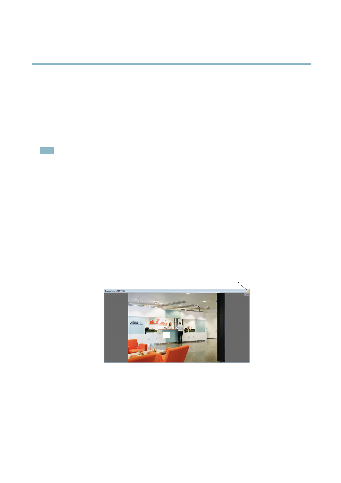
Manual Recordings
A manual recording can be started and stopped from the Live View workspace or the Actions menu:
• Open the Live View workspace and click the
over the camera's live view frame. C
•FromtheActions menu, o
Click Stop to stop recording.
During manual recording, a yellow indicator appears in the upper right hand corner of the live view image.
To configure manual recording settings, follow these steps:
1. From the Configuration menu, select Recording Settings.
2. Select the camera and click Manual to open Edit Manual Recording Settings.
3. Choose a Profile from the drop-down list or click Change to create a new media profile.
4. Use the sliders to set the Prebuffer and Postbuffer, that is, the number of seconds to include before starting (prebuffer) and
after stopping (postbuffer) the manual recording.
5. Click OK to save settings.
pen the Record Manually dialog. Select one or more cameras and click Start to start recording.
lick the button again to sto p recording.
button that appears in the upper right corner when the mouse pointer is
27
Page 28

AXIS Camera Station
How to...
Note
Multiple cameras can be configured at the same time.
Motion Triggered Recording
Motion can be detected by all Axis network cameras. Recording only when motion is detected will save disk space compared to other
options such as recording continuously. Motion Detection Recording can be configured using the Event Configuration Wizard, see
page 43, or the Recording Settings dialog as described here.
To set up a motion triggered recording, follow these steps:
1. From the Configuration menu, select Recording Settings.
2. Select the camera and click Motion Detection to open Edit Motion Detection Recording Settings.
3. Check the Enabled box.
4. Use the slider to set the Trigger period, that is, specify the minimum time between two alarms. This setting is used to
reduce the number of alarms and recordings if there is a lot of motion in the area.
5. Click Motion Settings to confi gure motion detection windows. See Motio n Settings,below.
6. Choose a Profile from the drop-down list or click Change to create a new media profile.
7. Use the sliders to set the Prebuffer and Postbuffer, that is, specify the number of seconds to record before motion was
detected (prebuffer) a nd after motion stopped (postbuffer).
8. Under Schedule setting select Always to always record on motion detection, or select a schedule from the Custom
schedule drop-down list.
9. Click OK to save settings.
Note
When using view areas, motion detection can be configured for view area 1 only and is always set up using the full overview
image.
28
Page 29

AXIS Camera Station
How to...
Motion Settings
Moving objects will be detected in the configured motion detection windows:
• Include windows define areas where motion should be detected
• Exclude windows define areas within an include window that should be ignored (areas outside include windows are
always ignore d)
For each motion detection window you can configure:
Object size - Object size is relative to the region size. At a high level, only very large objects are detected. At a low level even
very small objects trigger an event.
History - History defines how long an object needs to be in a region before it is considered to be non-moving. At a high level an
object that appears in the region will trigger the motion detection for a long period before it is considered a non-moving part of the
image. At a low level an object that appears in the region will trigger motion detection for only a very short period.
Sensitivity - Sensitivity defines the difference in luminance between the background and the object. At a high level, an ordinary
colored object on ordinary backgrounds will trigger motion. At a low level, only very bright objects on a dark background or
very dark objects on a light background will trigger an event.
To set up motion detection windows, follow these steps:
1. Click Motion Settings to open the Edit Motion Detection dialog.
2. Click Add to create a new motion detection window. Select Include to create an include window or select Exclude
to create an exclude window, as required.
3. Use the mouse to drag the window to the desired area. To resize, drag the sides of the window.
4. Set the Object size, History and Sensitivity.Beginwithapredefined setting and if needed fine adjust the settings using the
sliders while looking in the Activity window while there is a desired amount of motion in the motion detection window.
5. Click OK to save settings.
29
Page 30

AXIS Camera Station
How to...
Failover Recordings
A failover recording starts automatically if the connection between the camera and AXIS Camera Station is lost during an ongoing
recording. No new recordings can be started while the connection is lost.
Failover recordings will only affect H.264 recordings and can be enabled on cameras with support for storage (SD card) and firmware
5.20 or later.
To set up a failover recording, follow these steps:
1. From the Configuration menu, select Recording Storage.
2. Under Cameras, select t he camera and click Edit.
3. Check Enable failover recording.
4. Click OK to save settings.
Set Up Recording S
Recordings can be stored on a server disk on the local computer or on a network disk. To prevent the hard drive from becoming full a
maximum disk usage should be set. Additional server and network disks can be added for security and more space.
Note
Maximum drive space has precedence over the number of days to keep recordings. Recordings will be deleted if there is no
room left in the allotted drive space.
torage
30
Page 31

AXIS Camera Station
How to...
Configure a Recording Disk
To add and configure a recording disk, follow these steps:
1. From the Configuration menu, select Recording Storage.
2. Click Add server disk or Add network disk.
3. Enter the path of the disk and click OK to save.
4. To set the maximum disk space allowed to be used by AXIS Camera Station, select the disk and use the AXIS Camera
Station Recordings Limit slidebar.
5. To change the folder where recordings will be stored, select the disk and click Edit to specify new folder.
Configure Camera Recording Storage Settings
To specify storage settings for individual cameras, follow these steps:
1. From the Configuration menu, select Recording Storage.
2. SelectacamerafromCameras.
3. Click Edit to open the Edit Camera Recording Storage Settings dialog.
4. Choose the disk to save recordings to from the list Record to disk.
5. Set the number of days to keep recordings. By default the recordings are set to ‘Unlimited’.
6. Optionally, check the box to enable failover recordings.
7. Click OK to save settings.
To enter default storage settings for all newly added cameras, click Default Settings under Cameras.
Create Views
AXIS Camera Station supports different view types: split view, sequence, camera view, map and web page, see Views, on page 9 .The
views can be organized i nto view groups, see View Groups, on page 10.
31
Page 32

AXIS Camera Station
How to...
Create a New View Group
To create a View Group, follow these steps:
1. In the Live View workspace, right-click My Views or Shared Views in the View Groups pane.
2. Choose NewViewGroup.
3. Enter a descriptive name for the group.
4. Click OK to save and close the dialog.
To add a Map, Sequence or Split View follow the instructions Create a Map, Create a Sequence or Create a Split View.
Create a Split View
To create a split view, follow these steps:
1. In the Live Vie w workspace, right-click My Views, Shared Views or a created view group and choose New Split View
2. Enter a descriptive name and choose a layout from the drop-down list:
- Standard — optimized for standard resolution cameras (4:3 format)
- Wide — optimized for HDTV and megapixel cameras (16:9 format)
- Corridor — optimized for HDTV and megapixel cameras where the image has been rotated by 90 degrees (16:9 format,
90 degree rotation)
3. Drag cameras, views and maps to the desired camera views into place.
4. Click OK to save settings and close dialog.
You can define a frame in the view as a Hotspot that will automatically load the view from another camera when it is clicked on. This
is particularly useful for asymmetric views with one large view frame and several smaller views. The large view frame is typically
defined as the hotspot. To define a hotspot, click in the desired section of the view and click Set Hotspot.
32
Page 33

AXIS Camera Station
How to...
In the image below the large frame is the hotspot, and when another frame in the Split View is clicked, the Live View of that camera
will load in the hotspot. In this example the camera view shown in the hotspot is the Entrance.
Create a Sequence
A s equence view automatically switches between views from different cameras. Each sequence can be set as a unique combination of
camera views and variable dwell times.
To create a sequence, follow these steps:
1. In the Live Vie w workspace, right-click My Views, Shared Views or a created view group and choose New Sequence.
2. Enter a descriptive name.
3. Drag the cameras, views and maps you would like included into Sequence Items .
4. To include PTZ presets, select a PTZ camera and click Set Properties.
5. To set the number of seconds the sequence will dwell on a camera’s Live View, click on the camera and click Set Properties.
6. Click OK to save settings and close dialog.
33
Page 34

AXIS Camera Station
How to...
Create a Map
A map gives a visual overview of the cameras in your installation. A map is an image, for example a drawing or a photograph, on
which you place cameras and views. Maps c an also be placed on other maps in a hierarchical structure.
To create a map, follow these steps:
1. In the Live View workspace, right-click My Views, Shared Views or a created view group and choose New Map.
2. Enter a descriptive name.
3. Click Import Map and enter the file name or browse to locate the file.
4. Drag views to the map.
5. Click OK to save settings and close the dialog.
To remove a view from the map, select the view and click Delete View.
34
Page 35

AXIS Camera Station
How to...
Create a Web Page View
ExternalwebapplicationscanbeintegratedintoAXISCameraStation by creating a web page view. Web pages c an, for example,
be shown in a split or a sequence together with live video.
To create a web page view, follow these steps:
1. In the Live Vie w workspace, right-click My Views, Shared Views or a created view group and choose New Web Page.
2. Enter a descriptive name.
3. Enter the complete Internet address of the web page to be displayed, for example, http://example.com/path.html
4. Click OK to save settings and close the dialog.
Note
Web pages cannot contain other views.
35
Page 36

AXIS Camera Station
How to...
Add a PTZ Preset Position
For cameras with pan/tilt/zoom (PTZ) functionality, preset positions provide quick access to predefined views. Preset positions can be
added to Sequence Views and can be used with the mechanical PTZ control.
To add a pres et position, follow t hese steps:
1. From the Configuration menu, select PTZ Settings.
2. Select a PTZ camera and click Configure.
3. Steer the camera to the desired view using the mechanical PTZ control or clicking in the Preview window.
4. Click Add and type a descriptive name. Click OK.
Note
•Presetsconfigured in A XIS Camera Station are stored in the camera together with presets configured using the camera’s
Setup pages.
•ThePresets list includes preset positions configured both in AXIS Camera Station and in the camera. Click Refresh
to update the list.
Enable Audio in Live View
To enable audio in Live V ie w, follow these steps:
1. From the Configuration menu, select Live View Settings.
2. Select a camera and click Edit.
3. From the Profile drop-down list, select a media profile where a udio is enabled. If there is no such profile, click Change
and create one. Selec
4. To enable audio i
boxes and select a media profile whe re audio is ena ble d. If there is no such profile, click Change and create one. Select
H.264 or MPEG-4; audio is not supported with M-JPEG.
5. Click OK.
t H.264 or MPEG-4; audio is not supported w ith M-JPEG.
n split views and sequences, click Large Splits to display the override settings. Check the appropriate
Enable Audio in Recordings
o enable audio in recordings follow these steps:
T
1. From the Configuration menu, select Recording Settings.
36
Page 37

AXIS Camera Station
How to...
2. Select a camera and click Continuous, Motion Detection or Manual.
3. From the Profile drop-down list, select a media profile where a udio is enabled. If there is no such profile, click Change
and create one. Select H.264 or MPEG-4; audio is not supported with M-JPEG.
4. Click OK.
Configure a Media Profi le
Media profiles are video and audio settings used for live view ing and recording.
To configure a media profile, follow these steps:
1. Choose a Format for the media profile from the drop-down list. The options that appear in the list depend on the formats
supported in the camera.
2. Select the Resolution to use. Depending on the camera, resolution can fall into different ranges. Resolution is a measure of
how much detail a digital image can hold; the greater the resolution, the greater the level of detail.
3. Changing the Compression level affects the amount of bandwidth require d. Lower compression improves image quality,
but uses more bandwidth and storage space.
4. Specify the desired Frame rate. The actual frame rate depends on the model of camera , network conditions and your
computer’s configuration. Check Max if you like to always use the maximum frame rate possible.
5. The Audio checkbox is visible if the selected camera supports audio or if an external audiodeviceisusedwiththecamera.
Audio is only available for MPEG-4 and H.264. Select this option to enable audio in live view or in recordings.
Note
You can define several media profiles for H.264 and M-JPEG v ideo, but only one for MPEG-4.
Override Media Profiles in Live View
The default media profile used in Live View can be overridden for split views and sequences. Using media profiles with lower
resolution, frame rate or compression can improve pe rformance, especially for large splits.
To change the override settings, follow these steps:
1. From the Configuration menu, select Live View Settings.
2. Select a camera and click Edit.
3. Click Large Splits to display the Overrides settings
4. Check or uncheck the appropriate boxes and select media profiles from the drop-down lists. Click Change to create a
new profile.
37
Page 38

AXIS Camera Station
How to...
Use A udio from an Auxiliary Device
Audio from an auxiliary device (for example AXIS P8221 Network I/O Audio Module) can be used together with live or recorded
video from a network camera.
Follow these steps:
1. Add the auxiliary device to AXIS Camera Stat ion, see Add Auxiliary Devices, on page 26.
2. Add the camera to AXIS Camera Station, see Add Cameras and Video Encoders, on page 24.
3. From the Configuration menu, select Add/Edit Cameras.
4. Select the camera and click Edit.
5. Select the auxiliary device from the External audio drop-down list.
6. Click OK.
7. Enable audio in the live view or recording settings, see Enable Audio in Live View, on page 36 and Enable Audio in Recordings,
on page 36.
Add Inputs and Outputs
External devices such as window sensors, glass break detectors or PIR s (Passive Infrared Detector) can be c onnected to camera inputs
and used for triggering alarms, recordings or messages. An output’s main function is to trigger external devices such as a door relay
that controls door locks, or an alarm siren. For more information about input/output ports, refer to the camera's User Manual.
To add an I/O port to AXIS Camera Station, follow these steps:
1. From the Configuration menu, open I/O Settings.
2. Click Add to open a dialog with list of available I/O ports in existing devices.
3. Click to select the desired input or output port.
4. Click OK.TheAdd I/O Port dialog opens.
5. Enter a descriptive name for the port and for the active and inactive states. The names will appear under Logs, I/O
Monitoring dialog and Event Configuration Wizard. Refer to the camera’s U ser Manual about how the I/O ports were defined
for setting descriptive name s to the active/inactive states.
6. For output ports, check On startup set to to set the initial s tate of the output port. Choose the initial state of the Output
port from the drop-down list.
7. Click OK to save settings.
Note
e than one port is selected, the Add I/O Port dialog will not open. The ports will be added using default values.
If mor
Output ports can be set to an initial state upon startup and when AXIS Camera Station establishes contact with the camera.
38
Page 39

AXIS Camera Station
How to...
Set Up Schedules
Timetables can be set up to be used in Event Confi guration Wizard and Recording Settings. Once a schedule has been entered, it can
be reused as often as necessary. On special dates, for example public holidays, special schedules can be used.
To set up a schedule, follow these steps:
1. From the Configuration menu, select Schedules.
2. Click Add to open the Schedule Editor.
3. Enter a descriptive name for the schedule.
4. Click and drag on the timelines to define intervals. A blue bar means the schedule is on while white means the schedule is o ff.
5. To use a different schedule for special dates, click Override. Select the special dates and click Edit to set up the schedule.
6. Click OK to save.
39
Page 40

AXIS Camera Station
How to...
Send E-Mail Notification on System Alarm
A system alarm occurs when connection to a device is lost, when access to a recording disk is denied, when a recording disk is full, on
recording errors, etc. An e-mail notification can be sent when a system alarm occurs.
To set up e-mail notification, follow these steps:
1. From the Configuration menu, open System Alarm
2. Check Send e-mail on system alarm to the following recipients.
3. Enter t he e-mail addresses alarm messages should be sent to.
4. Under New recipient, choose if the address should be in the To, Cc or Bcc fieldofthee-mailandenterthee-mailaddress.
5. Click Add to enter the e-mail address into the Recipients box.
6. Click OK to save.
Note
To send emails, an SMTP server must first be added. To add an SMTP server, select SMTP Servers from the Options menu.
Export Recordings
Recordings can be exported to a local disk, a network location or b urned to a CD or DVD. Multiple recordings can be exported at
thesametime.
Exported recordings are ASF files and can be played by, for example, AXIS File Player and Windows Media Player. AXIS File Play er is
freesoftwareandcanbeincludedwith the exported recordings. AXIS File Player can be run without computer administrator rights;
no installation is required.
To export a recording, follow these steps:
1. In the Recordings workspace, select the recordings to be exported. To export a part of a recording, set a time interval
using the selection start and end markers.
2. Open the Actions menu and select Export Selected Recordings.
3. Browse to the local disk or network location, or select Burn recordings to burn to a CD or DVD.
4. Optionally, select include setup fi le for decoders. Decoders must be installed to view H .264 and MPEG-4 video.
5. Optionally, select Create playlist to create a playlist for Windows Media Player.
6. Optionally, select IncludeAXISFilePlayerto include AXIS File Player with the exported recordings.
7. Optionally, add a digital signature.
8. Click OK.
Note
• The selection start and end marker s are available in the Playback and Timeline tabs.
• Recording export can also be scheduled. Open the Configuration menu and select Scheduled Recording Export.
Upgrade Firmware
Firmware is software that determines the functionality of electronic devices. Always us e the latest firmware to ens ure that your
device has the latest functionality and improvements.
With an Internet connection, you can check for updates and download firmware directly via AXIS Camera Station Client. If the
client is installed on a computer without access to the Internet, new firmware can instead be imported from a file (for example on a
hard disk or memory stick).
40
Page 41

AXIS Camera Station
How to...
Devices will be offline during firmware upgrade. When upgrading multiple devices you can choose to upgrade in
• Sequence — one device at a time
• Parallel — upgrade all devices. This option is faster but all selected devices will be o ffline at the same time.
To upgrade one or more devices, follow these steps:
1. Navigate to the Camera Management w orkspace.
2. Select the devices you want to upgrade.
3. Open the Actions menu and select Upgrade Firmware.
4. To check if new firmware versions are available for download, click Check for Updates. You will be asked to enter the user
name and password for your MyAxis account. If you do not yet have an account, you can create one from this dialog.
5. For each device model, click the arrow under Upgrade To and select the firmware versions the devices should be upgraded
to. The following options can b e available in the drop-down list:
- Firmware that has already been downloaded or imported is shown with its version number.
- Firmware that is available for download is shown with the text (Download) after its version number. The firmware will be
downloaded automatically when you click OK to start the upgrade operation.
- Firmware that is available for import is shown with the text (Import) after its version number. The firmware will be
imported automatically when you click OK to start the upgrade operation.
- Browse —Ifthefirmware file is not available for import, select this option and browse to loca te the file.
6. Click Options and select to upgrade in parallel or sequence.
7. Click OK to start upgrading the devices.
Note
To check for updates, download or import firmware without upgrading devices, open the File menu, select Import/Export
and then Firmware.
41
Page 42

AXIS Camera Station
How to...
Assign IP Addresses
The Camera Management workspace allows you to configure IP addresses for multiple devices at the same time. You can
• Obtain IP addresses automatically from a D HCP server
• Search for available IP addresses in a specified range
To assign IP addresses to multiple devices, follow these steps:
1. Navigate to the Camera Management w orkspace.
2. Select the devices that you want to configure.
3. Open the Actions menu and select Assign IP Address.
4. Select one of the following options:
- Obtain IP addresses automatically (DHCP)
- Assign the following IP address range:
Specify the IP address range, the subne
5. Click Next.
6. The current IP address
device, select the device and click Edit IP.
7. Click Finish when satisfied with the new IP addresses.
and the new IP address are displayed under New IP addresses. To modify the IP address for a
t mask and the default router. Wildcards can be used, for example 10.93.*
Register a MyAxis Account
MyAxis is your personal area on Axis web site. From M yAxis you can download firmware and free software a pplications, submit
ions to customer support, subscribe to e lectronic newsletters etc.
quest
o register an account, go to http://www .axi s.com/r eg/register.php and enter the required information.
T
42
Page 43

AXIS Camera Station
Event Configuration Wizard
Event Configuration Wizard
Event Configuration Wizard helps you set up rules for triggers and actions in AXIS Camera Station. By setting up a rule you can assign
actions to triggers; for instance when motion is detected, a siren will sound and recording will begin on designated cameras.
Triggers are classifi ed as:
Motion Detection A motion detection event is triggered when an Axis camera detects motion within its defined area.
DetectionisperformedbythecamerawhichmeansnoprocessingloadtoAXISCameraStation.
Active Tampering Ala rm An active tampering alarm occurs when the camera is repositioned or when the lens is covered,
sprayed or severely defocused.
AXIS Cross Line Detection An AXIS Cross Line Detection event is triggered when a camera detects moving objects that
System Event and Error
Advanced triggers:
cross a virtual line. See notes below.
A system event and error triggers on recording error s, when connection to a camera is lost, access
to the recording disk is denied or when the recording disk is full.
Input/Output Input/Output is when a camera's I/O port receives a signal from an external d evice , such as a
doorbell, smoke detector or switch.
Device Event Trigger The device event trigger is intended for advanced users and can be used if no other trigger is
applicable. This trigger allows you to select any event a vailable in a camera, for example events
from applications uploaded to cameras with support for AXIS Camera Application Platform. For
Actions are classified as:
Record
Raise alarm
Set Output Set the state of an output port. This can be used to control an external device connected to the port.
Send e-mail Send an e-mail notification to one or more recipients. Snapshots can be atta
Live view
Note
• I/O ports must be added to AXIS Camera Station before being used in the Event Configuration Wizard. See Add Inputs
and Outputs, on page 38.
• Active Tampering Alarms are supported by products with tampering capabilities and firmware 5.11 and later.
• AXIS Cross Line Detection is an application that must be uploaded to the network camera or vide o encoder. The application
can be uploaded to products with support for AXIS Camera Application P latform. For more information, refer to AXIS
Cross Line Detection User’s Guide.
• Device event triggers are supported by products with firmware 5.40 and later.
Start a recording from a specified camera.
Send an alarm to all connected clients. An alarm procedure can be included.
Open a specific view, camera or PTZ preset position.
information about available events, refer to the camera’s help files.
ched.
Create a Rule
The example described in this chapter demonstrates how to use the Event Configuration Wizard to create a rule that starts a
recording, raises an alarm and sends an e-mail each time a door is opened. The door switch is connected to an input port of the
camera monitoring the door.
Start by creating a new rule:
1. Open the Configuration menu and select Event Configuration.
2. Click New to open the New Rule dialog.
43
Page 44

AXIS Camera Station
Event Configuration Wizard
Theruleisconfigured in four steps, described in the following sections:
• Triggers — add one or more triggers
• Actions — add one or more actions
• Schedule — select a schedule for the rule
• Details — check settings and enable the rule
Add Triggers
A rule can have one or more triggers. When using several triggers, only one of the triggers needs to become active to activate the rule.
In this example, an I/O trigger will be cre ate d.
Add an I/O Trigger
To create an I/O trigger, follow these step
1. In the New Rule dialog, click Add to op
2. Click Advanced and selec
3. Select the input por
the door is open (the state Active in this example). A vailable values d epend on how the I/O port was defined under
Configuration > I/O Settings.SeeAdd Inputs and Outputs, on page 38 for more information.
4. Since the trig ger can go off many times and create unwanted e vents, an option is to set the Trigger period slider so that
any trigge
rs that come in under this period will be treated a s one trigger.
t on the camera monitoring the door and select thetriggerstatethatwillactivatetherulewhen
s:
en the A dd Trigger dialo g.
t Input/Output. The Create I/O Trigger dialog opens.
k OK to save the trigger settings.
5. Clic
hen all triggers have been added, click Next to move to the Actions step.
6.W
44
Page 45

AXIS Camera Station
Event Configuration Wizard
Add Actions
The rule can have one or more actions. In this example, three actions will be created: record, raise alarm and send e-mail.
Add a Recording Action
To create a recording action, follow these steps:
1. In the New Rule dialog, Actions step, click Add and select Record.
2. In Create Recording Action select the camera that should start recording. In this example, Entrance.
3. Select the Video setting profile from the drop-down list or click Change to enter a new profile. See Configure a Media
Profile, on page 37 for more information.
4. With the sliders select the number of seconds to include before the trigger (Prebuffer) and after the trigger stops (Postbuffer).
5. Click OK.
45
Page 46

AXIS Camera Station
Event Configuration Wizard
Add a Raise Alarm Action
To create a raise alarm action, follow these steps:
1. In the New Rule dialog, Actions step, click Add and select Raise alarm.
2. Type a title for the alarm message and a description.
3. To include an alarm procedure, select Alarm procedure, click Upload andbrowsetolocatethefile.
4. Click OK to save.
Note
An alarm procedure is an uploaded file, for example a text or image file.
Add a Send E-Mail Action
Note
To send e-mails from AXIS Camera Station an SMTP server must first be added. Open the Options menu and select SMTP
servers.
To create a send e-mail action, follow these steps:
1. In the New Rule dialog, Actions step, click Add and select Send e-mail.
2. Enter the e-mail addresses that alarm messages should be sent to. Under New Recipient, c hoose if the address should be in
the To, Cc or Bcc fieldofthee-mailandenterthee-mailaddress.
3. Click Add to enter the e-mail address into the Recipients box.
4. Enter a subject for the e-mail in the Subject field.
5. Enter a message to the recipient.
46
Page 47

AXIS Camera Station
Event Configuration Wizard
6. To attach camera snapshots, select Attach snapshots and click Cameras to select the cameras to include snapshots from.
7. To reduce the number of e-mails, select Send one e-mail for each event or Don’t send another e-mail for.
8. Click OK to save.
Set a Schedule
Therulecanbeconfi gured to be active at all times or according to a schedule. F or more information
Schedules, on page 39.
To set a schedule, follow these steps:
1. When all actions have been added, click Next to move to the Schedule step.
2. Select Always to let the rule be active at all times or sele ct a Custom Schedule
3. Click Next to go to the Details step.
Rule Details
The final Details step shows the rule setting s.
1. Enter a Name for the rule.
2. Check that all settings are correct.
3. Make sure that Enable this rule is selected and click Finish to save the rule.
about schedules, see Set Up
47
Page 48

AXIS Camera Station
Event Configuration Wizard
48
Page 49

AXIS Camera Station
Network and Security Configuration
Network and Security Configuration
If AXIS Camera Station Client, AXIS Camera Station Server and the connected network devices are installed on different netw orks you
mightneedtoconfigure the proxy and/or firewall settings.
• If the client and the server are separated by a proxy server, the client proxy settings should be modified, see Client Proxy
Settings, on page 50.
• If the client and the server are separated by a NAT, firewall or similar, the NAT or firewall should be modified, see NAT
and Firewall,below.
• If network devices and the server are separated by a proxy server, the server proxy settings should be modified, see
Server Proxy Settings,below.
If your local network uses a proxy for Internet connection, you might need to configure the proxy settings to:
• register licenses using the auto matic registration option (server proxy settings)
• check for and download firmware updates (client proxy settings).
To prevent unauthorized access to the connected network devices, AXIS Camera Station has a high degree of security with multiple
access levels us ing Windows Active Directory, see User Permissions, on page 51.
NAT and Firewall
If there is a NAT, firewall or similar that separate s the server from the client you might need to configure the NAT and/or firewall to
allowaccesstothenetwork.Makesuretheserverportandstreamingport(seeServer Port Configuration, on page 51) are allowed to
pass through the firewall and/or NAT. For instructions, contact your network administrator.
Note
Some antivirus programs also block applications from accessing the network, similar to a firewall. To configure your antivirus
program to allow the client and/or server network access, refer to the documentation provided with your program.
Server Proxy Settings
The server proxy settings need to be config
• AXIS Camera Station Server and the n
• your network us es a proxy for I
ured if:
etwork video devices are separated by a proxy server
nternet connection and you want to register licenses.
Devices outside of the local network. To access the devices on the other side of the proxy server from AXIS Camera Station, you must
configure the server proxy settings.
49
Page 50

AXIS Camera Station
Network and Security Configuration
To configure the server proxy settings, follow these steps:
1. Open Service Control from Start > All Programs > AXIS Camera Station 3 > AXIS Camera Station Tools.
2. Check the box Modify server settings.
3. Under Proxy settings, select Use manual proxy settings.
4. Enter the address and port number of the proxy server. This is usually the sa me address and port number as under Internet
Options in Windows Control Panel.
5. If there are local devices that do not go through the proxy server, check Bypass proxy for local addresses and enter the
devices’ addresses in the b ox separated by semicolons.
Note
If you don’t know your proxy server settings contact your network administrator.
For more information on AXIS Camera Station Service Control, see page 58.
Client Proxy Settings
The client proxy settings need to be configured if:
• AXISCameraStationClientandAXISCameraStation Server are separated by a proxy server
• your network uses a proxy for Internet connection and you want to check for and download firmware updates.
AXIS Camera Station Client behind a proxy. To connect to an AXIS Camera Station Server on the other side of the proxy, the client proxy
settings must be configured.
To configure the client proxy settings, follow these steps:
1. Open the File menu and select Client Proxy Settings.
2. Select the appropriate option depending on your setup
- Direct connection — This option should be checked if there is no proxy server between AXIS Camera Station Client
- U
- Use manual proxy settings — This option allows you to fill in the required information manually under Manual settings.
XIS Camera Station Server.
and A
se Internet Explorer settings — AXIS Camera Station will use the same proxy settings as Internet Explorer
50
Page 51

AXIS Camera Station
Network and Security Configuration
3. If Manual settings was selected, enter the proxy server’s IP address/host name and port number. If there are local servers
that do not go through the proxy server, check Bypass proxy for local addresses and enter the servers’ addresses in
the box separated by semicolons.
Server Port Configuration
The ports 55752 (control) and 55753 (media streaming) are used on the AXIS Camera Station Server computer for communication
between the server and the AXIS Camera Station Client. If required, the ports can be changed from AXIS Camera Station Service
Control, see AXIS Camera Station Service Control, on page 58.
User Permissions
Using Windows Active Directory, a high level of security can be implemented in AXIS Camera Station when granting user permissions.
Before users can be granted access to AXIS Camera Station, they must be added to the local computer or have an Active Directory
user account.
A user can be g ranted access as an individual or as part of a group. In cases where a user is granted access as an individual he will
retain this right plus receive the rights he re ce ives as pa rt of a group. For ex ampl e, a user is given acces s to camera X as an individual.
The user is also a member of a group. The group is given access to cameras Y and Z. The user then has access to cameras X, Y and Z.
Administrators of the computer on which the AXIS Camera Station Server is installed are automatically given administrator privileges
to AXIS Camera Station. It is not possible to change or remove the administrators group's p rivileges.
To configure user access rights, open the Configuration menu and select User Permissions.
Local Security
By default, local security is Disabled which means all users, who log onto AXIS Camera Station Server installed on the same computer
as the AXIS Camera Station Client, will be given Administrator access. When local security is Enabled, access to AXIS Camera Station
is restricted to trusted use rs and groups for both remote and local clients. For remote clients, local security is always enabled.
To change the local security settings, open the Configuration menu, select User Permissions and click Security Settings.
Add a User or a Group
To add a user or a group, follow these steps:
1. Open the Configuration menu and select User Permissions.
2. Click Add to open the Add User/Group dialog.
3. Select the AXIS Camera Station Server or Domain. The available users and groups are listed under Available domain
users/groups.Tonarrowthelist,selectUsers or Groups.
4. Select a user or group from the list and click Add to open the User/Group Privileges dialog.
5. Select an authority level for the user:
- Administrator - Full access to all functionality of AXIS Camera Station and added cameras.
- Operator - Full access to all f unctionality of AXIS Camera Station except Configuration pages, the camera management
workspace and audit logs. Full access to selected cameras and I/O ports.
- Viewer -AccesstoselectedLiveViewsandI/Oports.
6. Optionally, select the cameras and I/O ports that theoperatororviewershouldhaveaccessto.ClickAdvanced to give
access to individual features.
51
Page 52

AXIS Camera Station
Network and Security Configuration
Note
• If the domain user search fails, make sure that AXIS Camera Station Service is logged on as a Windows user with
access to the Active Directory. To change the user account for AXIS C amera Station Service, go to Control Panel >
Administrative Tools > Services.
• For Input/Output ports to be visible here, they must first have been added to AXIS Camera Station. See Add Inputs
and Outputs, on page 38.
52
Page 53

AXIS Camera Station
Input Devices
Input Devices
The following input devices can be used with AXIS Camera Station:
• AXIS T8311 Video Surveillance Joystick
• AXIS T8312 Video Surveillance Keypad
• AXIS T8313 Video Surveillance Jog Dial
• AXIS 295 Video Surveillance Joystick
Hotkeys
Hotkeys give quick access to commonly used actions. A hotkey can be
• a keyboard combination
• a keypad combination
• a joystick button
• a jog dial button
To display a list of all currently assigned hotkeys for all input devices, open Assigned hotkeys from the Help menu.
Hotkeys defined as Global are available in all workspaces; other hotkeys are available in only one workspace.
To add, edit and remove ho tkeys, open Hotkeys from the Options menu. Click Restore defaults to reset the hotkey configuration to
default.
AXIS T8311 Video Surveillance Joystick
AXIS T8311 Video Surveillance Joystick is a USB device that can used
• to pan, tilt and zoom in the camera view (cameras with mechanical PTZ only)
• as a computer mouse
Connect the joystick before you start AXIS Camera Station. The joystick is detected and installed automatically.
Note
If the joystick is connected after AXIS Camera Station has been started, click Refresh in the Live V ie w workspace.
You can configure the joystick to toggle between the PTZ and mouse modes. G o top Options > Hotkeys,selectJoystick and then
Add. Select Global, Turn on/off joystick PTZ controlling and assign an unused joystick button.
The table below lists the default configuration for joystick hotkeys.
53
Page 54

AXIS Camera Station
Input Devices
AXIS T8311
Button
J1
J2
J3
J4
L Left mouse button
R Right mouse button
Function (Global) Function (Live View) Function (Recordings)
Go to preset 1
Go to preset 2 Stop
Go to preset 3
Go to preset 4
Play/Pause
Jump to prev ious recording start
Jump to next recording start
AXIS T8312 Video Surveillance Keypad
AXIS T8312 Video Surveillance Keypad is a USB device used to quickly navigate between workspaces, cameras, views and PTZ presets.
Connect the keypad before you start AXIS Camera Station. The keypad is detected and insta lled automatically.
Note
If the keypad is connected after AXIS Camera
The table below lists the default configuration for keypad hotkeys.
Station has been started, you must restart the application.
54
Page 55

AXIS Camera Station
Input Devices
AXIS T8312
Key
F1
F2 Navigate to Live View
F3 Navigate to Recordings
F4 Navigate to Logs
F5
View
Camera Go to next camera view.
Preset
Time
Tool
Tab
Function (Global) Function (Live View) Function (Recordings)
Navigate to Start page
Navigate to Configuration
Go to the next user-created
view (in My Views or Shared
Views).
Press 3+
number 3.
Press ALT+ to go to the
previous view.
Press 3+
number 3.
Press ALT+
previous camera view.
elect the next alarm in the
S
alarm list.
Press ALT+
previous alarm in the list.
to go to view
to go to camera
to go to the
to select the
Go to the next PTZ preset of the
currently selected camera
Press 3+
Navigate forward in a split view.
Press ALT+
backward.
to go to PTZ preset 3.
to navigate
.
Enter a time (format hhmm) and press this
key to start playback from the corresponding
time.
Example: 2000+
20:00 (8 pm).
starts playback from
55
Page 56

AXIS Camera Station
Input Devices
The View, Camera, Preset, Time and Tool keys are backlit when the keys can be used. For example, the Time key is b acklit when
you are in the Recordings workspace.
AXIS T8313 Video Surveillance Jog Dial
AXIS T8313 Video Surveillance Jog Dial is a USB device used to jog and shuttle through recorded video.
Connect the jog dial before you start AXIS Camera Station. The jog dial is detected and installed automatically.
Note
If the jog dial is connected after AXIS Camera Station has been started, you must restart the application.
The table below lists the default configuration for jog dial hotkeys.
AXIS T8313
Button
Bookmark
Go to previous
Play/Pause
Go to next
L Take a snapshot
R Toggle search
AXIS 29
AXIS 295 Video Surveillance Joystick is a USB device that can used
Connect the joystick before you start AXIS Camera Station. The joystick is detected and installed automatically.
5 Video Surveillance Joystick
• to pan, tilt and zoom in the camera view (cameras with mechanical PTZ only)
• as a computer mouse
Function (Global) Function (Live View) Function (Recordings)
Add a bookmark
Recordings search: Select the previous recording.
Playback: Go to previous track of a recording.
Recordings search: Play selected recording.
Playback: Play and pause playback.
Recordings search: Select the next recording.
Playback: Go to next track of a recording.
56
Page 57

AXIS Camera Station
Input Devices
Note
If the joystick is connected after AXIS Camera Station has been started, click Refresh in the Live V ie w workspace.
You can configure the joystick to toggle between the PTZ and mouse modes. Go to Options > Hotkeys,selectJoystick and then Add.
Select Global, Turn on/off joystick PTZ controlling and assign an unused joystick button.
AXIS 295
Button
F1
F2
F3
F4
F5 Left mouse button
F6 Right mouse button
F7
F8 Toggle full screen Take a snapshot
F9 Navigate back
F10
F11 Increase joystick speed. Keep
F12 Reduce joystick speed. Keep
Function (Global) Function (Live View) Function (Recordings)
the button pressed while
moving the joystick.
the button pres
moving the joystick.
sed while
Go to preset 1
Go to preset 2 Stop
Go to preset 3
Go to preset 4
Show split/single view Show split/single view
Start/Stop manual recording
Play/Pause
Jump to previous recording start
Jump to next recording start
57
Page 58

AXIS Camera Station
AXIS Camera Station Service Control
AXIS Camera Station Service Control
AXIS Camera Station Service Control is the application that controls the AXIS Camera Station Service. The Service Control is started
when the user logs on to Windows and is located in the system tray. In most installations, the Service Control’s default settings a re
sufficient, but in some cases (see page 49 for details) the prox y settings will need to be ad justed.
Thesystemtrayiconwilldisplayservice changes, e.g. if the service is started
service control; double-click the icon in the system tray, right-click and select Open AXIS Camera Station Service Control from the
pop-up menu or from Windows Start > All Programs > AXIS Camera Station 3 > AXIS Camera Station Tools > Service Control.
or stopped . There are three ways to open the
In addition to modifying the server settings, the AXIS Camera Station Server Control allows you to start, stop and restart the server.
See also AXIS Camera Station Service Administration, on page 61.
Modify Server Settings
To change service settings, check the box Modify server settings.
Click Restore Default Settings to restore the default values for the server, streaming ports and proxy settings.
Server Settings
Under Server settings enter the ports the server will use to communicate with the clients. The streaming port is used for video
streaming, for example sending l ive video or playback from the server to the client. If there is a NAT or proxy between the server and
clients, the ports must be configured to let communication pass through.
Note
The server port number must lie in the range 1024-65534.
58
Page 59

AXIS Camera Station
AXIS Camera Station Service Control
Once satisfied with the changes click Save. You will be prompted to restart the service for the changes to take effect.
Database Backup
The database stores info rmation about configurations, recordings etc that is needed for AXIS Camera Station to work properly. The
database is backed up every night. The backups are saved to a Backup folder which can be located on the local computer or the
network. To change the backup folder, click Browse and navigate to the desired location. The oldest backups will be deleted
afterthenumberofdaysspecified in Days to keep backups.
Note
• The backup will be saved to the default location if it cannot be written to the folder specified, for example i f the server
cannot access the folder. The default location is
Windows 7/Vista/Server 2008/Server 2003:
C:\ProgramData\Axis Communications\AXIS Camera Station S erve r\backup
Windows XP:
C:\Documents and Settings\All U sers\Application Data\Axis Communications\AXIS Camera Station Server\backup
• The backup files are named acs_system_<date_time>.fdb and license_system_<date_time>.fdb
• Recordings are stored in the location specified in Configuration > Recording storage and not in the database, see Set Up
Recording Storage, on page 30. Recordings should be backed up separately.
For information on how to restore the database, see Lost data, on page 66.
Proxy Settings
If there is a direct connection with the cameras in the system the default Direct connection radio button should be selected. If
AXIS Camera Station Server is behind a proxy server, and devices are outside the proxy server, modify the proxy settings manually
by selecting Use manual proxy settings. The proxy settings entered here are generally the same as those entered in t
Options in the Control Panel.
Check the box Bypass proxy for local addresses and enter lo cal addresses or host names of local cameras where communication does
not need to pass through the proxy server. For more information, see Server Proxy Settings, on page 49.
he Internet
59
Page 60

AXIS Camera Station
AXIS Camera Station Service Control
Server Status
Server status shows the current status of the AXIS Camera S tation Server. The buttons Start, Stop and Restart change the server
status.
Developer API
The settings under the Developer API tab are intended for A XIS Camera Station SDK users. Please refer to Windows Development
on the Partner Pages at www.axis.com for more information.
60
Page 61

AXIS Camera Station
AXIS Camera Station Service Administration
AXIS Camera Station Service Administration
AXIS Camera Station Service Administration is a console a pplic ation that has the same functions as AXIS Camera Station Service
Control. It can be used from the command prompt or from a batch scripttostartandstoptheserviceorbackupthedatabase,etc.,
which allows for automating and scheduling of administrative tasks.
The default location of the console application is
"C:/Program Files/Axis Communications/AXIS Camera Station 3/AcsAdminConsole.exe”
Note
AcsAdminConsole.exe must be run as administrator.
Supported Operations
Command
AcsAdminConsole --help
AcsAdminConsole --backup
AcsAdminConsole
--backupcount=<number>
--backupdir=<path>
dminConsole --start
AcsA
AcsAdminConsole --stop
AcsAdminConsole --restart
Description
List a summary of the supported operations
Back up the database. Each backup generates
acs_system_<date_time>.fdb and license_<date_time>.fdb
Note: AcsAdminConsole backs up configurations a nd metadata but not
recordings.
For information on how to restore the database, see Lost data, on page 66.
Specify the number of backups to keep (this number affects the automatically
generated backups discussed on page 59, not the ones generated by the
--backup command).
Specify the folde r where the backups will be stored.
Start service
Stop service
Restart service
two timestamped files named
61
Page 62

AXIS Camera Station
AXIS Camera Station Service Administration
Command
AcsAdminConsole
--port=<port number>
AcsAdminConsole
--manualproxy
--proxyaddress=<proxy>
--proxyport=<port>
--bypassproxy=<true/false>
--bypassproxyaddresses=<addresses>
--disableproxy
Description
Set server port (e.g. AcsAdminConsole --port=55762)
Use manual proxy settings.
Set the proxy address and port (default 80).
Bypass proxy for local addresses. Example: bypassproxyaddress=192.*,
*mydomain.com
62
Page 63

AXIS Camera Station
Troubleshooting
Troubleshooting
Area zoom
Area zoom does not work
Area zoom is not supported by AXIS 209MFD and AXIS 212 PTZ. Use the digital or mechanical
PTZ controls instead.
Audio
There is no audio in Live View Make sure the camera ha s audio c apabilities.
Check that audio is activated in Live view settings:
1. From the Configuration menu, select Live View Settings
2. Click on the desired camera and then Edit to open Live View Settings
3. Click Change to open Change Media Profile .
4. Check the Audio box
Note: Audio is no t possible in M-JPEG; choose MPEG-4 or H.264.
Make sure the user has access rights to audio.
Note: To follow these steps you must have administrator rights to AXIS Camera Station
1. From the Configuration menu, select User Permissions
2. Select User or Group and click Edit
3. Click Advanced. Make sure that Audio is checked in the desired camera
Check that your computer has an audio card and that the card is not disabled.
There is no audio in split view s
larger then 6 split
There is no audio in sequence
views
There is no audio in playback Audio is available in playback only if audio was enabled in the media profile used for the
Audio is not available in split views larger than 6 splits when using the default Live View
settings. To change the default settings:
1. From the Configuration menu, open Live View Settings.
2. Select the desired camera an d click Edit to open Live View Settings.
3. Click Large Splits.
4. Change the s etting s under Overrides. Enable audio by changing the media profiles
Note: Audio is not possible in M-JPEG; choose MPEG-4 or H.264.
Sequence views use the media profile selected for 2–6 s plit views. To enable audio in sequence:
Note: Audio is not possible in M-JPEG; choose MPEG-4 or H.264.
recording.
Continuous, motion detection and manual recordings:
To enable audio:
Triggered recordings — Events
To
For information on how to set up rules, see Event Configuration Wizard, on page 43.
or uncheck the appropriate boxes to disable the overrides.
1. From the Configuration menu, open Live View Set
2. Select the desired camera an d click Edit to open Live View Settings.
3. Click Large Splits.
4. Check the 2–6 split views bo x and select a
5. Repeat steps 2–4 for all cameras included in the sequence.
1. From the Configuration menu, open
2. Select the desired camera and click Continuous, Motion Detection or Manual
3. Select a media profile where audio is enabled. If there is no such profile, click
Change and check the Audio box.
enable audio in an existing rule:
1. From the Configuration menu, open Event Configuration
2. Select the desired rule and click Edit
3. Select a media profile where audio is enabled. If there is no such profile, click
Change and check the Audio box
4. Click Finish to save.
Recording Settings
tings.
media profile where audio is enabled.
63
Page 64

AXIS Camera Station
Troubleshooting
Note: Audio is not possible in M-JPEG; choose MPEG-4 or H.264.
Missing AAC decoder To use the AAC audio format, a decoder must be installed. Click the link to install the decoder.
If using Demo m ode or AXIS Camera Station One, download the decoder from the camera’s
Live View page.
AXIS Cross Line Detection
AXIS Cross Line Detection does
not work
AXIS Cross Line Detection can be used with network cameras and video encoders that support
AXIS Camera Application Platform.
To use AXIS Cross Line Detection as a trigger, you must first
• upload the application to the camera
• start the application in the camera
For instructions, see AXIS Cross Line Detection User’s Guide.
Domain user search fails
Cannot find domain users Make sure that AXIS Camera Station Service is logged on as a Windows user w ith access to
Active Directory. To change the user account for AXIS Camera Station Service, go to Control
Panel > Administrative Tools > Services.
Graphics card
The graphics card driver is more
than 12 months old
Graphics card error
Graphics card warning The graphics card does not the minimum system requirements, see System Requirements.
For AXIS Camera Station client to run properly, it is important that the graphics card in your
computer has been updated with the latest driver.
To find out what graphics card is installed in your computer, a diagnostic program called
dxdiag can be used.
In Windows 7/Vista/Server 2008/Server 2003:
1. Open the Start menu
2. Enter dxdiag in the Start Search field
3. If a prompt appears for the Diagnostic Tool, click Yes
4. Select the Display tab. The name of the Graphics card appears under Device
In Windows XP:
1. Open the Start menu and select Run
2. Enter dxdiag in the Run dialog and click OK
3. If a prompt appears for the Diagnostic Tool, click Yes
4. Select the Display tab. The name of the Graphics card appears under Device
To download the latest driver you need to visit the graphics card manufacturer's web site.
Some of the more common ones are
• nVidia - www.nvidia.com
• ATI - www.ati.com
• S3 - http://www.s3graphics.com
To upgrade the graphics card drivers on your computer:
1. Download the drive
2. Make sure that there are no other programs running on your computer.
3. Run the installer and follow the wizard to install necessary files
4. Reboot to acti
The graphics card must support DirectX 9.0c, be Windows Vista compliant (even if running on
Windows XP) and support Windows Presentation Foundation tier 2.
r from the manufacturers web site to your hard drive
vate the change
64
Page 65

AXIS Camera Station
Troubleshooting
Live view
To check the graphics card’s tier level, open the Help menu and select Client Configuration
Sheet. Render Capability Tier is listed in the General Configuration Information section.
It is also possible to use the CPU for video rendering, instead of using the grap h ics card, see
Empty “ActiveMovieWindow” popup below.
No image from camera
Repeated error message "Media
Failed"
Empty “ActiveMovie Window”
popup
Proper decoders must be installed for MPEG-4 and H.264 video formats. In licensed mode, click
on the link in the empty Live View window to launch the decoder installation. In AXIS Camera
Station One or Demo mode, download the proper decoders fro m the camera’s Live View page.
Try reducing the load to the CPU by modifying the Live View Settings for each camera under
Configuration. Reduce the resolution, increase the compression setting and lower the fram e
rate.
Check that your computer is not running low on memory.
Check that the graphics card has been updated with the latest driver, see Graphics card,
on page 64.
Firewall and antivirus software sometimes block video signals. Check that your firewall and
antivirus program do not block the following files:
•AcsAdmin.exe
•AcsAdminConsole.exe
• ACSService.exe
• Server.exe
• AcsClient.exe
• All content of C:\Program Files\Axis Co mmunications\Components
See also NAT and Firewall, on page 49.
This indicates problems with the graphics card’s video memory and hardware acceleration.
Possible solutions:
• Install the latest graphics card driver, see Graphics card
• Upgrade to a graphics card with more video memory and higher performance
• Use the CPU for video rendering, see below.
To use the CPU for video rendering, follow these instructions:
1. Navigate to the AXIS Camera Station Client installation folder. The default
location is:
C:\Program Files\Axis Communications\AXIS Camera Station 3\Client <current
version>
2. Open the file AcsC lient
3. Find this entry:
<setting name=”ForceCompatibilityVideoMode”
serializeAs=
4. Change “False” to “True”
5. Save the file and restart AXIS Camera Station
.exe.configinatexteditor.
”String”><value>False</value></setting>
Logon/connecting to server
User name or password is
incorrect
ck that the user name and password are valid
Che
Check that the user has access rights to AXIS Camera Station Server
Check that the clocks in AXIS Camera Station Client and Server are synchronized. For domain
users, check that the domain server clock is synchronized with the server and client.
65
Page 66

AXIS Camera Station
Troubleshooting
AXIS Camera Station Server was
unable to verify message security.
Please make sure server and
client UTC times are reasonably
synchronized
Unable to connect to server.
Please make sure that the
server is running and accepting
connections.
Unable to locate the server
computer. Pleasemakesurethat
theservercomputerisconnected
to the network.
A user who has not been added to the server, but is a member of the local administrators
group on the server, must run the client as administrator on Windows 7/Vista. Right-click the
AXIS Camera Station Client icon and select Run as administrator.
The clocks in AXIS Camera Station server and client are not synchronized. Adjust the clock
in either the server or client so that they have the same date a nd time properties. For more
information on setting up time in your computer consult the Window’s help files.
Check that a NAT/firewall is not blocking a connection to the server
Check the address and port of the AXIS Camera Station server is correct.
Check that a NAT/firewall is not blocking a connection to the server
Check that the server is running.
Unable to connect to server! Verify that the computer the server and client are installed on is u p to date and has the
latest service packs/patches from Microsoft
Verify that the network is correctly installed and configuredontheserverandclient
computer(s)
Verify that no NAT/firewalls are blocking connection between AXIS Camera Station client
and server
Lost data
Data lost due to hardware f ailure
or other problems
The AXIS Camera Station database contains information about re
that is needed for the system to work properly. This database is backed up every evening.
Recordings are not stored in the database and should be backed up separately from the
locations designated in Recording Storage, see page 30.
If for some reason the database is lost due to hardware failure or other problems, the database
can be restored e ither with the latest backup or you can use a prior backup.
To restore the database follow these instructions:
1. Open AXIS Camera Station Service Control and click Stop.
2. Navigate to the folder where the backup files are stored. The path to this folder is
found under Database backup in AXIS Camera Station Service Control.
The backup folder contains timestamped backup files named
acs_system_<date_time>.fdb and license_system_<date_time>.fdb
3. Copy acs_system_<date_time>.fdb and license_system_<date_time>.fdb to
Windows 7/Vista/Server 2008/Server 2003: C:\ProgramData\AXIS
Communication\AXIS Camera Station Server\
Windows XP: C:\Documents and Settings\All Users\Application Data\Axis
Communication\AXIS Camera Station Server\
4. Delete the files ACS.FDB and LICENSE.FDB.
5. Rename acs_system_<date_time>.fdb to ACS.FDB and rename
license_system_<date_time>.fdb to LICENSE.FDB.
6. Click Start in AXIS Camera Station Service Control.
cordings and other metadata
66
Page 67

AXIS Camera Station
Troubleshooting
Menu item
Ican'tseetheConfiguration
menu
You do not have administrator privileges. Menu items are hidden from users that are not
granted access under User Permissions.
Playback problems
Not enough disk space to buffer Increase the buffer size:
1. From the Options menu, open Customize and select the Recordings tab
2. Under Playback buffering se lect Use at most and use the slider to increase the
buffer size
PTZ problems
Mechanical PTZ does not work
PTZ presets cannot be configured
Check that the camera’s PTZ control queue has not been enabled. If the control queue is
enabled, mechanical PTZ controls and PTZ presets are not available. To check if the control
queue is enabled, open the camera’s built-in web pages in a browser. For more information,
refer to the camera’s User Manua l available from www.axis.com
Recording storage
Network disk is not accessible
Network disk is listed as
"Unavailable"
To use network disks linking to shared folders on other computers, the Local System acco unt
cannot be used to log on to AXIS Camera Station S ervice. To change the service login account,
follow these instructions:
1. Go to Control Panel > Administrative Tools > Services
2. Right-click AXIS Camera Station and choose Properties
3. Click the Log On tab
4. Change from Local System account to This account
5. Choose a user with access to Windows Active Directory
The computer that AXIS Camera Station Server is installed on, should be part of the same
domain as the shared folder that is entered as a network disk.
Move AXIS Camera Station installation
How do I move my AXIS Camera
Station installation to another
server?
Contact Customer Suppo
Technical support is available for licensed versions of AXIS Camera Station with a valid support license. Open the Options menu
and select Licenses to check if you have a valid support license. If the suppo rt license has exp ire d , a new licen se can be obtaine d
from your Axis rese
If you contact A
to your online support case:
ller.
xis Customer Support, please help us resolve your problem expediently by zipping and attaching the following files
To move your current installation to another server please follow thes e steps:
1. Install AXIS Camera Station (same version) on the new server
2. Open AXIS Camera Station at the new location and do a new license registration.
3. Stop AXIS Camera Station Service, see page 58.
4. Move the file named ACS.FDB to the new location:
In Windows 7/Vista/Server 2008/Serve r 2003/64–bit versions the file is located
at C:\ProgramData\AXIS Communication\AXIS Camera Station Server.
In Windows XP the fi le is located at C:\Docu
Users\Application Data\Axis Communications\AXIS Camera Station Server
5. Move your recordings from the recording paths e.g C:\Recordings\ to the new
location.
Note: The recording paths must be exactly the same on the new server.
ments and Settings\All
rt
67
Page 68

AXIS Camera Station
Troubleshooting
Server Report To generate a Server Report, follow these steps:
Windows Event Logs:
Application and
System
Screenshots
If a Server Report cannot be generated, for example if AXIS Camera Station Server does not start, run DirectX Diagnostic Tool as
described below and provide debug logs with your supp ort case.
1. Open AXIS Camera Station Client.
2. From the Help menu, select Server Report.
3. Click OK to save the Server Report as a zip file.
To generate event logs, follow these steps:
Windows 7, Windows Vista, Windows Server 2008, Windows Server 2003
1. Click the Start button, right-click Computer and select Manage to open Computer
Management.
2. Select Event Viewer > Windows Logs and then Application.
3. From the Action menu, select Save All Events As and save as an event log (evt) file.
4. Repeat steps 2 and 3 but select System instead of Application.
5. Zip both files and attach them to your support case.
Windows XP
1. Click the Start button, right-click My Computer and select Manage to open Computer
Management.
2. Select System Tools > Event Viewer and then Application.
3. From the Action menu, select Save Log File As and save as an event log (evt) file.
4. Repeat steps 2 and 3 but select System instead of Application.
5. Zip both files and attach them to your support case.
To copy what is currently displayed on the screen to a file, follow these steps:
1. Press ALT - PRT SCR.
2. Open the Paint program included with Microsoft Windows.
3. In Paint, open the Edit menu and select Paste.
4. Save the file.
5. Attach the screenshot to your support case.
DirectX Diagnostic
Tool
Debug logs To create debug logs, zip the following folder:
To generate information about DirectX components and drivers, follow these steps:
Windows 7, Windows Vista, Windows Server 2008, Windows Server 2003
1. Click the
2. Open the program dxdiag.exe
3. Click Save all information and save as a text (txt) file.
4. Attach the text file to your support case.
Windows 7
1. Click the Start button and select Run.
2. Type dxdiag in the Open bo x and click OK.
3. Click Save all information and save as a text (txt) file.
4. Attach the text file to your support case.
Windows 7, Windows Vista, Windows Server 2008, Windows Server 2003
C:\ProgramData\Axis Communicati
Windows XP
C:\Documents and Settings\All Users\Application Data\Axis Communications\AXIS Camera Station\3.xx
Note: ProgramData and Applica
to display them.
Start button and type dxdiag in the search box.
ons\AXIS Camera Station\3.xx
tion Data are hidden folders. Activate “Show hidden files and fol d ers”
68
Page 69

User Manual Ver. M2.7
AXIS Camera
Station
© Axis Communications AB, 2004 - 2011
Date: Octob
er 2011
Part No. 44
738
 Loading...