

Axis AXIS P5544 PTZ Network Camera Installation Guide

INSTALLATION GUIDE
AXIS P5544 PTZ Dome Network Camera
ENGLISH DEUTSCH
FRAN
Ç
AIS
ITALIANO
ESPAÑOL

Legal Considerations
Japan -
この装置は、クラスB 情報技術装置です。
この装置は、家庭環境で使用することを目 的として
いますが、この装置がラジオやテレビジョン受信機
に近接して使用されると、 受信障害を引き起こすこ
とがあります。 取扱説明書に従って正しい取り扱い
をして下さい。
Video and audio surveillance can be prohibited by laws that
vary from country to country. Check the laws in your local
region before using this product for surveillance purposes.
This product includes one (1) H.264 decoder license. To
purchase further licenses, contact your reseller.
Trademark Acknowledgments
Apple, Boa, Bonjour, Ethernet, Internet Explorer, Linux,
Microsoft, Mozilla, Real, SMPTE, QuickTime, UNIX, Windows,
Windows Vista and WWW are registered trademarks of the
respective holders. Java and all Java-based trademarks and
logos are trademarks or registered trademarks of Oracle
and/or its affiliates. UPnPTM is a certification mark of the
UPnPTM Implementers Corporation.
Electromagnetic Compatibility (EMC)
This equipment has been designed and tested to fulfill
applicable standards for:
• Radio frequency emission when installed according to the
instructions and used in its intended environment.
• Immunity to electrical and electromagnetic phenomena
when installed according to the instructions and used in
its intended environment.
USA - This equipment has been tested using a shielded
network cable (STP) and found to comply with the limits for
a Class B digital device, pursuant to part 15 of the FCC
Rules. These limits are designed to provide reasonable
protection against harmful interference in a residential
installation. This equipment generates, uses and can radiate
radio frequency energy and, if not installed and used in
accordance with the instructions, may cause harmful
interference to radio communications. However, there is no
guarantee that interference will not occur in a particular
installation. If this equipment does cause harmful
interference to radio or television reception, which can be
determined by turning the equipment off and on, the user is
encouraged to try to correct the interference by one or more
of the following measures:
• Reorient or relocate the receiving antenna.
• Increase the separation between the equipment and
receiver.
• Connect the equipment into an outlet on a circuit
different from that to which the receiver is connected.
• Consult the dealer or an experienced radio/TV technician
for help.
Canada - This Class B digital apparatus complies with
Canadian ICES-003.
Europe - This digital equipment fulfills the
requirements for RF emission according to the Class B limit
of EN 55022. This product fulfills the requirements for
immunity according to EN 61000-6-1 residential,
commercial and light-industry environments.This product
fulfills the requirements for immunity according to
EN 61000-6-2 industrial environments. This product fulfills
the requirements for immunity according to EN 55024
office and commercial environments.
Australia - This digital equipment fulfills the
requirements for RF emission according to the Class B limit
of AS/NZS CISPR 22.
Korea -
ࢇЕɼࢽࡈ%ࢷળࢶଢԻ۰
࣯Իɼࢽ߾۰یࡈଜЕʨࡶּࢶࡳԻଜֲֻҘ
ࠇ߾۰یࡈଟܹݡТЬ
Safety
This product complies to EN/IEC 60950-1, Safety of
Information Technology Equipment. The power supply used
with this product shall fulfill the requirements for Safety
Extra Low Voltage and Limited Power Source according to
EN/IEC/UL 60950-1.
Equipment Modifications
This equipment must be installed and used in strict
accordance with the instructions given in the user
documentation. This equipment contains o user-serviceable
components. Unauthorized equipment changes or
modifications will invalidate all applicable regulatory
certifications and approvals.
Liability
Every care has been taken in the preparation of this
document. Please inform your local Axis office of any
inaccuracies or omissions. Axis Communications AB cannot
be held responsible for any technical or typographical errors
and reserves the right to make changes to the product and
documentation without prior notice. Axis Communications
AB makes no warranty of any kind with regard to the
material contained within this document, including, but not
limited to, the implied warranties of merchantability and
fitness for a particular purpose. Axis Communications AB
shall not be liable nor responsible for incidental or
consequential damages in connection with the furnishing,
performance or use of this material. This product is only to
be used for its intended purpose.
RoHS
This product complies with both the European RoHS
directive, 2002/95/EC, and the Chinese RoHS
regulations, ACPEIP.
WEEE Directive
The European Union has enacted a Directive
2002/96/EC on Waste Electrical and Electronic
Equipment (WEEE Directive). This directive is
applicable in the European Union member states.
The WEEE marking on this product (see right) or
its documentation indicates that the product
must not be disposed of together with household waste. To
prevent possible harm to human health and/or the
environment, the product must be disposed of in an
approved and environmentally safe recycling process. For
further information on how to dispose of this product
correctly, contact the product supplier, or the local
authority responsible for waste disposal in your area.
Business users should contact the product supplier for
information on how to dispose of this product correctly. This
product should not be mixed with other commercial waste.
Support
Should you require any technical assistance, please contact
your Axis reseller. If your questions cannot be answered
immediately, your reseller will forward your queries through
the appropriate channels to ensure a rapid response. If you
are connected to the Internet, you can:
• download user documentation and firmware updates
• find answers to resolved problems in the FAQ database.
Search by product, category, or phrases
• report problems to Axis support by logging in to your
private support area.

Safeguards
Please read through this Installation Guide carefully before installing the Axis product. Keep the Installation
Guide for further reference.
• Store the Axis product in a dry and ventilated environment.
• Avoid exposing the Axis product to vibration, shocks or heavy pressure. Do not install the product on
unstable brackets, unstable or vibrating surfaces or walls, since this could cause damage to the product.
• Only use applicable tools when installing the Axis product; excessive force could cause damage to the
product.
• Do not use chemicals, caustic agents, or aerosol cleaners. Use a damp cloth for cleaning.
• Use only accessories that comply with technical specification of the product. These can be provided by
Axis or a third party.
• Use only spare parts provided by or recommended by Axis.
• Do not attempt to repair the product by yourself, contact Axis or your Axis reseller for service matters.
• This Axis product shall be used in compliance with local laws and regulations.
• The Axis product should be installed by a trained professional. Observe relevant national and local regulations for the installation.
Transportation
• Keep the protective packaging. When transporting the Axis product, the protective packaging shall be
replaced in its original position.
• When transporting the Axis product, use the original packaging or equivalent to prevent damage to the
product.
ENGLISH
Battery Replacement
This Axis product uses a 3.0 V CR2032 lithium battery as the power supply for its internal real-time clock (RTC).
Under normal conditions this battery will last for a minimum of 5 years. Low battery power affects the
operation of the RTC, causing it to reset at every power-up. A log message will appear when the battery needs
replacing. The battery should not be replaced unless required!
If the battery does need replacing, please contact www.axis.com/techsup for assistance.
• Dispose of used batteries according to the manufacturer's instructions.
• Risk of explosion if battery is incorrectly replaced.
• Replace only with the same or equivalent battery, as recommended by the manufacturer.

Dome Cover Cleaning
• Be careful not to scratch or damage the dome cover. Do not clean a dome cover that looks clean to the
eye and never polish the surface. Excessive cleaning can damage the surface.
• For general cleaning of a dome cover it is recommended to use a non-abrasive, solvent-free neutral
soap or detergent with water and a soft cloth. Rinse well with clean lukewarm water. Dry with a soft
cloth to prevent water spotting.
• Never use harsh detergents, gasoline, benzene or acetone etc. and avoid cleaning in direct sunlight or
at elevated temperatures.

AXIS P5544 Installation Guide Page 5
AXIS P5544
Installation Guide
This Installation Guide provides instructions for installing an AXIS P5544 PTZ Dome Network
Camera on your network. For all other aspects of using the product, please see the User Manual
available at www.axis.com
Installation Steps
1. Check the package contents against the list below.
2. Hardware overview. See page 6.
3. Install the hardware. See page 12.
• Prepare for installation, see page 12.
• Hard ceiling mount, see page 13; drop ceiling mount, see page 14; bracket mount (optional
accessory), see page 16.
• Install the midspan, see page 17.
4. Access the Axis Product. See page 18.
• Calibrate the PTZ mechanics, see page 18.
• The Live View page, see page 18.
Package Contents
Item Models/variants/notes
Network camera AXIS P5544
Mounting kit Mounting kit for hard ceilings and drop ceilings
Resitorx screw driver
High PoE Midspan AXIS T8123
CD Installation and Management Software CD, including installation tools and
other software
Printed materials AXIS P5544 Installation Guide (this document)
Axis Warranty Document, Drill template, Extra serial number labels (2x)
AVHS Authentication key
Optional accessories AXIS T91A Mounting Accessories
Multi-connector cable for connection of I/O, audio, and power
See www.axis.com for information on available accessories
ENGLISH

Page 6 AXIS P5544 Installation Guide
SD card slot
Status indicator LED
Restart button
Control button
Dome ring
Dome ring
Dome cover
Top cover
screw (6x)
Sealing ring
Camera unit
Dome cover
Panopsis lens
Hardware Overview

AXIS P5544 Installation Guide Page 7
Drop ceiling mount
Bracket arm
Bracket arm
Mounting plate
screw and
Camera base lid
Multi-connector
Hook for safety wire
Network connector
Top cover screw (4x)
Top cover
Unit holder (3x)
(3x)
Mounting
plate screw
(3x)
Camera base lid screw (4x)
Cable tracks
Foam gasket
washer (3x)
Trim ring
Safety wire
Part number (P/N) & Serial number (S/N).
The serial number may be required
during the installation.
Hard ceiling mount
ENGLISH

Page 8 AXIS P5544 Installation Guide
Connectors
Network connector – RJ-45 Ethernet connector. Supports Power over Ethernet Plus (PoE+),
IEEE 802.3at). Use the supplied midspan.
Due to local regulations or the environmental and electrical conditions in which the product is to be used, a shielded network cable (STP) may be appropriate or required. Any network cables that are routed in outdoor environments or similar shall be shielded (STP) and
intended for their specific use. Make sure the midspan is properly grounded. See Electro-
magnetic Compatibility (EMC) for regulatory requirements.
Multi-connector – Terminal connector for connection of external equipment:
• Audio equipment
• Input/output (I/O) devices
• AC/DC power supply
When connecting external equipment to the Axis product, a multi-connector cable is required in
order to maintain the IP51 rating. The multi-connector cable can be purchased from your Axis
reseller. For more information, please see the User Manual available at www.axis.com
SD card slot – A standard or high capacity SD card (not included) can be used for local recording
with removable storage.
To insert and eject the SD card, the product’s top cover must be removed, see Install an SD Card (not
included), on page 13.
To prevent corruption of recordings, the SD card should be unmounted before it is ejected.
To unmount, go to Setup > System Options > Storage > SD Card and click Unmount.

AXIS P5544 Installation Guide Page 9
DC power input, 24-34 V DC
AC power input, 20-24 V AC
max 17 W
max 23.6 VA
Multi-Connector Cable (sold separately)
When connecting external equipment to the Axis product, a multi-connector cable (available from
Axis) is required in order to maintain the product’s IP rating. The multi-connector cable can be
purchased from your Axis reseller.
Connect the multi-connector cable to the product’s multi-connector, see illustration on page 7. The
cable provides the following connectors:
Power connector – 3-pin terminal block used for power input.
Audio in (pink) – 3.5 mm input for a mono microphone, or a line-in mono signal (left channel is
used from a stereo signal).
Audio out (green) – 3.5 mm output for audio (line level) that can be connected to a public address
(PA) system or an active speaker with a built-in amplifier. A pair of headphones can also be
attached. A stereo connector must be used for the audio out.
I/O terminal connector – Use in applications for e.g. motion detection, event
triggering, time lapse recording and alarm notifications. In addition to an auxiliary
power and a GND pin, the I/O terminal connector provides the interface to:
• Digital output — For connecting external devices such as relays and LEDs.
Connected devices can be activated by the VAPIX® Application Programming Interface, output buttons on the Live View page or by an Action Rule. The output will show as active
(shown under System Options > Port & Devices > Port Status) if the alarm device is activated.
ENGLISH

Page 10 AXIS P5544 Installation Guide
• Digital input — An alarm input for connecting devices that can toggle between an open and
closed circuit, for example: PIRs, door/window contacts, glass break detectors, etc. When a
signal is received the state changes and the input becomes active (shown under System
Options > Port & Devices > Port Status).
Function Pin Notes Specifications
GND 1 Ground
3.3 V DC
Power
Configurable
(Input or
Output)
2 Can be used to power auxiliary equipment.
Note: This pin can only
be used as power out.
3-6 Digital input – Connect to GND to activate, or leave floating
(unconnected) to deactivate.
Digital output – Internal connection to ground when
activated, floating (unconnected) when deactivated. If used
with an external relay, a diode must be connected in parallel
with the load, for protection against voltage transients.
1
Max. load = 250 mA
0 to +40 V DC
Max load = 100 mA
Max voltage = +40 V DC
3.3 V max 250 mA
2
A
B

AXIS P5544 Installation Guide Page 11
Camera LED Indicators
Color Indication
Unlit Connection and normal operation.
Amber Steady during startup. Flashes during firmware upgrade.
Amber/red Flashes amber/red if network connection is unavailable or lost.
Red Flashes red for firmware upgrade failure.
Green Shows steady green for 10 seconds for normal operation after restart..
Midspan LED Indicators
LED Color Indication
Port Unlit No camera connected.
Green Steady when camera connected, normal operation.
Green, flashing Slow flash when over current or short circuit condition on the port.
Green, flashing Fast flash when input voltage is out of range or other internal error.
AC input Green Steady when AC power connected.
ENGLISH

Page 12 AXIS P5544 Installation Guide
Protective packaging
Install the Hardware
• Do not lift the Axis product, the top cover or the dome cover by the panopsis lens.
• Be careful not to scratch or damage the dome cover. Use a soft cloth to wipe clean before
attaching the dome cover to the camera unit.
Prepare for Installation
Read all the instructions before preparing to install the Axis product since several installation
preparation steps require removing the top cover and would benefit from being completed together.
• Follow the instructions Remove the Protective Packaging, below to remove the protective
packing before installing the camera.
• A standard or high capacity SD card (not included) can be used for local recording with
removable storage. Follow the instructions Install an SD Card (not included), below to
remove the top cover and install an SD card.
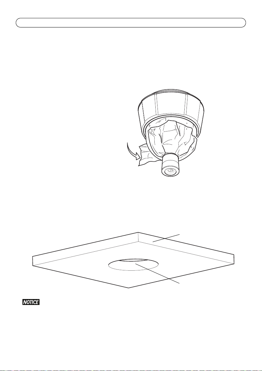
Remove the Protective Packaging
1. Loosen the 4 top cover screws and remove the top cover, see illustration on page 7.
2. Remove the protective packaging. Keep the protective packaging in case of future
transportation.
3. If installing an SD card, refer to the instructions Install an SD Card (not included), below.
4. Put the top cover back in its original position and fasten the screws cross-wise (torque 2.0 -
2.5 Nm).

AXIS P5544 Installation Guide Page 13
Mounting plate
Security wire
Install an SD Card (not included)
Installing a standard or high capacity SD card (not included), which can be used for local recording
with removable storage, is optional.
1. Loosen the 4 top cover screws and remove the top cover, see illustration on page 7.
2. Insert an SD card (not included) into the SD card slot.
3. Put the top cover back in its original position and fasten the screws cross-wise (torque 2.0 -
2.5 Nm).
To prevent corruption of recordings, the SD card should be unmounted before it is ejected.
To unmount, go to Setup > System Options > Storage > SD Card and click Unmount.
After remounting, the alignment of the lens may differ slightly and the PTZ mechanics
should be recalibrated. Go to Basic Setup or System Options > Maintenance and click Cal-
ibrate PTZ. For more information, see the User Manual available at www.axis.com
Hard ceiling mount
1. Prepare the ceiling for installation of the mounting plate, use the supplied drill template to
position the holes. Make sure to use drill bits, screws, and plugs that are appropriate for the
material.
2. Install the mounting plate.
ENGLISH
3. Loosen the 4 camera base lid screws and remove the camera base lid, see illustration on page 7.
4. Route and connect the network cable and the multi-connector cable, if applicable, to the
network camera. Be careful not to damage the cables when connecting them. Make sure the
foam gasket holes are aligned with the cable tracks and, if applicable, remove the cut-out piece
for the multi-connector cable from the foam gasket.
5. Put the camera base lid back in its original position and fasten the screws.
6. Secure the camera using the supplied safety wire.
Page 14 AXIS P5544 Installation Guide
Ceiling tile
Hole diameter
210 mm (8.3 in.)
7. Slide the unit holders on the network camera into the slots on the mounting plate and rotate
the camera unit.
8. Install the Axis midspan, see Install the Midspan, on page 17.
9. Check that the indicator LEDs on the midspan indicate the correct conditions, see the table on
page 11 for further details.
10. Remove the protective plastic film.
Drop ceiling mount
1. Remove the ceiling tile in which the drop ceiling mount is to be fitted.
2. Use the supplied template to mark the position for the 210 mm (8.3 in.) hole in the ceiling tile.
Cut around the template.
• The combined weight of the camera and ceiling mount is approximately 2.3 kg (5.1 lb.).
Check that the ceiling material is strong enough to support this weight.
• The ceiling tile should be 5 mm–60 mm (0.2 in.–2.4 in.) thick.
3. Assemble the ceiling bracket.
4. Put the ceiling bracket into the ceiling tile, see illustration on page 15.
5. Tighten the bracket arm screws using a torx 20 screwdriver head.

AXIS P5544 Installation Guide Page 15
Multi-connector cable
Network cable
Safety wire
Ceiling tile
Ceiling bracket
6. Loosen the 4 camera base lid screws and remove the camera base lid, see illustration on page 7.
7. Route and connect the network cable and the multi-connector cable, if applicable, to the
network camera. Be careful not to damage the cables when connecting them. Make sure the
foam gasket holes are aligned with the cable tracks and, if applicable, remove the cut-out piece
for the multi-connector cable from the foam gasket.
8. Put the camera base lid back in its original position and fasten the screws.
9. Secure the camera using the supplied safety wire.
ENGLISH
10. Slide the unit holders on the network camera into the slots on the mounting plate and rotate
the camera unit.
11. Install the Axis midspan, see Install the Midspan, on page 17.
12. Check that the indicator LEDs on the midspan indicate the correct conditions. See the table on
page 11 for further details.

Page 16 AXIS P5544 Installation Guide
Trim ring
Wall bracket (mounting
Safety
wire
Slots for
Screws
Torx T30
unit holders
example, sold separately)
13. Install the ceiling tile, with the camera mounted, into the ceiling.
14. Place the trim ring over the ceiling bracket and snap it into place.
15. Remove the protective plastic film.
Bracket Mount (sold separately)
The product is intended for installation in the middle of a ceiling to fully utilize the 360°
panoramic view. Installing the product close to obstacles such as walls, pillars and poles
will limit the use of the product. Using a bracket mount could limit the use of the product.
1. Install the selected bracket according to the instructions supplied
with the bracket. If drilling is required, make sure to use drill bits,
screws, and plugs that are appropriate for the material.
2. Loosen the 4 camera base lid screws and remove the camera base
lid, see illustration on page 7.
3. Route the network cable and the multi-connector cable, if
applicable, through the holes in the mounting bracket.
4. Hook the camera to the safety wire on the bracket.
5. Connect the network cable and, if applicable, the multi-connector
cable to the network camera.
6. Install the Axis midspan, see Install the Midspan, on page 17.
7. Check that the indicator LEDs on the midspan indicate the correct
conditions. See the table on page 11 for further details.
8. Put the camera base lid back in its original position.
9. Slide the unit holders on the network camera into the slots on the bracket and rotate the
camera unit.
10. Secure the network camera to the mounting bracket by fastening the 3 screws (Torx T30).

AXIS P5544 Installation Guide Page 17
Data &
Power out Data in
Port LED
AC input LED
Network camera Ethernet
AXIS T8123
11. Remove the protective plastic film.
Install the Midspan
The supplied midspan enables Axis network video products with high power consumption to receive
data and power over the same Ethernet cable. Follow these instructions to connect the midspan.
1. Connect the midspan (Data in) to the network switch using a shielded network cable (STP).
2. Connect the midspan (Data and Power Out) to the network camera, using the network cable
that has been connected to the camera.
3. Connect the midspan to an AC outlet (100 – 240 V AC), using the supplied power cable.
ENGLISH
For information on the LEDs on the midspan, see Midspan LED Indicators, on page 11.

Page 18 AXIS P5544 Installation Guide
Setup - Provides all the tools for
configuring the product to
requirements.
Help - Displays online help on
all aspects of using the camera.
Access the Axis Product
Use the software provided on the Installation and Management Software CD to assign an IP
address, set the password and access the video stream.
Calibrate the PTZ Mechanics
Calibrate the PTZ mechanics using the PTZ calibration tool, which starts automatically when you
access the product the first time or after resetting to factory default.
PTZ calibration aligns the overview mode and normal mode coordinate systems so that each point
in the overview is mapped to the correct point in the normal mode image.
PTZ calibration may be necessary for various reasons during the lifetime of the product, for example
when the top cover has been removed and remounted. To calibrate the PTZ mechanics, go to
Basic Setup or System Options > Maintenance and click Calibrate PTZ. For more information, see
the User Manual available at www.axis.com
The Live View Page
The product’s Live View page appears in your browser. Click Setup to open the product’s Setup
pages, which allow you to customize the Axis product.
The Live View page can be used in overview mode or normal mode. For more information, see the
User Manual available at www.axis.com

AXIS P5544 Installation Guide Page 19
Tip!
Visit www.axis.com/techsup to check if there is updated firmware available for your
network camera. To see the currently installed firmware version, see About in the product’s
Setup pages.
Learn more!
Visit Axis learning center www.axis.com/academy for useful trainings, webinars, tutorials
and guides.
Resetting to the Factory Default Settings
To reset the camera to the original factory default settings, use the control button and the restart
button on the side of the camera, see Hardware Overview, on page 6, as described below:
Using the control and restart buttons will reset all the parameters, including the IP address, to the
factory default settings:
1. Remove the top cover, see Remove the Protective Packaging, on page 12.
2. Press and hold the control button and the restart button at the same time.
3. Release the restart button but continue to hold down the control button.
4. Continue to hold down the control button until the status indicator color changes to amber
(this may take up to 15 seconds).
5. Release the control button.
6. When the status indicator changes to green (which may take up to 1 minute), the process is
complete and the camera has been reset. The unit now has the default IP address 192.168.0.90
7. Put the top cover back in its original position.
8. Re-assign the IP address, using one of the methods described in Assign an IP Address, on the
Installation and Management Software CD.
It is also possible to reset parameters to the original factory default settings via the web interface.
For more information, see the online help or the User Manual available at www.axis.com
Further Information
The User Manual is available from the Axis Web site at www.axis.com
ENGLISH


Mesures de sécurité
Lisez attentivement le présent Guide d'installation avant d'installer le produit Axis. Conservez le Guide
d'installation pour une utilisation ultérieure.
• Conservez le produit Axis dans un environnement sec et aéré.
• Évitez d'exposer le produit Axis aux vibrations, aux chocs ou à une forte pression. N'installez pas le
produit sur un support instable, ou des surfaces ou des murs instables ou vibrants, car cela pourrait
l'endommager.
• N'utilisez que les outils applicables pour installer le produit Axis ; une force excessive pourrait
endommager le produit.
• Pour le nettoyage, n’utilisez ni produits chimiques, ni substances caustiques ou aérosols. Utilisez un
chiffon humide pour le nettoyage.
• N’utilisez que des accessoires conformes aux caractéristiques techniques du produit. Ceux-ci peuvent
être fournis par Axis ou par un fournisseur tiers.
• Utilisez uniquement des pièces de rechange fournies ou recommandées par Axis.
• Ne tentez pas de réparer le produit vous-même, contactez Axis ou votre revendeur Axis pour toute
réparation.
• Ce produit Axis doit être utilisé conformément aux lois et réglementations locales en vigueur.
• Le produit Axis doit être installé par un professionnel qualifié. Veuillez vous conformer aux règlements
nationaux et locaux relatifs à l'installation.
Transport
• Conserver l'emballage de protection. Pour transporter le produit Axis, l'emballage de protection doit
être remis dans sa position originale.
• Pour transporter le produit Axis et éviter de l'endommager, utilisez l'emballage d'origine ou un
emballage équivalent.
FRAN
Ç
AIS
Remplacement des piles
Ce produit Axis nécessite une pile au lithium CR2032 de 3,0 V pour l'alimentation de son horloge en temps réel
interne. Dans des conditions normales d'utilisation, cette pile est censée durer au moins 5 ans. Si la pile est
faible, le fonctionnement de l'horloge en temps réel peut être affecté et entraîner sa réinitialisation à chaque
mise sous tension. Un message enregistré apparaît lorsque la pile doit être remplacée. Ne remplacez la pile qu'en
cas de nécessité !
Si la pile doit être remplacée, veuillez contacter www.axis.com/techsup pour obtenir de l’aide.
• Jetez les piles usagées conformément aux consignes du fabricant.
• Le remplacement incorrect de la pile peut entraîner un risque d'explosion.
• Remplacez la pile par une pile identique ou équivalente uniquement, en respectant les
recommandations du fabricant.

Nettoyer la bulle du dôme
• Veillez à ne pas rayer ou endommager la bulle du dôme. Ne nettoyez pas la bulle du dôme si elle
semble propre à l'œil nu et ne frottez jamais sa surface. Un nettoyage excessif peut l'endommager.
• Pour le nettoyage général de la bulle du dôme, il est recommandé d'utiliser un savon ou un détergent
neutre sans solvant, non abrasif, avec de l'eau et un chiffon doux. Rincez abondamment avec de l’eau
tiède et propre. Séchez à l'aide d'un chiffon doux pour éviter les tâches d'eau.
• N'utilisez jamais de détergents forts, d'essence, de benzène ou d'acétone, etc. et évitez toute exposition
directe aux rayons du soleil ou à des températures élevées lors du nettoyage.

AXIS P5544 Guide d'installation Page 23
AXIS P5544
Guide d'installation
Ce guide d'installation explique comment installer une Caméra réseau dôme PTZ AXIS P5544 sur
votre réseau. Pour toute autre question concernant l’utilisation du produit, reportez-vous au
Manuel de l'utilisateur, que vous trouverez sur le site www.axis.com.
Procédure d’installation
1. Vérifiez le contenu de l’emballage par rapport à la liste ci-dessous.
2. Aperçu du matériel. Reportez-vous à la page 24.
3. Installation du matériel. Reportez-vous à la page 30.
• Préparation de l'installation, reportez-vous à la page 30.
• Kit de fixation au plafond, reportez-vous à la page 31 ; kit de fixation au faux plafond,
reportez-vous à la page 32 ; support de montage (accessoire en option), reportez-vous à la
page 34.
• Pour installer l'injecteur, reportez-vous à la page 35.
4. Accéder au produit Axis. Reportez-vous à la page 36.
• Calibrer les systèmes PTZ, reportez-vous à la page 36.
• Pour la page Live View, reportez-vous à la page 36.
FRAN
Ç
AIS
Contenu de l’emballage
Élément Modèles/variantes/remarques
Caméra réseau AXIS P5544
Kit de montage Kit de fixation au plafond et au faux plafond
Tournevis Resitorx
Injecteur High PoE AXIS T8123
CD CD du logiciel d'installation et de gestion, incluant les outils d'installation et
Documentation imprimée AXIS P5544 Guide d’installation (le présent document)
Accessoires en option Accessoires de montage AXIS T91A
d'autres logiciels
Document de garantie d’Axis, gabarit de perçage, étiquettes de numéro de série
supplémentaires (x2)
Clé d’authentification AVHS
Câble multiconnexion pour la connexion d'E/S, audio et d'alimentation
Consultez le site www.axis.com pour plus d’informations sur les accessoires
disponibles

Page 24 AXIS P5544 Guide d’installation
Logement de carte SD
Voyant DEL d'état
Bouton Redémarrer
Bouton de commande
Anneau du dôme
Anneau du dôme
Bulle du dôme
Couvercle supérieur
vis (x6)
Anneau d’étanchéité
Caméra
Bulle du dôme
Lentille Panopsis
Présentation du matériel

AXIS P5544 Guide d'installation Page 25
Fixation au faux plafond
Bras de
Bras de
Plaque de fixation
support vis et
Couvercle de base de la caméra
Multiconnecteur
Crochet pour fil de sécurité
Connecteur réseau
Vis du couvercle supérieur (x4)
Couvercle supérieur
Support de rack (x3)
support (x3)
Support
vis de plaque
(x3)
Vis du couvercle de base de la caméra (x4)
Passages pour câble
Joint en mousse
rondelle (x3)
Rondelle
Fil de
Référence et numéro de série.
Le numéro de série peut être demandé
pendant l’installation.
décorative
sécurité
Fixation au plafond
FRAN
Ç
AIS

Page 26 AXIS P5544 Guide d’installation
Connecteurs
Connecteur réseau – Connecteur Ethernet RJ-45. Prend en charge la fonctionnalité Alimentation
par Ethernet Plus (PoE +), Conformité IEEE 802.3at). Utilisez l'injecteur fourni.
Conformément aux règlementations locales ou selon les conditions électriques et
environnementales dans lesquelles le produit doit être utilisé, un câble réseau blindé (STP)
peut être indiqué, voire être obligatoire. Tout câble réseau installé dans des environnements
extérieurs ou similaires doit être blindé (STP) et prévu pour cet usage spécifique. Assurezvous que l'injecteur soit correctement mis à la terre. Pour consulter les règlementations
correspondantes, reportez-vous à la Electromagnetic Compatibility (EMC).
Multiconnecteur – Borne d'extrémité pour une connexion à l'équipement externe :
• Équipement audio
• Périphériques d’entrée ou de sortie (E/S)
• Bloc d’alimentation CA/CC
Lors du branchement d'un équipement externe au produit Axis, un câble multiconnecteur est requis
afin de maintenir la classification IP51. Le câble multiconnecteur est disponible auprès de votre
revendeur Axis. Pour de plus amples informations, reportez-vous auManuel de l'utilisateur
disponible sur www.axis.com.
Logement de carte SD – Une carte SD de capacité standard ou élevée (non incluse) peut être
utilisée pour un enregistrement local avec un stockage amovible.
Pour insérer et éjecter la carte SD, il est indispensable de retirer le couvercle supérieur du produit ;
reportez-vous à la section Installation d’une carte SD (non incluse), à la page 31.
Afin de prévenir toute corruption des enregistrements, la carte SD doit être désinstallée
avant d'être éjectée. Pour la désinstaller, accédez à Configuration > Options système >
Stockage > Carte SD puis cliquez sur Désinstaller.

AXIS P5544 Guide d'installation Page 27
Puissance d'entrée CC, 24 à 34 V CC
Puissance d’entrée CA, 20 à 24 V CA
max. 17 W
max 23,6 VA
Câble multiconnecteur (vendu séparément)
Lors du branchement d'un équipement externe au produit Axis, un câble multiconnecteur (fourni
par Axis) est requis afin de maintenir la classification IP51 du produit. Le câble multiconnecteur est
disponible auprès de votre revendeur Axis.
Branchez le câble multiconnecteur au produit sur le “multi-connecteur” comme le montre
l'illustration à la page 25. Les connecteurs que comprend le câble sont les suivants:
Connecteur d'alimentation – Bloc terminal à 3 broches utilisé pour la puissance d'entrée.
Entrée audio (rose) – entrée 3,5 mm pour microphone mono ou signal mono avec entrée de haut
niveau (le canal de gauche est utilisé pour le signal stéréo).
Sortie audio (verte) – sortie audio 3,5 mm (niveau ligne) qui peut être connectée à un système de
diffusion publique (PA) ou à un haut-parleur actif avec amplificateur intégré. Il est également
possible de connecter une paire d’écouteurs. Un connecteur stéréo doit être utilisé pour la sortie
audio.
FRAN
Ç
AIS
Connecteur pour terminaux E/S – Utilisé dans le cadre d'applications telles que
la détection de mouvement, le déclenchement d'événements, l'enregistrement à
intervalles et les notifications d'alarme. En plus d'une alimentation auxiliaire et
d'une broche GND, le connecteur pour terminaux E/S assure l'interface avec :
• Sortie numérique — Permet de connecter des périphériques externes, comme des relais et
des voyants DEL. Les périphériques connectés peuvent-ils être activés par VAPIX ® Par
l'interface de programmation d'applications (API), les boutons de sortie sur la page Live
View ou une règle d'action. La sortie est considérée comme étant active (comme indiqué
dans Options système > Ports et périphériques > État du port) si le dispositif d’alarme est
activé.

Page 28 AXIS P5544 Guide d’installation
• Entrée numérique — Entrée d'alarme utilisée pour connecter des périphériques pouvant
passer d'un circuit ouvert à un circuit fermé, p. ex., les détecteurs infrarouge passifs, les
contacts de porte/fenêtre, les détecteurs de bris de verre, etc. Lorsqu’un signal est reçu,
l’état change et l’entrée devient active (ce qui est visible sous Options système > Ports et
périphériques > État du port).
Fonction Broche Remarques Spécifications
GND (Terre) 1 Mise à la terre
3.3Alimentation 3,3 V CC
Configurable
(entrée ou
sortie)
2 Peut servir à alimenter le matériel auxiliaire.
Remarque : la broche peut être utilisée uniquement
comme sortie d'alimentation.
3-6 Entrée numérique – Connectez-la à la broche de mise à la
terre pour l’activer ou laissez-la flotter (déconnectée)
pour la désactiver.
Sortie numérique – Connexion interne à la terre en cas
d’activation, flottante (déconnectée) en cas de
désactivation. En cas d’utilisation avec un relais externe,
une diode doit être connectée en parallèle à la charge, en
guise de protection contre les tensions transitoires.
1
Charge maximale =
250 mA
Entre 0 et 40 V CC
Charge max. = 100 mA
Tension maximale = +40
V CC
3.3 V max 250 mA
2
A
B

AXIS P5544 Guide d'installation Page 29
Voyants DEL de la caméra
Couleur Indication
Éteint Connexion et fonctionnement normal
Orange Stable pendant le démarrage. Clignote pendant les mises à niveau du
microprogramme.
Orange/rouge Clignote en orange/rouge en cas d’indisponibilité ou de perte de connexion réseau.
Rouge Clignote en rouge en cas d’échec de la mise à niveau du microprogramme.
Vert Reste allumé en vert sans clignoter pendant 10 secondes pendant le fonctionnement
normal après un redémarrage.
Voyants DEL de l'injecteur
Voyant DEL Couleur Indication
Indicateur Éteint Aucune caméra connectée.
Vert Stable lorsque la caméra est connectée, fonctionnement normal.
Vert, clignotant Clignote lentement en cas de surintensité ou de court-circuit sur le port.
Vert, clignotant Clignote rapidement lorsque la tension d'entrée est hors limites ou qu'il
existe d'autres erreurs internes.
Entrée CA Vert Stable lorsque l'alimentation CA est connectée.
FRAN
Ç
AIS

Page 30 AXIS P5544 Guide d’installation
Emballage de protection
Installation du Matériel
• Ne soulevez pas le produit Axis, le couvercle supérieur ou la bulle du dôme par la lentille
Panopsis.
• Veillez à ne pas rayer ou endommager la bulle du dôme. Utilisez un chiffon doux pour
nettoyer le couvercle du dôme avant de le fixer à la caméra.
Préparation de l'installation
Lisez toutes les instructions avant de préparer l'installation du produit Axis. En effet, plusieurs
étapes de cette préparation requièrent le retrait du couvercle supérieur et il serait donc plus
judicieux de les effectuer en même temps.
• Suivez les instructions décrites dans la section Enlèvement de l'emballage de protectionciaprès pour enlever l’emballage de protection, avant d’installer la caméra.
• Une carte SD de capacité standard ou élevée (non incluse) peut être utilisée pour un
enregistrement local avec un stockage amovible. Suivez les instructions décrites dans la
section Installation d’une carte SD (non incluse)ci-après pour retirer le couvercle supérieur
et installer la carte SD.
Enlèvement de l'emballage de protection
1. Desserrez les quatre vis du couvercle supérieur et retirez-le ; voir l’illustration à la page 25.
2. Retirez l’emballage de protection. Conservez l'emballage de protection en cas de transport
futur.
3. En cas d’installation d’une carte SD, reportez-vous aux instructions décrites dans la section
Installation d’une carte SD (non incluse)ci-après.
4. Replacez le couvercle supérieur dans sa position originale et serrez les vis en croix (couple 2,0 -
2,5 Nm).
 Loading...