

Page 1
BLUETOOTH ENABLED CD/MP3/WMA RECEIVER
IPOD CONTROL with INTERFACE CABLE
USB & FRONT PANEL AUX INPUT
SPECIFICATIONS:
GENERAL:
Flip Down / Detachable Face Panel
Includes Black and Silver Trim Frames
ISO DIN Chassis &ISO Wiring Connector
12 Volt DC - Negative Ground
Chassis: 178(W)x50(H)x158(D) mm
PLAYER:
CD/MP3/WMA -CDR/CDRW Player
Auto Loading/Eject
iPod Compatible
Electronic Shock Protection
(12/45 Sec. in CD / 120 Sec. in MP3)
Intro, Repeat and Random Play
MP3/WMA Files - Select Folder
Track/File or Character Search
BLUETOOTH:
Bluetooth in Phone Mode
Remote Dial Keypad
External Microphone
Phone Contacts
TUNER:
AM/FM Stereo
PLL Frequency Display
30 Station Presets (18FM/12AM)
Digital Clock
Stereo/Mono - Local/Distant
Long Range XTREME Tuner
AUDIO CONTROL:
Electronic Volume/Balance/
Treble/Bass and Fader Controls
Audio DSP Function
Subwoofer Output
4 Channel RCA Line-out
RCA Line-in
USB / AUX Input
Speaker Impedance 4-8 Ohms
5 Volt Preamp Output
High Power 40 Watts x 4 ch
DESIGNED FOR AUSTRALASIAN CONDITIONS
AX-902
Page 2
53mm
182mm
3
2
182mm
53mm
1
2
1
3
4
Release screw and
bracket
Bend these
claws, if necessary
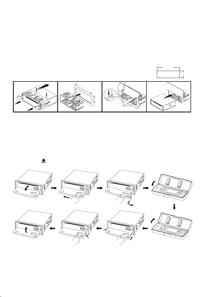
INSTALLATION
2
1
PRECAUTIONS
• Carefully choose the mounting location so normal driving is not affected.
• Avoid installing the unit where it would be subject to high temperatures (direct sunlight or hot air
from the heater) or where it would be subject to dust, dirt or excessive vibration.
• Only use the mounting hardware supplied to ensure a safe and secure installation.
• Remove the front panel before installing the unit.
Mounting angle adjustment
Adjust the mounting angle to less than 20°.
MOUNTING EXAMPLE
Installation in the dashboard
Note: Keep the release keys in the safe place as you may need them in future to remove the unit.
Detaching and attaching the front panel
The front panel of this unit can be detached in order to prevent theft.
FOLDING DOWN AND DETACHING/ATTACHING THE FRONT PANEL
Before detaching the front panel, be sure to press the PWR button (1) OFF rst.
Then press the button (16), to fully open the front panel. Detach the panel by pulling it towards
you as illustrated.
Notes:
• Do not exert unnecessary pressure on the front panel when attaching it.
• Please use the supplied case when the front panel is removed.
2
not exceed 10°
Page 3
10
7
1
2
3
4
4
4
5
5
6
6
8
9
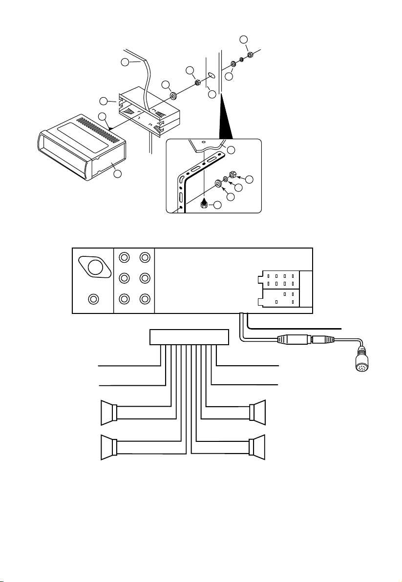
TO SUPPORT THE UNIT
SUB WOOFER
L (WHITE) R (RED)
ANTENNA
CONNECTOR
ISO CONNECTOR
L (WHITE) R (RED)
L (WHITE) R (RED)
B
A
GREY +
GREY/BLACK –
FRONT
RIGHT
SPEAKER
VIOLET +
VIOLET/BLACK –
REAR
RIGHT
SPEAKER
FRONT
LEFT
SPEAKER
REAR
LEFT
SPEAKER
+ WHITE
– WHITE/BLACK
+ GREEN
– GREEN/BLACK
ISO A/B PLUG
POWER
ANTENNA
BLUE
IGNITION SWITCH (B+)
RED
MEMORY
YELLOW
BACK UP
BLACK
GROUND (–)
LINE IN
LINE OUT
(REAR)
LINE OUT
(FRONT)
BLUETOOTH ANTENNA
CONNECT TO
EXTERNAL MICROPHONE
Dashboard
WIRE CONNECTION
1. UNIT
2. RELEASE CASE
3. DASH
4. HEX NUT
5. LOCK WASHER
6. PLAIN WASHER
7. CAR BODY
8. REAR SUPPORT STRAP
9. TAPPING SCREW
10. M5 X 15 HEX BOLT
Maintenance
FUSE REPLACEMENT
If a fuse blows, check all power connections and replace the fuse. If the fuse blows again there may be
an electronic or wiring fault. In this case, consult your nearest service centre.
Warning
Use the specied amperage fuse for each lead. Use of a higher amperage fuse may cause serious
damage and void the warranty.
3
Page 4
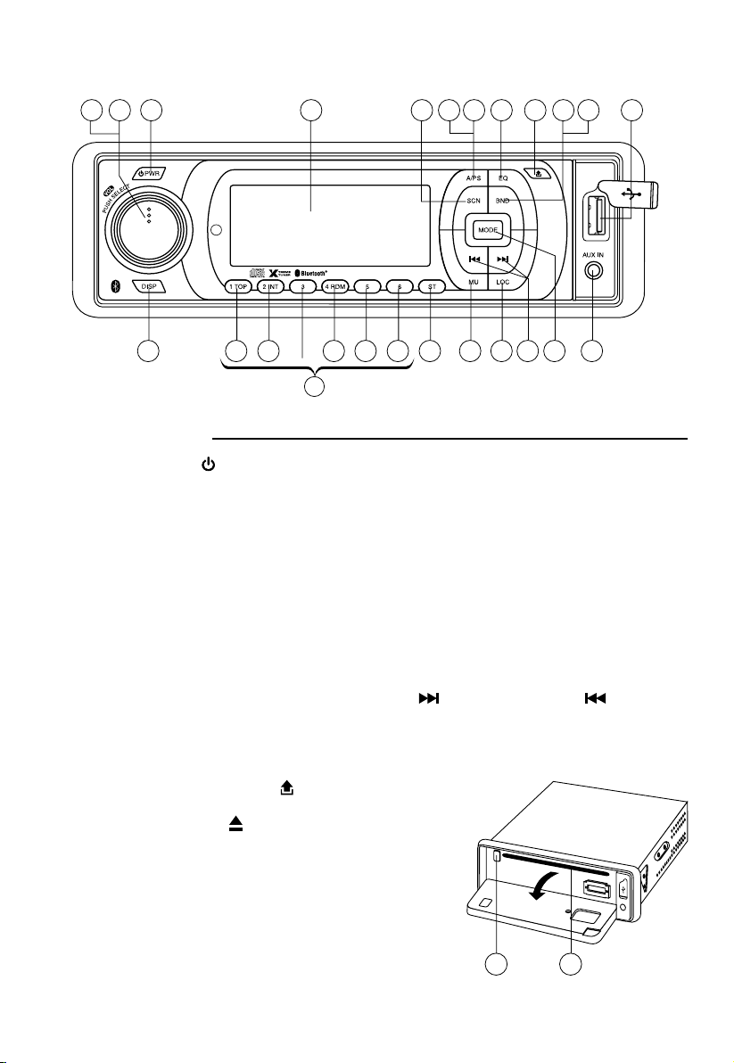
FUNCTION OF CONTROLS
MP3
(1-6)
4
1 15 1322 7 16 11 20 271423
9 19 21 23 24 25 8 5 6 261012
MP3
18 17
POSITION OF CONTROLS
(CAR STEREO)
1. POWER ON/OFF ( )
2. FUNCTION SELECT BUTTON: BASS/TREBLE/BALANCE/FADER/AUDIO DSP/
LOUDNESS/SUBWOOFER/ESP/CD MULTI/SCROLL/BEEP/STEREO/LOCAL/PAIRING
3. VOL UP/VOL DOWN FOR BASS/TREBLE/BALANCE/FADER/AUDIO DSP/
LOUDNESS/SUBWOOFER/ESP/CD MULTI/SCROLL/BEEP/STEREO/LOCAL/PAIRING
4. PRESET STATIONS (1,2,3,4,5,6)
5. MUTE BUTTON (MU)
6. LOCAL/DISTANT BUTTON (LOC)
7. EQUALIZER CONTROL (EQ)
8. STEREO/MONO BUTTON (ST)
9. DISPLAY BUTTON (DISP)
10. MODE BUTTON (MODE)
11. BAND BUTTON (BND)
12. AUTOMATIC OR MANUAL TUNING (FREQ UP
CD TRACK/SEARCH BUTTON
13. AUTO SEEK SEARCH TUNING (A/PS)
14. ‘SCAN’ AUTOMATIC TUNING CONTROL (SCN)
15. LCD DISPLAY
16. PANEL RELEASE BUTTON (
17. CD SLOT
18. CD EJECT BUTTON (
19. TOP BUTTON (TOP)
20. PAUSE BUTTON (BND)
21. INTRO BUTTON (Preview all Tracks) (INT)
22. REPEAT BUTTON (A/PS)
23. RANDOM BUTTON (RDM)
24/ 25. + 10 TRACK SEARCH DOWN/UP
26. AUX IN
27. USB PORT
OR FREQ DOWN /
)
)
4
Page 5
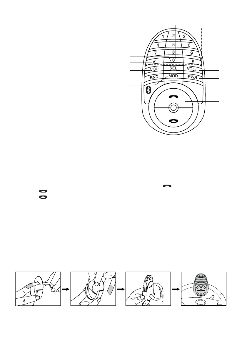
POSITION OF CONTROLS (DIAL KEYPAD)
1. POWER ON / OFF
2. ANSWER A CALL
3. VOLUME +
4. END A CALL
5. BAND
6. SELECT MENU FUNCTION
7. VOLUME -
8. MODE
9. PHONE NUMBER /
BUTTON 1-6: STATION PRESETS
10. STEREO / MONO
11. SCAN STATIONS
9
6
11
7
5
8
10
3
1
2
4
SWITCHING TO TELEPHONE MODE
1. During any operating mode, press and hold “*” to activate TELEPHONE mode. Press and hold
it again to return to previous mode.
MAKING CALLS USING THE REMOTE CONTROL
Calls can be made directly from the remote control. Before making a call, make sure that the devices
are properly paired and connected.
1. Press and hold “*” on remote control. Unit will switch to phone mode.
2. Enter the phone number via the remote control keypad and press
Press
3. Press
button to make corrections when entering numbers.
button to end call.
button to dial out.
SCAN RADIO STATION
SCAN function scans all stored frequencies and plays each for 5 seconds.
1. In Tuner mode, press ‘* ’ to start SCAN function. Press again to end.
2. When a channel is found, press and hold a memory preset key (1-6) to store in memory.
INSTALLATION OF DIAL KEY PAD
Use double sided adhesive tape (optional) to stick the remote on the dashboard or another convenient
place.
To Install on Steering Wheel:
Note: To use the remote, detach it rst from the remote holder and point directly to the head unit.
CAUTION:
Do not install the remote close to or in front of any SRS (airbag).
5
Page 6

MULT ON/OFFMULT
DSP
SEL
2 sec.
SEL
SEL
DSP
SEL
2 sec.
POP --- ROCK --- CLASSIC --- FLAT --- DSP OFF
VOL
LOUD ON/OFF
DSP
SEL
2 sec.
SEL
LOUD
SEL
LOUD
VOL
WOOF ON/OFF
WOOF
VOL
DSP
SEL
2 sec.
SEL
SEL
LOUD
WOOF
VOL
ESP
SEL
ESP 10/40
VOL
DSP
SEL
2 sec.
SEL
SEL
LOUD
WOOF
ESP
SEL
DSP
SEL
2 sec.
POP --- ROCK --- CLASSIC --- FLAT --- DSP OFF
VOL
LOUD ON/OFF
DSP
SEL
2 sec.
SEL
LOUD
VOL
GENERAL CONTROLS
VOLVOL
VOLVOL
VOLVOL
VOLVOL
VOLVOLorVOLVOL
1 3
2
4
2
5
2
6
2 2
DSP
SEL
2 sec.
POP --- ROCK --- CLASSIC --- FLAT --- DSP OFF
VOL
DSP
SEL
2 sec.
SEL
DSP
SEL
2 sec.
POP --- ROCK --- CLASSIC --- FLAT --- DSP OFF
VOL
LOUD ON/OFF
DSP
SEL
2 sec.
SEL
LOUD
SEL
LOUD
VOL
WOOF ON/OFF
WOOF
VOL
DSP
SEL
2 sec.
SEL
DSP
SEL
2 sec.
POP --- ROCK --- CLASSIC --- FLAT --- DSP OFF
VOL
LOUD ON/OFF
DSP
SEL
2 sec.
SEL
LOUD
SEL
LOUD
VOL
WOOF ON/OFF
WOOF
VOL
DSP
SEL
2 sec.
SEL
SEL
LOUD
WOOF
ESP
SEL
ESP 10/40
VOL
1. POWER ON/OFF
Press this key to switch the unit on and off.
Also, this unit can be turned on by pressing any key.
2. SELECT
3. VOLUME UP/DOWN
Turn the VOL knob Right or Left (3) to adjust VOL/BASS/TREB/BAL/FAD. To select other functions,
continue to press the VOL knob until the desired function is shown on the display. See Figure 1.
Fig. 1 Selection of sound control functions
1. VOL 2. SEL 3. BAS 4. TRE 5. BAL 6. FAD
or
Turn the VOL knob
be used to adjust the BASS, TREBLE, BALANCE and FADER.
AUDIO DSP CONTROLS (2)
Press the SEL button for more than 2 seconds to select Digital Sound Processor mode.
LOUDNESS CONTROLS (2)
Press the SEL button for more than 2 seconds to activate Loudness function.
to increase or decrease the volume levels.These buttons can also
LOUD ON/OFF mode is selected by
or
. The bass and treble response will boost.
SUBWOOFER MODE (2)
Press the SEL button for more than 2 seconds to activate the Subwoofer mode as shown below.
ESP MODE (2)
Press SEL button for more than 2 sec. to activate Electronic Shock Protection mode as 12 sec. or 45
sec.
MULTI CD SECTION MODE (2)
Press the SEL button for more than 2 seconds to activate this function.
CD MULTI ON/OFF mode is selected by
CD.
CD MULTI OFF: Read rst section only.
6
key. CD MULTI ON: Read multi section
Page 7

MULT ON/OFFMULT
DSP
SEL
2 sec.
SEL
SEL
DSP
SEL
2 sec.
POP --- ROCK --- CLASSIC --- FLAT --- DSP OFF
VOL
LOUD ON/OFF
DSP
SEL
2 sec.
SEL
LOUD
SEL
LOUD
VOL
WOOF ON/OFF
WOOF
VOL
DSP
SEL
2 sec.
SEL
SEL
LOUD
WOOF
VOL
LOCAL
SEL
DX/LOCAL
VOL
STEREO
SEL
STEREO ON/OFF
VOL
BEEP
SEL
BEEP ON/OFF
VOL
SCROLL
SEL
SCROLL 1/2
VOL
ESP
SEL
ESP 10/40
VOL
DSP
SEL
2 sec.
SEL
SEL
LOUD
WOOF
ESP
SEL
MULT
SEL
DSP
SEL
2 sec.
SEL
SEL
LOUD
WOOF
ESP
SEL
SCROLL
SEL
MULT
SEL
DSP
SEL
2 sec.
SEL
SEL
LOUD
WOOF
ESP
SEL
BEEP
SEL
SCROLL
SEL
MULT
SEL
DSP
SEL
2 sec.
SEL
SEL
LOUD
WOOF
ESP
SEL
STEREO
SEL
BEEP
SEL
SCROLL
SEL
MULT
SEL
DSP
SEL
2 sec.
SEL
SEL
LOUD
WOOF
ESP
SEL
MULT ON/OFFMULT
DSP
SEL
2 sec.
SEL
SEL
DSP
SEL
2 sec.
POP --- ROCK --- CLASSIC --- FLAT --- DSP OFF
VOL
LOUD ON/OFF
DSP
SEL
2 sec.
SEL
LOUD
SEL
LOUD
VOL
WOOF ON/OFF
WOOF
VOL
DSP
SEL
2 sec.
SEL
SEL
LOUD
WOOF
VOL
STEREO
SEL
STEREO ON/OFF
VOL
BEEP
SEL
BEEP ON/OFF
VOL
SCROLL
SEL
SCROLL 1/2
VOL
ESP
SEL
ESP 10/40
VOL
DSP
SEL
2 sec.
SEL
SEL
LOUD
WOOF
ESP
SEL
MULT
SEL
DSP
SEL
2 sec.
SEL
SEL
LOUD
WOOF
ESP
SEL
SCROLL
SEL
MULT
SEL
DSP
SEL
2 sec.
SEL
SEL
LOUD
WOOF
ESP
SEL
BEEP
SEL
SCROLL
SEL
MULT
SEL
DSP
SEL
2 sec.
SEL
SEL
LOUD
WOOF
ESP
SEL
SCROLL MODE
MULT ON/OFFMULT
DSP
SEL
2 sec.
SEL
SEL
DSP
SEL
2 sec.
POP --- ROCK --- CLASSIC --- FLAT --- DSP OFF
VOL
LOUD ON/OFF
DSP
SEL
2 sec.
SEL
LOUD
SEL
LOUD
VOL
WOOF ON/OFF
WOOF
VOL
DSP
SEL
2 sec.
SEL
SEL
LOUD
WOOF
VOL
BEEP
SEL
BEEP ON/OFF
VOL
SCROLL
SEL
SCROLL 1/2
VOL
ESP
SEL
ESP 10/40
VOL
DSP
SEL
2 sec.
SEL
SEL
LOUD
WOOF
ESP
SEL
MULT
SEL
DSP
SEL
2 sec.
SEL
SEL
LOUD
WOOF
ESP
SEL
SCROLL
SEL
MULT
SEL
DSP
SEL
2 sec.
SEL
SEL
LOUD
WOOF
ESP
SEL
MULT ON/OFFMULT
DSP
SEL
2 sec.
SEL
SEL
DSP
SEL
2 sec.
POP --- ROCK --- CLASSIC --- FLAT --- DSP OFF
VOL
LOUD ON/OFF
DSP
SEL
2 sec.
SEL
LOUD
SEL
LOUD
VOL
WOOF ON/OFF
WOOF
VOL
DSP
SEL
2 sec.
SEL
SEL
LOUD
WOOF
VOL
LOCAL
SEL
DX/LOCAL
VOL
STEREO
SEL
STEREO ON/OFF
VOL
BEEP
SEL
BEEP ON/OFF
VOL
SCROLL
SEL
SCROLL 1/2
VOL
ESP
SEL
ESP 10/40
VOL
DSP
SEL
2 sec.
SEL
SEL
LOUD
WOOF
ESP
SEL
MULT
SEL
DSP
SEL
2 sec.
SEL
SEL
LOUD
WOOF
ESP
SEL
SCROLL
SEL
MULT
SEL
DSP
SEL
2 sec.
SEL
SEL
LOUD
WOOF
ESP
SEL
BEEP
SEL
SCROLL
SEL
MULT
SEL
DSP
SEL
2 sec.
SEL
SEL
LOUD
WOOF
ESP
SEL
STEREO
SEL
BEEP
SEL
SCROLL
SEL
MULT
SEL
DSP
SEL
2 sec.
SEL
SEL
LOUD
WOOF
ESP
SEL
LOCAL
SEL
PAIRING
SEL SEL
STEREO
SEL
BEEP
SEL
SCROLL
SEL
MULT
SEL
DSP
SEL
2 sec.
SEL
SEL
LOUD
WOOF
ESP
SEL
MULT ON/OFFMULT
DSP
SEL
2 sec.
SEL
SEL
DSP
SEL
2 sec.
POP --- ROCK --- CLASSIC --- FLAT --- DSP OFF
VOL
LOUD ON/OFF
DSP
SEL
2 sec.
SEL
LOUD
SEL
LOUD
VOL
WOOF ON/OFF
WOOF
VOL
DSP
SEL
2 sec.
SEL
SEL
LOUD
WOOF
VOL
SCROLL
SEL
SCROLL 1/2
VOL
ESP
SEL
ESP 10/40
VOL
DSP
SEL
2 sec.
SEL
SEL
LOUD
WOOF
ESP
SEL
MULT
SEL
DSP
SEL
2 sec.
SEL
SEL
LOUD
WOOF
ESP
SEL
Press the SEL button for more than 2 seconds to activate this mode.
SCROLL 1: Unit displays song details but no text scrolling.
SCROLL 2: Unit displays song details and scrolls the text information to the left.
BEEP MODE (2)
Press the SEL button for more than 2 seconds to activate Beep functions.
BEEP ON: BEEP sound can be heard when any button is pressed.
STEREO/MONO (2)
Press the SEL button for more than 2 seconds to activate these function.
When FM signal is weak or distorted, reception may improve by selecting MONO.
LOCAL/DX (2)
Press the SEL button for more than 2 seconds to activate this function.
“Local” position in areas with strong signal will cause radio to stop at only strong stations. During
manual tuning (LOC appears). Select Distant position in areas with weak signal.
PAIRING MODE (2)
Press the SEL button for more than 2 seconds to activate Pairing for Bluetooth functions. (Please refer
to HOW TO PERFORM PAIRING on page 11)
4. PRESET STATIONS
Six numbered preset button store and recall stations for each band.
Storing a station:
1. 1. Select a band (if needed)
2. Select a station
3. Hold a preset button longer than one second. Preset station number appears in the display when
station is saved.
Recall a station:
1. Select band (if needed)
2. Press a preset button for less than one second to select stored station.
5. MUTE BUTTON
Press this button to mute the sound. Press again to return to previous volume level.
7
Page 8

6. LOCAL/DISTANT BUTTON
VOLVOL
VOLVOL
Press Local/Distant LOC button for listening to weak stations. “LOCAL” indicator will appear on the
display. Press this button again (Distant mode) for normal operation.
7. EQUALIZER CONTROL
Press EQ to select between Off/Pop/Rock/Classic/Flat equalizer modes.
8. STEREO/MONO (ST)
When an FM station is weak or distorted, audio may improve by selecting MONO.
9. DISPLAY BUTTON (Set the Clock)
Selects radio frequency or clock display.
To set the clock:
1. With clock display selected, hold down DISP button until clock display starts ashing.
2. Rotate
to change minutes,
to change hours.
3. Press DISP button to start clock.
10. MODE BUTTON
By pressing this key, user can select. AUX/TUNER/CD-MP3/USB mode.
11. BAND SELECTOR SWITCH
Push this switch to select the desired band.
12. AUTOMATIC OR MANUAL TUNING (FREQ UP
OR FREQ DOWN )
(A) RADIO MODE
When pressed for less than 1 second, these keys operate as manual tuning mode.
When pressed longer than 1 second they operate as SEEK tuning mode.
If the keys are not pressed for 3 seconds, they will return to SEEK mode again.
(B) CD/MP3/WMA PLAYER MODE
When pressed for less than 1 second, they will operate as TRACK UP or TRACK DOWN mode.
When pressed longer than 1 second they will operate as CUE or REVIEW mode.
13. AUTOMATICALLY STORE STATIONS
Select six strong stations and store them in current band.
1. Select a band (if needed)
2. Hold
A/PS button for more than three seconds. The new stations replace stations already stored in
that band.
Preset Scan
Scan stations stored in current band
1. Select a band (if needed)
2. Touch A/PS for more than one second but less than three seconds. Radio pauses for ve seconds at
each station. Touch A/PS again to stop scanning when desired station is reached.
14.‘SCAN’ AUTOMATIC TUNING CONTROL (SCN)
This key operates as RADIO SCAN. The function is similar to normal SEARCH but pauses at each
stored station for 5 seconds.
On the Remote Control: Press “*” to start SCAN function. Press it again to end. When a channel is
found, press and hold a preset key (1-6) to store in memory.
15. LCD DISPLAY
The Liquid Crystal Display will display the current state of the unit.
16. OPEN THE FRONT PANEL
Press
button and the front panel will open.
8
Page 9

CD/MP3/WMA CONTROL
Inserting the CD
Carefully slide the CD through the CD slot into the mechanism. The CD starts playing automatically.
TRACK/SEARCH BUTTON
FORWARD AND REVERSE TRACK SEARCH
Press and release to advance to next track or to return to the beginning of the current track (track number
will be displayed.) Press and hold to fast forward or reverse . Play will begin at the point when
you release the button.
17. CD SLOT
18. CD EJECT BUTTON
Press the EJECT
19. TOP BUTTON
Press to play rst song of current folder.
20. PAUSE BUTTON
Press BND button to pause CD playback. Press again to resume.
21. INTRO BUTTON (Preview all Tracks) ‘INT’
Press this button to display ‘INT ON’. The rst few seconds of each track on the disc will play. Press
again to stop intro and listen to selected track.
22. REPEAT BUTTON ‘RPT’
When A/PS button is pressed, ‘RPT ON’ is displayed and the selected track will repeat continually
until the Track repeat mode is cancelled by pressing ‘A/PS’ button again.
23. RANDOM BUTTON ‘RDM’
When this button is pressed, ‘RDM ON’ is displayed and each track on the disc will play in random
order instead of normal sequence. To cancel RANDOM mode, press ‘RDM’ button (23) again.
24, 25. 10 TRACK UP/DOWN SELECT: (In case of MP3/WMA les)
M5: 10 Track down / M6: 10 Track up
button to remove the CD. The receiver will automatically switch to radio mode.
HOW TO SELECT MP3/WMA FILES
1. Searching Track:
• Press and hold “A/PS”. Search track is activated.
• Press “VOL” knob. The rst digit will ash.
• Rotate “VOL knob to right or left”. Select rst digit desired.
• Press “VOL” knob. The rst digit is then xed and second digit will ash.
• Rotate “VOL knob to right or left”. Select 2nd and 3rd respectively.
• The song selected will then automatically play.
2. Searching Character:
• Press and hold “A/PS”. Press “A/PS” again to activate character search mode.
• Press “VOL” knob. “A” character is displayed.
• Rotate “VOL knob to right or left” to select the desired letter.
• Press “VOL” knob for longer than 2 seconds. The song with this character will display.
• Rotate “VOL knob to right or left” to select the desired song.
• Press “VOL” knob again. The selected song will now play.
3. Searching File Name:
• Press and hold “A/PS”. Press “A/PS” again, then directory search is activated.
• Press “VOL” knob. The rst directory is displayed.
9
Page 10

• Rotate “VOL knob to right or left” to select the desired directory.
• Press “VOL” knob again. The directory is xed and the rst le name is displayed.
• Rotary “VOL knob to right or left” to select the required le.
• Press “VOL” knob again. The selected song will now play.
Connecting to a Portable MP3 Player
26. FRONT AUX IN
This unit is compatible with the audio output of iPod and other MP3 Players. The front “AUX IN”
input jack allows easy connection of Portable Media such as iPod or other MP3 Players via the USB or
3.5mm Stereo Jack.
More AUX input:
Additional auxiliary RCA input jacks on the back of the unit can be used to connect other external audio
sources such as a DVD player, Game Console and other portable audio device.
27. USB PORT
Use a USB cable to connect your portable MP3 Player.
Connecting iPOD
Connect iPOD portable devices and play songs through the car stereo. Not all iPOD features may be supported.
How to connect iPOD
Playing Songs in iPOD
Tunes in iPOD can be played once the cable is properly connected.
1. Press
MODE until USB-DRIV > I-POD shows in the display.
2. Press and hold
3. Rotate
4. Press
If you are aware of iPOD operating functions, the way to use this car stereo feature is basically the same. Take
note of the equivalent key function below.
A/PS.
VOL to select PLAYLIST - ARTIST - ALBUM - GENRE - SONG - COMPOSER - TRACK.
VOL.
Car Stereo iPOD Function
Rotate VOL knob Rotate CLICK WHEEL Up/down category/le browsing
Press VOL knob Press SELECT button Selecting a category/Play song
Car Stereo and iPOD equivalent key function
Note:
Please refer to your iPOD user manual for operating instructions.
Press A/PS to go back to Main Menu.
10
Page 11

HOW TO USE BLUETOOTH IN YOUR CAR AUDIO
How to Perform Pairing
Before dialling out from the car stereo, PAIRING must rst be performed.
Pairing is a procedure used to connect 2 Bluetooth devices together.
1. Press and hold
2. Press
3. Press and hold
4. Turn on the Bluetooth feature of your mobile phone. Perform “Add Bluetooth device” from your mobile
5. The LCD will display
Note:
• If “DISCONN” shows instead of “PAIRING”, it means the head unit currently is paired with another
•
• Refer to your cellular user manual for the proper procedures of pairing Bluetooth devices.
Switching to Telephone Mode
1. During any operation mode, press and hold “*” to activate TELEPHONE mode.
Press and hold it again to return to previous mode.
Making Calls Using the Remote Control
Before making calls directly from the remote control ensure that the devices are properly paired and connected.
1. Press and hold “*” on remote control. Unit will switch to phone mode.
2. Enter the phone number via the remote control keypad and press
Press
3. Press
Audio Streaming
If your phone is “A2DP” format compatible, then you can play music in your mobile and the sound will
be transferred to the vehicle’s sound system.
1. Mobile phone and the head unit must be properly paired and connected.
2. Play the music through your mobile music player software.
3. Continuously press
SEL button repeatedly until “PAIRING” displays.
phone. The mobile will search for any Bluetooth devices within the range. Select “CAR BLUETOOTH”
and enter Passkey: “0000” to connect to the car audio.
device. Press and hold SEL button to disconnect the connection and perform steps above again.
“CAR BLUETOOTH” is the Bluetooth device name of the car stereo.
unit.
SEL button for 2 seconds.
SEL button to engage pairing mode. “PAIRING” blinks on the display.
“PAIRED” when successful.
button to dial out.
bbutton to make corrections when entering numbers.
bbutton to end call.
MODE until “BT-PLAY” appears in the display. The sound will transfer to the head
Answering / Hanging Up
To answer a call, press the button on the remote control.
Once you have nished your conversation, press the button to hang up.
Calls (Outgoing, Incoming)
The unit stores all the incoming and outgoing calls. Use this feature to check the numbers and make calls.
“OUT NUM” – outgoing calls made through the remote control.
1. Press and hold (*) then press and hold
2. Press and hold
3. Rotate volume knob to search for entries and press
“IN NUM” – incoming calls received.
1. Press and hold (*) then press and hold
2. Press
3. Press and hold
4. Rotate volume knob to search for entries and press
SEL button repeatedly until “IN NUM” displays.
SEL button again.
SEL button again.
SEL button for 2 seconds. “OUT NUM” displays.
to call.
SEL button for 2 seconds.
to call.
11
Page 12

Adding Contacts
RESET
The unit can save contact telephone numbers for quick access.
1. Press and hold (*) then press and hold
2. Continuously press
3. Press and hold
SEL button until “ADD NUM” displays.
SEL button again.
SEL button for 2 seconds.
4. Using the volume knob, enter the name of the contact. Press
tered.
5. Enter the phone number. Press
6. Press and hold
SEL button to save entry
SEL button to save each number entered.
Finding Contacts
After adding contacts, you can use this feature to nd them.
1. Press and hold (*) then press and hold
2. Continuously press
3. Press and hold
SEL button until “FIND NUM” displays.
SEL button again.
SEL button for 2 seconds.
4. Using volume knob, select the name of the contact and press
SEL button to save each character en-
to call.
Deleting Contacts
1. Press and hold (*) then press and hold
2. Press
3. Press and hold
4. Rotate
5. Press and hold “
SEL button repeatedly until “FIND NUM” displays.
SEL button again.
VOL knob until the name of the contact you want to delete displays.
” for 2 seconds to delete contact.
SEL button for 2 seconds.
How to Set Incoming Call Melody
1. Press and hold
2. Press
SEL button repeatedly until “MELODY” displays.
3. Rotate
(*) then press and hold SEL button for 2 seconds.
VOL knob to the desired melody.
How to Set Incoming Call Ring Volum
1. Press and hold (*) then press and hold
2. Continuously press
3. Rotate
VOL knob to the desired level.
SEL button until “RING” displays.
SEL button for 2 seconds.
How to Set Conversation Volume
1. Press and hold (*) then press and hold
2. Continuously press
3. Rotate
VOL knob to the desired level.
SEL button until “TEL” displays.
SEL button for 2 seconds.
Disconnect Paired Devices
You can disconnect to an already paired Bluetooth device from your car stereo.
1. Press and hold (*) then press and hold
2. Continuously press
3. Press and hold
SEL button until “DISCONN” displays.
SEL button again to disconnect.
SEL button for 2 seconds.
RESET
A reset button is placed on the front housing.
The reset button is to be activated for the following reason:
Initial installation of the unit after all wiring is complete.
No function buttons operate.
Error symbol on the display.
12
Page 13

CAUTION & MAINTENANCE
The detachable panel AM/FM car radio with CD player is an example of superior design and
craftsmanship. The following suggestions will help you care for the product and experience many
years of enjoyment.
1. Do not touch the contacts on the front panel or the unit body.
2. The product can only operate on 12V-14V DC power supply, negative ground.
3. Avoid exposing your product to high temperature and humidity.
4. Handle the product with care. Dropping it can damage circuit boards and cause the product to
malfunction.
5. Modifying or tampering with internal components can cause damage and may invalidate the
warranty.
6. Always remove the CD from the unit when it has nished playing or not being used.
TROUBLESHOOTING GUIDE
SYMPTOM
No sound or power
No sound in one
channel
POSSIBLE CAUSE
Speaker cord disconnected.
Bad power connection
Blown fuse.
Mis-adjusted balance
control
Damaged speaker wire
or speaker
SOLUTION
Check to see that all the power and
speaker leads are securely connected.
Replace fuse with same amperage.
Check balance control.
Reverse left and right channel
speaker leads If no sound from other
side, check or replace speaker wire.
If no sound from both sides, replace
both speakers.
Poor FM reception
CD sound quality
poor
Insensitive or defective
antenna.
Disc reading malfunction.
Disc may be damaged or dirty.
Lens may need cleaning.
Replace with a good sensitivity
antenna.
Try a different disc.
Clean Disc with a soft cloth.
Insert a quality lens cleaning disc.
ERROR CODE
ERROR CD USB
ERROR 1 SLED INITIALIZED
ERROR 2 FE BIAS CONTROL
ERROR 3 FOCUS SERVO OFFSET / TRACKING SERVO
OFFSET / OFFSET CONTROL
ERROR 4 FOCUS SEARCH / CLV KICK
ERROR 5 TOC READ
ERROR 6 RECOVERY
ERROR 7 MP3 NO FILE
ERROR 8 MP3 READ ERROR
ERROR 12 TMC51F DATA ERROR
ERROR 13 TMC51F COMMUNICATION ERROR
ERROR 14 MS BOOT ERROR
ERROR 15 TMC51F NO READ ERROR
ERROR 16 NO FILE ERROR
13
Page 14

TECHNICAL SPECIFICATIONS
CD/MP3/WMA PLAYER SECTION
Signal to Noise Ratio > 60 dB
Channel Separation > 50 dB (1kHz)
Frequency Response 20Hz - 20 kHz
TUNER (FM)
Frequency range 87.5 - 108 MHz
Intermediate frequency 10.7 MHz
Sensitivity 2.8 µV
Stereo separation 30 dB
Signal to noise ratio 50 dB
Channel step 100 kHz
TUNER (AM)
Frequency Range 522 - 1710 KHz
Intermediate Frequency 10.71 MHz
Usable Sensitivity 32 dBμV
GENERAL
Power Supply 12V DC (10.8 - 15.6V allowable)
Speaker impedance 4 or 8 Ohm
Output power 40W x 4CH
SUB OUT
Frequency Response 20 Hz - 50 Hz
Sensitivity 300 mV
Max Output 4V
RCA OUT
Frequency Response 20 Hz - 20 KHz
Sensitivity 200 mV
Output Impedance 2 K
Max Output 5 Volt (max.)
RCA IN
Frequency Response 20 Hz - 20 KHz
Sensitivity 775 mV
Input Impedance 20 K
USB Operation and Compatibility, USB 1.1 , USB 2.0 Full Speed.
BLUETOOTH
Version V1.2
Range 5M
Audio Stereo Audio Streaming
DIMENSIONS
Chassis 178(W)x50(H)x158(D) mm
7(W)x2(H)x6.2(D) inch
Nose piece 188(W)x58(H)x20(D) mm
7.4(W)x2.3(H)x0.8(D) inch
Note: This unit has been designed to be compatible with the latest MP3 and USB technology. There is a wide variety
of memory cards, USB sticks and software formats available. However not all may be compatible with this product.
Specication and design is subject to improvement and modication without notice.
14
Page 15

WARRANTY
Congratulations on your purchase of a quality Mobile Audio System! You’re joining thousands
of satised customers who enjoy & experience the benets of the products we distribute. In the unlikely
event that some technical difculty arises with your purchase, be assured that we are most anxious to
see that the problem is quickly rectied to your satisfaction. Please familiarise yourself with the following
simple conditions of our warranty.
This warranty covers faults through component failure of the product to operate in accordance with
published specications. Product failure as a result of unreasonable environmental conditions, accident,
misuse, improper installation, unauthorised repair, vehicle electrical or wiring faults or neglect etc, will not
be covered by this warranty. Removal and installation costs, if any, would be paid by the owner as well
as any freight or postage costs of transporting the product to AudioXtra. AudioXtra shall not be liable or
responsible for any loss of use of this product or any form of consequential loss.
CONSUMER WARRANTY
This product is warranted by AudioXtra International Pty Ltd to be free from defects in materials and workmanship under NORMAL USE for a period of TWENTY FOUR MONTHS from the date of purchase.
WITHIN 30 DAYS OF PURCHASE DATE: Please return the unit for replacement to our National Service
Centre or the Retailer from where you made the purchase. All accessories must be included. Proof of
purchase date must accompany the product.
AFTER 30 DAYS OF PURCHASE DATE: Warranty repair and service is carried out by our National
Service Centre. Repair and service will be carried out at no cost to the owner if proof of ownership and
the date of purchase can be veried to the satisfaction of the authorised centre concerned with this
repair. This proof should take the form of either:
a) The warranty card accompanying this product, stamped and dated by the dealer.
b) A Tax Invoice or Receipt showing full details of original vendor, purchaser, model number and
serial number.
COMMERCIAL WARRANTY: A product used in or associated with a commercial application will
carry a limited SIX MONTH warranty. An abnormal commercial application is one where usage, dust,
vibration, heat/cold and other environmental conditions exist at an extreme level.
Please complete details below in the event of warranty service being required.
Purchaser’s Name:
Purchaser’s Address:
Model Number:
AX-902
Serial Number:
Dealer Name: Date of Purchased: / /
Dealer Address:
Invoice/Sales Docket no:
General Hints :
To expedite service and prompt return of the equipment, please:
a) Clearly describe the fault in detail
b) Safety and security pack the unit for transport
c) Include your return address
d) Provide proof of purchase date as outlined above
National Service Centre:
10 STODDART ROAD, PROSPECT, SYDNEY NSW 2148 Australia
Telephone: (02) 9631 4199 Fax: (02) 9636 1204 email: service@audioxtra.com.au
www.audioxtra.com.au
Page 16

 Loading...