

Page 1

© Axis Communications AB
Page 2

2
Add AXIS A1601s to AXIS Camera Station 5
Upgrading firmware of the AXIS A1601 7
Time setup of the AXIS A1601 7
Adding and editing identification profiles 10
PIN length configurations 12
Adding and editing card formats 13
Add door 15
Door name and controller selection 15
Cloning a configuration 16
Door settings 17
Door monitor settings 18
Emergency input settings 19
Reader settings 20
REX settings 21
Supervised inputs 23
PIN chart 24
Add zone 26
Import cardholder data 30
Exporting cardholder data 32
Page 3

3
Restoring from last import point 32
Adding a cardholder group 33
Adding and editing a cardholder 35
Adding and editing a card credential 36
Adding and editing a PIN credential 38
Adding and editing access rules 38
Edit door in access management 39
Edit zone in access management 40
Sending actions to doors and zones from the access management dashboard 40
Connect a split view or camera view to a door 41
Door plugin view 42
Data search (Access Control Event log with video link) 43
Hardware 44
Access management 44
Page 4

4
•
•
•
Page 5

5
In this chapter we will cover adding door controllers and doing the basic setup of AXIS Camera
Station Secure Entry.
Add AXIS A1601s to AXIS Camera Station
Start the AXIS Camera Station Client if not already started.
From AXIS Camera Station version 5.35 AXIS A1601 Network Door Controllers can be added as
a device. Add AXIS A1601s to the system just as you are used to doing with your cameras.
Page 6

6
To change the name of your door controller: Go to Configuration → Devices → Other Devices
and edit the system names. Setting a name for your door controller can also be done when
adding the device.
Page 7

7
Upgrading firmware of the AXIS A1601
Go to Configuration → Devices → Management and update the Firmware of the added A1601s
Time setup of the AXIS A1601
Set the correct Date and Time for all your controllers.
Factory defaulting when doing a firmware upgrade is required
when going from the Active firmware track to the Secure
Entry firmware track
Page 8

8
Since it is important in an access control setup that all devices and the server is in sync when it
comes to time, specifying an NTP -server for time synchronization or having the AXIS Camera
Station Server act as an NTP server is strongly recommended. You can setup the Server to act
as an NTP under Configuration→Server→Settings
Page 9

9
An identification profile is a profile applied to one or many doors that defines how a cardholder’s
access attempt is validated through the sides of a door. The identification type needs to be
associated with a door to have an effect on the system.
Identification profiles are configured under Configuration → Access control → Identification
profiles. There are four system default Identification profiles available as reference that you can
edit to achieve the system functionality you need, or you can create your own identification
profiles from scratch.
The solution contains identification profiles by default. If you have no
special needs that you know of, you can skip this section and come back
to it later if there is a need.
Page 10

10
Adding and editing identification profiles
When creating an identification profile, you combine the means of identification such as Card and
PIN with a schedule as to when the created identification type (for instance card + pin) should be
active on the specific side of the door or doors that will later have this identification profile applied
to it.
You can combine many identification types on different schedules to configure exactly how your
means of identification should be applied on, for instance entrance doors.
Clicking on the small calendar icon to the far right of the identification profile’s respective door
side will give you a visual calendar representation of the identification profile applied to that side
of the door. Remember, you need to add an identification type for both Side A and B
Page 11

11
Let’s say you have a reader (or all readers) in the system providing you with a card number that
is not what is expected/printed on the card. A card format can adjust this inside each door
controller so that the validation data are matched correctly with the credentials connected to the
cardholders in the system.
The solution contains card formats by default. If you have no special
needs that you know of, you can skip this section and come back to it
later if there is a need.
Page 12

12
Configuring Card formats are done under Configuration → Access control → Card formats and
PIN. What is done here is setting up the translation table between the data that the door
controllers in the system receive from their connected card readers and the wanted data that
access validations are based on.
The system has a few predefined commonly used card formats that you can use as they are or
use as reference when creating custom card formats. Each card format has a different set of data
parameters, field maps, for how the information stored on the card is organized. By defining a
card format you tell the system how to interpret the information that the controller gets from the
reader. For information about which card formats the reader supports, see the manufacturer’s
instructions. In this view you also have the possiblity to adjust your systems PIN code length.
Settings done in this section are applied generally on all readers in the system unless they have
been changed to local settings with deviations from the general settings.
PIN length configurations
Press the PIN length button to adjust the wanted PIN lengths in the system.
Page 13

13
Here you can adjust your systems minimum pin length as well as maximum pin length. If you
have a difference between the minimum and maximum values, you need to set an end of pin
character for the system’s door controllers to know that a cardholder with a shorter PIN is finished
inputting the PIN at the card reader.
Adding and editing card formats
Give your new card format a name.
Define the bit length of the format enabling the systems door controllers to use this format when
card data with 32 bits are received from the card reader. Check the boxes if you want to invert bit
or byte order of the entire data received.
Inverting bit order
Inverting the bit order of the incoming data is basically switching the reading of the
bits (ones or zeroes from reading from left to right to reading from right to left)
19 275 = 0100 1011 0100 1011 → 1101 0010 1101 0010 = 53 970
→ Read from left Read from right←
Inverting byte order
Firstly, we must establish that one byte equals eight bits (ones or zeroes). Same as for
inverting the bit order we switch the reading of bytes from left to right to from right to left.
64 332 = 1111 1011 0100 1100 = FB4C → 4CFB = 0100 1100 1111 1011 = 19 707
F B 4 C
Page 14

14
Choose if card number and/or facility code should be data fields that are active in your card
format and set the bit ranges for the respective fields to get the field representation out from the
binary card data.
Choose what output format you want from the respective field for your system’s credential
validation. If it should be decimal (Int) or hexadecimal output.
Choose the bit order of the data field.
Page 15

15
To configure the doors and zones in the system you need to go to Configuration → Access
control → Doors and zones
Add door
Add a door by pressing the “+ Add door”-button.
Door name and controller selection
Give the door a name and connect it to a door controller you have configured in the system. Click
“Next”.
Page 16

16
Cloning a configuration
If you want to copy a door configuration from a previously configured door you can select doors in
this list to copy the configuration from.
Page 17

17
Door settings
The door settings is where overall configuration of the door is done. This segment is always
visible when in an edit view for a door. Here you apply the correct identification profile for the door
as well as set timings for the door to function properly.
Under the Advanced tab you also have the possibility to configure extended access times if you
have individuals needing longer times to get through a door or specific relocking options. Some
timers are not editable if you don’t have a door monitor configured since these timings are reliant
of the system knowing that the door changes physical states.
Page 18

18
Door monitor settings
Add a door monitor by pressing this button.
Once the door monitor has been
added the settings for the door
monitor is available in the panel on
the right-hand side of the screen in
the “Selected Peripheral”-part visible
under the Door settings.
You may select which specific IO that
you want the Door monitor configured
on as well as what the system shall
interpret as an open door.
If you are experiencing jittering
signals you can also set a debounce
time on the input signal to stabilize it.
Page 19

19
Emergency input settings
You can configure the door to act on the A1601s emergency input, putting the door logical state
to either be unlocked or locked if the input is activated.
Add emergency input to the door by clicking this button.
When the emergency input is
selected, the “Selected peripheral”panel presents the settings for the
emergency input.
Here you can configure when the
controller should interpret the input
on the controller is in an emergency
state.
You can configure a debounce time
to compensate for jitters in the signal
and you can select what this door
should do in the event of an
emergency. – Either lock or unlock
the door.
Page 20
20
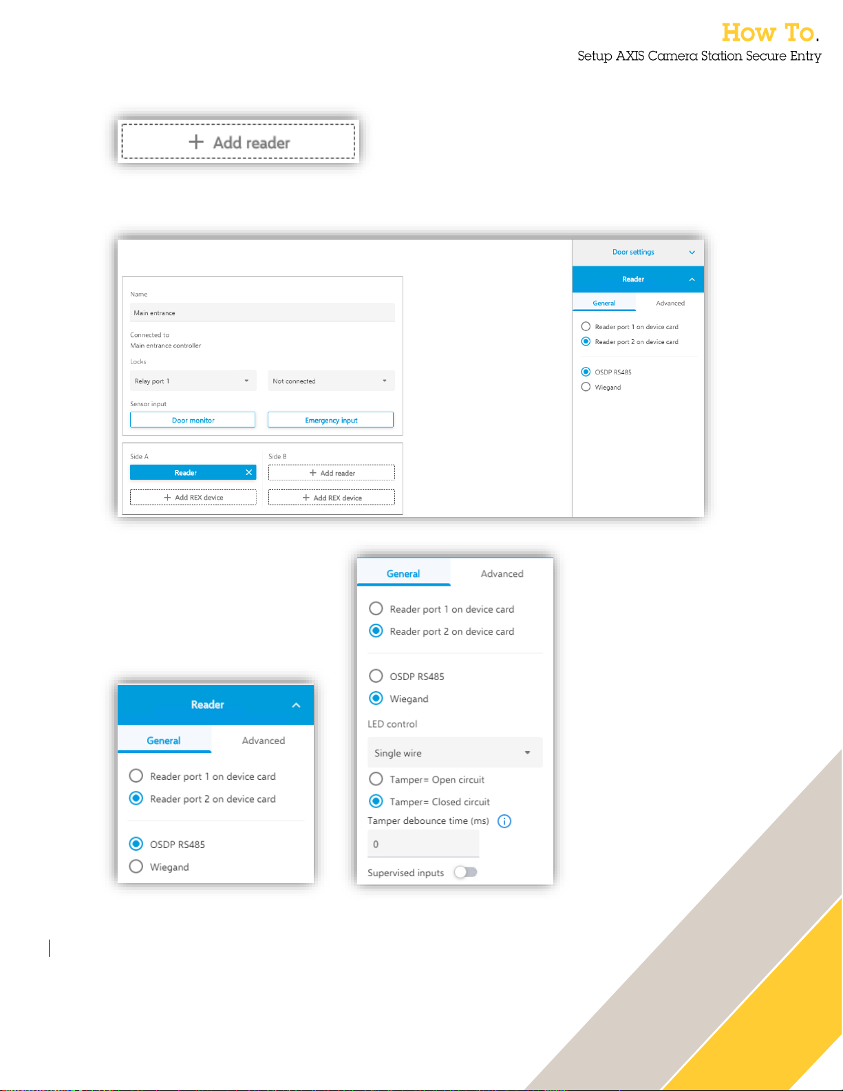
Reader settings
Add a reader by pressing this button either on the door Side A or Side B or both.
the reader. You can also configure if the reader is in tampered state when the circuit is open or
closed on the as well as configuring a debounce time to compensate for signal jitters.
When a reader is
selected the
“Selected peripheral”panel presents the
settings for the
individual reader.
Here you can
configure what reader
port you want to use
and if you are using
OSDP or Wiegand.
If selecting Wiegand
the specific
configurations needed
for Wiegand are
displayed. These
include if you have a
single wire LED
control or two wires
controlling red and
Page 21

21
REX settings
Add a REX device by pressing this button either on the door Side A or Side B or both.
Under the Advanced tab
you can also make unique
settings for card formats
and pin lengths to solve
specific needs on this
individual reader or
compensate for an
individual reader’s need to
have an adjusted card
format to get the
credential interpreted
correctly everywhere in
the system.
Page 22

22
Once the REX Device has been added the
settings for the REX is available in the
panel on the right-hand side of the screen
in the “Selected Peripheral”-part visible
under the settings.
You may select which specific IO that you
want the REX configured on as well as
choose whether the REX input really is a
request to exit or if it is a mechanical
override to the door, meaning it is more of
a notification that someone has exited
rather than an unlocking action being
needed.
You also configure how the system shall
interpret as the REX being activated. If
you are experiencing jittering signals you
can also set a debounce time on the input
signal to stabilize the signal
Page 23

23
Supervised inputs
Under Door monitor, Emergency input, Wiegand tamper and REX there is a possibility to
configure a input supervision, meaning the possibility to detect tampering attempts on the cable
by measuring a specific connection with end of line resistors mounted as close to the peripheral
device as possible.
Here you can see examples of the Parallel-first connection as well as the serial first connection
with the specified resistor values that are supported in the setups.
Page 24

24
PIN chart
Once all configurations on a door has been made and it’s saved the door is visible in the main
Doors and Zones view. From here you can select multiple doors in the system to set identification
profiles on multiple doors in unison or select to view the controller pin chart associated with the
selected door.
Page 25

25
When viewing the pin chart, it is also possible to print it out.
In the first release there is no way to leave the pin
chart view in a good way. You must go to another
menu and back to Doors and zones again to get
back to the door overview.
Page 26
26
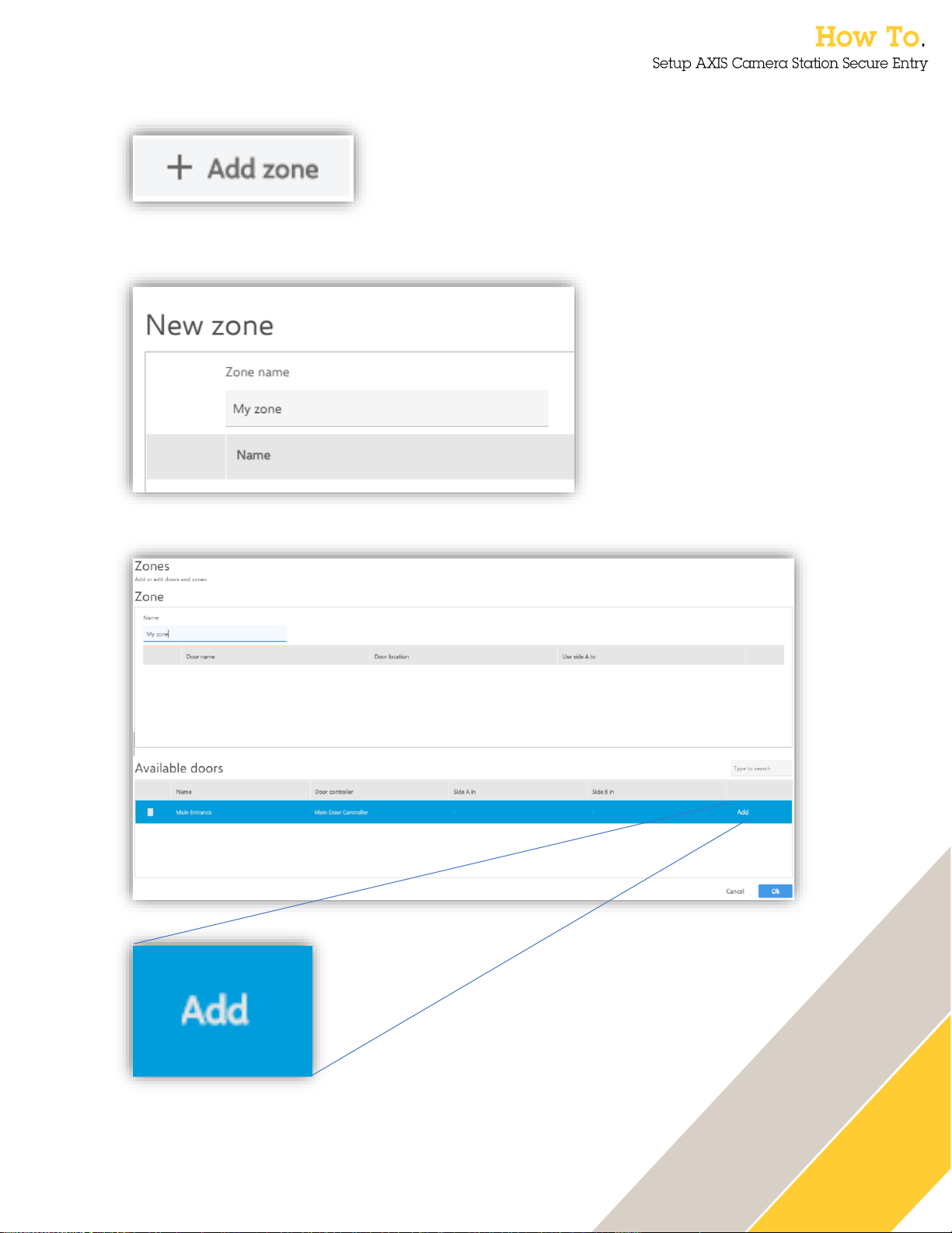
Add zone
To add a zone, click this button.
Give the zone a name.
When the zone has been added to the system a door can be added to the Zone by clicking on the
“Add”-button.
Page 27

27
When the door is in the zone it is possible to configure it as a perimeter door, meaning that
cardholders enter or exit the zone with the door, or as a door internally within the zone. These
settings are done with inline drop downs. Remove the door from the zone by pressing the X
furthest to the right.
When a zone is configured it is accessible as a tab on top of the system door list.
Page 28

28
Clicking the “+” in the top bar of AXIS Camera Station brings up this menu. This section will cover
the Access Management tab that can be opened from here.
In the Access management tab, there are four sub-views where things can be done.
• Access management dashboard
• Access management reporting
• Access management configuration
• Access management import and export
Page 29

29
In this view it is possible to add custom fields to the cardholder template in the access
management dashboard. Here is also where facility codes in cardholders’ credentials are enabled
and disabled in the system.
The action dropdown is where the action that will be done is selected.
• Import
• Export
• Restore
Page 30
30
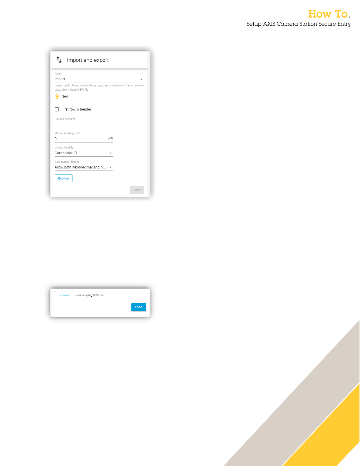
Import cardholder data
This function imports cardholders, cardholder groups and credentials from a CSV-file.
Select “New” if the imported data should be imported as a new database, wiping all stored data
currently in the system.
Check the box “First row is header” if the imported file contains column headers.
Input the delimiter that the imported file is formatted with.
Select the maximum allowed image size for cardholder photos.
Select what will be the Unique identifier linking cardholders between stored and imported data.
Choose if card numbers in the file will remain as they are in the import process or if conversion to
decimal or hexadecimal values is needed.
Click “Browse” to select a file.
When a file has been selected, Click “Load”.
Page 31

31
An import preview is shown and here the columns need to be linked to the system fields.
When all column headers have been assigned the import is started by Clicking on the “Import”
button.
Page 32

32
A notification will be shown when all the data has been imported.
Exporting cardholder data
There are no settings in the export action. To export the cardholders, cardholder groups and
credentials from the system click on the “Export” button.
Restoring from last import point
The system saves its state prior the last import action. If the import has been unsatisfactory, it is
possible to roll back the database to the version that was in place before the last executed import.
This action can only be done once and if multiple import actions have been done in a short period
of time the reset will only take the database one step backwards in time.
The user won’t get an error if they try to import a file
with wrong card number (eg. have a strange
character). The user can’t import the file, but don’t
know why.
Page 33

33
From the access management dashboard, it is possible to:
• add cardholders with credentials to the system.
• add cardholder groups to group cardholders together for easy management.
• create access rules to set levels of access on designated doors or zones, combining with
a schedule.
• configure unlock schedules for doors and zones.
• send commands to doors and zones to for instance lock or unlock.
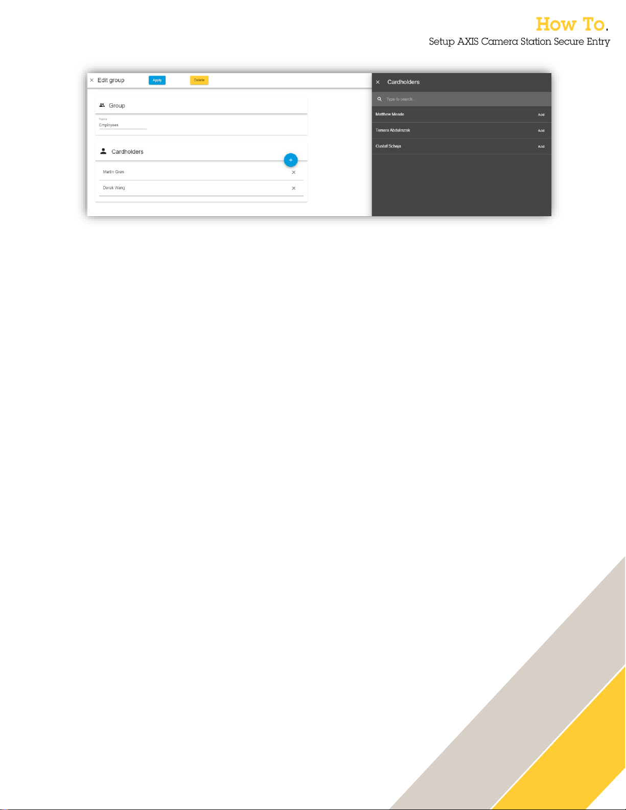
Adding a cardholder group
To add a cardholder group, click on the ‘+’-sign, and then select groups.
Page 34
34
The group needs a name. It is also possible to add existing cardholders in the group from the
system.
Page 35
35
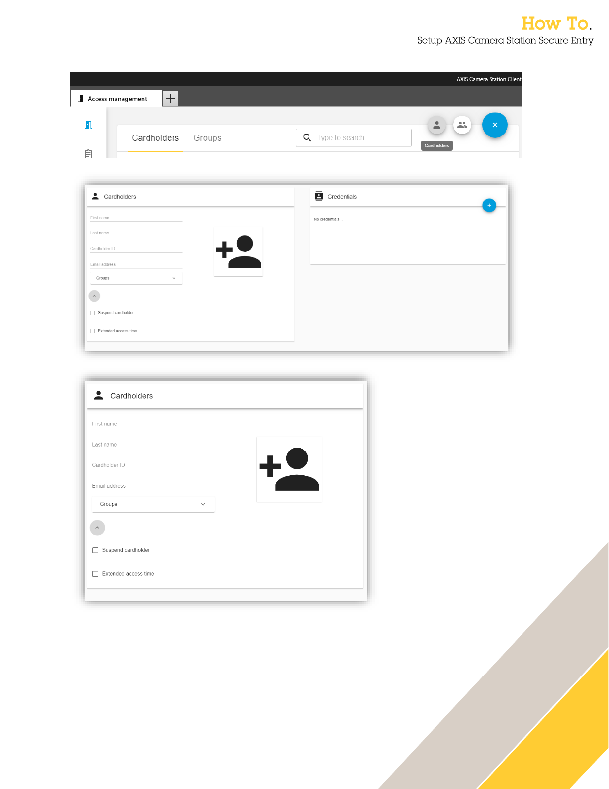
Adding and editing a cardholder
To add a cardholder, click the ‘+’-sign and then select the cardholder icon.
the arrow below the group’s selection.
To add a cardholder photo to the system, click on the Add
Photo-icon.
Here is where the
cardholder data is put
into the system.
The Cardholder ID is
a mandatory and
system unique field to
always be able to
identify a specific
cardholder. This is
due to all other data
for the cardholder may
change over time.
It is possible to
expand the cardholder
form with additional
features by pressing
Page 36

36
It is also possible to add the cardholder to an already created group from here.
Adding and editing a card credential
Page 37

37
To add a card credential, click on the ‘+’-sign on the credentials form.
Click on the card-icon.
Give the card a name and input the card number (Facility code will also be visible here if enabled
under Access management configuration). It is also possible to select a reader in the system to
retrieve the card data of the last swiped card from there.
Under expiration date it is possible to set different expiration settings.
• No end date – Credential will never expire
• Date – Set a date of expiration
• From first use – Select this option if you want to give access for a specific time after the
credential is first used.
• From last use – Select this option if you want to access to end if the credential is inactive
for a specific time.
Page 38

38
Adding and editing a PIN credential
To add a PIN Credential, click on the ‘+’-sign and then the PIN-icon.
A PIN Credential has no expiration. However, it is possible to configure a separate duress PIN
that still opens the door in normal operations but triggers a silent alarm in the system to alert
security staff if used.
Adding and editing access rules
From the access management dashboard access rules can be created. Create an access rule by
pressing the ‘+’-sign.
For duress PIN to work, authentication with card +
PIN is required for the validation to be non-
anonymous.
Page 39

39
An access rule is comprised of a name, schedules when the rule should be active, cardholders,
cardholder groups, doors and/or zones. It is possible to add all components of the rule from here
when adding or editing the access rule. Adding cardholders, cardholder groups, doors and zones
can also be done with multi-select drag-and-drop on the access management dashboard.
Edit door in access management
To edit a door in the access management dashboard, click on the edit-pen next to the door you
want to edit.
In this edit view it is possible to
A
B
C
Page 40

40
• see what zone the door is included in (A)
• set an unlock schedule (B)
• enable first person in rule for the unlock schedules (C)
Edit zone in access management
To edit a zone in the access management dashboard, click on the edit-pen next zone you want to
edit.
In this edit view it is possible to
• see the doors in the zone (A)
• set an unlock schedule (B)
o Note that it is not possible to apply a first person in rule on the zone.
Sending actions to doors and zones from the access management dashboard
Select one door or hold down the Ctrl-key and multiple select a number of doors or zones to send
door commands using the icon.
Page 41

41
Here it is possible to save some pre-defied reports from the system in a .csv-format.
Connect a split view or camera view to a door
Go to Configuration → Devices → External data sources to find a list of the configured doors in
the system. By clicking “Edit…” it is possible to connect the door to a designated camera view.
Page 42

42
Door plugin view
Open a new View tab by clicking on the “+”-sign and then choose Live view in the AXIS Camera
Station Client.
Right click on a view you want to include the assist and monitor in and select “Edit…”
Selecting the door views will list the configured doors. Drag and drop the view into the split
screen view. Save the view.
Page 43

43
Now it is possible to provide assistance to a cardholder as well as monitor the door’s current
transactions and status.
Data search (Access Control Event log with video link)
Opening a tab for Data search will show the access control specific event log together with the
associated view and recordings that are triggered on door events. Apply the dates and times you
want to investigate and press search.
Page 44
44
Hardware
Door monitor
A door position switch that sense physical state of the door (open or
closed) usually providing a closed circuit when the door is closed.
Emergency input
An input on the AXIS A1601 that can be configured through AXIS
Camera Station Secure Entry to initiate an unlocking or locking action
locally in the device. Normally these inputs are configured to be active
on an open circuit to accommodate for a scenario that the wire has
been cut.
OSDP
SIAs Open Supervised Device Protocol – Communication standard
between Access Control Units (Door controllers) and Peripheral
Devices (Readers)
Reader
A device that reads a cardholder’s different credentials.
REX
A Request to Exit device usually a button or a PIR-sensor indicating
that someone wants to exit the door.
A REX can also be configured that it does not unlock the door if it is
only a notification that a mechanical override, such as a panic bar or
mechanical opening handle has been used, to not send door forced
open events.
Wiegand
One of the oldest standardized ways to get card data from a reader.
Supported for legacy and compatibility purposes.
Access management
Card format
A card format is what defines how data is stored in a card. All data is
in binary so the card format in the system is a translation table
between the data stream the door controller is receiving from the card
reader to the data structure the door controller does access validation
on. Therefore, the card format in the solution has the possibility to
define different fields (bit ranges), encodings and bit and byte order
swapping. All to get the card number and / or the facility code we want
to validate
Card number
A facility code is a subset of the incoming data stream from the reader
and / or data stored on a card that is meant to identify the specific card
and / or cardholder
Cardholder
An access control user with a card or other credential whose main
purpose in the access control system is to get access through doors
where they need to go and not get through doors where they don’t
need to go.
Cardholder ID
A unique identifier for a specific cardholder, since names can change
and therefore also email addresses an attribute is needed for
identifying the specific cardholder in a system.
The cardholder ID is system unique and mandatory and can be
alphanumerical.
The filtering in the External Data Search is case
sensitive.
Page 45

45
Facility code
A facility code is a subset of the incoming data stream from the reader
and / or data stored on a card that can be encoded to be identical for a
specific end customer / site. Legacy access control systems used this
means to avoid any card duplicates when the id numbers started
running out.
Identification profile
An identification profile is a combination of one or more identification
types and one or more schedules. Administrators of the system can
apply an identification profile to one one or many doors to determine
how and when a cardholder gets access to that or those doors.
Identification type
Identification types are carriers of the credential information that
cardholders need to get access to a door. A means of identification.
Common identification types are tokens, such as cards (card raw, card
number) or key fobs, personal identification numbers (PINs),
fingerprints, facial maps, and request to exit (REX) devices. And
depending on the identification type, it can carry one or more types of
information.
Internal Door
Internal doors can only be part of one zone and is defined as inside
the physical zone.
Perimeter Door
Perimeter door in a zone moves cardholders between, into or out of
zones.
Zone
A zone is a group of doors designated to a specific physical zone. In
the future the zones can be applied in anti-passback-regulations as
well as people tracking. There are two types of doors in a zone. A
Perimeter door that moves cardholders between zones and internal
doors. Internal doors can only be part of one zone, but perimeter
doors can be part of two zones if they are physically adjacent and this
moving cardholders from one zone to another.
 Loading...