

Page 1
USER
MANUAL
AKA SERIES
File: 2015-05-25 ALN Aln-01 GB
Page 2

2 USER MANUAL
____________________________________________________________________________________________________________________
Contents:
1. General description ....................................................................................................... 4
2. Set ................................................................................................................................. 4
3. Safety rules ................................................................................................................... 5
4. Technical data ............................................................................................................... 6
5. General balance description .......................................................................................... 7
6. Keys and indicators ....................................................................................................... 9
7. Preparing working environment ................................................................................... 10
8. Preparing balance to work ........................................................................................... 11
9. General operation principles ........................................................................................ 12
10. Internal calibration ..................................................................................................... 13
11. Checking the balance ................................................................................................ 15
12. Connecting the balance to computer or printer .......................................................... 15
13. Start-up ..................................................................................................................... 19
14. Weighing with tare ..................................................................................................... 20
15. Scale menu ............................................................................................................... 21
16. Menu navigation rules ................................................................................................ 22
17. Scale setup (SEtUP) .................................................................................................. 28
17.1 Scale calibration (CALIb) .................................................................................... 29
17.2 Autozeroing function (AutotAr) ........................................................................... 33
17.3 Weight unit selection (UnIt) ................................................................................. 34
17.4 Serial port parameters setting (SErIAL) .............................................................. 35
17.5 Printout configuration (PrInt) ............................................................................. 36
18. Special functions description ..................................................................................... 38
18.1 Product and user identification (Prod and USEr) ................................................. 39
18.2 Pieces counting function (PCS) .......................................................................... 41
18.3 Percentage weighing function (PErC) ................................................................ 42
18.4 Label choosing function (LAbEL) ........................................................................ 43
18.5 Weighing animals function (LOC) ........................................................................ 44
Page 3

USER MANUAL 3
____________________________________________________________________________________________________________________
18.6 Constant tare memory function (tArE) ................................................................. 45
18.7 Maximum value indication function (UP) .............................................................. 47
18.8 Total weight function (totAL) ................................................................................ 48
18.9 Checkweighing function (thr) ............................................................................... 50
18.10 Setting date and time function (dAtE) .................................................................. 53
18.11 Statistical calculations function (StAt) .................................................................. 54
18.12 Function for summing recipe ingredients (rECIPE) .............................................. 57
18.13 Density determination (dEnSItY) .......................................................................... 58
19. Troubleshooting and maintenance ........................................................................... 61
Declaration of Conformity ............................................................................................ 62
Page 4

4 USER MANUAL
Certificate of ISO quality system Certificate of balance type approval
DIN EN ISO 9001:2000
____________________________________________________________________________________________________________________
1. General description
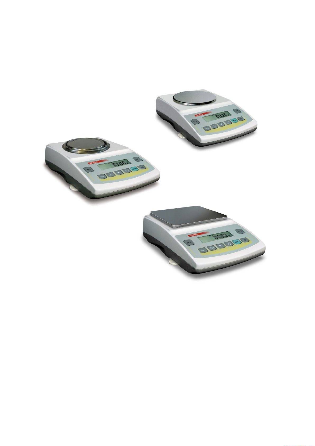
AKA/AKZ series balances are destined for high accuracy weighing in laboratory practice.
All balances are metrologically tested. According to an order balances can be calibrated or legally verified.
Balances with legal verification comply with certificate of type approval and are marked with the following
legal and securing items:
- green metrological mark placed on the balance name plate,
- notified body stamp (number of notified body) on the balance name plate,
- protective seals placed on: an edge of balance name plate, the casing mounting screw and in the place
of access to adjustment switch,
In order to renew legal verification please contact authorized service of AXIS.
Balance classification according to PKWiU: 33.20.31.
Certificates:
2. Set
A standard set consist of:
1. Balance,
2. Pan support and a pan,
3. Feeder 12V / 1,2A,
4. User manual,
5. Guarantee card
Page 5
USER MANUAL 5
It is necessary to follow safety rules of work with the
balance shown below. Obeying those rules is the
condition to avoid electrical shock or damage of the
balance or connected peripheral devices.
Repairs and necessary regulations can be done by authorised personnel
only.
To avoid fire risk use a feeder of an appropriate type (supplied with the
balance) and supply voltage have to be compatible with specified
technical data.
Do not use the balance when its cover is opened.
Do not use the balance in explosive conditions.
Do not use the balance in high humidity environment.
If the balance seems not to operate properly, switch it off and do not use
until checked by authorised service.
According to current acts of low about protection of
natural environment, wasted balances should not be put
into waste containers together with ordinary waste.
Wasted balance after operation period can be delivered to units
authorized for gathering wasted electronic devices or to the place where it
was bought.
____________________________________________________________________________________________________________________
3. Safety rules
Page 6
6 USER MANUAL
Type
AKA120
AKZ120
AKA220
AKZ220
AKA320
AKZ320
AKA520
AKZ520
Load (Max)
120g
200g
300g
500g
Load (Min)
0,02g
0,02g
0,02g
0,02g
Readout unit (d)
0,001g
0,001g
0,001g
0,001g
Verification unit (e)
0,01g
0,01g
0,01g
0,01g
Tare range
-120g
-200g
-300g
-500g
Accuracy
II
Repeatibility
0,001mg
Non-linearity
0,002mg
Work temp.
+18 ÷ +35°C
Weighing time
<3s
Pan size
115mm
Balance dim. (with legs)
215(235 with legs)x345x90mm
Interface and equipment
RS232C, USB, PS2, clock (option: LAN or Wi-Fi)
Supply
~230V 50Hz 6VA / =12V 1,2A
Scale weight
5kg
Recommended standard of
mass
F2 100g
F2 200g
F2 200g
F1 500g
Type
AKA1200
AKZ1200
AKA2200
AKZ2200
AKA3200
AKZ3200
AKA4200
AKZ4200
AKZ10
Load (Max)
1200g
2200g
3000g
4200g
10kg
Load (Min)
0,5g
0,5g
0,5g
0,5g
5g
Readout unit (d)
0,01g
0,01g
0,01g
0,01g
0,1g
Verification unit (e)
0,1g
0,1g
0,1g
0,1g
1g
Tare range
-1200g
-2200g
-3000g
-4200g
-10kg
Accuracy
II
Repeatibility
0,01g
0,1g
Non-linearity
0,02g
0,2g
Work temp.
+18 ÷ +33°C
Weighing time
<3s
Pan size
165x165mm
195x180mm
Balance dim. (with legs)
215(235 with legs)x345x90mm
Interface and equipment
AKA/G or AKZ/G: RS232C, USB, PS2, clock (optional: LAN or Wi-Fi)
AKA or AKZ: RS232C (optional: USB, PS2, clock, LAN or Wi-Fi)
Supply
~230V 50Hz 6VA / =12V 1,2A
Scale weight
5kg
Recommended standard of
mass
F2 1000g
F2 2000g
F2 5000g
____________________________________________________________________________________________________________________
4. Technical data
Caution:
E2 is international symbol of calibration weight class according to O.I.M.L. Some requirements for weight
accuracy are connected with this class.
Page 7
USER MANUAL 7
7
6
1
2
4
5
7
6
1
2
4
3
5
8
____________________________________________________________________________________________________________________
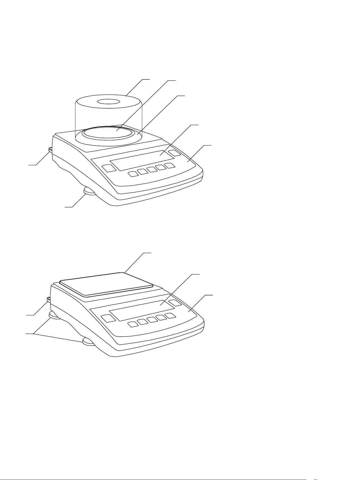
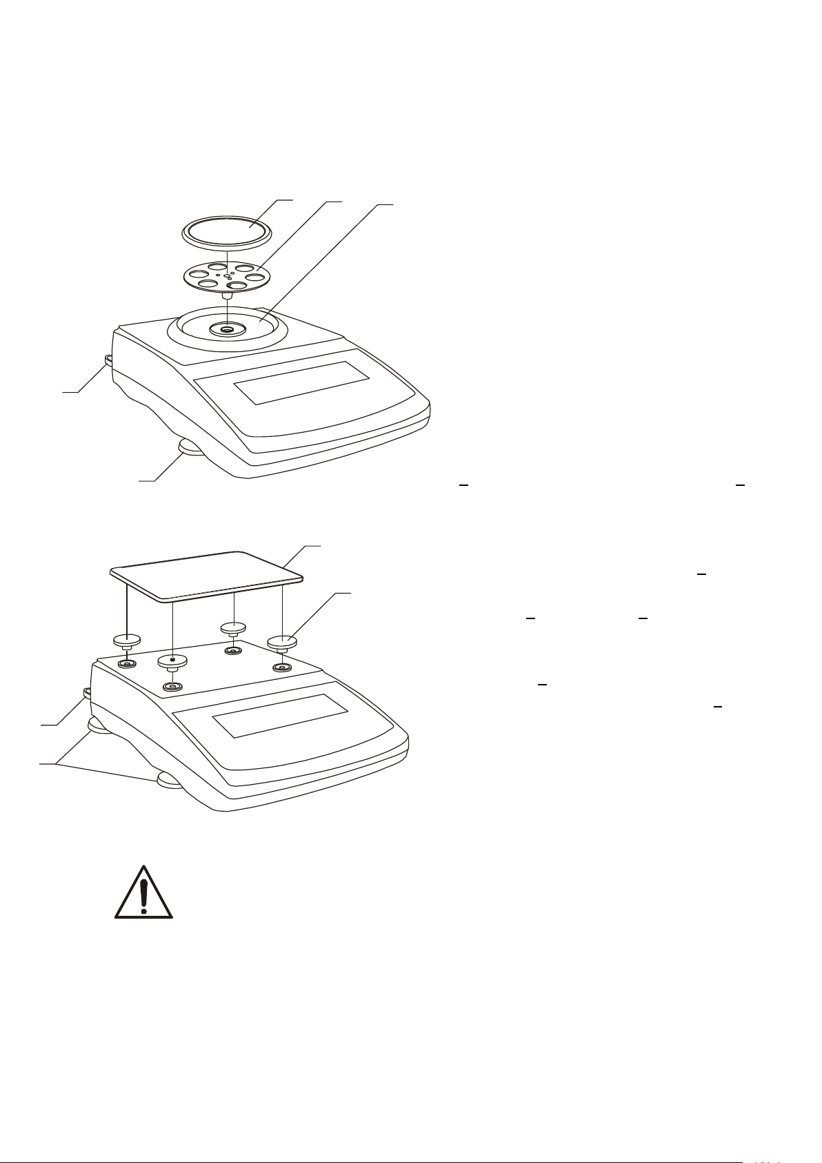
5. General balance description
AKA100-AKA520, AKZ100-AKZ520 balances:
1 – pan
2 – pan support
3 – pan ring
4 – display LCD
5 – keys
6 – rotating legs
7 – water level
8 – draft shield
AKA1200-AKA4200 , AKZ1200-AKZ10 balances:
1 – pan
2 – nuts (under pan)
4 – LCD display
5 – keys
6 – rotating legs
7 – water level
Page 8
8 USER MANUAL
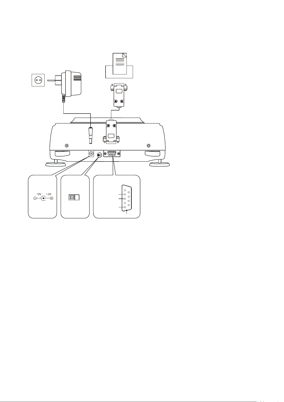
Feeder
~230V/50Hz
Printer
or computer
ON
OFF
Adjustment
switch
RxD (receiver)
TxD (transmitter)
GND
Case
RS232C
Feeder
1
2
3
4
5
6
7
8
9
____________________________________________________________________________________________________________________
Connectors view:
Page 9
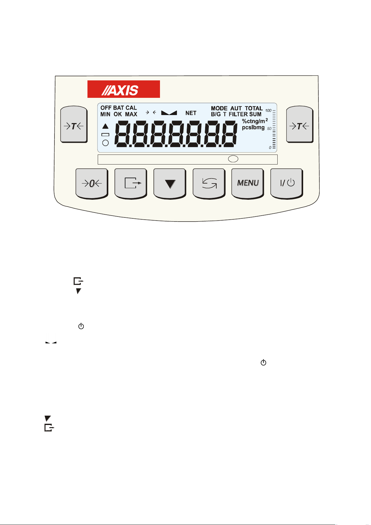
USER MANUAL 9
Description of basic key functions and indicators:
T
- tarring (enter mass subtracted from weighed mass)/ confirmation of selected
menu options,
0
- zeroing (option),
- result printout (transmission),
- internal calibration,/ accelerated options viewing
- switch: special function/ weighing,
MENU
- enter to special function menu,
I/
- switch on / switch off (standby),
indicator
- shows stabilization of weighing result,
linear indicator
- indicator of balance load (0-100%),
OFF indicator
- appears after the balance is switched off with I / key,
distinction of last digit
- informs that reading unit value is lower than acceptable indication error
(balances with legal verification, de)
Max, Min, d, e, I
- metrological parameters of the balance.
0
kg
Max Min e= d= I
____________________________________________________________________________________________________________________
6. Keys and indicators
The use of keys during entering numeric values (special functions):
- increment current digit,
- insert comma,
T
- move to next position,
MENU - finish entering.
Page 10
10 USER MANUAL
+18°C
+33°C
____________________________________________________________________________________________________________________
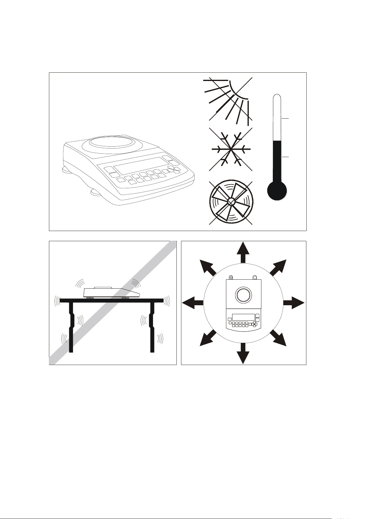
7. Preparing working environment
Location for the balance should be chosen with care in order to limit influence of the factors that can
interrupt working balance. This location has to maintain proper temperature for working balance and
necessary space for its operating. The balance should stay on stable table made of material that does not
influence magnetically on the balance.
Rapid air blasts, vibrations, dust, rapid temperature changes or air humidity over 75% are not allowed in
balance surrounding. The balance should be far from heat sources and devices emitting strong
electromagnetic or magnetic fields.
Page 11
USER MANUAL 11
If the balance was taken from a lower temperature surrounding to a room with
higher temperature, e.g. in winter, moisture can liquefy on the balance casing.
Do not connect power supply to the balance, because this can cause damage
or improper work of the balance. In this case leave the balance for at least 4
hours unplugged for acclimatization.
7
6
1
2
3
7
6
1
2
____________________________________________________________________________________________________________________
8. Preparing balance to work
1. Take the balance, the feeder and
mechanical elements of the pan out. It is
recommended to keep the original scale
package in order to transport the
balance safely in future.
2. Place the balance on a stable
ground not affected by mechanical
vibrations and airflows.
3. Level the balance with rotating legs
6 so that the air bubble in water level 7
at the back of the balance is in the
middle.
4. (for AGC100-AGC600) Gently insert
the mandrel of pan support 2 into
balance mechanism socket through the
pan ring 3 and the pan 1 on (AGC600
balances have not pan ring).
5. (for AGC1000-AGC4000, AGZ10C)
Place nuts 2 on mandrels that are visible
in balance cover holes, put the pan 1 on
nuts.
Page 12
12 USER MANUAL
Do not overload the balance more than 20% of maximum capacity.
Do not press the pan with a hand.
For transportation take off the pan (move it gently and lift it up) and pan support (lift it up)
and protect from any damages.
____________________________________________________________________________________________________________________
9. General operation principles
1. Weighed sample should be placed in the centre of the pan.
2. Weighing result should be read when the indicator " " lights, which signalises stabilisation of a result.
3. The balance allows tarring in the whole measuring range. To tare the balance press T key (on the left
or on the right). Tarring does not extend measuring range, but only subtracts tare value from mass value
of a sample placed on the pan. To make the control of pan load easier and to avoid crossing
measurement range, the balance has a load indicator calibrated 0÷100% Max.
4. In direct sale use (d=e), make sure that zero indicator is displayed before sample is placed on the pan.
If not, press key and wait until the balance is zeroed and zero indicator appears. In other balances the
key does not operate.
5. When the balance is not used but should be ready to work immediately, it can be switched off by pressing
I/ key. The backlight of balance reading system is then switched off and the balance enters into
"standby" mode, in which the balance maintains internal temperature and ability to start working with
maximum accuracy. Standby mode is signalled by the OFF indicator. To switch the balance on press I/
key.
6. The balance cannot be used to weigh ferromagnetic materials due to decrease of weighing accuracy.
7. Balance mechanism is a precise device sensitive to mechanical shocks and strokes.
8. After every change of balance position, level the balance and perform internal calibration using key.
Page 13

USER MANUAL 13
____________________________________________________________________________________________________________________
10. Internal calibration
The balance is equipped with internal calibration system, which general task is to maintain required
measurement accuracy on the balance.
Internal calibration is the process of putting internal weight on automatically by balance mechanism and
correcting accuracy in balance firmware. The correction is necessary because of differences between
values of gravitational acceleration in the place where the balance was manufactured and in the place
where it is operated, as well as due to changes of balance level and temperature.
Internal calibration is performed in the following situations:
- when key is pressed,
- after defined time interval (for legally verified balances - 2 hours),
- after temperature change (for legally verified balances – more than 2oC).
In legally verified balances time interval is set to 2 hours and defined temperature change is 2oC. In not
legally verified balances those values can be set as calibration options. The reason of starting internal
calibration is shown as an icon near weight picture.
Page 14
14 USER MANUAL
g
g
~45 seconds
____________________________________________________________________________________________________________________
In order to perform internal calibration proceed with the following:
Empty the pan.
Press key twice (double pressing the key
helps to avoid accidental starting calibration
procedure).
During calibration internal weight is put three
times on and obtained results are compared.
Discrepancy of results is signalled with a
message and causes the balance being blocked.
Until calibration process is finished do not
perform any operation on the balance. Any
vibrations and shocks interfere calibration
process and may delay it or deteriorate accuracy
of its result.
When internal calibration is performed
successfully the balance indicates zero on the
display at empty pan.
Note:
In order to terminate calibration process in not
legally verified balances press key and wait
until balance mechanism is not settled in initial
position.
Page 15

USER MANUAL 15
_________________________________________________________________________________________________________________
11. Checking the balance
In order to confirm correctness of the balance during its operation, before starting and after finishing every
measurement series it is advised to check weighing accuracy. It can be done by weighing external
calibration weight or other object with exactly known mass.
If exceeding of allowable measurement error is affirmed, the following things should be checked:
- if the balance stands stable and it is levelled,
- if the balance is exposed on rapid air blasts, vibrations, rapid temperature changes or air humidity,
- if the balance is not affected directly by heat source, electromagnetic radiation or magnetic field.
The cause of inaccuracy can be too low temperature of the balance as well, when it was unplugged from
power supply. In this situation leave the balance switched on for several minutes in order to adjust its
internal temperature.
If none of above causes of inaccuracy occurs, calibration with external weight should be performed to the
balance. Recommended external calibration weight (to buy for additional charge) is given in technical data
table. In order to calibrate the balance with external weight in legally verified balances verification seals
should be removed and another legal verification should be performed. In this case it is recommended to
contact authorized service centre.
Calibration with external weight is described in details in chapter 17.1.
12. Connecting the balance to computer or printer
The scale can be equipped with one or two serial interfaces RS232C, USB, LAN or Wi-Fi designed to
cooperate:
- with computer – the scale sends data after pressing key or after initiation signal from
computer,
- with printer - sending data after pressing key or automatically after putting on/off a sample
and measurement stabilization,
- with label printer – after pressing the scale sends set of instructions for label printer starting
from label number set in special funcion LabEL.
Set of send data is set using special function PrInt.
The following data can be send:
- Header (scale type, Max, d, e, serial number),
- Operator identification number,
- Successive printout number (measurement),
- Identification number or product bar code,
- Number of pcs (PCS function only),
- Single detail mass (PCS function only),
- Nett weight,
- Tare (package mass),
- Gross weight,
- Total mass (Total function only).
The way of sending data and transmission parameters is set using SErIAL special function.
Page 16

16 USER MANUAL
Byte
1 - sign „-” or space
Byte
2 - space
Byte
34
-
digit or space
Byte
5÷9
-
digit, decimal point or space
Byte
10 - digit
Byte
11 - space
Byte
12 - k, l, c, p or space
Byte
13 - g, b, t, c or %
Byte
14 - space
Byte
15 - CR
Byte
16 - LF
__________________________________________________________________________________________________________________
If the scale is equipped with two serial joints (interfaces) Print and SErIAL function is set independently for
both interfaces.
If scale cooperates with a computer then the computer must have a special program. Dedicated programs
are also offered by AXIS.
Needed drivers and instructions can be found on the CD supplied with Axis scales.
12.1 Detailed LonG protocol description
Standard communication parameters: 8 bits, 1 stop bit, no parity, baud rate 9600bps,
After using key, measurement data is send together with text description (NET, TARE, GROSS) – all
set by using Print option. If Print isn’t set then only scale indication is send (as below).
Data exchange (communication):
Readout of scale indication
ComputerScale: S I CR LF (53h 49h 0Dh 0Ah),
ScaleComputer: scale response according to description below (16 bytes):
Attention:
Network number different than zero (SErIAL / nr function) changes scale working mode: communication
with a computer is possible after logging the scale in with 02h scale number command. To log the scale out
use 03h command.
For example: Using a program to test RS232 interface ( program is available in www.axis.pl / programy
komputerowe ) for scale number 1 please write: $0201 to log in, then SI, and write: $03 to close
communication.
Asking about scale presence in system (testing scale connection with computer):
ComputerScale: S J CR LF (53h 4Ah 0Dh 0Ah),
ScaleComputer: M J CR LF (4Dh 4Ah 0Dh 0Ah),
Displaying a inscription on scale’s display (text communicate from computer):
ComputerScale: S N n n X X X X X X CR LF, nn-displaying time in seconds; XXXXXX-6 signs to
display
ScaleComputer: M N CR LF (4Dh 4Eh 0Dh 0Ah),
Scale tarring (calling T key press) :
ComputerScale: S T CR LF (53h 54h 0Dh 0Ah),
ScaleComputer: without response,
Page 17
USER MANUAL 17
SCALE
KAFKA PRINTER
SCALE
COMPUTER
_________________________________________________________________________________________________________________
Scale zeroing (calling 0 key press):
Computer Scale: S Z CR LF (53h 5Ah 0Dh 0Ah),
Scale Computer: without response,
Scale turning on / off (calling I/ key press):
Computer Scale: S S CR LF (53h 53h 0Dh 0Ah),
Scale Computer: without response,
Entering to special function menu (calling MENU key press):
Computer Scale: S F CR LF (53h 46h 0Dh 0Ah),
Scale Computer: without response,
Setting threshold 1 value (option):
Computer Scale: S L D1...DN CR LF (53h 4Ch D1...DN 0Dh 0Ah)
D1...DN – threshold value, maximum 8 characters („-” – negative value, digits, dot – decimal
separator), number of digits after dot should be the same as on scale display,
Scale Computer: without response,
Example:
in order to set low threshold 1000g in scale B1.5 (d=0.5g) the following order should be sent:
S L 1 0 0 0 . 0 CR LF (53h 4Ch 31h 30h 30h 30h 2Eh 30h 0Dh 0Ah),
in order to set low threshold 100kg in scale B150 (d=50g) the following order should be sent:
S L 1 0 0 . 0 0 CR LF (53h 4Ch 31h 30h 30h 2Eh 30h 30h 0Dh 0Ah),),
Setting threshold 2 value (option):
Computer Scale: S H D1...DN CR LF (53h 48h D1...DN 0Dh 0Ah),
D1...DN – threshold value, maximum 8 characters
Scale Computer: without response.
Setting threshold 3 value (option):
KomputerWaga: S M D1...DN CR LF (53h 4Dh D1...DN 0Dh 0Ah),
gdzie: D1...DN – threshold value, maximum 8 characters
WagaKomputer: without response.
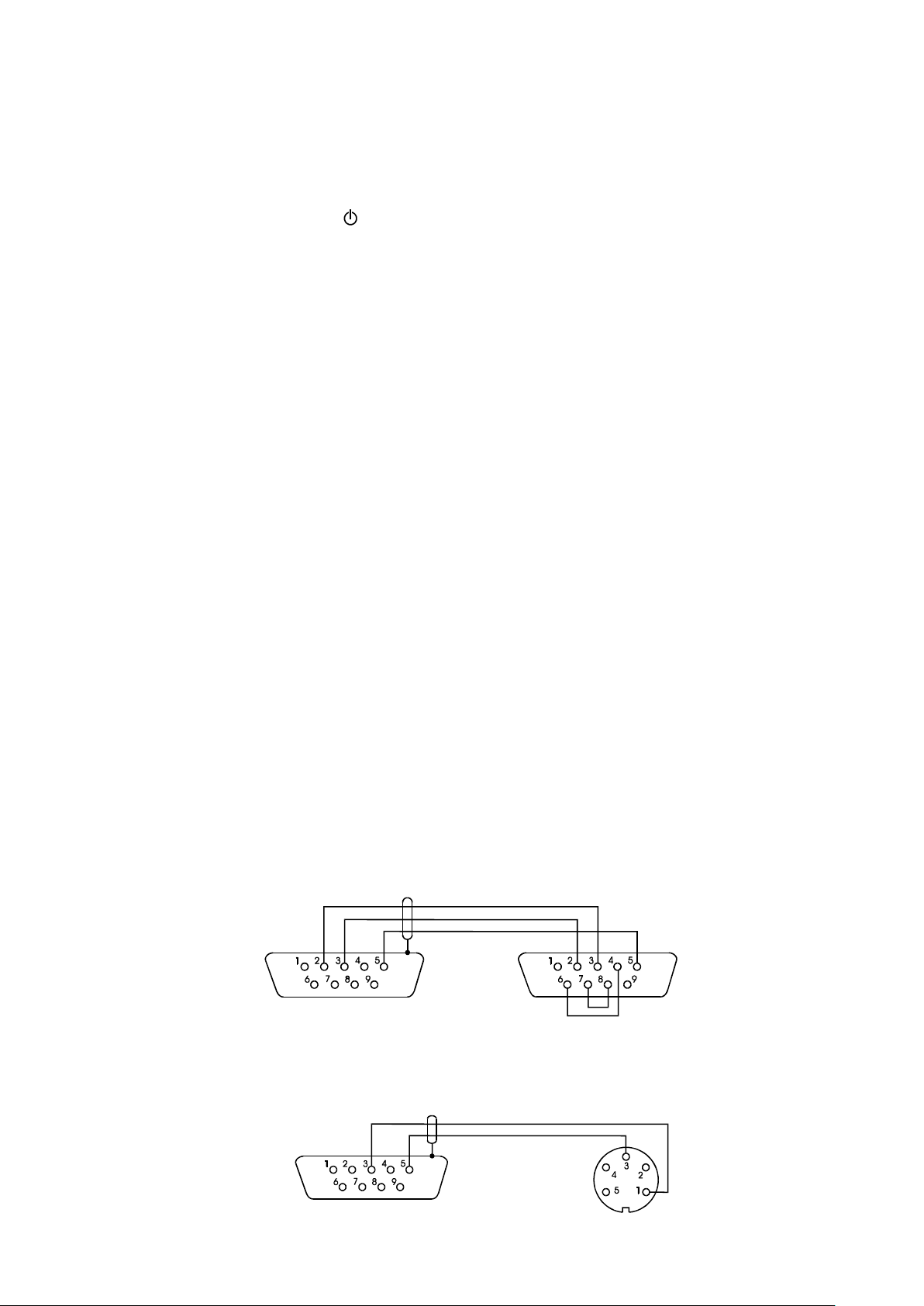
Connecting cable WK-1 (scale – computer / 9-pin interface):
Connection cable WD-1 (connects scale with AXIS printer):
Page 18

18 USER MANUAL
SW-1
SW-2
SW-3
SW-4
SW-5
SW-6
SW-7
SW-8
on
off
on
off
off
on
off
off
US -
Steering instruction
FR"0001"
- Label number define instruction
? -
Instruction that starts list of variable signs
mm:gg
- 5 signs: minutes:hour
rrrr.mm.dd
- 10 signs: year.month.day
masa
- 10 signs: scale indication+ mass unit
P1 -
Steering instruction
__________________________________________________________________________________________________________________
Setting of internal switches of AXIS printer:
12.2 Detailed EPL protocol description
Transmission parameters: 8 bits, 1 stop bit, no parity, baud rate 9600bps,
After using key in scale:
ScaleLabel printer : set of instruction in EPL-2 language that initialize label printing:
Attention:
1. Except variable signs constant signs can also be inscribed e.g. factory name, product name and so on.
2. In standard only one label pattern is possible to printout (number 0001). Using bigger amount of
patterns (other label numbers) is possible thanks to LAbEL special function.
3. To achieve label printout, label printer must have inscribed label pattern (label pattern is created on
computer and using computer it is saved to label printer memory). Label pattern is designed by ZEBRA
DESIGNER program which is supplied together with label printer.
4. Scales parameters and transmission protocol must corespond to label printer type.
Page 19

USER MANUAL 19
g
~45 seconds
0
Max Min e= d= I
kg
_________________________________________________________________________________________________________________
13. Start-up
Plug feeder into 230V power supply socket. When
the pan is empty plug feeder output connector into
12V socket at back of the balance. Autotests and
internal calibration will be performed.
Scale display test (autotests of internal electronic
elements C1:8 displayed only when any test result
is negative)
Displaying firmware version.
Test of internal calibration.
Internal calibration (in not legally verified balances
can be terminated using key – CAL End
communicate confirms).
After zeroing the balance is ready to weighing.
It is recommended before making measurements to wait until internal temperature of
balance stabilize. To accomplish that, the balance should be turned on for more than 2
hours before measurements. From the perspective of measurements accuracy
continuous balance operation is beneficial.
Page 20

20 USER MANUAL
00
g
g
g
g
g
__________________________________________________________________________________________________________________
14. Weighing with tare
If the scale is not loaded and 0
indicator doesn’t indicate, press 0
key.
Zero indication and 0 indicator mean
that the scale is ready to work.
After putting container (package) tare the
scale using T key. NET indicator will
show up.
Put on weighted object and readout net weight
(NET indicator shows that scale indicates net
weight).
In order to readout gross weight press key
(B/G indicator shows that scale indicates gross
weight). Press again key in order to come
back to net indications.
Page 21

USER MANUAL 21
g
_________________________________________________________________________________________________________________
15. Scale menu
All scales except for basic metrological functions: weighing and taring, have many special functions and
configuration options.
In order to ease using functions user can create
his own (personalized) menu.
Creating personalized menu:
In „out of the box” scale after pressing MENU
key only SEtuP option (it contains all
configuration options) is available.
One of the configuration options is Menu that is
used to create personalized menu.
To add a function to personalized menu press
T
key when the function is indicating.
Chosen function is indicated with „o” sign on the
left side of display.
After adding all necessary functions press out in
order to come back to weighing mode. User now
after pressing MEnu key has access to selected
earlier functions and to SEtuP option.
dEFAULt option is used to set factory settings.
Page 22

22 USER MANUAL
g
0
g
__________________________________________________________________________________________________________________
16. Menu navigation rules
Choosing menu options:
Scale menu shows up after pressing Menu key.
First menu position is displayed for about 10
seconds. After 10 seconds successive menu
positions are displayed automatically.
Choosing menu position (option) is done by
pressing T key when it is displayed on the
screen.
After choosing position (option) usually several
options show up:
on – turning on selected option,
OFF - turning off,
out – out to menu.
Accelerated working with menu:
First menu position is displayed for about 10s.
User can change menu positions manually by
pressing key.
Immediate out to previous menu level is done by
using Menu key.
Page 23

USER MANUAL 23
g
g
g
g
_________________________________________________________________________________________________________________
key working method:
During standard weighing key is used to
switch between net and gross indication.
When special function e.g. PCS is turned on,
using key enables to go back to standard
weighing mode.
Sign „o” on the left side signalizes that special
function is turned on and user can go back to
function mode by pressing key.
Page 24

24 USER MANUAL
__________________________________________________________________________________________________________________
Inscribing numerical values:
Inscribing numerical values is needed in some
special functions e.g. tArE function requires to
inscribe tare values.
Keys:
- decimal point,
T
- next digit position,
- increasing digit inscribed value (use also
0),
MENU – end of inscribing.
Page 25

key
(PCS)
(totAL)
...
...
out
SEtUP
Prod
USEr
PCS
Unit
PErc
LOC
tArE
UP
totAL
thr
StAt
rECIPE
out
()o()o
MEnu
CALIB
AutoZEr
UnIt
MENU
- personalized function menu created using SEtUP / MEnu
- sensitivity calibraton (only not verificated scales)
- fast calibration (without confirmation of putting weight)
- calibration with confirmation
- calibration report printout
- internal calibration time interval
- internal calibration temperature interval
- exit
- autozeroing
- autozeroing on
- autozeroing off (lasts 10min)
- exit
- settings
- creating menu (” “- added to menu)
- choosing product
- choosing user
- pieces counting function
- actual unit selection
- percentage conversion function
- animals weighing function
- tare memory bank
- maximum value function
- summation series of measurements function
- threshold values comparing function
- statistics function
- recipe weighing function
- exit
o
CAL on
CAL StP
CAL Prn
CAL tM
CAL C
out
Aut on
AUt OFF
out
CArAt (ct)
MGrAM (mg)
HGrAm (kg)
Pound (Ib)
ounCE (oz)
ounCE (ozt)
GrAin
PEnnYW
GrAM (g)
out
- unit choice
- carat
- miligram
- kilogram
- pound
- ounce
- aphotecary ounce
- grain
- jednostka jubilerska
- gram
- exit
USER MANUAL 25
_________________________________________________________________________________________________________________
Menu diagram:
Page 26

26 USER MANUAL
SErIAL
PrInt
dAtE
- setting time and date (if the scale is equipped with clock)
- date and time off
-
- set date and time
- accoes code
- data format
- time format
- exit
date and time on
- serial ports settings settings
- port - 1
- transmission speed (1200, ... ,115 200 bps)
- bits quantity (7 or 8)
- parity control
- transmission type (Stab, no StAb, Auto,Cont.,rEMoVE)
- protocol (LonG, EPL, EPL_A, EPL-d, PEn-01)
- barcode reader MJ4209 cooperation
- exit
- port-2 (as above)
- printout data configuration / transmission
- port - 1
- header (scale type, Max, d, e, serial nr)
- scale operator id number
- data
- time
- succesive printout/measurement number
- product identification number
- product barcode number
- product name
- pieces quantity (PCS function)
- product unit weight
- net weight
- package weight (tare)
- gross weight
- total weight (totAL function)
- measurement number and value in one line printout
- exit
- port-2 (as above)
- exit
bAUd
bItS
PArItY
SEndInG
Prot
SCAnn
out
HEAdEr
User Id
dAtE
tIME
Prn no
Prod Id
Prod bA
Prod nA
Cont
APW
nEt
P tArE
Gross
totAL
nr LCD
out
Port-1
Port-2
out
dAt oFF
dAt on
dAt SEt
dAt PIn
dat For
tM For
out
Port-1
Port-2
out
__________________________________________________________________________________________________________________
Page 27

USER MANUAL 27
(bAttEry)
(AUto OFF)
(ZEro)
dEFAULt
SErVICE
out
- turn on/off accumulator charging (if the scale is equipped with accumulator)
- automatic turning off - saving accumulator power (as above)
- scale start zero inscribing (factory zero)
- restore default settings for all options
- options only for service
- exit
_________________________________________________________________________________________________________________
Page 28

28 USER MANUAL
g
__________________________________________________________________________________________________________________
17. Scale setup (SEtUP)
SEtUP contains all options used for setting scale
work mode:
MEnu – creating personalized user menu,
CALIb – scale sensitivity calibration,
AutoZEro(ing) – self-maintaining zero indication
(unloaded scale),
UnIt – weight unit selection,
SErIAL – setting serial ports,
Print – transmission (printout) data selection,
dAtE – inscribing actual date and time,
FirMW(are) – uploading new firmware (only for
service)
dEFAULt – reset to factory settings,
SErVICE – service menu (only for service).
Page 29

USER MANUAL 29
ON
OFF
Przełącznik
adjustacji
Cecha zabezpieczająca
dostęp do przełącznika
adjustacji
_________________________________________________________________________________________________________________
17.1 Scale calibration (CALIb)
Calibration with external weight should be performed if balance accuracy after internal calibration is not
satisfactory. Calibration weight stated in technical data table for the balance (or of better accuracy) with
valid verification certificate should be used then.
Calibration of legally verified balance requires violating a mark used to protect an access to
adjustment switch and results in loosing legal verification. To renew legal verification of the
Before proceeding with calibration for balances comply with verification requirements, adjustment switch
should be set to ON position using thin screwdriver (the balance will display the message Pr ON).
When calibration process, described on next page, is finished, the balance will display the message Pr ON.
Adjustment switch should be set to OFF position using thin screwdriver (the balance will move to weighing).
balance, it is necessary to contact a service or notified body.
In balances comply with verification
requirements performing calibration requires
changing adjustment switch position, which is
placed behind protecting mark (sticker) of a
notified body. An access to the switch is
possible only after removing the mark.
Page 30

30 USER MANUAL
0
g
g
100g
g
__________________________________________________________________________________________________________________
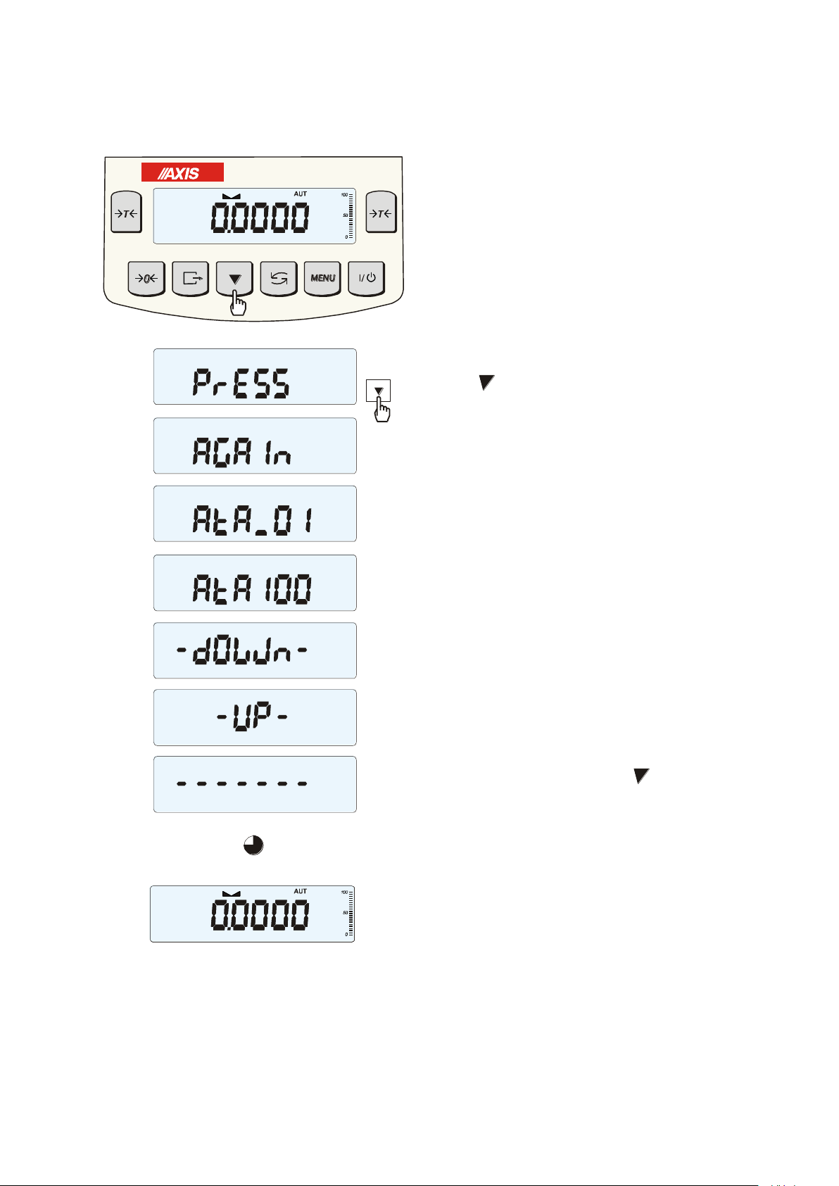
Calibration with external weight:
Press MENU key.
Press T key when CALIb function appears.
The following options will be displayed:
-CAL on – calibration with external
recommended standard of mass (see technical
data).
-CAL StP – calibration with external weight,
confirmation of successive steps - MENU key,
out – leave without changes
- CAL Prn – calibration report,
- CAL tM – set time interval for internal
calibration,
- CAL C – set temperature difference for
internal calibration,
- out.
Press T key when CAL StP option appears
(calibration in two steps).
Press T key when weight value used for
calibration is indicating or use othEr option and
inscribe proper value ( keys 0 , ,
T
)
Press MENU and wait for writing zero to the
scale.
When LOAD message appears put standard of
mass on the pan. Press MENU key (CAL on
doesn’t need pressing MENU key).
Wait until internal calibration is finished and zero
indication is displayed.
Page 31

USER MANUAL 31
_________________________________________________________________________________________________________________
Internal calibration options:
Internal calibration of the balance is performed automatically every time the balance is switched on,
additionally after given time interval during work and after every temperature change of more than given
value.
In order to perform internal calibration in any moment, empty the pan and press key twice (one more
pressing terminates calibration).
Press MENU key to display function menu and
choose CALIb function by pressing T key
when it is displayed.
The following options will appear:
- CAL on – perform calibration with external weight
- CAL Prn – printout of calibration report
- CAL tM – set time interval for internal calibration
(1h – 6h)
- CAL C - set temperature difference for internal
calibration (1C - 4C)
-out – switch internal calibration off
for internal calibration
Press T key when CAL tM option is displayed.
Predefined time intervals for internal calibration will
be displayed. Select required value pressing T
key.
Accordingly choose CAL C option pressing T
key and selecting values of temperature difference.
Select out option to finish.
Page 32

32 USER MANUAL
--------- CALIBRATION REPORT ----------
ALN220 MAX=220g e=0.001g d=0.0001g
S/N : 1234
PROD.DATE: 2014-12-16
FIRM.VER.: ALN_01 2015-01-12 ALN106
FACTORY EXT.LOAD : 200.00 g
FACTORY INT.LOAD : 196.131 g
CALIBRATION NO. : 1
CALIBRATION DATE : 2015-01-22
CALIBRATION TEMP1: 30.346 'C
CURRENT EXT.LOAD : 200.00 g
CURRENT INT.LOAD : 196.131 g
WEIGHT DIFFERENCE: 0.00 g
__________________________________________________________________________________________________________________
The form of ALN balance calibration report printout (option CAL Prn):
Page 33

USER MANUAL 33
0
g
gg
0
_________________________________________________________________________________________________________________
17.2 Autozeroing function (AutotAr)
When the function is activated, the scale
automatically ensures stable zero indication if
the pan is empty or if zero indication was
acquired by pressing T key.
To turn on the function use MENU key and using
T
key choose AutotAr and then Aut on
To leave the function press MENU key, then
choose AutotAr and Aut OFF.
Note:
1. AUt sign occurs only in scales with LCD
display.
2. In scales with active 0 key function
function changes name into AutoZE
(autozeroing) and works only when the scales is
unbiased.
Page 34

34 USER MANUAL
Unit
Readout
g
0,0001 g
ct
0,0005 ct
kg
000 0001 kg
mg
0,1 mg
lb
000 0001 lb
oz
0,000 001 oz
ozt
0,000 001 ozt
gr
0,001 gr
dwt
0,0001 dwt
kg
g
__________________________________________________________________________________________________________________
17.3 Weight unit selection (UnIt)
The function allows selecting weighing unit:
- CarAt (1 ct= 0,2 g) - carat,
- MGrAM (1mg=0,001g) milligram,
- KGrAM (1kg=1000g) kilogram,
- Pound (1 lb=453,592374g) English pound,
- OunCE (1oz=28,349523g) - ounce,
- OunCEt(1ozt=31,1034763g) pharmaceutical ounce,
- GrAIn (1gr=0,06479891g) - grain
- PennYW (1dwt=1,55517384g) jewellery mass unit,
- GrAM (1g) - gram.
The way of choosing carats as weighing unit is shown on the
example.
Readout for different units:
Page 35

USER MANUAL 35
_________________________________________________________________________________________________________________
17.4 Serial port parameters setting (SErIAL)
The function allows setting independently
communication parameters of both of serial ports
Port-1 and Port-2 (executed in RS232C, RS485,
USB or LAN standard):
- transfer protocol (Prot):
LonG – cooperation with printer or computer,
EPL – cooperation with label printer in normal mode
(activates LAbEL function),
EPL_A – cooperation with label printer in automatic
mode (activates LAbEL function),
EPL_d – cooperation with special label printers,
Pen-01 – cooperation with PEN-01,
- baud rate (bAud): (4800, 9600, ….115 200bps),
- number of bits in single char. (bitS): 7, 8,
- parity control (PArItY):
nonE – no control
Odd –nonparity
Even – parity control,
- scale number in network (nr):
(if the scale doesn’t work in network the number
must be 0),
- transmission through serial interface (SendInG):
StAb – transmission after key is used and
result is stable,
noStAb – transmission after key is pressed
without need of stabilisation,
Auto - automatic transmission after load is put on
and result is stable (Auto),
Cont - continuous transmission, about 10 results
per second (Cont.),
Remove - trans
Default parameter values:
Long, 9600 bps, 8 bits, none, StAb,
- SCAnn – cooperation with MJ-4209 barcode
readers.
In order to set needed parameters choose SErIAL function, select appropriate parameter and press T
key when required option or parameter value is displayed.
In scales with an additional serial port appear Port-1 and Port-2, for the independent setting of both ports.
Page 36

36 USER MANUAL
__________________________________________________________________________________________________________________
17.5 Printout configuration (PrInt)
Function is used for printing additional information
stored in scale memory, weighed product
identification data and scale operator id. That
information is inscribed using scale keys or
scanner.
The function allows to switch on/off following
positions on the printout:
- HEAdEr – header: name, model and scale number,
- USEr Id – scale user identification number,
- USEr nA – user name,
- Prn no – successive printout number (choose this
option to zero counter),
- Prod Id – product number,
- Prod bA – product barcode (inscribed or scanned),
- Prod nA – product name,
- Count – counting result (PCS function),
- APW – unitary mass (PCS function),
- nEt – net mass
- tArE – current tare value,
- GroSS – gross mass,
- totAL – total mass (totAL function)
- nr – LCD – printout number and indication in one
line
Attention:
If Prod Id or USEr Id is chosen, it is possible to
inscribe quickly their new values (with omission of
main menu).
In order to do that hold (about 3 seconds) MENU
key and release it when Prod Id or USEr Id
indicates. Inscribe new value using keys:
0
- increasing digit,
- decimal point,
T
- next digit,
MENU - end.
While inscribing Prod id user can use barcode
reader connected to RS232C interface.
If the scale is equipped with two serial joints Print
function is set independently for both interfaces.
Page 37

USER MANUAL 37
20.07 kg
20.04 kg
20.04 kg
20.07 kg 2012-11-08 10:01
20.04 kg 2012-11-08 10:01
20.04 kg 2012-11-08 10:01
ALN220
MAX: 220g e=0.001g d=0.0001g
S/N :
USER ID. : 000001
DATE : 2012-11-08
TIME : 12:26
NO : 3
PROD ID : 01
COUNT : 0 PCS
APW : 0.0000 g
NET : 213.8 g
TARE : 0.0000 g
GROSS : 213.8 g
TOTAL : 0.0000 g
_________________________________________________________________________________________________________________
Sample printout during normal weighing (all printout positions deactivated):
Sample printout during normal weighing with clock option (all printout positions
deactivated):
Sample printout during normal weighing ( some printout positions activated):
Page 38

38 USER MANUAL
__________________________________________________________________________________________________________________
18. Special functions description
All scales besides basic metrological functions: weighing and taring, have a set of special functions.
Depending on meter type functions set differs. Below a list of functions available in standard ME-01 type
meters:
Add id number to product (Prod),
Add id number to user (USEr),
pieces counting function (PCS),
change of mass unit (UnIt),
percentage weighing function (PErC),
selecting label number function (LAbEL),
weighing large animals function (LOC),
entering tare function (tArE),
maximum value indication function (UP)
summing series of measurements (totAL)
statistical calculations (StAt)
recipe making (rECIPE)
density measurement (dEnSItY)
and functions that require additional equipment to be completely functional:
options with the clock:
- setting current date and time function (dAtE)
- total weight function (totAL)
options with the transoptors connectors (WY ):
- checkweighing function (thr)
LabEL function is available in scales with EPL or EPL-A transmission protocol activates (go to
SetuP/SErIAL).
Page 39

USER MANUAL 39
Producent
Masa netto:
xxxxxxx
Data:
xx-xx-xxxx
Produkt:
_________________________________________________________________________________________________________________
18.1 Product and user identification (Prod and USEr)
The balance enables to inscribe product barcode and user identification number:
- Prod bA – product barcode,
- USEr Id – user identification number.
Balance product barcode and user readout together with external devices (e.g. printer, label printer and
computer) enables to build simple identification and archivisation systems.
Inscribing multi-digit data without using e.g. computer keyboard is inconvenient and using barcode reader
is beneficial.
After selecting product and user it is possible to send (to computer or printer) actual scale indication with
additional data, selected by PrInt option (SetuP):
- HEAdEr – header: name, model and scale number,
- USEr Id – scale user identification number,
- USEr nA – user name,
- Prn no – successive printout number (choose this option to zero counter),
- Prod Id – product number,
- Prod bA – product barcode (inscribed or scanned),
- Prod nA – product name,
- Count – counting result (PCS function),
- APW – unitary mass (PCS function),
- nEt – net mass
- tArE – current tare value,
- GroSS – gross mass,
- totAL – total mass (totAL function)
- nr – LCD – printout number and indication in one line
Page 40

40 USER MANUAL
0
g
__________________________________________________________________________________________________________________
Inscribing data to base
Prod and USEr options enables inscribing single
product and user data.
To inscribe data use keys:
- increasing digit,
T - next dixit,
MENU – end of inscribing.
Barcode reader (connected to RS232C interface) can
also be used to inscribe data and this way it is faster
and more effective.
Page 41

5
+10
g
g
USER MANUAL 41
_________________________________________________________________________________________________________________
18.2 Pieces counting function (PCS)
This function enables to count identical pieces,
e.g. turnbuckles or buttons.
A measurement is performed in two phases:
- first phase - single piece weight calculation on
the basis of defined pieces amount (5, 10,
20, 50, 100, 200 or 500 pieces),
- second phase – pieces counting.
First phase options:
- PCS . . – recalling of a value inserted earlier
(this quantity must be inscribed earlier),
-PCS SEt – set any amount of pieces in a
sample,
-PCS APW – set unitary mass directly,
-PCS rS – inserting number of details in a
sample and receiving of their mass from other
scale connected by RS-232C.
It is advised that single piece weight is not less
than one reading unit and sample weight used in
first phase is bigger than 100 reading units.
To leave function press MENU key and then
using T key chose PCS and PCS oFF.
Note:
1. APW too LOW communicate signalises that
a sample was not put on the pan or if single
piece weight is less than one-tenth readout
plot (counting is not possible).
2. APW LOW communicate signalizes that
single piece weight is more than one-tenth but
less than one readout plot. (counting possible
but with bigger errors, result blinks).
3. In scales equipped with LED display pcs sign
is replaced with “ ■ ”.
Page 42

100%
-5%
g
42 USER MANUAL
__________________________________________________________________________________________________________________
18.3 Percentage weighing function (PErC)
This function allows displaying weighing result in
percents.
A measurement is performed in two phases:
- first phase – weighing a reference sample
(100%),
- second phase – measuring specific sample
as a percentage of the reference sample.
Weighing result is displayed in different format,
depending on the weight value of reference
sample.
The function has the following options:
- PEr oFF – disable the function,
- PEr on– set current scale indication as 100%
and activate percentage weighing,
-out- exit without changing settings.
Note:
1. PEr Err message informs that reference 100% mass is less than 0,5*Min or was not defined.
2. In scales with LCD display sign "■" is replaced with %.
Page 43

USER MANUAL 43
US (55 53 0D 0A)
FR"0001" (46 52 22 30 30 30 31 22 0D 0A)
? (3F 0D 0A)
00:00 (30 30 3A 30 30 0D 0A)
2000.00.00 (32 30 30 30 2E 30 30 2E 30 30 0D 0A)
10 g (20 20 20 20 20 31 30 20 20 67 0D 0A)
P1 (50 31 0D 0A)
_________________________________________________________________________________________________________________
18.4 Label choosing function (LAbEL)
This function is used in scale with ELTRON (SErIAL function) data protocol. This protocol enables label
printout with actual scale indication and chosen data from PrInt special function (variable data), for
example date and time. Other data, for example company address, product name, barcode can appear on
label as a constant text. Label patterns with number (4 digit) used by user should be saved in scale
memory according to printer manual. Label pattern choice is made by inscribing label number using LAbEL
function.
Press MENU button.
When LAbEL is displayed press T key.
Actual label number will show.
To enter new label number press T key,
to exit function without number change press
MENU.
To inscribe label number use keys:
- digit increase,
T
- next digit,
MENU – end.
After entering label number, putting load and
pressing key will cause sending data to
label printer.
Data format sent to label printer (label nr 1,
language EPL-2):
Page 44

44 USER MANUAL
g
g
g
__________________________________________________________________________________________________________________
18.5 Weighing animals function (LOC)
The function allows weighing animal moving on the scale.
Press MENU key.
When LOC function is displayed press T key.
The following options appear on display
successively:
- LOC oFF – leave the function,
- LOC on – automatic weighing after loading the
scale,
- LOC Prn – the measurement initiated manually
by pressing key.
When LOC on is displayed press T key.
Tare the scale using T key if necessary and
place the animal on the pan.
Wait until the weighing result is averaged – scale
display blinks. Then scale will show stable
(averaged) result and will send it through serial
port.
The result remains on display for about 30 second.
Important notes:
1. The loads lower than Min value are not averaged.
2. In case when putting animal on scale takes more than 5s it is suggested to choose LOC PRN
option (measurement started manually by pressing key ).
Page 45

USER MANUAL 45
g
g
_________________________________________________________________________________________________________________
18.6 Constant tare memory function (tArE)
This function enables to measure gross weight of a sample placed in a container of a known weight value
(stored in the memory) and to display calculated net weight of the sample. Tare value is recalled from the
memory with 0 or T key when the pan is empty. Tare value may be entered using keypad or by
putting container on the pan.
Inscribing tare value to memory:
After pressing MENU key and choosing tArE
function using T key, the following options
are available:
- tAr 0FF – leave the function,
- tAr on – activate the function with the
previous tare value,
- tAr .. – sample tare value from the pan,
- tAr SEt– enter tare value with keys: 0,
, T and MENU
- out – printout a setting value of tare.
Press T key when tAr SEt is displayed.
By pressing T key choose proper memory
cell where tare will be stored: tAr 01, 02, ... ,
10.
Choose inscribing method :
- MAnUAL – inscribing using keys: 0, ,
T and MENU,
- Pan – inscribing mass value that is on the
pan.
After storing tare, the scale starts working with
inscribed tare value.
Note:
Tare value is stored in memory also after
unplugging the scale from the mains.
Page 46

46 USER MANUAL
g
g
__________________________________________________________________________________________________________________
Weighing with constant tare:
In order to use tare value that is located in
memory, choose from menu tArE function and
then tAr on option.
A list of memory cells will show up:
tAr 01, 02, ... , 10.
Cells with inscribed value are marked with "o"
sign on the left side, active value marked with
" ".
ATTENTION: In scales with LED display, cells
with inscribed value are marked with "■" .
Choose proper memory cell using T key.
tArE function is activated with chosen tare
value. Moreover the scale will indicate nett
weight (weight on the pan minus tare values).
Using T key (or0, while empty pan)
causes scale zeroing and then substraction of
recalled tare. Minus indication will show up.
Page 47

USER MANUAL 47
g
1g
_________________________________________________________________________________________________________________
18.7 Maximum value indication function (UP)
This function allows holding maximum (or minimum) value that is indicating at the moment.
Before measurement scale should be tared.
Function has following options:
-UP oFF – function off,
-HIGH – holding maximum value,
-LOW – holding minimum value.
Pressing T key will cause result zeroing.
Note:
Autozeroing function and the stabilisation
indicator are deactivated when UP function is
running.
Page 48

48 USER MANUAL
0
0
0
g
g
g
g
g
__________________________________________________________________________________________________________________
18.8 Total weight function (totAL)
The function allows calculating total weight for
series of measurements, which can be greater than
scale capacity. It allows calculating total weight as
well as average value.
Press MENU key.
When totAL is displayed press T key.
The following options will appear successively:
- tot Prn - report printout without clearing total
register,
- tot oFF - clearing total register, report printout
and leaving the function,
- tot - working with receipt printout after each
measurement,
- tot - working without receipt printout,
- tot CFG – saving measurement mode (using
key: Manual, after taking off the load : auto).
Press T key when tot is displayed.
Perform measurement series by pressing key
for storing results into total register.
In order to print and display results enter the
function by choosing totAL and tot Prn option from
menu.
The results are displayed in the following
sequence:
- total weight (SUM ),
- number of registered measurements (n),
- average value (=),
regarding that moving to display successive result
is performed after pressing key.
Attention: In scales with LED display SUM sign is
replaced by “”.
In order to go back to total weighing without
zeroing total register press key several times.
Page 49

USER MANUAL 49
Date: ... Time. ...
measurement no weight
measurement no weight
Date: ... Time. ...
TOTAL WEIGHT =
NUMBER OF SAMPLES =
AVERAGE VALUE =
_________________________________________________________________________________________________________________
To leave the function with clearing total register, select totAL function from menu and choose tot oFF
option. Scale prints the communicate informing about clearing registers.
The form of receipt after each measurement:
Report form:
Note:
When the scale doesn’t have an internal clock, Date and Time do not appear on printout.
Maximum number of measurements is 99 999.
Maximum total load 99 999 000d.
The weighing unit of the total value from the register (Total) is the same as the weighing unit stated on the
keypad or is 1000 times greater, what is signalled by “o” indicator at the left of the display.
If the registered value is too big to be displayed, “E” communicate appears on the display. If the number of
series is too high and cannot be displayed, “Err1”communicate appears on the display
Page 50

50 USER MANUAL
P3
P1
P2
P3
zero
zero
treshold
treshold
thr I
thr I
thr I
thr II
thr II
thr II
P1
P2
__________________________________________________________________________________________________________________
18.9 Checkweighing function (thr)
This function allows comparing weighing result with two programmed reference values: lower and upper
threshold. Comparison result is signalled with indicators (MIN, OK, MAX) and sound signal generated when
threshold values are exceeded.
If comparison result is:
- smaller than zero threshold – no signal,
- smaller than lower threshold – the scale signals MIN (yellow colour),
- between threshold values - the scale signals OK (green colour, with the short sound signal),
- greater than upper threshold - the scale signals MAX (red colour, long sound signal).
The checkweighing results can be use to control:
- optical indicator (Indication mode),
- batching devices (Batching mode).
-
Standard scale is set for cooperation with optical indicator.
On outputs P1-P3 (Relays socket) short-circuit states appear as result of comparison scale indication with
threshold values.
On the chart below output states are shown during increasing load on the scale for both working modes:
Indication mode: Batching mode:
In Batching mode on P1 (thr I) and P2 (thr II) outputs short-circuit impulses appears for time of 0,5s. On P3
(zero) output short-circuit state appears when indication does not exceed threshold value signalling zero
load.
Page 51

USER MANUAL 51
g
_________________________________________________________________________________________________________________
Operation sequence:
Press MENU key and choose thr pressing T
key.
The following options are displayed successively:
- thr oFF – deactivate the function,
- thr on – activate the function,
- thr Prn – check last threshold values (press
key several times),
- thr CFG – choose Relays socket mode:
IMPULS - Batching mode
SIGNAL – Indication mode.
Choose thr-on option using T key. The
following options for entering thresholds are
displayed:
- SEt-LO - set lower threshold value,
- SEt-HI - set upper threshold value,
- SEt-ZEr - set zero signalisation threshold.
Using T key select SEt-LO option.
Set lower threshold value using the following keys:
- digit increase,
- decimal point,
T - move to next digit,
MENU - finish.
Then select SEt-HI option and enter upper
threshold value.
Choosing out option will cause starting work with
signalisation of exceeding thresholds and zero.
To change Relays socket mode use thr CFG option.
Default option is Indication.
To leave the function, press MENU key and then
choose thr and thr oFF options.
Page 52

52 USER MANUAL
Imax < 25mA
__________________________________________________________________________________________________________________
Relays connection diagram:
Relays output is the open collector transoptor output with load capacity 25mA / 24V. Transmitter inputs
must be protected with diodes, e.g. 1N4148.
It is advised to use MS3K/P electronic board (sold separately), consisting of RM96P transmitters, with
DC24V input voltage and AC250V, 3A output.
Important notes:
1. After switching the scale on, both thresholds are set to maximum values.
2. When setting upper threshold value, pay attention that its value is not below lower threshold value.
3. Setting lower and upper threshold value is possible after sending appropriate orders from computer,
what is described in scale user manual.
Page 53

USER MANUAL 53
_________________________________________________________________________________________________________________
18.10 Setting date and time function (dAtE)
The function allows setting current date and time of
scale internal clock and mode of its use.
The function has the following options:
- dAt oFF – deactivate date and time during printout
of current weighing result,
- dAt on – activate date and time during printout of
current indication ( key),
- dAt SEt - change current date and time,
- dAt PIn – data and time secure password (to
prevent from changing date and time by
unauthorized personel),
- dAt For – data printout in USA or EU format
- tM For – time printout in 24h or 12h format.
The example at the left presents how to set current
date and time using
dAt SEt option.
After setting proper date and time activate it with
dAt on option.
UE: rrrr-mm-dd gg:mm
USA: mm-dd-rrrr gg:mm AM/PM
(gg – hours, mm – minutes, AM – before noon, PM
– after noon, mm - month, dd - day, rrrr - year).
Attention: Inscribing non-zero PIN value causes
showing PIN sign during next date and time
changing and inscribing 4 digit code is necessary.
(using keys 0, T and MENU).
Page 54

54 USER MANUAL
nxxsum _
2
)(
)1(
1
n
n
xx
n
S
x
S
srel
__________________________________________________________________________________________________________________
18.11 Statistical calculations function (StAt)
This function evaluates from series of measurements (max 1000) statistical parameters of weighting
process.
Adding successively measurements to register is automatic and it occur after the scale is loaded and its
indications stabilize.
After each loading printout is made with: number of measurements, result, date and time (if clock is
installed and the function is activated).
For the obtained measurements series the scale evaluates:
- n -number of samples
- sum x -sum of all samples
- x -average value (sum x)/n
- min -minimal value from n samples
- max -maximal value from n samples
- max-min -maximal value minus minima value
- S -standard deviation
- srel -variance factor
Statistical calculations results can be printed.
Page 55

USER MANUAL 55
g
g
_________________________________________________________________________________________________________________
Order of operations:
Press MENU key.
When StAt is displayed press T key.
The following options are displayed:
- StA Prn – monitoring and printout of statistical
data,
- StA oFF – deactivate function,
- StA – activate function, work with printout of
chosen weighting results,
- StA - – activate function, work without printout,
- StA n – maximal samples value,
- Sta nM – inscribing nominal value for statistics,
- Sta tOL – inscribing tolerance in %,
- Sta tAr – automatic tare on/off
- StA CFG – function configuration:
-Auto – Automatic work (samples are confirmed
after loading the scale and indication stabilization.),
-ManuAL – manual work (confirmation is made by
pressing key).
- out – exit from function.
Remember first to inscribe nominal weight value
and tolerance (mentioned above).
After that, push T key when StA o is
displayed.
Put on successive objects on the pan (remove after
indication stabilization) in order to add them to
measurements register.
In order to obtain printed statistical results from
measurements series press MENU key and T
key when StAt is displayed and later StA Prn.
After printout two options are enabled:
- rESET – erasing results,
- Contin – continuation.
Page 56

56 USER MANUAL
__________________________________________________________________________________________________________________
Pressing key printouts estimated values and histogram :
Nominal - nominal value,
Tolerance - accepted value in percentage.
N - number of sample
IN TOL. – number of samples in toleranc
-TOL – amount of measurements
under allowable lower value
+TOL – amount of measurements above
allowable upper value
TOTAL - sum of weights of all n samples
AVERAGE – average weight as (Total)/n
MIN – minimum weight in n samples
MAX– maximum weight in n samples
ST. DEV. – standard deviation
ST. DEV.% – standard deviation percentage
To finish work with this function and
zeroing result register press MENU
key and then when StAt. and Sta oFF is
displayed press T button.
Statistics function cooperation with computer and
Printer. Scale can be equipped with two serial ports
marked as RS232C-I (computer) and RS232C-II
(printer). After each data printout by printer identical
set of data is sent to computer. After sending by
computer initialization signal S A CR LF
(53h 49h 0Dh 0Ah) the scale sends to computer
statistic data enclosed in histogram.
Page 57

USER MANUAL 57
g
g
g
g
g
g
g
A
A+B+C
B
C
g
_________________________________________________________________________________________________________________
18.12 Function for summing recipe ingredients (rECIPE)
The function allows for separate weighing of
several ingredients in one container with the
possibility of reading current sum of all weighed
ingredients.
The function includes the following options:
-rEC oFF – leave the function with the possibility
of read sum mass,
-rEC on – start recipe weighing,
-rEC Con – continue previous recipe,
-out – exit without changes.
When proceeding with recipe, successive
ingredients (A, B, C, etc.) are weighed each time
starting from zero indication, which is obtained
after scale taring.
If several ingredients are weighed, their sum
mass can be read (despite several taring). For
this purpose use or rEC oFF option.
Using once again enables fast return to
recipe.
In order to turn off rECIPE fucntion press MENU
key and then using T key choose rECIPE
and rEC oFF.
Comments:
o indicator on the left side of scale display
shows rECIPE function is active.
SUM indicator shown when rEC oFF option is
used, disappears after using T key.
Page 58

58 USER MANUAL
L
mm
m
*
21
1
g
g
g
g
__________________________________________________________________________________________________________________
18.13 Density determination (dEnSItY)
Solids density determination
This function calculates material density basing
on its weight in air and in water using the
formula below:
where, m1 – weigh in air
m2 – weight in water
If distilled water (H2O) or ethanol (EthAnOL) is
used, enter its exact temperature (accurate to
0,5°C) – the balance will calculate its density
automatically.
To enter the value use the following keys:
- digit increase,
- decimal point,
T - next digit,
MENU - end.
When using liquid other than distilled water or
ethanol, choose OTHER option and enter its
density according to its temperature.
Phase I: measurement in air.
Phase II: measurement in liquid.
To print measurement result and begin next
measurement press key.
- density of liquid
L
Page 59

USER MANUAL 59
------------------DENSITY---------------------
Mass in the air
= ...
Mass in the liquid
= ... g
Mass density
= ... g/cm3
Density with comp.
Water density
Water temperature
= ... g/cm
3
= ... g/cm
3
= ... oC
_________________________________________________________________________________________________________________
To print a density determination report after all necessary measurements, connect a printer to the balance
and press key. A sample for solid mass density determination is shown below:
Operation sequence (weighing in air and in liquid) for below-balance weighing:
Phase I: measurement in air.
Phase II: measurement in liquid.
Page 60

60 USER MANUAL
V
mm21
g
__________________________________________________________________________________________________________________
Liquid density determination
This function determines liquid density basing
on plunger weight in air and in examined liquid
with known volume, using the formula below:
where
m1 – plunger weight in air
m2 – plunger weigh in a liquid
V – plunger volume
Plunger volume is stored on its hanger.
To enter the value use the following keys:
- digit increase,
- decimal point,
T - next digit,
MENU - end.
Phase I: measurement in air.
Phase II: measurement in liquid.
To print measurement result and begin next
measurement press key.
Page 61

USER MANUAL 61
Message
Possible cause
Recommendation
C-1 ... 6
(more than 1 min.)
negative result in one of autotests
if message still remains, contact
service centre
L
no pan on the balance
put the pan on
mechanical damage
contact service centre
H
overweight of the balance
take a load off the pan
mechanical damage
contact service centre
Err-H
load left on the pan
take a load off the pan
indicator
does not work
unstable balance position,
ground vibration,
air flows
locate the balance in place
where stable results are
maintained
damage of the balance
contact service centre
- - - - - -
taring not finished
contact service centre
Pr-on
Calibration switch is in ON position
or switch is damaged
Change switch position into
OFF or contact authorised
service
_________________________________________________________________________________________________________________
19. Troubleshooting and maintenance
1. The balance should be kept clean.
2. Take care that no dirt is between the casing and the pan. If a dirt is noticed, take off the pan (lift it up),
clean a dirt and then mount the pan.
3. In case of improper operation caused by a short-lasting lack of power supply, switch the balance off by
unplugging it from the mains, and then after several seconds switch it on.
4. All repairs of the balance should be performed by authorised service centre.
5. To repair a balance, please contact nearest service centre. The list of authorised service centres is
given in guarantee card.
6. Balances can be sent for repair as messenger delivery only in original package, if not, there is a risk of
damaging the balance and loosing guarantee.
Failure messages:
Page 62

62 USER MANUAL
__________________________________________________________________________________________________________________
Declaration of Conformity
We:
AXIS Spółka z o.o. 80-125 Gdańsk, ul.Kartuska 375B
Confirm with all responsibility that balances:
AKA100, AKA220, AKA320, AKA520, AKA1200, AKA2200, AKA3200, AKA 4200,
AKZ100, AKZ220, AKZ320, AKZ520, AKZ1200, AKZ2200, AKZ3200, AKZ 4200, AKZ10
marked with CE mark comply with the following:
1. EN 55022:2000 Electromagnetic compatibility (EMC) – information
technology equipment – Radio disturbance characteristics - standard
Limits and methods of measurement and IEC 61000-4-3 Electromagnetic compatibility (EMC) - Part 4-3: Testing and
measurement techniques - Radiated, radio-frequency, electromagnetic
field immunity test harmonized with the directive 2004/108/WE
(Electromagnetic compatibility).
Moreover scales with the following markings on the name plate: 16
- the number of the Notified Body responsible for EC verification 1443
- two-digit number of the year of EC verification
- a green metrology sticker with “M” mark
- a protective seal affixed by the Notified Body
comply with the requirements on the Type-Approval Certificate No. TCM 128/07-4511 and are
verified to comply with:
2. EN 45501 norm Metrological aspects of non-automatic weighing instruments and with
2009/23/WE directive.
Additional information
- Conformity evaluation for the Council Directive 89/336/EEC (replaced by 2004/108/WE) was
carried out by Laboratorium Badawcze Oddziału Instytutu Elektrotechniki in Gdańsk,
accredited by PCA,
- Type-Approval Certificate No. TCM 128/07-4511 was issued by Česky Metrologicky Institut
Brno (Notified Body no. 1383).
Per pro Director of AXIS Sp. z o.o.:
Production Manager Jan Kończak ________________ Date: 30-10-2015
 Loading...