

Page 1
OXALIS
Unit B Sutton Park Way
Oddicroft Lane, Sutton in Ashfield
NG17 5FB
tel: +44 (0)1623 444400
IMI+70-XF-XC-XP-XT Issue 7
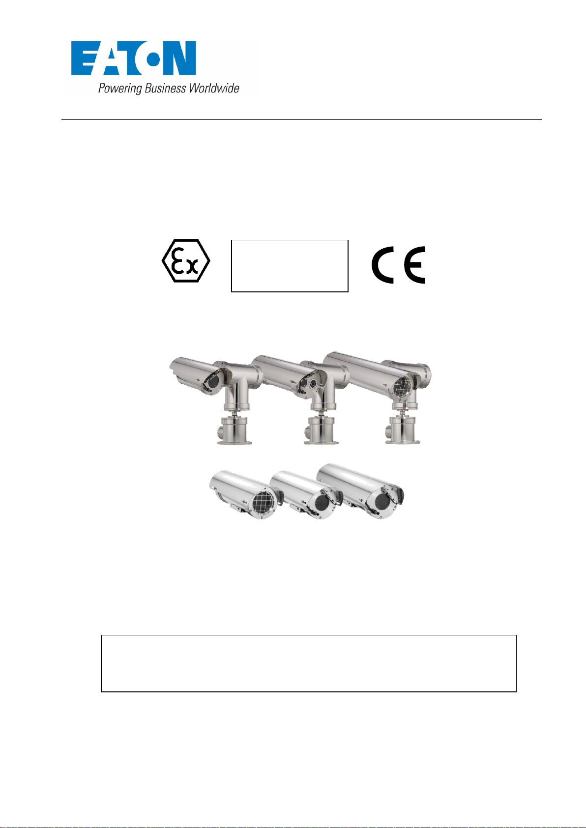
IECEx/ATEX Certified
II 2 G Ex db IIC
II 2 D Ex tb IIIC
Whilst every effort has been made to ensure that all information in this document is correct at the time of
publication, due to our policy of continuous improvement, the company reserves the right to change any
information contained herein without notice or reference.
With the exception to Annexe B which must be referred to the certification Body.
2400 & 1400 Series (XP, XT, XC & XF)
Flame Proof Camera Housings
& Pan Tilt Units
Installation & Maintenance Instructions
This equipment shall be installed in accordance with the latest local/national codes of practice, and standards
This manual should be read before attempting to connect or operate the equipment
eg :- BS EN 60079-14:2014 Explosive atmospheres – Part 14: Electrical installations design, selection and erection
(IEC 60079-14:2013)
Page 2
EATON
Installation & Maintenance Instructions
IMI+70-XF-XC-XP-XT Issue 7
© 2016, Eaton
Page 2 of 21
Issue
Date
Details of Amendment
1.0
First Issue
2.0
09/03/2016
Inclusion of Annexes
3.0
05/04/2016
Inclusion of Ex ia removal of ratings page 5 Additions to
annexe E
4.0
06/04/2016
Change in Harmonised standard issues
5.0
01/09/2016
Change Cert Number, Address, authorised signatory.
Addition of amendment record. Special Conditions.
6.0
13/10/2016
Change in Name and cert labels
7.0
16/11/2016
Removed DOC
Amendment Record
Page 3

EATON
Installation & Maintenance Instructions
IMI+70-XF-XC-XP-XT Issue 7
© 2016, Eaton
Page 3 of 21
Section Page
Amendment Record 3
1.0 General 4
1.1 Important Safeguards and Warnings 4
2.0 Description 5
2.1 Versions 6
2.2 Supplied Equipment 6
2.3 Associated Equipment 6
2.4 Recommended Tools 6
2.5 Recommended Spares 6
3.0 Installation 7
3.1 Unpacking and Handling 7
3.1.1 Unpacking 7
3.1.2 Handling 7
3.2 Mounting 7
3.2.1 Mounting the XP & XT Series 7
3.2.2 Mounting the XC Series 7
3.2.3 Mounting the XF Series 10
3.3 Accessory Installation 11
3.3.1 Sunshield Installation 11
3.3.2 Washer Nozzle Installation 12
3.4 Electrical Installation 13
3.4.1 Electrical Installation XP & XT Integrated Pan, Tilt, housing assembly 13
3.4.2 XP & XT Common Connection Examples 14
3.4.3 Electrical Installation XF & XC Series units 15
3.4.4 XC & XF Common Connection Examples 16
4.0 Maintenance 17
4.1 Corrosion Protection 17
5.0 Labelling 18
5.1 Standard Enclosure label 18
5.2 OP PR Enclosure label 18
5.3 OP IS Enclosure label 18
5.4 [Ex ia] Enclosure label 18
6.0 Specifications, Technical data 19
7.0 Special Conditions for safe use 19
Annexe to Manual
A. Ex Annexe (ATEX Controlled Document) 21-22
Before Installation of the equipment ensure that:
1 The installation instructions are read and understood
2 The correct tools are available for use when installing
Page 4
EATON
Installation & Maintenance Instructions
IMI+70-XF-XC-XP-XT Issue 7
© 2016, Eaton
Page 4 of 21
1.0 General
This symbol indicates that there are important operating and maintenance instructions in the
literature accompanying this unit.
Prior to installation and use of this product, observe the following warnings.
1. Installation and servicing should only be carried out by qualified service personnel and
2. It is essential that provision is made for overload, short circuit and earth fault protection
3. A readily accessible disconnection device shall be incorporated in the electrical
4. Only use tools and replacement parts supplied or recommended by EATON.
5. Care must be taken to ensure selection of suitable cables connecting to these units,
6. The equipment is designed to satisfy the requirements of Clause 1.2.7 of the Essential
7. Be aware that aggressive substances may require extra protection of the equipment to
8. The equipment may need additional means of protection if it is to be installed in
9. Any repairs or replacement parts must be done by the manufacturer or an approved
10. Due to the large weight of the units, correct planning and equipment must be used
11. Systems can be fitted with integral Fibre Optic transmitters, the label coding includes the
12. When batteries are fitted to electronic equipment they must be removed and are not to
13. After installation, operatives must adhere to the following warning on the units label:
14. IR Illuminator “CAUTION Possibly hazardous optical radiation emitted from this
This symbol indicates that dangerous voltage constituting a risk of electric shock may be present
within this unit.
1.1 Important Safeguards and Warnings
in accordance with all local/national codes of practice and standards e.g. EN60079-14
2014 and IEC 60079-14:2013 no modification to the certified product allowed.
for this equipment. Therefore we recommend that a double pole, mains rated,
miniature circuit breaker rated to the max power consumption of the unit, must be
incorporated in the electrical installation of the power supply to this product.
installation wiring, to provide all pole isolation of the supply to the equipment.
This unit does not contain any user serviceable parts.
when installed in operating temperatures above +70°C.
Health and Safety Requirements ANNEX II of ATEX Directive 2014/34/EU.
maintain its integrity and explosion protection.
locations where it may be exposed to excessive external stresses e.g. vibration, heat,
impact and damage.
repair agent.
when unpacking and installing also for the P&T units the correct lifting points must be
adhered to (see section 3.1.2)
lettering “op pr” after Ex d, denoting that the enclosure employs the type of protection
b) protected optical radiation, type of protection “op pr” according to clause 5.1 of
EN60079-28:2015. This means that the fibre optic cabling used has additional protective
measures to ensure that the optical radiation is confined within the cabling, by the use
of a robust conduit covering externally, and Kevlar braided cable inside the conduit and
the enclosure.
be replaced.
product.”
WARNING: DO NOT OPEN WHEN ENERGISED OR WHEN
AN EXPLOSIVE ATMOSPHERE IS PRESENT.
CLEAN WITH DAMP CLOTH.
Page 5
EATON
Installation & Maintenance Instructions
IMI+70-XF-XC-XP-XT Issue 7
© 2016, Eaton
Page 5 of 21
2.0 Description
The 2400 & 1400 series camera assemblies have been developed to meet the rigorous
requirements of Flame proof and dust-ignition-proof electrical equipment for installation and use
in hazardous locations found in the onshore and offshore, oil & gas and petro-chemical
installations. The units may also be used in marine and industrial hazardous environments.
The housing body and all external parts are manufactured entirely of AISI 316L stainless steel for
low maintenance and protection from corrosion.
Each of the main end covers is fixed to the body by five (5), M6 x 16-mm stainless steel hex cap
screws, with the cable entry cover of the XP and XT systems using five M5 x 12-mm stainless
steel hex cap screws; all conforming to the requirements of EN60079-0:2012/IEC 60079-0:2011.
The weatherproof seal of the union between the body and end covers is maintained by use of ‘O’
ring seals fitted in purpose made grooves.
The camera housings feature an internal sliding camera mounting rail which is fitted with an
internal heating element/de-mister, thermostatically controlled, to maintain operating
temperature, and ensure clarity of vision through the window, together with the optional
integral window wiper mechanism.
The viewing window is made with toughened glass, or in the case of the Thermal Imager and
Dual Imager versions, is made from Infra red transparent material and which is factory fitted with
a mechanical window guard.
The mechanical thermal window guard MUST not be removed.
There are four system types that are made up from different combinations of the 2400 and 1400
series certified units; these are:
XF series, fixed camera housings.
XC series, P&T units with integral tilt shaft only.
XP series, P&T units with integral pan and tilt shafts and a fixed base section for cable
connection.
XT series, P&T units with integral pan and tilt shafts and a fixed base section for cable
connection, also a secondary housing for integrated illuminator.
The XF series fixed housings comprise a single tube section with either 3 cable entries in the rear
cover or 1 in the side (model dependant).
The XC series comprise a camera housing fixed to a P&T unit via an integrated tilt shaft; there are
3 cable entries in the rear cover of the housing or 1 into the blank side of the T unit (model
dependant).
The XP and XT units have a single cable entry into the fixed base section, this prevents any
trailing cables.
The 2400 & 1400 series housings and integrated pan/tilt units have been designed and certified
to the ATEX Directive 2014/34/EU and IECEX, with the ratings as detailed in:
Section 6.0 Specifications, Technical data & Special conditions for safe use.
Note: T class and ambient temperature, is dependent on the assembly configuration and
maximum internal power dissipation.
Page 6
EATON
Installation & Maintenance Instructions
IMI+70-XF-XC-XP-XT Issue 7
© 2016, Eaton
Page 6 of 21
2.0 Description (continued)
The project requirements and unit certification label must be checked by the installer before
installation, to confirm that the product supplied is suitable for the intended installation zone
and environment.
Manufactured in accordance with CE & IEC norms
EN 60079-0:2012, EN 60079-1:2014, EN 60079-28:2015 & EN 60079-31:2014, IEC 60079-0:2011,
IEC 60079-1:2013 & IEC 60079-31:2014
2.1 Versions
There are various camera configurations available within the range; these include Day/Night
cameras with optional wiper, integral washer or external washer, Thermal Imager and Dual
Camera Day/Night and Thermal units.
The range also includes options for Standard Analogue Video and Data, HD IP cameras, Hybrid IP
encoders, Digital Fibre optic convertors and Media convertors.
Due to the large variations of possible configurations, this manual only covers the standard
installation of the units.
For detailed connection and configuration of units, the installer should refer to individual project
specific drawings and information.
In addition to this manual there are various addendums available that cover the specific function
of electronics that can be included within the camera assemblies.
2.2 Supplied Equipment
Contained in the package are the following items:
Camera system
Installation/Technical Manual
Optional Sunshield and Fixings
Optional Washer Nozzle Kit
2.4 Recommended Tools
For installation and maintenance purposes, we recommend the following hand tools:
Voltmeter/Ohmmeter
Torque wrench kit Set to 7.5Nm, Hex Allen wrench bits of 5, 4 & 3mm
Spanners 8mm, 10mm & 13mm A/F
Screw drivers standard and Phillips head
Pliers side cutting and long nose
2.5 Recommended Spares
For Maintenance purposes, we recommend the following spares:
OX10-00188 EX Base Cable Entry Seal Kit (50.8x3.53 O-ring + 5x M5x12 A4 socket head screws)
OX10-00190 EX Main Flange Seal Kit (117.07x3.53 O-ring + 5x M6x16 A4 socket head screws)
OX10-00008 WIPPER BLADE ASSEMBLY
OX10-00062 HOUSING WASHER NOZZLE ASSEMBLY
OX10-00063 XP20 CONTINUOUS ROTATION WASHER NOZZLE ASSEMBLY
OX10-00134 XP40 CONTINUOUS ROTATION WASHER NOZZLE ASSEMBLY
Page 7
EATON
Installation & Maintenance Instructions
IMI+70-XF-XC-XP-XT Issue 7
© 2016, Eaton
Page 7 of 21
3.0 Installation
In order to ensure proper wiring and system operation of all components, it is recommended
that all units and all associated control equipment be tested at your Factory before field
installation is attempted.
3.1 Unpacking and Handling
3.1.1 Unpacking
On receipt of the units ensure that the cartons are undamaged and that the contents are all
correct and complete.
After unpacking it is recommended that the packing materials are kept safe in case they are
needed for returning the unit for repair or maintenance.
The protective white film should be removed from sunshields prior to fitting.
3.1.2 Handling
Due to the large weights of the products, correct handling is of great importance.
Lifting into position of P&T units should always be completed using suitable lifting equipment
that is capable of supporting loads in excess of 65Kg. P&T systems should only be lifted using
the T section of the P&T, with equal support on both sides; the camera housing section of the
unit must not be used for lifting. To avoid causing damage to the unit do not rotate by hand.
The units should not be handled having direct contact with ferrous metal equipment. (see
section 4.1 for details)
3.2 Mounting
Ensure the mounting surface and the selected mount can support four times the combined
weight of the complete unit.
Do not stand or place objects “directly under” installed system.
Due care must be taken to ensure sufficient clearance is allowed to permit full rotation of the
unit with its associated equipment mounted and that the moving unit cannot make contact
with personnel.
It is strongly suggested that where possible the EATON range of mounting brackets are used
3.2.1 Mounting the XP & XT Series
The XP and XT pan/tilt/housing assembly may be mounted onto various structures such as
bulkheads, walls or towers, it can be mounted in the inverted position but this must be
specified upon order.
The complete assembly is mounted to the support structure via its base mount which has
11mm clearance holes for four (4) No. M10 fixings. (Fig 1)
The type and size of these fixings to be supplied by the user/installer and must be suitable
for the specific installation requirements.
An alternative is to use the BPW6800 Wall mount bracket (Fig 2)
3.2.2 Mounting the XC Series
The XC pan/tilt/housing assembly may be mounted onto various structures such as bulkheads,
walls or towers, it can be mounted in the inverted position but this must be specified upon
order.
The complete assembly is mounted to the support structure via its Pan shaft and this has four
(4) No. M8 Threaded fixing points on an industry standard spacing PCD of 101.6mm (4”). (Fig 3)
The type and size of these fixings to be supplied by the user/installer and must be suitable for
the specific installation requirements. An alternative is to use the BFW5000 Wall mount
bracket (Fig 4) or one of the BFP**00 Column Spacers. (Fig 5)
Page 8

EATON
Installation & Maintenance Instructions
IMI+70-XF-XC-XP-XT Issue 7
© 2016, Eaton
Page 8 of 21
Fig.1 XP26VW Example XP Series unit showing base mount fixing points
Fig.2 BPW6800 Wall Bracket
Page 9

EATON
Installation & Maintenance Instructions
IMI+70-XF-XC-XP-XT Issue 7
© 2016, Eaton
Page 9 of 21
Fig.3 XC40VW Example XC Series unit showing shaft mount fixing points
Fig.5 BFP0600/900/1200 Column Spacer
Fig.4 BFW5000 Wall Bracket
Page 10

EATON
Installation & Maintenance Instructions
IMI+70-XF-XC-XP-XT Issue 7
© 2016, Eaton
Page 10 of 21
Fig.6 XF60VN Example XF Series unit showing mount plate fixing points
Fig.7 BFP00SW Swivel Joint & Pole Top Adaptor
Fig.8 BFW32SW Swivel Joint & Pole Top Adaptor
3.2.3 Mounting the XF Series
The XF Series fixed housing assemblies may be mounted onto various structures such as
bulkheads, walls or towers. The units have a mounting plate on the bottom of the housing tube
that have
four (4) No. M6 Threaded fixing points. (Fig 6)
The type and size of these fixings to be supplied by the user/installer and must be suitable for
the specific installation requirements.
To gain flexibility of the cameras view direction one of the EATON is needed, these comprise of
the BFP00SW Swivel joint (Fig 7), the BFW32SW (Fig 8) or a combination of the BFW5000 and
BFP00SW. (Figs 4 & 7)
Depending on Housing length, some wall brackets do not allow for the camera to view directly
away from the Wall and must be rotated or tilted to allow room for gland entry.
Page 11

EATON
Installation & Maintenance Instructions
IMI+70-XF-XC-XP-XT Issue 7
© 2016, Eaton
Page 11 of 21
Fig.9 Mid and Long Housing Sunshield Installation
Fig.10 Short Housing Sunshield Installation
3.3 Accessory Installation
3.3.1 Sunshield Installation
Sunshields are supplied uninstalled to prevent damage during shipping and unpacking. They are
supplied with a protective white film that must be removed prior to installation.
The correct sunshield fixings, for each model, are supplied with the camera system and should
be positioned as detailed below.
To mount the sunshields, first they must be positioned correctly and fixed with a Nylon spacer
between the sunshield and the camera housing, the M6 A4 Button head screws supplied must
have the red fibre washer fitted before fixing the sunshield. (Fig 9 & 10)
Long and Medium sunshield have four equally sized fixings for each corner but the short
sunshield has two fixing types, one for the front and shorter screws and nylon spacer at the
rear. (Fig 10)
Page 12

EATON
Installation & Maintenance Instructions
IMI+70-XF-XC-XP-XT Issue 7
© 2016, Eaton
Page 12 of 21
Fig.11 260mm Housing washer nozzle
Fig.12 400mm Housing washer nozzle
Fig.13 Non-continuous Rotation P&Ts and Fixed housings washer nozzle
3.3.2 Washer Nozzle Installation
A continuous rotation P&T system, if supplied with an external washer unit, is supplied with a
suitable washer nozzle and mounting bracket. These should be fitted during installation with
the supplied fixing and positioned to allow cleaning fluid to reach the camera housing window
when the wash command is sent. The supplied washer nozzle brackets are specific to housing
type and are delivered pre-aligned for use.(Fig. 11 & 12)
When a wash command is sent to the camera, the unit will move to the factory set position to
allow for the screen to be washed.
For non-continuous rotation P&Ts and fixed housings the washer nozzle is installed on the front
window flange. (Fig. 13)
Page 13

EATON
Installation & Maintenance Instructions
IMI+70-XF-XC-XP-XT Issue 7
© 2016, Eaton
Page 13 of 21
3.4 Electrical Installation
Electrical installation and servicing should only be carried out by qualified service personnel
and in accordance with all local/national codes of practice and standards e.g. EN 6007914:2014 and IEC 60079-14:2013.
Due to the large variations of possible configurations, this manual only covers the standard
installation of the units.
For detailed connection and configuration of units, the installer should refer to individual
project specific drawings and information.
Units can be supplied, as required, with either 24VAC, 110VAC or 230VAC Supply; all ±10%
The units should only be powered from the specified voltage, no allowance is made for
varying voltage supply.
Warning : Irreparable damage to the unit will result from the application of
incorrect Power Supply Voltage
3.4.1 Electrical Installation XP & XT Integrated Pan, Tilt, housing assembly
1. Always use colour-coded conductors or other identification of conductors for ease
of wiring and identification of function at a later date.
2. Keep a wiring diagram with the system for later use and reference.
3. Provision is made for one cable entry, at the base mount of the pan tilt.(Fig 14)
To maintain the certification requirements of the unit all cables/conduits must be
fitted at the entry, with certified Ex d Flameproof, compound filled barrier glands,
either brass, nickel plated or stainless steel.
4. The cable entry to the unit is M25 x1.5 ISO thread, or M20 using an Exd certified
reducer, dependent on what was specified at order.
5. A minimum of 10 mm depth of engagement must be maintained for all glands.
6. All glands/reducers must be ingress protected to IP67 or better, to maintain the
weatherproof rating of the equipment.
7. For maintenance purposes, consult separately supplied additional wiring drawings
specific to the purchase order, for as built wiring and connection details of the unit.
Page 14

EATON
Installation & Maintenance Instructions
IMI+70-XF-XC-XP-XT Issue 7
© 2016, Eaton
Page 14 of 21
Fig.14 Gaining access to the XP and XT Base junction box
230VAC N
SWITCH L 24VAC
PUMP SUPPLY
DATA A +
DATA B -
N 24VAC
PUMP SUPPLY
EARTH
230VAC L
VIDEO SCREEN
VIDEO SIGNAL
110VAC N
SWITCH L 24VAC
PUMP SUPPLY
DATA A +
DATA B -
N 24VAC
PUMP SUPPLY
110VAC L
VIDEO SCREEN
VIDEO SIGNAL
24VAC N
SWITCH L 24VAC
PUMP SUPPLY
DATA A +
DATA B -
N 24VAC
PUMP SUPPLY
24VAC L
VIDEO SCREEN
VIDEO SIGNAL
230VAC MODEL WITH PUMP OUTPUT
110VAC MODEL WITH PUMP OUTPUT
24VAC MODEL WITH PUMP OUTPUT
230VAC N
DATA A +
DATA B -
230VAC L
VIDEO SCREEN
VIDEO SIGNAL
110VAC N
DATA A +
DATA B -
110VAC L
VIDEO SCREEN
VIDEO SIGNAL
24VAC N
DATA A +
DATA B -
24VAC L
VIDEO SCREEN
VIDEO SIGNAL
230VAC MODEL WITH NO PUMP OUTPUT
110VAC MODEL WITH NO PUMP OUTPUT
24VAC MODEL WITH NO PUMP OUTPUT
NC
EARTH
NC
EARTH
NC
EARTH
EARTH
EARTH
110VAC N
110VAC L
110VAC FIBRE OPTIC MODEL
230VAC N
230VAC L
23VAC IP MODEL
NC
EARTH
EARTH
RJ45 INLINE
CONNECTOR
ETHERNET
VARIOUS FIBRE
BULKHEAD CONNECTORS
FIBRE
Caution should be taken when removing and inserting the cable entry flange to avoid
internal cable becoming snagged on corners or screws.
THE CABLE ENTRY FLANGE SHOULD NEVER BE REMOVED WHEN THE UNIT IS ENERGISED
3.4.2 XP & XT Common Connection Examples
Always refer to project specific drawings and information
Page 15

EATON
Installation & Maintenance Instructions
IMI+70-XF-XC-XP-XT Issue 7
© 2016, Eaton
Page 15 of 21
Fig.15 Removing the Wiper Arm
Fig.16 Removing the Front Window flange
Fig.17 Removing the rear flange
To gain access to the internal camera rail,
first the rail will need to be slid out to allow
connections to be made.
If a wiper is fitted, first take note of the
parked position of the wiper arm and then
remove it by loosening the M4 cap head
screw that clamps to the wiper shaft. Keep
the wiper and nylon washer safe for refitting.
This is best done without the sunshield fitted.
Remove the front window flange by
first removing the 5 x M6 screws
and then carefully extracting the
flange.
Next slide out the camera
mounting rail, if required.
Remove the rear flange by first
removing the 5 x M6 screws
and then carefully extracting
the flange.
Next slide out the camera
mounting rail to reveal the
incoming cable connection
terminals.
3.4.3 Electrical Installation XF & XC Series units
1. Cable entry type to the housing is via 1 x M20 x 1.5 ISO entry at the side adaptor of the
housing, or for some version via the triple M20 cable entry end cover on the rear of the
housing, solely for connection of power and signal wiring, no internal user wiring is
allowed in this unit.(Fig 15, 16 & 17)
2. Keep a wiring diagram with the system for later use and reference.
3. For maintenance purposes, consult separately supplied additional wiring drawings
specific to the purchase order, for as built wiring and connection details of the unit.
Warning : This cover must not under any circumstances be removed until at least 5 minutes
after the disconnection of power source.
Page 16

EATON
Installation & Maintenance Instructions
IMI+70-XF-XC-XP-XT Issue 7
© 2016, Eaton
Page 16 of 21
230VAC N
DATA A +
DATA B -
230VAC L
230VAC MODEL WITH PUMP OUTPUT
NC
EARTH
SWITCH L 24VAC
PUMP SUPPLY
N 24VAC
PUMP SUPPLY
VIDEO DIRECT TO CAMERA
24VAC MODEL WITH PUMP OUTPUT
J1
TH
HEATER
22O 10W
HEATER
22O 10W
J3
J2
24VAC N
DATA A +
DATA B -
24VAC L
NC
EARTH
SWITCH L 24VAC
PUMP SUPPLY
N 24VAC
PUMP SUPPLY
VIDEO DIRECT TO CAMERA
24VAC N
24VAC L
EARTH
DATA A +
DATA B -
24VAC MODEL NO PUMP OUTPUT
J1
TH
HEATER
22O 10W
HEATER
22O 10W
J3
J2
24VAC N
24VAC L
EARTH
24VAC IP MODEL NO PUMP OUTPUT
VIDEO DIRECT TO CAMERA
ETHERNET DIRECTLY TO
CAMERA OR ENCODER
VIA CAT5E, RJ45
3.3.4 XC & XF Common Connection Examples
Always refer to project specific drawings and information
Page 17
EATON
Installation & Maintenance Instructions
IMI+70-XF-XC-XP-XT Issue 7
© 2016, Eaton
Page 17 of 21
4.0 Maintenance
Recommended inspection interval: 6 Months.
Inspect the unit every six months to ensure trouble free operation and extend product life.
Due to the rugged construction of the unit, little or no maintenance should be required.
However when the unit is exposed to extreme weather conditions the ‘O’ ring weather seals
may need replacement approximately every five years.
Fixings and fastenings should be checked for tightness and integrity at regular intervals.
All cable entries and cables should be checked for integrity at regular intervals.
Extremely Harsh Environments may require more frequent inspection and maintenance
checks.
At every Inspection carry out the following:
• Clean the unit.
• Check the ‘O’ ring weather seals and replace if necessary.
• Check and if necessary replace the washer nozzle.
• Check and if necessary replace the window wiper blade assembly.
Please read and be familiar with the instructions before servicing the Pan/Tilt or housing.
4.1 Corrosion Protection
Although all external metal components are produced from 316L Stainless Steel, if the units
are not correctly maintained, handled and cleaned there is the possibility of mild
discolouration due to Oxidation.
If ferrous metal equipment is used when handling the units, small ferrous deposits could be
left on the stainless steel or if ferrous metal particles come to rest upon the units from
nearby works, this can cause accelerated corrosion of the ferrous deposits and discolour the
units due to oxidation. In the event of ferrous deposits, the units should be cleaned
immediately following EATON guidelines.
In atmospheres that are high in corrosive particles the units should be cleaned every 3 to 4
months using only EATON recommended cleaning products and procedures. (contact EATON
for details)
EATON takes no responsibility for oxidisation due to failure in correctly following cleaning
procedures.
Page 18
EATON
Installation & Maintenance Instructions
IMI+70-XF-XC-XP-XT Issue 7
© 2016, Eaton
Page 18 of 21
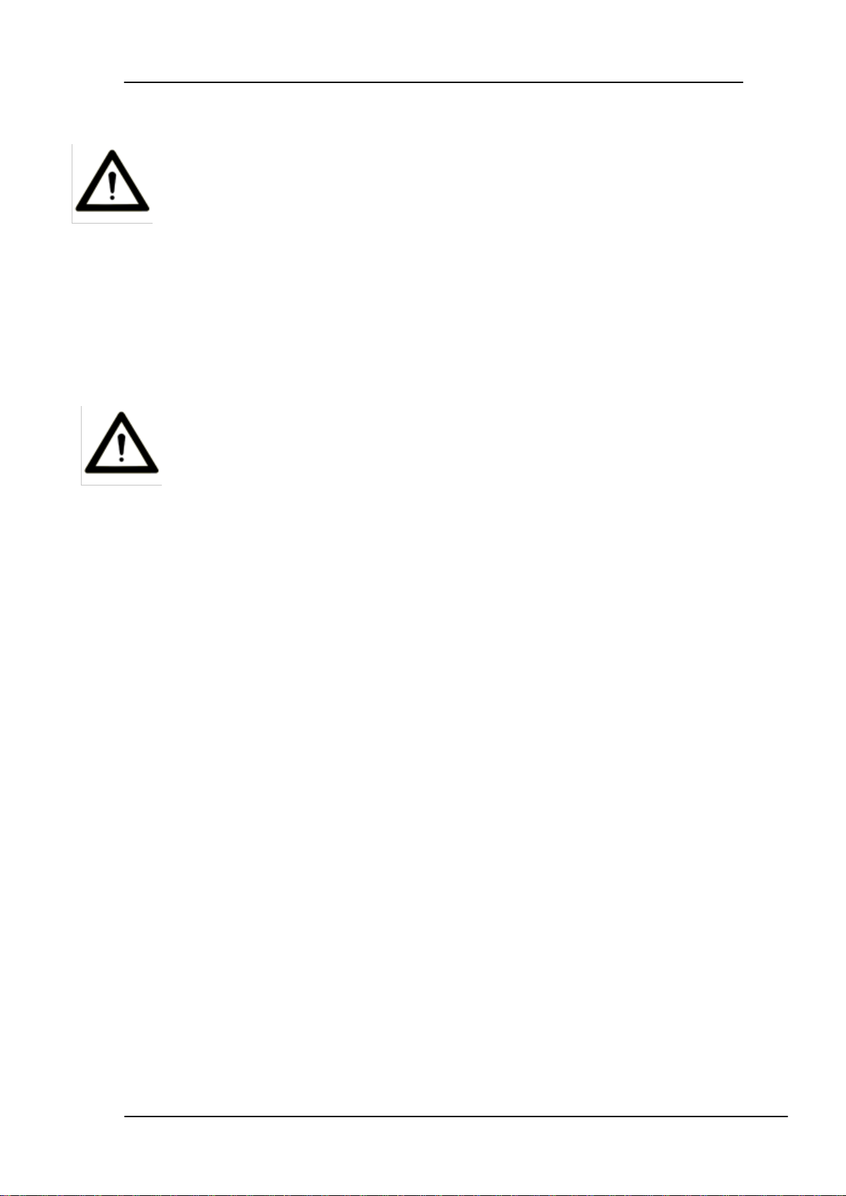
5.0 Labelling
The Labels are printed on self adhesive metalized vinyl and affixed product.
The contents of the label will be in ENGLISH.
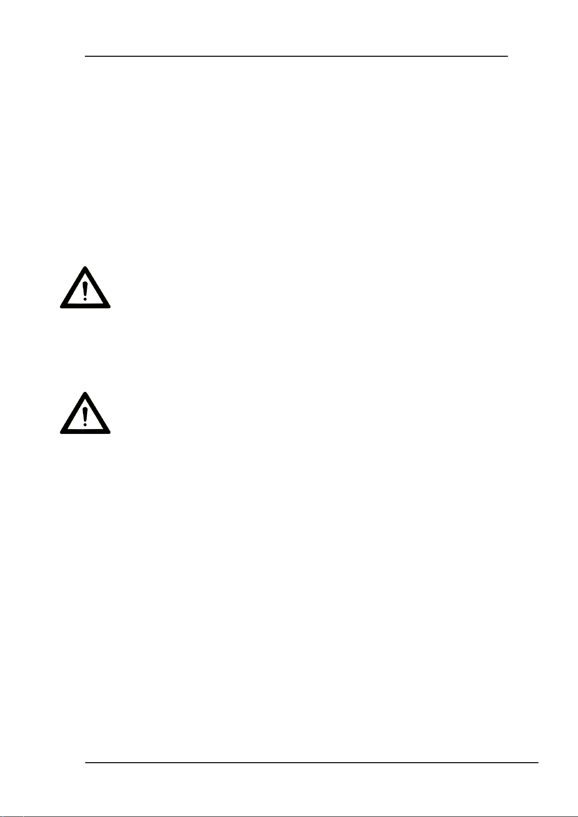
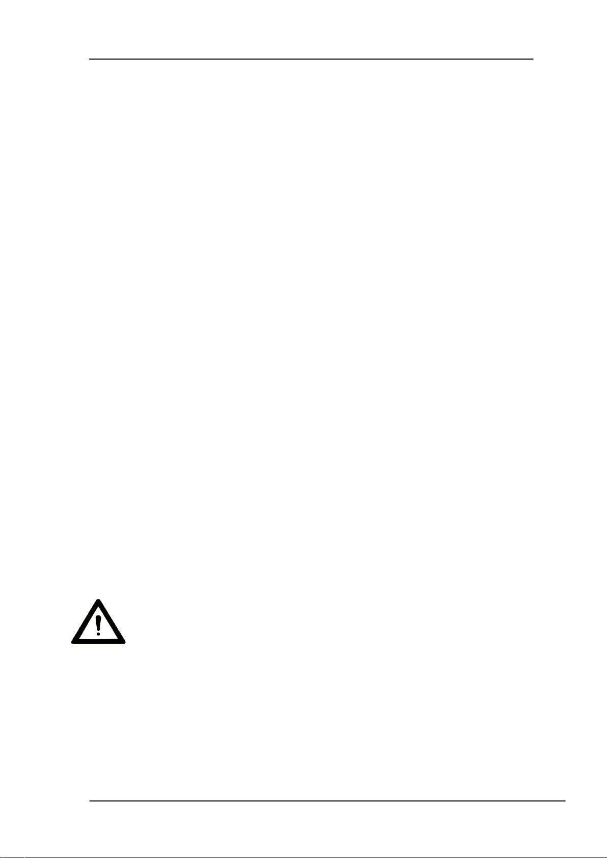
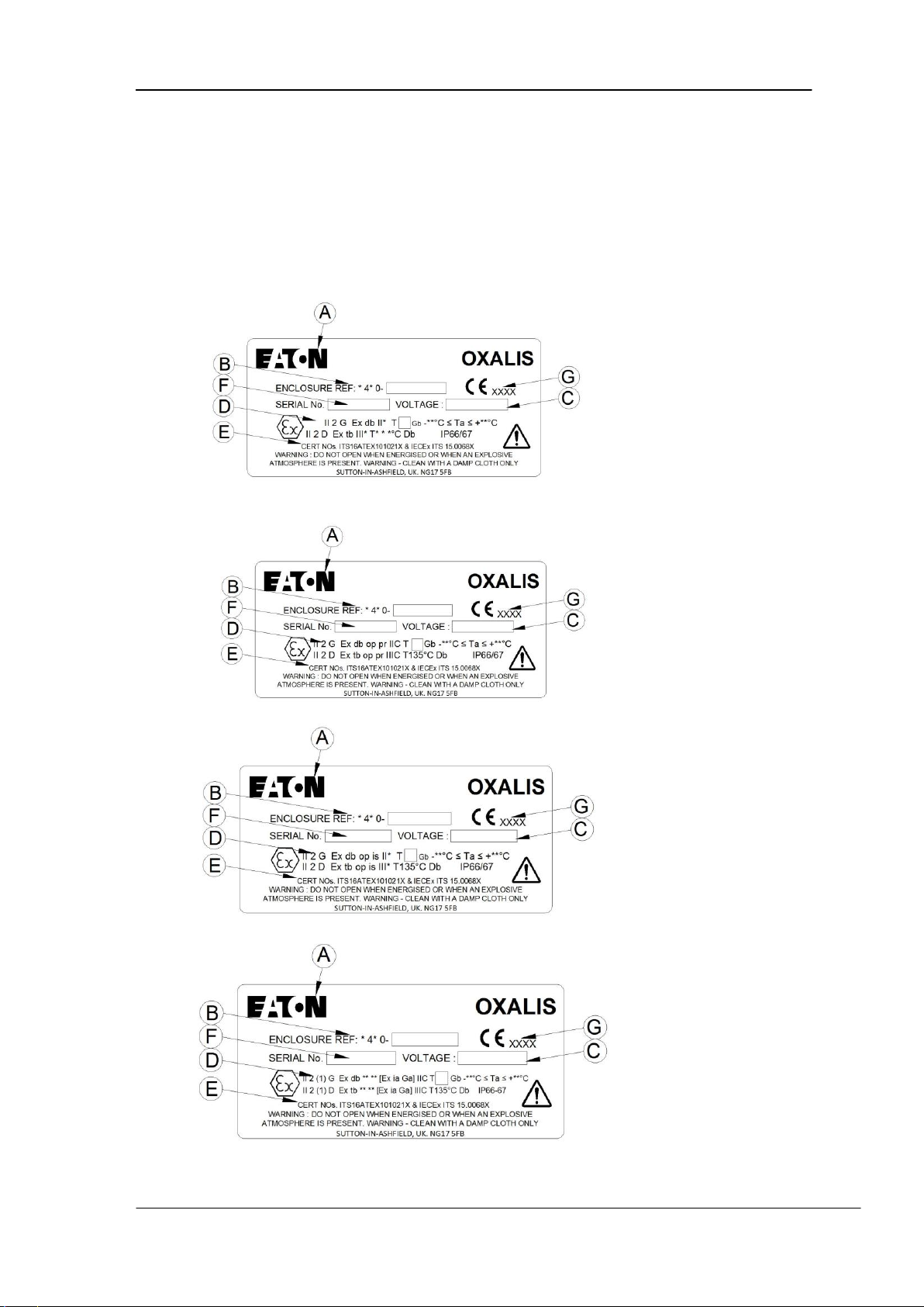
The label shows: A - Name of Manufacturer , B - Model/Type and reference,
C - Operating Voltage,
D - EX ratings, E - ATEX Certificate & IECEX certificate numbers,
F - Serial Number, G - Notified Body Number
5.1 Standard Enclosure label
5.2 OP PR Enclosure label
5.3 OP IS Enclosure label
5.4 [Ex ia Ga] Enclosure label
Page 19

EATON
Installation & Maintenance Instructions
IMI+70-XF-XC-XP-XT Issue 7
© 2016, Eaton
Page 19 of 21
6.0 Specifications, Technical data & Special conditions for safe use.
Coding IECEx & ATEX II 2 G Exdb IIC T6-3*Gb -##°C ≤ Ta ≤ +##°C
II 2 D Ex tb IIIC T135°C Db IP66/67
Illuminator II 2 G Exdb op is IIC T4/3 Gb -##°C ≤ Ta ≤ +##°C
II 2 D Ex tb op is IIIC T135°C Db IP66/67
Fibre Optic II 2 G Exdb op pr IIC T6…3*Gb -##°C ≤ Ta ≤ +##°C
II 2 D Ex tb op pr IIIC T135°C Db IP66/67
Wireless II 2 G Ex db ????[Ex ia Ga] IIC T6…T5 Gb -##°C ≤ Ta ≤ +##°C
II 2 D Ex tb ????[Ex ia Ga] IIIC T135°C Db IP66/67
???? = Optional op pr/op is coding
Note: T class and ambient temperature, is dependent on the assembly configuration and
maximum internal power dissipation.
*=T class, Gas Group
## = Ambient Temperature range
Construction: Stainless Steel AISI 316L
Ingress Protection rating: IP 66/7
Max Weight:
Integrated Pan Tilt with housing : 40-62Kg depending on model
Standalone housing: 12-22Kg depending on model
Mounting:
Integrated Pan Tilt with housing : 4-x M10 fixings on 182mm pcd
Standalone housing: Depending on mounting brackets
Supply voltage: 24VAC, 50/60Hz or
100 to 230VAC with integral transformer
Power consumption: Max 120 Watts depending on model
7.0 Special Conditions for Safe Use.
1. No modifications must be made to the flamepaths of the unit without consultation of the
drawings listed on the schedule.
2. Temperatures could exceed 70°C at the cable gland or 80°C at the branching point,
suitably rated cable must be selected.
3. Use only hex socket head fasteners with property class of A4-70 for securing end covers &
shafts to housings.
4. No electromagnetic or ultrasonic energy radiating equipment shall be fitted within the
enclosures other than armoured/protected fibre optic cables (op pr) or the IR illuminator as
specified in the documents.
5. When fitted the optical fibre output from the camera housing must always be terminated
within a suitably certified enclosure or safe area.
6. Only armoured cable or conduit is to be utilized when fitted with a fibre optic output in
order to protect the fibre optic cable.
7. Precautions must be taken to avoid dust from forming layers on the equipment.
Page 20

EATON
Installation & Maintenance Instructions
IMI+70-XF-XC-XP-XT Issue 7
© 2016, Eaton
Page 20 of 21
A. Ex Annexe
Special Conditions of certification
(a) Specific Conditions for Safe Use.
1. No modifications must be made to the flamepaths of the unit without consultation of the
drawings listed on the schedule.
2. Temperatures could exceed 70°C at the cable gland or 80°C at the branching point, suitably
rated cable must be selected.
3. Use only hex socket head fasteners with property class of A4-70 for securing end covers &
shafts to housings.
4. When fitted, the optical fibre output from the camera must always be terminated within a
suitably certified enclosures or safe area..
5. Only armoured cable or conduit is to be utilized when fitted with a fibre optic output in order
to protect the fibre optic cable.
6. Precautions must be taken to avoid dust from forming layers on the equipment.
7. Antennas used with the equipment shall be passive with nominal impedance of 50Ω and have a
minimum degree of protection IP6X. If the antenna utilizes a wire conductor the minimum
diameter shall be 0.1mm. Alternatively if a track antenna is used, the tracking shall have a
minimum width of 0.4mm
8. The antenna circuit does not meet the dielectric strength requirements of Clause 6.3.13. Refer
to manufacturers’ instruction manual for further details.
Labelling Details.
II 2 G Exdb II* T6-3*Gb -##°C ≤ Ta ≤ +##°C
II 2 D Ex tb III* T135°C Db IP66/67
II 2 G Exdb op is II* T4/3 Gb -##°C ≤ Ta ≤ +##°C (Illuminator)
II 2 D Ex tb op is III* T135°C Db IP66/67
II 2 G Exdb op pr II* T6…3*Gb -##°C ≤ Ta ≤ +##°C (Fibre Optic)
II 2 D Ex tb op pr III* T135°C Db IP66/67
II 2 G Ex db ????[Ex ia Ga] IIC T6…T5 Gb -##°C ≤ Ta ≤ +##°C (Wireless IS)
II 2 D Ex tb ????[Ex ia Ga] IIIC T135°C Db IP66/67
Note: T class, Gas Group and ambient temperature, is dependent on the assembly configuration
and maximum internal power dissipation.
???? = Optional op pr/op is coding
*=T class, Gas Group
## = Ambient Temperature range
Marked Ambient range can be any of the -40C to +40C, -60C to +40C, -40°C to +50°C ,
following -40°C to +55°C , -40C to +70C, -60C to +70C
Wireless Ex ia T6: -40°C ≤ Tamb ≤ +40°C
T5: -40°C ≤ Tamb ≤ +50°C or
T5: -40°C ≤ Tamb ≤ +55°C
Page 21

EATON
Installation & Maintenance Instructions
IMI+70-XF-XC-XP-XT Issue 7
© 2016, Eaton
Page 21 of 21
A. Ex Annexe continued
(b) Conditions of Manufacture, Routine tests,
A routine overpressure test in accordance with IEC 60079-1:2014 Clause 16.1 shall be carried out
on all enclosures, including all cemented window assemblies, at a pressure of 30.12bar for a
period of between 10 and 60 seconds, details must be recorded and records maintained.
There shall be no deformation or damage to the enclosures and no leakage through the cement
of any of the window assemblies integrity of the welded construction shall also be verified during
routine overpressure testing.
Empty enclosures may be tested.
The individual parts of a flameproof enclosure (for example, cover and base) can be tested
separately. The test conditions shall be such that the stresses are comparable to those to which
these parts are exposed in the complete enclosure.
If required during the construction, thread inserts needs to withstand the routine overpressure
test also.
Details must be recorded and records maintained.
WARNING: DO NOT OPEN WHEN ENERGISED OR WHEN AN EXPLOSIVE ATMOSPHERE
IS PRESENT. CLEAN WITH DAMP CLOTH.
 Loading...