

Page 1

IV-3 VFD shield for Arduino
Assembly Manual
October 2014
Page 2

IV-3 VFD shield for Arduino
Table of Contents
1 Overview 3
Features 3
Applications 3
2 Assembly hints 4
3 PCB overview 5
4 Circuit diagram 6
5 Assembly 7
Diodes and IC socket 7
Electrolytic capacitors 7
Ceramic capacitors 8
10K resistors 8
68K resistors 8
220K resistors 9
100K resistors 9
Remaining resistors 9
Arduino headers 10
Power transistors 10
NPN transistors 10
PNP transistors 11
Tube backlighting LEDs 11
VFD tube mounting 12
6 Final test 13
Revision History
Date Authors Description
2014-06-10 Ilse Joostens Initial release.
2014-10-12 Ilse Joostens Second release.
2 Assembly Manual
Page 3

IV-3 VFD shield for Arduino
1 Overview
This Arduino shield is capable of driving 4
Russian IV-3 7 segment VFD tubes. 4
3mm LEDs provide background lighting for
the tubes.
The design is completely based on through
hole components, no SMD components
were used. As such, the PCB can easily be
assembled by anyone who has some
soldering experience.
Also, the components used are cheap and
easily available.
As this was designed as a more
educational, easy to build project it is not
the best possible solution to drive these VFD tubes from a technical point of view.
Instead of the BC547 and BC557 transistors we could have used A2982W source drivers,
or we could have replaced the transistors by a Supertex high voltage source driver IC
with internal shift register. Unfortunately these may be hard to get and come very often
in SMD packages.
Features
• Compatible with Arduino boards.
• Drives 4 IV-3 VFD tubes.
• Power supply 12V DC + 5V DC (via Arduino board, 12V supply needs to be
stabilized).
• Enclosure design (CAD files) available.
Applications
• Clock.
• Score board.
• Thermometer.
• Counter.
Assembly Manual 3
Page 4

IV-3 VFD shield for Arduino
2 Assembly hints
This kit is designed for someone who has advanced experience with assembling
electronics. If you believe that the kit is too complicated for your skill level please do not
try to assemble it
Take your time - this kit should take 2-3 hours to complete if uninterrupted.
Ensure your work area is well lit (daylight preferred) and clean.
Assemble the board in the order as stated in the instructions - read and understand each
step before you perform each operation.
It is assumed that you understand that semiconductors (diodes, ICs, transistors) or
electrolytic capacitors are polarized components. Appropriate markings are silk-screened
on the PCB and shown on the board schematic.
The following tools and materials will be required to assemble the PCB:
• A good quality soldering iron (25-40W) with a small tip (1-2 mm)
• Wire cutter and pliers
• Basic multimeter for voltage tests and for identifying the resistors.
• A magnifying glass to read the small device markings is often helpful.
• Solder – lead / tin solder is preferred. Lead free solder, as now required to be
used in commercial products in Europe, has a much higher melting point and can
be very hard to work with. Do not use any flux or grease.
• Desoldering wick (braid) can be useful if you accidentally create solder bridges
between adjacent solder joints.
Power supply
The IV-3 VFD shield needs the Arduino to be powered from a 12 V DC power supply to
function properly. Use only a regulated switching power adapter capable of delivering 12
V DC / 300 mA.
Do not use an unregulated "transformer style" wall adapter. These deliver
easily more than 16 V with a light load and will cause damage to the IV-3 VFD
shield as the 12 V supply voltage is quite critical.
Put some insulating tape on the metal shield of the USB connector of your
Arduino before connecting the IV-3 shield to avoid solder connections touching
the metal and being shorted.
4 Assembly Manual
Page 5

IV-3 VFD shield for Arduino
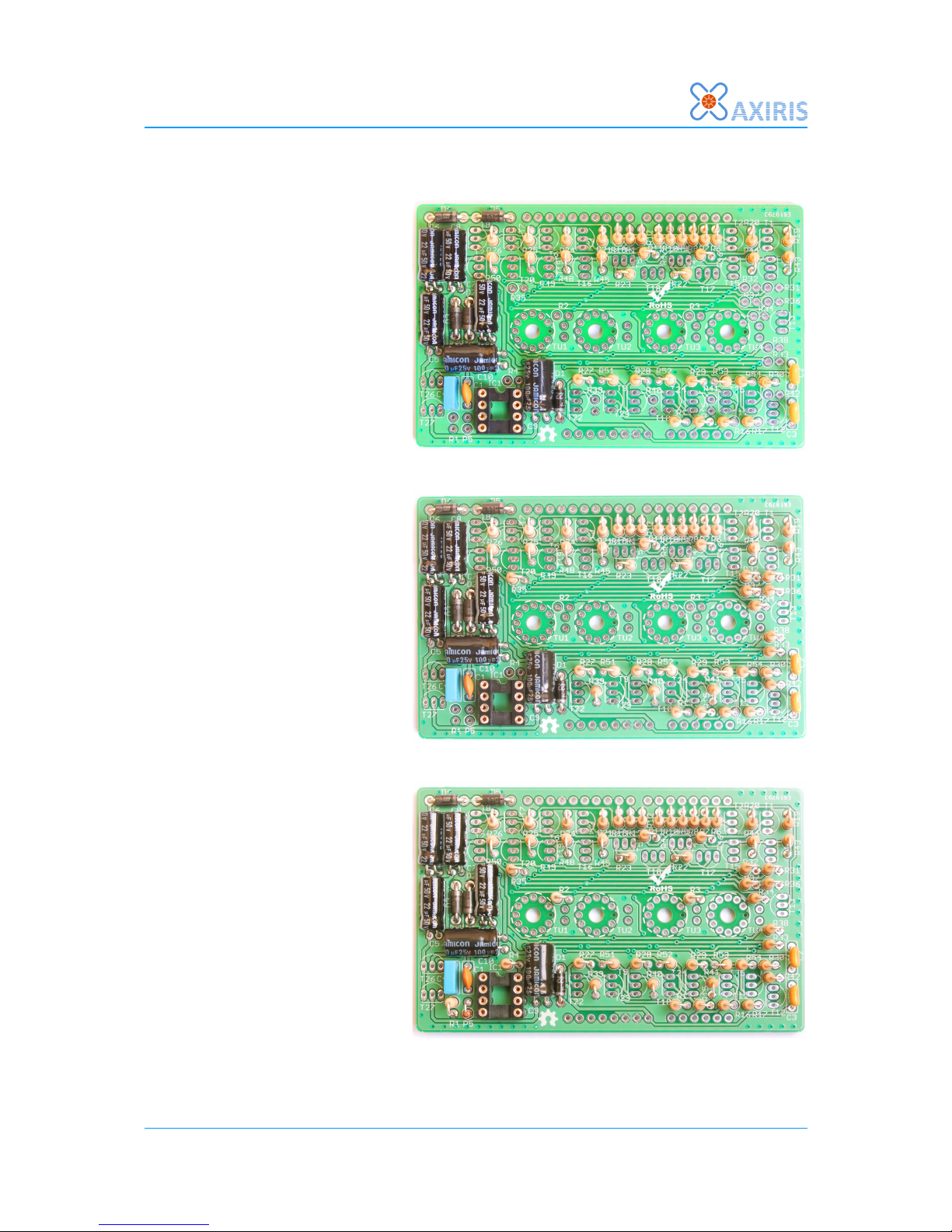
3 PCB overview
Assembly Manual 5
Page 6

IV-3 VFD shield for Arduino
4 Circuit diagram
6 Assembly Manual
Page 7

IV-3 VFD shield for Arduino
5 Assembly
In the following pages we are going to assemble the PCB step by step. It may be helpful
to keep the PCB overview and the circuit diagram at hand during assembly.
After every step, carefully compare your PCB with the pictures in the manual and check
for errors and solder faults.
Diodes and IC socket
Mount the following diodes:
• D1: 1N400x or equivalent
• D2...D5: 1N5819 schottky
diode
Watch the polarity and be careful
to mount the right diode in the
right place.
Solder D2 and D3 from the
component side and trim the
wires on the solder side as short
as possible as they are positioned
above the metal USB connector
shielding of the arduino.
Mount the 8 pole IC socket for IC1. Do not place IC1 in the socket at this stage.
Electrolytic capacitors
Mount the following electrolytic
capacitors:
• C5...C8: 22µF 50V radial
electrolytic capacitor
• C9, C10: 100µF 25V radial
capacitor
Bend the leads 90 degrees and
mount the capacitors flush to the
PCB. Watch the polarity.
It is recommended to solder C6,
C7 and C8 from the component
side and to trim the leads as short
as possible on the solder side as
they are positioned above the metal shield of the Arduino USB connector.
Assembly Manual 7
Page 8

IV-3 VFD shield for Arduino
Ceramic capacitors
Mount the following ceramic
capacitors:
• C1: 2n2
• C2, C3: 8n2
• C4: 100n
Please note that the values of
C1...C3 are somewhat critical as
C1 defines together with R5 the
operating frequency of the voltage
tripler and C2, C3 define the
filament current for the IV-3
tubes.
10K resistors
Mount the 10 kilo ohm resistors
(brown – black – orange – gold)
R6...R18.
Mount them vertically as in the
picture.
68K resistors
Mount the 68 kilo ohm resistors
(blue – grey – orange – gold)
R19...R30.
Mount them vertically as in the
picture.
8 Assembly Manual
Page 9
IV-3 VFD shield for Arduino
220K resistors
Mount the 220 kilo ohm resistors
(red – red – yellow – gold)
R43...R54.
Mount them vertically as in the
picture.
100K resistors
Mount the 100 kilo ohm resistors
(brown – black – yellow – gold)
R31...R42.
Mount them vertically as in the
picture.
Remaining resistors
Mount the remaining resistors:
• R1: 510 ohm (green –
brown – brown – gold)
• R2, R3: 1 kilo ohm (brown
– black – red – gold). You
may need to adjust the
value depending on the
tube backlight LEDs you
plan to use.
• R4: 2.7 kilo ohm (red –
violet – red – gold)
• R5: 3.9 kilo ohm (orange –
white – red – gold)
Assembly Manual 9
Page 10

IV-3 VFD shield for Arduino
Arduino headers
Mount the Arduino stackable
headers. The headers will not
really be used to stack other
Arduino shields on top of this
shield but they help to determine
the mounting height of several
components and the IV-3 tubes.
Push the headers through the PCB
and plug them in your Arduino.
Turn upside down and solder 1-2
pins for each connector. So the
connector spacing will be correct.
Remove the shield from the
Arduino and solder the remaining
pins.
Power transistors
Mount the following transistors:
• T26: BC639
• T27: BC640
Do not replace these transistors
with standard types. Mount them
so that the top of their housings is
lower than the Arduino headers.
Insert IC1 ICM7555 into its socket
and plug the shield into an
Arduino and apply power. The
voltage measured between the
cathode of D5 and the Arduino
ground should be around 32...34V
NPN transistors
Mount the BC547B transistors T1
… T13.
Mount them so that the top of
their housings stays below (or is
flush with) the Arduino headers.
10 Assembly Manual
Page 11

IV-3 VFD shield for Arduino
PNP transistors
Mount the BC557B transistors T14
… T25.
Mount them so that the top of
their housings stays below (or is
flush with) the Arduino headers.
Tube backlighting LEDs
You can use 3mm standard LEDs
in any color for tube backlighting
purposes, even RGB color fading
LEDs.
Bend the leads of the LEDs so that
the LEDs fit in the 3mm holes
underneath the VFD tubes, then
solder them to the pcb. Pay
attention to polarity. The short
lead of the LED (cathode) is
soldered to the pad closest to the
LED name silk-screen marking
(D6 … D8).
It may be necessary to insulate
the leads of D9 to avoid them
touching the ISP connector on the
Arduino.
The LEDs are connected to a PWM
output on the Arduino and can be
dimmed using software. This will
however not work properly when
you use RGB color fading LEDs.
If it is easier for you, it is also
possible to mount the LEDs after
the VFD tubes are soldered in
place. Due to the mounting
technique, it is also easy to
replace the LEDs later on if you
decide you would like to have another backlighting color.
Assembly Manual 11
Page 12

IV-3 VFD shield for Arduino
VFD tube mounting
Guide the tube wires gently
through their respective holes on
the PCB. Make sure the short lead
on the tubes goes through the
hole without solder pad.
Now the digits should face the
front of the PCB.
If you have difficulties getting the
wires of the tubes through the
holes you can cut them as a
"spiral" so you can move 1 wire at
a time through the holes. Pay
attention to make the shortest
wire not too short as we are going
to mount the tubes with some
distance from the pcb.
Once the tubes are in place align
them more or less by hand. The
bottom of the tubes should be
approximately 1-2 mm below the
top of the Arduino stackable
headers.
If you are using the optional
acrylic enclosure, you can use the
top and bottom plates as an
alignment tool.
Solder two leads of each tube to
the PCB. Once this is done, you
can still adjust the tube alignment
by reheating the solder joints.
If you are satisfied with the tube
alignment, you can finally solder
the remaining tube wires in place
and trim the excess leads with a
small wire cutter.
Do not try to change the
alignment of a tube after it is
soldered in place as this may
cause mechanical stress and
may lead to a defective tube.
12 Assembly Manual
Page 13

IV-3 VFD shield for Arduino
6 Final test
Upload the demo sketch from the
Axiris website to the Arduino and
disconnect the Arduino from the
computer's USB port.
Plug the finished IV-3 VFD shield
on top of the Arduino. Make sure
no metal part of the Arduino
touches the solder joints of the
IV-3 VFD shield.
Connect the 12 V DC power
adapter to the Arduino power
connector and turn the power on.
After a few seconds the VFD tubes
should start counting from 0 to 9
in an endless loop. The decimal
separator dots of the VFD tubes
should form a binary 4 bit counter.
Tube backlighting should dim
every few seconds and turn on
again.
Check the tube filament wires
carefully. They should glow very
faintly with a deep red color. If
they are glowing too much, lower
the values of C2 and C3. On the
other hand, if the filament barely
glows and the digits are too dim,
you can experiment by increasing
the values for C2 and C3.
Assembly Manual 13
 Loading...