

Page 1

tBOX311-820-FL Series
Embedded System
User’s Manual
i
Page 2

ii
Disclaimers
This manual has been carefully checked and believed to contain
accurate information. Axiomtek Co., Ltd. assumes no responsibility for
any infringements of patents or any third party’s rights, and any liability
arising from such use.
Axiomtek does not warrant or assume any legal liability or
responsibility for the accuracy, completeness or usefulness of any
information in this document. Axiomtek does not make any
commitment to update the information in this manual.
Axiomtek reserves the right to change or revise this document and/or
product at any time without notice.
No part of this document may be reproduced, stored in a retrieval
system, or transmitted, in any form or by any means, electronic,
mechanical, photocopying, recording, or otherwise, without the prior
written permission of Axiomtek Co., Ltd.
Copyright 2012 Axiomtek Co., Ltd.
All Rights Reserved
March 2012, Version A1
Printed in Taiwan
Introduction
Page 3

iii
Safety Precautions
Before getting started, please read the following important safety
precautions.
1. User should not modify any unmentioned jumper setting
without Axiomtek FAE’s instruction. Any modification without
instruction might cause system to become damage
2. The tBOX311-820-FL does not come equipped with an
operating system. An operating system must be loaded first
before installing any software into the computer.
3. Be sure to ground yourself to prevent static charge when
installing the internal components. Use a grounding wrist
strap and place all electronic components in any staticshielded devices. Most electronic components are sensitive
to static electrical charge.
4. Disconnect the power cord from the tBOX311-820-FL before
making any installation. Be sure both the system and the
external devices are turned OFF. Sudden surge of power
could ruin sensitive components. Make sure the tBOX311820-FL is properly grounded.
5. Make sure the voltage of the power source is correct before
connecting the equipment to the power outlet.
6. Turn OFF the system power before cleaning. Clean the
system using a cloth only. Do not spray any liquid cleaner
directly onto the screen.
7. Do not leave this equipment in an uncontrolled environment
where the storage temperature is below -40℃ or above 80℃.
It may damage the equipment.
8. Do not open the system’s back cover. If opening the cover for
maintenance is a must, only a trained technician is allowed to
do so. Integrated circuits on computer boards are sensitive to
static electricity. To avoid damaging chips from electrostatic
discharge, observe the following precautions:
Before handling a board or integrated circuit, touch an
unpainted portion of the system unit chassis for a few
seconds. This will help to discharge any static electricity
on your body.
When handling boards and components, wear a wrist-
grounding strap, available from most electronic
component stores.
Page 4

iv
Classification
1. Degree of production against electric shock: not classified
2. Degree of protection against the ingress of water: IP40
3. Equipment not suitable for use in the presence of a
flammable anesthetic mixture with air or with oxygen or
nitrous oxide.
4. Mode of operation: Continuous
General Cleaning Tips
You may need the following precautions before you begin to clean the
computer. When you clean any single part or component for the
computer, please read and understand the details below fully.
When you need to clean the device, please rub it with a piece of dry
cloth.
1. Be cautious of the tiny removable components when you use
a vacuum cleaner to absorb the dirt on the floor.
2. Turn the system off before you start to clean up the
component or computer.
3. Never drop the components inside the computer or get circuit
board damp or wet.
4. Be cautious of all kinds of cleaning solvents or chemicals
when you use it for the sake of cleaning. Some individuals
may be allergic to the ingredients.
5. Try not to put any food, drink or cigarette around the
computer.
Introduction
Page 5

v
Cleaning Tools:
Although many companies have created products to help improve the
process of cleaning your computer and peripherals users can also use
household items to clean their computers and peripherals. Below is a
listing of items you may need or want to use while cleaning your
computer or computer peripherals.
Keep in mind that some components in your computer may only be
able to be cleaned using a product designed for cleaning that
component, if this is the case it will be mentioned in the cleaning.
Cloth: A piece of cloth is the best tool to use when rubbing up
a component. Although paper towels or tissues can be used
on most hardware as well, we still recommend you to rub it
with a piece of cloth.
Water or rubbing alcohol: You may moisten a piece of cloth a
bit with some water or rubbing alcohol and rub it on the
computer. Unknown solvents may be harmful to the plastics
parts.
Vacuum cleaner: Absorb the dust, dirt, hair, cigarette particles,
and other particles out of a computer can be one of the best
methods of cleaning a computer. Over time these items can
restrict the airflow in a computer and cause circuitry to
corrode.
Cotton swabs: Cotton swaps moistened with rubbing alcohol
or water are excellent tools for wiping hard to reach areas in
your keyboard, mouse, and other locations.
Foam swabs: Whenever possible it is better to use lint free
swabs such as foam swabs.
NOTE: We strongly recommended that you should shut down
the system before you start to clean any single
components.
Please follow the steps below:
1. Close all application programs
2. Close operating software
3. Turn off power switch
4. Remove all device
5. Pull out power cable
Page 6

vi
Scrap Computer Recycling
If the computer equipments need the maintenance or are beyond
repair, we strongly recommended that you should inform your
Axiomtek distributor as soon as possible for the suitable solution. For
the computers that are no longer useful or no longer working well,
please contact your Axiomtek distributor for recycling and we will
make the proper arrangement.
Trademarks Acknowledgments
Axiomtek is a trademark of Axiomtek Co., Ltd.
Windows® is a trademark of Microsoft Corporation.
AMI® is a registered trademark of American Megatrends Inc.
IBM, PC/AT, PS/2, VGA are trademarks of International Business
Machines Corporation.
Intel® and Atom™ are trademarks of Intel Corporation.
Winbond is a trademark of Winbond Electronics Corp.
Other brand names and trademarks are the properties and registered
brands of their respective owners.
Introduction
Page 7

vii
Table of Contents
Disclaimers ......................................................................................... ii
Safety Precautions ............................................................................. iii
Classification ...................................................................................... iv
CHAPTER 1 INTRODUCTION .......................................................... 1
1.1 General Description ................................................................. 1
1.2 System Specifications ............................................................. 3
1.2.1 CPU ............................................................................. 3
1.2.2 System I/O .................................................................. 3
1.2.3 System Specification ................................................... 4
1.2.4 Driver CD Content ....................................................... 5
1.3 Dimensions .............................................................................. 6
1.4 I/O Outlets ............................................................................... 7
1.5 Packing List ............................................................................. 9
CHAPTER 2 HARDWARE INSTALLATION ................................... 11
2.1 HDD and CF card Installation ................................................ 11
2.2 Installing the SIM Card and Express Mini Card. ................... 14
CHAPTER 3 CONNECTORS .......................................................... 17
3.1 VGA Connector ........................................................ 18
3.2 Serial Port Connector ................................................ 18
3.3 Audio Phone Jack Connector ................................... 19
3.4 USB2.0 Stack Ports .................................................. 19
3.5 LED Indicators........................................................... 20
3.6 CANBUS connector .................................................. 20
3.7 DC Power Input connector ........................................ 21
3.8 LAN Connector (LAN1, LAN2) .................................. 21
3.9 Digital I/O Connector ................................................. 22
3.10 SIM Card Connector ................................................. 23
3.11 PCI-Express Mini Card Connector(SCN4,5,6) ......... 23
3.12 CompactFlash™ Socket ........................................... 25
3.13 SATA Connector ....................................................... 27
3.14 SATA Power Connector ............................................ 27
CHAPTER 4 PHOENIX-AWARD BIOS UTILITY ............................ 29
4.1 Entering Setup .......................................................... 29
Page 8

viii
4.2 Control Keys .............................................................. 29
4.3 Getting Help .............................................................. 30
4.4 The Main Menu ......................................................... 31
4.5 Standard CMOS Setup Menu ................................... 32
4.6 Advanced BIOS Features ......................................... 34
4.7 Advanced Chipset Features ...................................... 41
4.8 Integrated Peripherals ............................................... 44
4.10 PnP/PCI Configuration Setup .................................... 54
4.11 PC Health Status ....................................................... 60
4.12 Load Optimized Defaults ........................................... 61
4.13 Set Supervisor/User Password ................................. 62
4.14 Save & Exit Setup ..................................................... 64
4.15 Exit Without Saving ................................................... 65
APPENDIX A WATCHDOG TIMER ................................................ 67
APPENDIX B DIGITAL I/O .............................................................. 71
APPENDIX C DIGITAL I/O Wiring ................................................. 73
APPENDIX D Power On Procedure .............................................. 77
1 Introduction ............................................................... 77
2 Power Input Mode Setting ......................................... 78
3 DC-inlet Introduction ................................................. 79
4 Power on cabling example ........................................ 80
Introduction
Page 9

tBOX311-820-FL Series User’s Manual
1
CHAPTER 1
INTRODUCTION
This chapter contains general information and detailed specifications
of the tBOX311-820-FL. The Chapter 1 includes the following sections:
General Description
System Specification
Dimensions
I/O Outlets
Package List
1.1 General Description
The tBOX311-820-FL is an embedded system that supports onboard
Intel® Atom™ processor Z520PT (1.33 GHz), to provide Windows®
XPE, Windows® XP, Windows® CE embedded and Linux, suitable for
the most endurable operation. It features fanless design with full
feature I/O, supports High performance DDR2-667 SODIMM, and
enhanced system dependability by built-in Watchdog Timer.
Features
1. Intel® Atom™ processor Z520PT (1.33 GHz) onboard
2. Intel® US15WPT chipset
3. Fanless operation
4. Operatin temperature range of -40°C ~ +65°C
5. 1 isolated RS-232/422/485 and 1 isolated CAN
bus(optional for RS-232)
6. High performance DDR2-667 SODIMM max. up to 2 GB
7. One 2.5" swappable SATA drive bay and one
CompactFlash™ slot
8. 3 internal PCI Express Mini Card slots with one SIM slot
Introduction
Page 10

tBOX311-820-FL Series User’s Manual
2
Reliable and Stable Design
The tBOX311-820-FL adopts the advanced cooling system
and supporting the CompactFlash™, which makes it
especially suitable for vibration environments, best for
transportation applications.
Embedded O.S. Supported
The tBOX311-820-FL not only supports Windows® XP, but
also supports embedded OS, such as Windows® XP
embedded, WinCE and Linux. For storage device, the
tBOX311-820-FL supports one 2.5" SATA HDD drive bays,
and one CompactFlash™ type II slot.
Introduction
Page 11

tBOX311-820-FL Series User’s Manual
3
1.2 System Specifications
1.2.1 CPU
CPU
Onboard Intel® Atom™ processor Z520PT (1.33 GHz)
BIOS
Phoenix AwardBIOS.
System Memory
One 200-pin SO-DIMM support DDR2 400/533MHz
max. up to 2GB
Graphics
Intel GMA500 graphics Core integrate in US15W PT
1.2.2 System I/O
1 x isolated RS-232/422/485 (COM 1)
1 x isolated CAN bus (optional 1 x RS-232)
2 x VGA
1 x Audio (Mic-in/Line-out)
2 x 10/100/1000Mbps Ethernet
4 x USB 2.0
1 x VDC power input connector
1 x DI/DO power input connector (4-IN/4-OUT)
1 x dry/wet switch
1 x 12V/24V switch
1 x reset switch
3 x antenna opening
Introduction
Page 12

tBOX311-820-FL Series User’s Manual
4
1.2.3 System Specification
Watchdog Timer
Reset supported; 255 levels, 1~255 sec.
Power Supply
DC12V mode:
Operating voltage: DC9 ~ 16V
Start voltage: DC12V or higher
DC24V mode:
Operating voltage: DC18 ~ 32V
Start voltage: DC24V or higher
Operation Temperature
-40°C~ +65°C (-40°F ~ +149°F)
Storage Temperature
-40°C ~ +80°C (-4°F ~ +176°F)
Humidity
10% ~ 90% (non-condensation)
Vibration Endurance
2Grms w/ CF (5 ~ 500Hz, X, Y, Z directions)
Weight
2.5 kg (5.5 lb) without package
3.5 kg (7.7 lb) with package
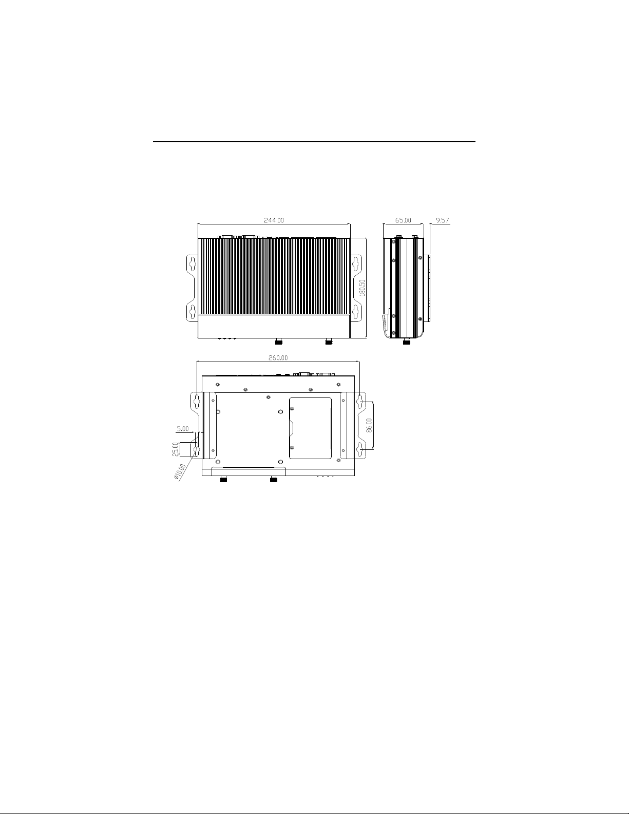
Dimensions
244mm(9.6")(W)x185.4mm (7.3")(D)x70.4mm (2.77")(H)
NOTE: All specifications and images are subject to change without
notice.
Introduction
Page 13

tBOX311-820-FL Series User’s Manual
5
1.2.4 Driver CD Content
Chipset Driver
Graphic Drivers
Audio Drivers
Ethernet Driver
User Manual
Quick Manual
CANBUS Command User Manual
CANBUS Programmer’s Guide
CANBUS Library
AXCAN CANBUS diagnostic tool
Introduction
Page 14
tBOX311-820-FL Series User’s Manual
6
1.3 Dimensions
The following diagrams show you dimensions and outlines of
the tBOX311-820-FL.
Introduction
Page 15
tBOX311-820-FL Series User’s Manual
7
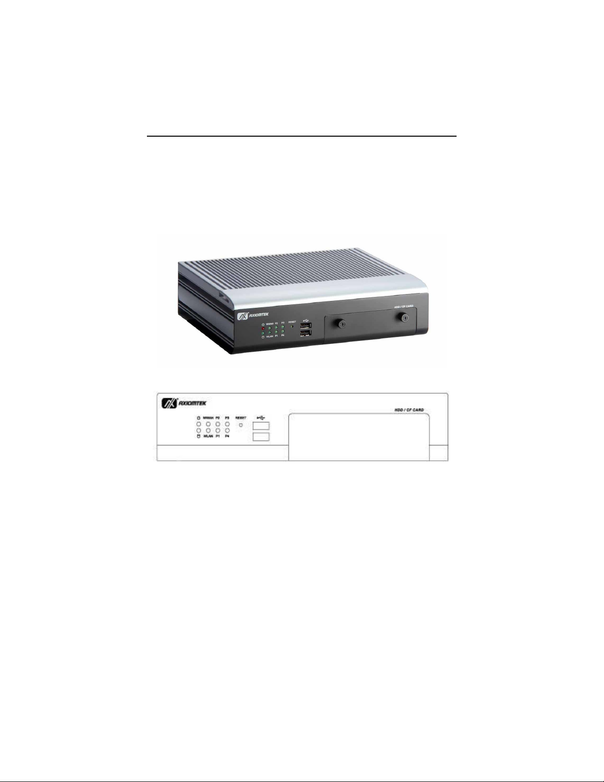
1.4 I/O Outlets
The following figures show you I/O outlets on front view of the
tBOX311-820-FL.
Front View
Front View drawing
Introduction
Page 16

tBOX311-820-FL Series User’s Manual
8
Rear View
Rear View drawing
CANBUS
COM
Introduction
Page 17

tBOX311-820-FL Series User’s Manual
9
1.5 Packing List
The package bundled with your tBOX311-820-FL should
contain the following items:
tBOX311-820-FL System Unit x 1
tBOX311-820-FL Quick Manual x 1
CD x 1 (For Driver and User’s Manual)
Screws pack
Foot pad x4
Wall-mount Brackets
DIO female connector
HDD (optional)
CF (optional)
Antenna (optional)
Express Mini Card Module (optional, installed or non-installed)
SMA cable (optional)
If you can not find this package or any items are missing, please
contact Axiomtek distributors immediately.
Introduction
Page 18

tBOX311-820-FL Series User’s Manual
10
MEMO:
Introduction
Page 19

tBOX311-820-FL Series User’s Manual
11
CHAPTER 2
HARDWARE INSTALLATION
The tBOX311-820-FL is convenient for your various hardware
configurations, such as HDD (Hard Disk Drive), CompactFlashTM card
and Express Mini Card. The chapter 2 will show you how to install the
hardware.
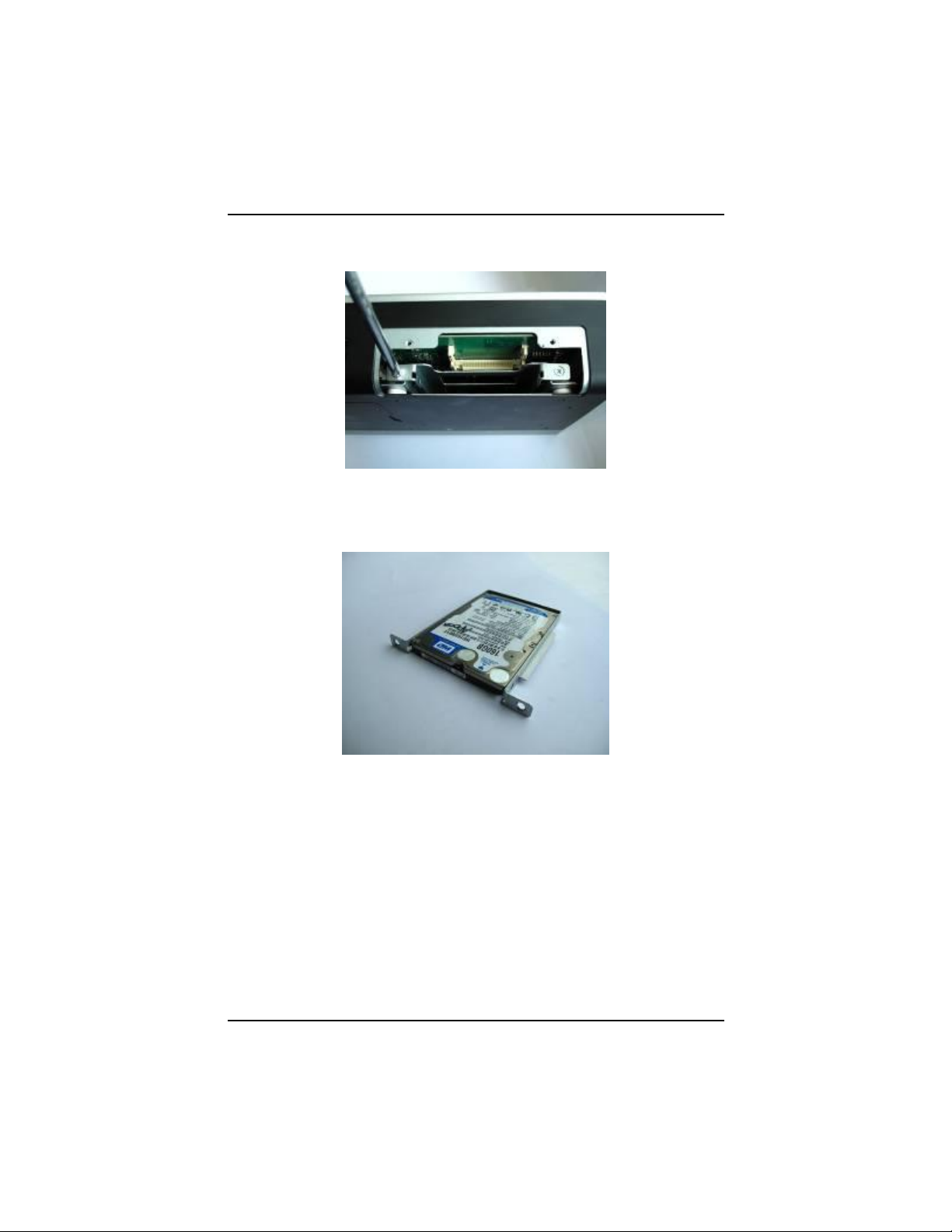
2.1 HDD and CF card Installation
Step 1) Turn off the system, and unplug the power cord. Locate
thumbscrew at the front side, loosen screws.
Step 2) Slide CF card into CF slot carefully.
Hardware Installation
Page 20
tBOX311-820-FL Series User’s Manual
12
Step 3) Loosen screws of HDD bracket.
Step 4) Stick the HDD handhold malar with HDD, assembly the
HDD bracket together with the SATA HDD
Hardware Installation
Page 21
tBOX311-820-FL Series User’s Manual
13
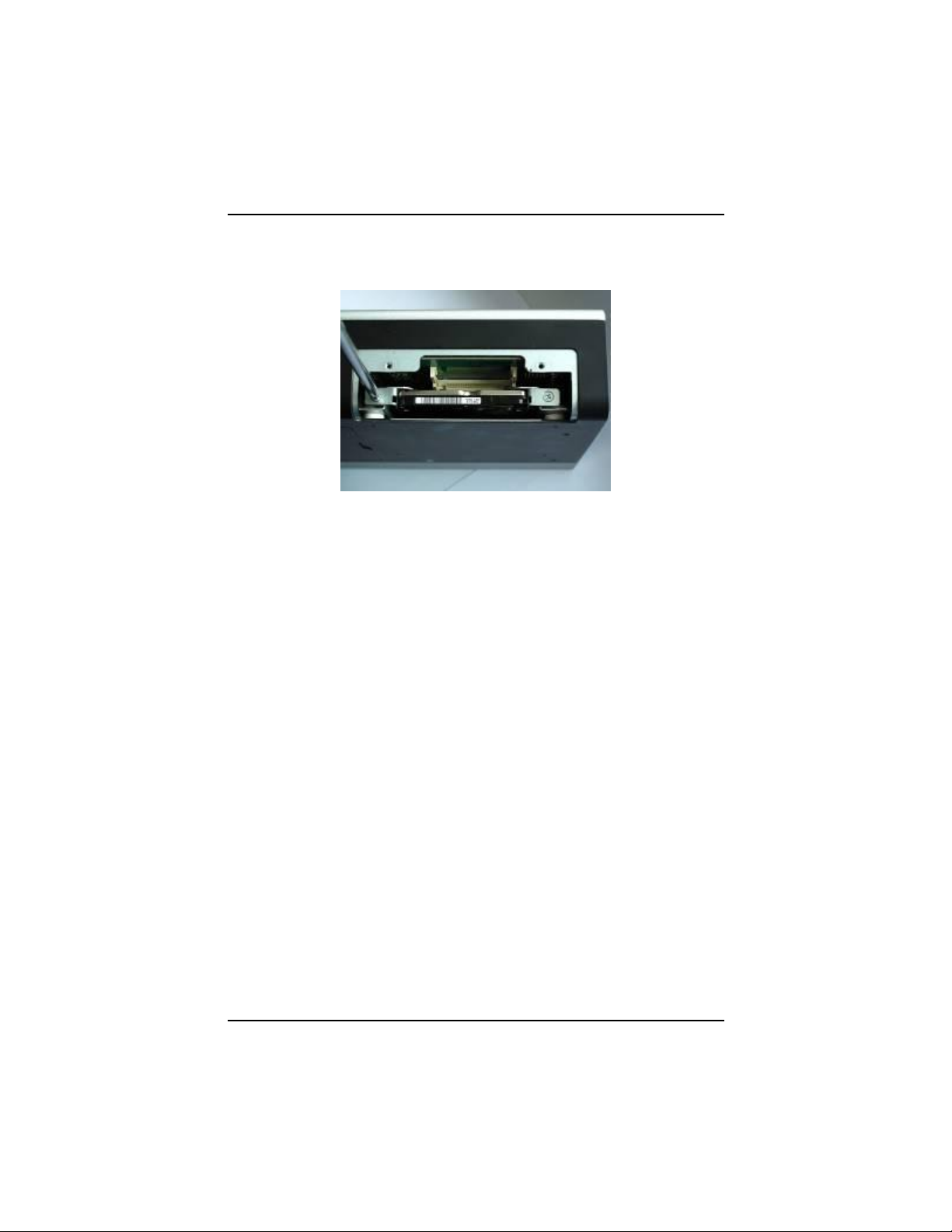
Step 5) Install the HDD bracket into the system carefully, and
fasten the screw of HDD bracket
Step 6) Close the HDD/CF Card cover of the chassis, and
fasten all screws.
Hardware Installation
Page 22
tBOX311-820-FL Series User’s Manual
14
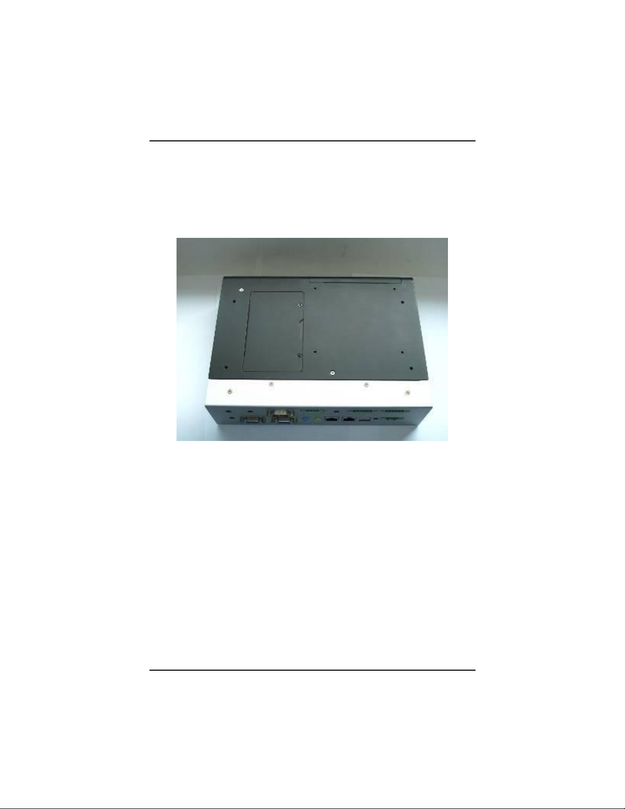
2.2 Installing the SIM Card and Express Mini
Card.
Step 1) Turn off the system, and unplug the power cord.
Step 2) Turn the system upside down to locate screws at the
bottom, loosen screws.
Hardware Installation
Page 23

tBOX311-820-FL Series User’s Manual
15
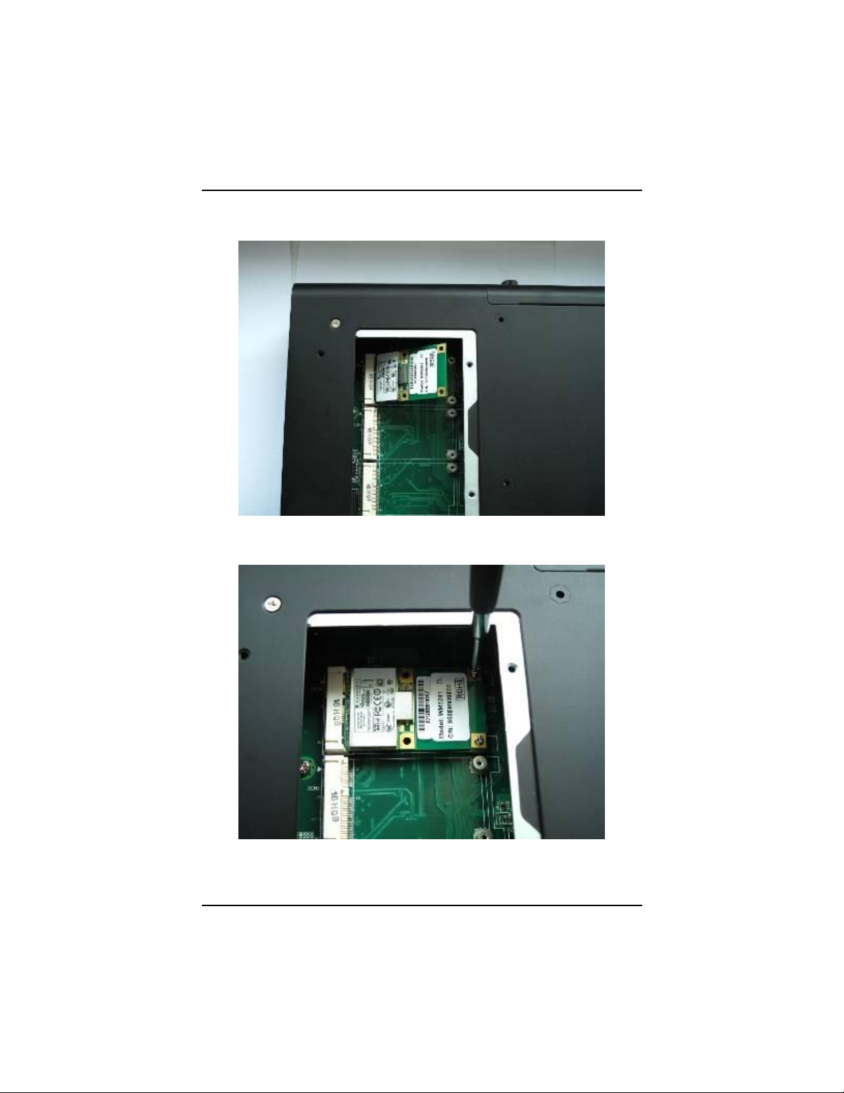
Step 3) Remove the bottom cover.
Step 4) Install SIM card into SIM card slot in right direction
Hardware Installation
Page 24
tBOX311-820-FL Series User’s Manual
16
Step 4) Slide Mini card into MiniCard slot cautiously.
Step 7) Fasten screw of Express Mini Card.
Hardware Installation
Page 25

tBOX311-820-FL Series User’s Manual
17
External Connectors
Section
VGA Connector
3.1
Serial Port Connector
3.2
Audio Phone Jack Connector
3.3
USB 2.0 Stack Port
3.4
LED Indicators
3.5
CANBUS connector
3.6
DC Power Input Connector
3.7
LAN connector
3.8
Digital I/O Connector
3.9
Internal Connectors
Section
SIM Card Connector
3.10
PCI-Express Mini Card Connector
3.11
CompactFlash Socket
3.12
SATA Connector
3.13
SATA Power Connector
3.14
CHAPTER 3
CONNECTORS
Proper jumper settings configure the tBOX311-820-FL to meet your
application purpose. We are herewith listing a summary table of all
jumpers and default settings for onboard devices, respectively.
Connectors connect the CPU card with other parts of the system. Loose
or improper connection might cause problems. Make sure all
connectors are properly and firmly connected. Here is a summary table
shows you all connectors on the tBOX311-820-FL Series.
Connectors
Page 26
tBOX311-820-FL Series User’s Manual
18
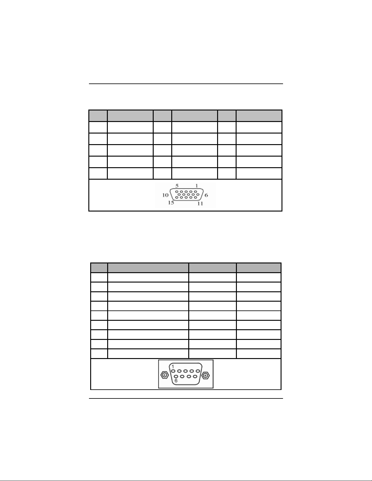
Pin
Signal
Pin
Signal
Pin
Signal
1
Red
2
Green
3
Blue
4
N.C.
5
GND
6
DETECT
7
GND
8
GND
9
VCC
10
GND
11
N.C.
12
DDC DATA
13
Horizontal Sync
14
Vertical Sync
15
DDC CLK
Pin
RS-232
RS-422
RS-485
1
DCD, Data carrier detect
TX-
Data-
2
RXD, Receive data
TX+
Data+
3
TXD, Transmit data
RX+
No Use
4
DTR, Data terminal ready
RX-
No Use
5
GND, ground
No use
No Use
6
DSR, Data set ready
No use
No Use
7
RTS, Request to send
No Use
No Use
8
CTS, Clear to send
No Use
No Use
9
RI, Ring indicator
No use
No Use
3.1 VGA Connector
CN19A is the upper connecoer with a DB15 connector commonly
used for the CRT Monitor.
3.2 Serial Port Connector
The COM Port connector is a standard DB-9 connector.The pin
assignment of RS-232/RS-422/RS-485 is listed on the following
table. If you need COM port to support RS-422 or RS-485,
please selection to the BIOS items.
Connectors
Page 27
tBOX311-820-FL Series User’s Manual
19
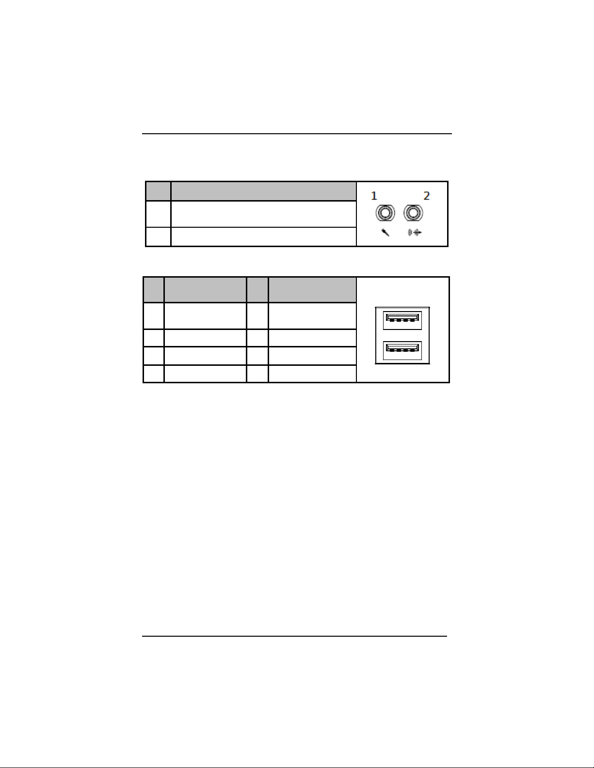
Pin
Signal
1
Microphone In
2
Line Out
Pin
Signal USB Port 0
Pin
Signal USB Port 6
USB
1 2 3 4
5 6 7 8
1
USB VCC
(+5V level)
5
USB VCC
(+5V level)
2
USB #0_D-
6
USB #6_D-
3
USB #0_D+
7
USB #6_D+
4
Ground (GND)
8
Ground (GND)
3.3 Audio Phone Jack Connector
These two audio jacks ideal are for Audio Mic-In and Audio
Line-out.
3.4 USB2.0 Stack Ports
Connectors
Page 28

tBOX311-820-FL Series User’s Manual
20
Status
WWAN
WLAN
P1~4
Bright
BIOS
process
done
Power
On
WWAN
be
activated
WLAN
be
activated
Programmi
ng by user.
flash
HDD
active
Pin
Signal
Isolated_GND
CAN_H
Chassis_GND
CN4
TB 3EHDRM 4P
1
2
3
4
CAN_L
1
Isolated GND
2
CAN Data L
3
Chassis GND
4
CAN Data H
3.5 LED Indicators
3.6 CANBUS connector
Connectors
Page 29

tBOX311-820-FL Series User’s Manual
21
Pin
Description
Definination
1
V+
For DC power in V+.
2
V-
For DC power in V-
3
ACC
For ACC (Ignition)
Pin
Description
LAN
1
MDI0+
2
MDI0-
3
MDI1+
4
MDI2+
5
MDI2-
6
MDI1-
7
MDI3+
8
MDI3-
A
Active LED
B
100/1000 LAN LED
3.7 DC Power Input connector
There are three pins of the DC-in connector as below table
3.8 LAN Connector (LAN1, LAN2)
The system is equipped with a RJ-45 connector for Gigabit LAN.
To connect the board to a 10/100/1000 Base-T hub, just plug
one end of the cable into LAN1 and LAN2, and connect the other
end to a 10/100/1000 Base-T hub.
Connectors
Page 30

tBOX311-820-FL Series User’s Manual
22
Pin
Signal (CN3)
Pin
Signal (CN2)
1
EXT. COM-
1
COM+
2
Data In 0
2
Data Out 0
3
Data In 1
3
Data Out 1
4
Data In 2
4
Data Out 2
5
Data In 3
5
Data Out 3
6
EXT. COM+
6
COM-
EXT_PWR
CN3
TB-ECH350RM 6Pin
1
2
3
4
5
6
EXT_COM
XIN00
XIN03
XIN02
XIN01
XOUTCOM-
XOUT00
XOUT01
XOUT02
CN2
TB-ECH350RM 6Pin
1
2
3
4
5
6
XOUT03
XOUTCOM+
3.9 Digital I/O Connector
The tBOX311-820-FL support an isolated 4-in/4-out Digital I/O
(DIO)
NOTE: Please refer to Appendix B for more information about
Digital I/O
Connectors
Page 31

tBOX311-820-FL Series User’s Manual
23
Pin
Signal
LOCK
OPEN
C1
C2
C3
C5
C6
C7
C1
SIM_PWR
C2
SIM_RESET
C3
SIM_CLK
C5
GND
C6
SIM_VPP
C7
SIM_DATA
Pin
Signal
Pin
Signal
1
WAKE#
2
+3.3VSB
3
No use
4
GND
5
No use
6
+1.5V
7
CLKREQ#
8
No use
9
GND
10
No use
11
REFCLK-
12
No use
13
REFCLK+
14
No use
15
GND
16
No use
17
No use
18
GND
19
No use
20
+3.3VSB
21
GND
22
PERST#
23
PE_RXN4
24
+3.3VSB
25
PE_RXP4
26
GND
27
GND
28
+1.5V
29
GND
30
SMB_CLK
31
PE_TXN4
32
SMB_DATA
33
PE_TXP4
34
GND
3.10 SIM Card Connector
The SIM Card slot (SCN3) is a ISO 7816 standard 6-pin
connector for PCI Express Mini Card (SCN4) used.
3.11 PCI-Express Mini Card Connector(SCN4,5,6)
Connectors
Page 32

tBOX311-820-FL Series User’s Manual
24
Pin
Signal
Pin
Signal
35
GND
36
USB_D3-
37
GND
38
USB_D3+
39
+3.3VSB
40
GND
41
+3.3VSB
42
LED_WWAN#
43
GND
44
LED_WLAN#
45
No use
46
LED_WPAN#
47
No use
48
+1.5V
49
No use
50
GND
51
No use
52
+3.3VSB
NOTE SCN6 only support USB2.0
Connectors
Page 33

tBOX311-820-FL Series User’s Manual
25
Pin
Signal
Pin
Signal
1
GND
26
CD1-
2
Data 3
27
Data 11
3
Data 4
28
Data 12
4
Data 5
29
Data 13
5
Data 6
30
Data 14
6
Data 7
31
Data 15
7
CS0#
32
CS1#
8
Address 10
33
VS1#
9
ATASEL
34
IORD#
10
Address 9
35
IOWR#
11
Address 8
36
WE#
12
Address 7
37
INTR
13
VCC
38
VCC
14
Address 6
39
CSEL#
15
Address 5
40
VS2#
16
Address 4
41
RESET#
17
Address 3
42
IORDY#
18
Address 2
43
DMAREQ
19
Address 1
44
DMAACK-
3.12 CompactFlash™ Socket
The tBOX311-820-FL is equipped with a CompactFlashTM disk
type-II socket on the solder side to support an IDE interface
CompactFlashTM disk card with DMA mode supported. The
socket is especially designed to avoid incorrect installation of the
CompactFlashTM disk card. When installing or removing the
CompactFlashTM disk card, please make sure the system power
is off.
Pin13 and Pin 38 power voltage can be referred to JP1 Jumper
Setting (See Section 3.2.1).
Connectors
Page 34

tBOX311-820-FL Series User’s Manual
26
Pin
Signal
Pin
Signal
20
Address 0
45
DASP#
21
Data 0
46
PDIAG#
22
Data 1
47
Data 8
23
Data 2
48
Data 9
24
IOCS16#
49
Data 10
25
CD2#
50
GND
1 2 3 4 5 6 7 8 9 10 11 12 13 14 15 16 17 18 19 20 21 22 23 24
26 27 28 29 30 31 32 33 34 35 36 37 38 39 40 41 42 43 44 45 46 47 48 49
25
50
Connectors
Page 35

tBOX311-820-FL Series User’s Manual
27
Pin
Signal
1
GND
2
SATA_TX+
3
SATA_TX-
4
GND
5
SATA_RX-
6
SATA_RX+
7
GND
Pin
Signal
1
N/A
2
N/A 3 N/A
4
COM
5
COM
6
COM
7
+5 VDC
8
+5 VDC
9
+5 VDC
10
COM
11
COM
12
COM
13
+12 VDC
14
+12 VDC
15
+12 VDC
1
15
3.13 SATA Connector
The SATA connectors are for high-speed SATA interface ports
and they can be connected to hard disk devices.
3.14 SATA Power Connector
Connectors
Page 36

tBOX311-820-FL Series User’s Manual
28
MEMO:
Connectors
Page 37

29
CHAPTER 4
Up arrow
Move to the previous item
Down arrow
Move to the next item
Left arrow
Move to the left side
Right arrow
Move to the right side
Esc key
Main Menu -- Quit and delete changes into CMOS
Status Page Setup Menu and Option Page Setup
Menu -- Exit current page and return to Main
Menu
PgUp/“+”ke y
Increase the numeric value or make changes
PgDn/“−“ k ey
Decrease the numeric value or make changes
F6 key
Load the default CMOS value from BIOS default
table, only for Option Page Setup Menu
F7 key
Load the Setup default, only for Option Page
Setup Menu
F10 key
Save all the CMOS changes, only for Main Menu
PHOENIX-AWARD BIOS UTILITY
The Phoenix-Award BIOS provides users with a built-in Setup
program to modify basic system configuration. All configured
parameters are stored in a flash-backed-up to save the Setup
information whenever the power is turned off.
4.1 Entering Setup
There is one way to enter the Setup program. You may either turn
ON the computer and press <Del> immediately.
4.2 Control Keys
Phoenix-Award BIOS Utility
Page 38

tBOX311-820-FL Series User’s Manual
30
4.3 Getting Help
Main Menu The online description of the highlighted setup function is
displayed at the bottom of the screen.
Status Page Setup Menu/Option Page Setup Menu Press <F1> to pop
out a General Help Window that provides the description of using
appropriate keys and possible selections for highlighted items.
Press <Esc> to exit the Help Window.
Phoenix-Award BIOS Utility
Page 39

tBOX311-820-FL Series User’s Manual
31
4.4 The Main Menu
Once you enter the Award BIOS CMOS Setup Utility, the Main Menu
appears on the screen. In the Main Menu, there are several Setup
functions and a couple of Exit options for your selection. Use arrow
keys to select the Setup Page you intend to configure then press
<Enter> to accept or enter its sub-menu.
NOTE If your computer can not boot after making and saving
system changes with Setup, the Award BIOS will reset
your system to the CMOS default settings via its built-in
override feature.
NOTE It is strongly recommended that you should avoid
changing the chipset’s defaults. Both Award and your
system manufacturer have carefully set up these defaults
that provide the best performance and reliability.
Phoenix-Award BIOS Utility
Page 40

tBOX311-820-FL Series User’s Manual
32
4.5 Standard CMOS Setup Menu
The Standard CMOS Setup Menu displays basic information about
your system. Use arrow keys to highlight each item, and use <PgUp>
or <PgDn> key to select the value you want in each item.
Date
The date format is <day> <month> <date> <year>.
Time
This item shows current time of your system with the format
<hour> <minute> <second>. The time is calculated based on
the 24-hour military-time clock. For example, 1 p.m. is
13:00:00.
NOTE If system is power failure, the date and time will come back
to previous setup.
Phoenix-Award BIOS Utility
Page 41

tBOX311-820-FL Series User’s Manual
33
No errors
The system booting will halt on any errors detected.
(default)
All errors
Whenever BIOS detects a non-fatal error, the
system will stop and you will be prompted.
All, But
The system booting will not stop for a keyboard
Keyboard
error; it will stop for other errors.
IDE Primary Master/Primary Slave
These items identify the types of each IDE channel installed in
the computer, so, IDE type is auto detection.
Video
Select the display adapter type for your system.
Halt On
This item determines whether the system will halt or not, if an error is
detected while powering up.
Press <Esc> to return to the Main Menu page. USB Device Setting
Phoenix-Award BIOS Utility
Page 42

tBOX311-820-FL Series User’s Manual
34
4.6 Advanced BIOS Features
This section allows you to configure and improve your system, to set
up some system features according to your preference.
Phoenix-Award BIOS Utility
Page 43

tBOX311-820-FL Series User’s Manual
35
CPU Features
Scroll to this item and press <Enter> to view the CPU Feature sub
menu.
Phoenix-Award BIOS Utility
Page 44

tBOX311-820-FL Series User’s Manual
36
Harddisk boot priority
Scroll to this item and press <Enter> to view the sub menu to decide
the disk boot priority
Phoenix-Award BIOS Utility
Page 45

tBOX311-820-FL Series User’s Manual
37
System System requires correct password before booting, and
also before permitting access to the Setup page.
Setup System will boot, but requires correct password before
permitting access to Setup. (Default value)
Phoenix-Award BIOS Utility
Page 46

tBOX311-820-FL Series User’s Manual
38
NOTE To disable the security, select PASSWORD SETTING at
Main Menu and then you will be asked to enter a
password. Do not type anything, just press <Enter>
and it will disable the security. Once the security is
disabled, the system will boot and you can enter Setup
freely.
Phoenix-Award BIOS Utility
Page 47

tBOX311-820-FL Series User’s Manual
39
APIC Mode
APIC (Advanced Programmable Interrupt Controller) mode is enabled
that provides symmetric multiprocessing (SMP) for systems.
NOTE APIC Mode has been locked and cannot be modified.
Phoenix-Award BIOS Utility
Page 48

tBOX311-820-FL Series User’s Manual
40
MPS Version Control For OS
This item specifies the version of the Multiprocessor Specification
(MPS). Version 1.4 has extended configuration tables to improve
support for multiple PCI bus configurations and provide future
expandability.
Press <Esc> to return to the Main Menu page.
Phoenix-Award BIOS Utility
Page 49

tBOX311-820-FL Series User’s Manual
41
4.7 Advanced Chipset Features
This section contains completely optimized chipset’s features on the
board that you are strongly recommended to leave all items on this
page at their default values unless you are very familiar with the
technical specifications of your system hardware.
Phoenix-Award BIOS Utility
Page 50

tBOX311-820-FL Series User’s Manual
42
DRAM Timing Selectable
Use this item to increase the timing of the memory. This is related to
the cooling of memory.
System BIOS Cacheable
Selecting Enabled allows caching of the system BIOS ROM at
F0000h-FFFFFh, resulting in better system performance. However, if
any program writes to this memory area, a system error may result.
The default value is “Disabled”.
Video BIOS Cacheable
This item allows you to change the Video BIOS location from ROM to
RAM. Video Shadow will increase the video speed.
*** VGA Setting ***
On-Chip Frame Buffer
Size
Use this item to set the VGA frame buffer size.
Phoenix-Award BIOS Utility
Page 51

tBOX311-820-FL Series User’s Manual
43
Boot Type (CRT Only)
This item is to select Display Device that the screen will be shown. But
its default is CRT Only and cannot be modified.
Panel Scaling (AUTO by default)
This item shows the setting of panel scaling and operates the scaling
function that the panel output can fit the screen resolution connected
to the output port. Its default is AUTO and cannot be modified.
Press <Esc> to return to the Main Menu page.
Phoenix-Award BIOS Utility
Page 52

tBOX311-820-FL Series User’s Manual
44
4.8 Integrated Peripherals
This section allows you to configure your OnChip IDE Device,
Onboard Device, SuperIO Device and USB Device Setting.
Phoenix-Award BIOS Utility
Page 53

tBOX311-820-FL Series User’s Manual
45
OnChip IDE Device
Scroll to this item and press <Enter> to view the sub menu OnChip
IDE Device.
IDE HDD Block Mode
Block mode is also called block transfer, multiple commands,
ormultiple sectors read/write. If your IDE hard drive supports
block mode (most new drives do), select Enabled for
automatic detection of the optimal number of block read/writes per
sector the drive can support.
Press <Esc> to return to the Integrated Peripherals page.
Phoenix-Award BIOS Utility
Page 54

tBOX311-820-FL Series User’s Manual
46
Phoenix-Award BIOS Utility
Page 55

tBOX311-820-FL Series User’s Manual
47
Onboard Device
Scroll to this item and press <Enter> to view the sub menu Onboard
Device.
Intel HD Audio Controller
Choose Auto to Disabled an Intel HD Audio controller.
SDIO/MC Controller (Enabled)
Choose Enabled on the SDIO/MMC Controller
Phoenix-Award BIOS Utility
Page 56

tBOX311-820-FL Series User’s Manual
48
Press <Esc> to return to the Integrated Peripherals page.
Phoenix-Award BIOS Utility
Page 57

49
Super IO Device
Onboard Serial Port 1/2
Select an address and corresponding interrupt for the serial
port. There are several options for your selection.
tBOX311-820-FL Series User’s Manual
Press <ESC> to return to the Integrated Peripherals page.
Phoenix-Award BIOS Utility
Page 58

tBOX311-820-FL Series User’s Manual
50
Phoenix-Award BIOS Utility
Page 59

tBOX311-820-FL Series User’s Manual
51
Phoenix-Award BIOS Utility
Page 60

tBOX311-820-FL Series User’s Manual
52
USB Device Setting
Scroll to this item and press <Enter> to view the sub menu USB
Device Setting.
Press <Esc> to return to the Integrated Peripherals page.
Onboard Lan Boot ROM
Use this item to enable or disable the Boot ROM function of the
onboard LAN chip when the system boots up. Its default is disable.
Phoenix-Award BIOS Utility
Page 61

tBOX311-820-FL Series User’s Manual
53
4.9 Power Management Setup
The Power Management Setup allows you to save energy of your
system effectively. It will shut down the hard disk and turn OFF video
display after a period of inactivity.
ACPI Function
Advanced Configuration and Power Management (ACPI).
The function is always “Enabled”.
Phoenix-Award BIOS Utility
Page 62

tBOX311-820-FL Series User’s Manual
54
4.10 PnP/PCI Configuration Setup
This section describes the configuration of PCI (Personal Computer
Interconnect) bus system, which allows I/O devices to operate at
speeds close to the CPU speed while communicating with other
important components. This section covers very technical items that
only experienced users could change default settings.
Reset Configuration Data
Normally, you leave this item Disabled. Select Enabled to reset
Extended System Configuration Data (ESCD) when you exit Setup or
if installing a new add-on cause the system reconfiguration a serious
conflict that the operating system can not boot. Options: Enabled,
Disabled.
Phoenix-Award BIOS Utility
Page 63

tBOX311-820-FL Series User’s Manual
55
Resources Controlled By
The Award Plug and Play BIOS can automatically configure all boot
and Plug and Play-compatible devices. If you select Auto, all interrupt
request (IRQ), DMA assignment and Used DMA fields disappear as
the BIOS automatically assign them. The default value is “Auto”. The
other option is “Manual”
Phoenix-Award BIOS Utility
Page 64

tBOX311-820-FL Series User’s Manual
56
Phoenix-Award BIOS Utility
Page 65

tBOX311-820-FL Series User’s Manual
57
IRQ Resources
When resources are controlled manually, assign each system interrupt
to one of the following types in accordance with the type of devices
using the interrupt:
1. Legacy ISA Devices compliant with the original PC AT bus
specification, requiring a specific interrupt (such as IRQ4 for serial
port 1).
2 . PCI/ISA PnP Devices compliant with the Plug and Play standard,
whether designed for PCI or ISA bus architecture.The default value
is “PCI/ISA PnP”.
PCI/VGA Palette Snoop
Some non-standard VGA display cards may not show colors
properly. This item allows you to set whether MPEG
ISA/VESA VGA Cards can work with PCI/VGA or not. When
enabled, a PCI/VGA can work with a MPEG ISA/VESA VGA
card; when disabled, a PCI/VGA cannot work with a MPEG
ISA/VESA Card.
** PCI Express relative items **
Phoenix-Award BIOS Utility
Page 66

tBOX311-820-FL Series User’s Manual
58
Maximum Payload Size
When using DDR SDRAM and Buffer size selection,
another consideration in designing a payload memory is
the size of the buffer for data storage. Maximum Payload
Size defines the maximum TLP (Transaction Layer Packet)
data payload size for the device.
Press <Esc> to return to the Main Menu page.
Phoenix-Award BIOS Utility
Page 67

tBOX311-820-FL Series User’s Manual
59
Phoenix-Award BIOS Utility
Page 68

tBOX311-820-FL Series User’s Manual
60
4.11 PC Health Status
This section supports hardware monitoring that lets you monitor those
parameters for critical voltages, temperatures and fan speed of the
board.
Press <Esc> to return to the Main Menu page.
Phoenix-Award BIOS Utility
Page 69

tBOX311-820-FL Series User’s Manual
61
4.12 Load Optimized Defaults
This option allows you to load your system configuration with default
values. These default settings are optimized to enable high
performance features.
To load CMOS SRAM with SETUP default values, please enter “Y”. If
not, please enter “N”.
Phoenix-Award BIOS Utility
Page 70

tBOX311-820-FL Series User’s Manual
62
4.13 Set Supervisor/User Password
You can set a supervisor or user password, or both of them.
The differences between them are:
1 Supervisor password: You can enter and change the
options on the setup menu.
2 User password: You can just enter, but have no right to
change the options on the setup menu.
When you select this function, the following message will appear at
the center of the screen to assist you in creating a password.
ENTER PASSWORD
Type a maximum eight-character password, and press <Enter>. This
typed password will clear previously entered password from the
CMOS memory. You will be asked to confirm this password. Type this
password again and press <Enter>. You may also press <Esc> to
abort this selection and not enter a password.
To disable the password, just press <Enter> when you are prompted
to enter a password. A message will confirm the password is getting
disabled. Once the password is disabled, the system will boot and you
can enter Setup freely.
PASSWORD DISABLED
When a password is enabled, you have to type it every time you
enter the Setup. It prevents any unauthorized persons from changing
your system configuration.
Additionally, when a password is enabled, you can also require the
BIOS to request a password every time the system reboots. This
would prevent unauthorized use of your computer.
You decide when the password is required for the BIOS Features
Setup Menu and its Security option. If the Security option is set to
“System”, the password is required during booting up and entry into
the Setup; if it is set as “Setup”, a prompt will only appear before
entering the Setup.
Phoenix-Award BIOS Utility
Page 71

tBOX311-820-FL Series User’s Manual
63
Phoenix-Award BIOS Utility
Page 72

tBOX311-820-FL Series User’s Manual
64
4.14 Save & Exit Setup
This section allows you to determine whether or not to accept your
modifications. Type “Y” to quit the setup utility and save all changes
into the CMOS memory. Type “N” to bring you back to the Previous
Setup utility.
Phoenix-Award BIOS Utility
Page 73

tBOX311-820-FL Series User’s Manual
65
4.15 Exit Without Saving
Select this option to exit the Setup utility without saving changes you
have made in this session. Type “Y”, and it will quit the Setup utility
without saving your modifications and come back to Previous Setup
utility. Type “N” to return to the Setup utility.
Phoenix-Award BIOS Utility
Page 74

tBOX311-820-FL Series User’s Manual
66
MEMO:
Phoenix-Award BIOS Utility
Page 75

tBOX311-820-FL Series User’s Manual
67
APPENDIX A
WATCHDOG TIMER
About Watchdog Timer
Software stability is major issue in most applications. Some embedded
systems are not watched by human for 24 hours. It is usually too slow
to wait for someone to reboot when computer hangs. The systems
need to be able to reset automatically when things go wrong. The
watchdog timer gives us solution.
The watchdog timer is a counter that triggers a system reset when it
counts down to zero from a preset value. It can be set by programming
its value. The software starts counter with an initial value and must
reset it periodically. If the counter ever reaches zero which means the
software has crashed, the system will reboot.
How to Use the Watchdog Timer
Assembler Sample Code
;Enable WDT:
mov dx,2Eh
mov al,87h ;Un-lock super I/O
out dx,al
out dx,al
;Select Logic device:
mov dx,2Eh
mov al,07h
out dx,al
mov dx,2Fh
mov al,08h
out dx,al
Watchdog Timer
Page 76

tBOX311-820-FL Series User’s Manual
68
;Select WDT Function:
mov dx,2Eh
mov al,2Dh
out dx,al
mov dx,2Fh
mov al,20h
out dx,al
;Activate WDT:
mov dx,2Eh
mov al,30h
out dx,al
mov dx,2Fh
mov al,01h
out dx,al
;Set Second or Minute :
mov dx,2Eh
mov al,F5h
out dx,al
mov dx,2Fh
mov al,Nh ;N=00h or 08h(See below
Note)
out dx,al
;Set base timer :
mov dx,2Eh
mov al,F6h
out dx,al
mov dx,2Fh
mov al, Mh ;M=00h,01h,02h,.....FFh
(Hex),Value=0 to 255
out dx, al ; (See below Note)
Watchdog Timer
Page 77

tBOX311-820-FL Series User’s Manual
69
;Disable WDT:
mov dx,2Eh
mov al,30h
out dx,al
mov dx,2Fh
mov al, 00h ;Can be disable at ant time
out dx,al
Note:
When N’s value is 00h, the time base is set second.
M = 00: Time-out Disable
01: Time-out occurs after 1 second
02: Time-out occurs after 2 seconds
03: Time-out occurs after 3 seconds
FF: Time-out occurs after 255 seconds
Sample of Watchdog application
Assume there is program A which needs to maintain running in a
system. The value of Watchdog Timer must be set bigger than
the running time of program A. Then, after the running time of
program A is finished, either to disable or to reset watchdog
timer.
When program A has problems to make system shut down, the
system can be rebooted by Watchdog timer when the value of
watchdog timer is countdowned to 0.
The below flowchart can be referred to edit program A
Watchdog Timer
Page 78

tBOX311-820-FL Series User’s Manual
70
Watchdog Timer
Page 79

tBOX311-820-FL Series User’s Manual
71
APPENDIX B
DIGITAL I/O
Digital I/O Software Programming
I2C to GPIO PCA9535PW GPIO Group0[3:0] is input,
Group0[7:4] is output.
I2C address: 0b0100000x.
Registers:
Register 0: Input Group0 register.
Register 2: Output Group0 register.
Digital I/O
Page 80

tBOX311-820-FL Series User’s Manual
72
MEMO:
Digital I/O
Page 81

tBOX311-820-FL Series User’s Manual
73
D/W Switch in “D”
Dry Contact Support
D/W
Switch
Ext. PWR
6
1
Ext. COM
Int. PWR
2
5V
tBox311 Internal
Digital Input
CN3
APPENDIX C
DIGITAL I/O Wiring
Digital I/O Specification
Digital I/O Port support 4bits input and 4bits output.
Digital Input(CN3):
Voltage rating: 0 ~ 30Vdc.
Vil: +/-5Vdc max.(COM to DI).
Vih: +/-5Vdc min.(COM to DI).
Digital Output(CN2):
Max. output sink current: 200mA per channel
COM+/- Voltage: 12Vdc ~ 24Vdc
All output port is open collector.
DI Connection Example:
Digital I/O Wiring
Page 82

tBOX311-820-FL Series User’s Manual
74
Power
+
-
Ext. Power +
Ext. Power -
D/W
Switch
6
1
Int. PWR
2
5V
D/W Switch in “D”
Wet Contact
Sink mode Support
Switch NPN
Ext. Power -
tBox311 Internal
Digital Input
CN3
Power
+
-
Ext. Power +
Ext. Power -
D/W
Switch
6
Digital Input
CN3
1
Int. PWR
2
5V
D/W Switch in “W”
Wet Contact
Source mode Support
Switch
PNP
Ext. Power +
tBox311 Internal
Digital I/O Wiring
Page 83

75
DO Connection Example:
Ext. Power +
6
Digital Output
CN2
1
2
5V
tBox311 Internal
Ext. Power -
Relay
LED
tBOX311-820-FL Series User’s Manual
Digital I/O Wiring
Page 84

tBOX311-820-FL Series User’s Manual
76
MEMO:
Digital I/O Wiring
Page 85

tBOX311-820-FL Series User’s Manual
77
APPENDIX D
Power On Procedure
tBOX311-820-FL is an embedded system which is designed for vehicle,
and supports both vehicle with +12V car battery or +24V car battery.
The boot up requirement is quite different from normal embedded
system. Please do follow the instruction in this section.
1 Introduction
Most of the times, car batteries will stay at 13.5V~15V (for 12V Mode),
or at 27V~30V (for 24V Mode) while car engine is running, so specified
above 13V or 26V power on will ensure that car engine is running and
prevents a cold crank while car engine is started.
This cold crank will cause car battery voltage to drop to minimum 6V (at
12V mode) or more low, at this time,the most difficult task to provide a
stable +12V output power to PC system to prevent PC system from cold
boot.
In order to ensure the vehicle could provide a stable DC power,
tBOX311-820-FL will detect the DC power from source is higher than
the Start Voltage or not.
Power On Procedure
Page 86

tBOX311-820-FL Series User’s Manual
78
Mode
Operating
Voltage
Start
Voltage
*
Low Voltage
**
Very Low
Voltage
***
12V
9V~16V
11.5V
10.5V
9V
24V
18V~32V
23V
21V
18V
2 Power Input Mode Setting
To support different vehicle and battery protection, it has two types of
power Input mode:
*Start Voltage: The intelligent power board will start up and initial
whole system when DC power source higher than this setting.
**Low Voltage: When DC power source lower than this setting,
intelligent vehicle powerboard will run Low voltage Counter.
When counter time out, tBOX311-820-FL will shutdown system
automatically, and intelligent vehicle power board will stay in
standby mode(max. power consumption is under 5mA)
**Very Low Voltage: When DC power source lower than this
setting, intelligent vehicle powerboard will run Very Low voltage
Counter. When counter time out, intelligent vehicle powerboard
will turn off power immeditly without shutdown procedure.
Power On Procedure
Page 87

tBOX311-820-FL Series User’s Manual
79
Pin
Description
Definination
1
V+
For DC power in V+.
2
V-
For DC power in V-
3
ACC
For ACC (Ignition)
3 DC-inlet Introduction
There are three pins of the DC-in connector as below table:
ACC means “accessories” . Mainly, it acts both notice signal to
all electronical devices, and also provides DC from battery.
When user puts car key into ignition, and turn the key to this
position, user can run radio, CD player, air condition or other
electronical accessories in vehicle. Below picture is a normal car
ignition with ACC position:
Power On Procedure
Page 88

tBOX311-820-FL Series User’s Manual
80
4 Power on cabling example
Due to the voltage of ACC is usually the same as V+, user could
connect V+ with ACC to initial the tBOX311-820-FL.
1. Power On without ACC control: ACC connect to V+.
2. Power On with ACC control: ACC connector to ignition
switch.
Power On Procedure
 Loading...