

Page 1
PANEL5155-807
Open Frame 15” TFT Touch
Panel Computer
User’s Manual
Page 2

ii
Disclaimers
The information in this manual has been carefully checked and is believed to
be accurate. AXIOMTEK Co., Ltd. assumes no responsibility for any
infringements of patents or other rights of third parties, which may result from
its use.
AXIOMTEK assumes no responsibility for any inaccuracies that may be
contained in this document. AXIOMTEK makes no commitment to update or
to keep current the information contained in this manual.
AXIOMTEK reserves the right to make improvements to this document and/or
product at any time and without notice.
No part of this document may be reproduced, stored in a retrieval system, or
transmitted, in any form or by any means, electronic, mechanical,
photocopying, recording, or otherwise, without the prior written permission of
AXIOMTEK Co., Ltd.
©Copyright 2007 by AXIOMTEK Co., Ltd.
All rights reserved.
March 2007, Version A4
Printed in Taiwan
Page 3

iii
Safety Approvals
CE Marking
FCC Class A
FCC Compliance
This equipment has been tested and complies with the limits for a
Class A digital device, pursuant to Part 15 of the FCC Rules. These
limits are designed to provide reasonable protection against harmful
interference in a residential installation. If not installed and used in
accordance with proper instructions, this equipment might genera te or
radiate radio frequency energy and cause harmful interference to
radio communications. However, there is no guarantee that
interference will not occur in a particular installation. If this equipment
does cause harmful interference to radio or television reception, which
can be determined by turning the equipment off and on, the user is
encouraged to try to correct the interference by one or more of the
following measurers:
1. Reorient or relocate the receiving antenna.
2. Increase the separation between the equipment and receiver.
3. Connect the equipment into an outlet on a circuit different from
that to which the receiver is connected.
4. Consult the dealer or an experienced radio/TV technician for help.
Shielded interface cables must be used in order to comply with
emission limits.ou
Page 4

iv
Safety Precautions
Before getting started, read the follo wing important cau tions.
1. The PANEL5155-807 does not come equipped with an
operating system. An operating system must be loaded first
before installing any software into the computer.
2. Be sure to ground yourself to prevent static charge when
installing the internal components. Use a grounding wrist strap
and place all electronic components in any static-shielded
devices. Most electronic components are sensitive to static
electrical charge.
3. Disconnect the power cord from the PANEL5155-807 before
making any installation. Be sure both the system and the
external devices are turned OFF. Sudden surge of power
could ruin sensitive components. Make sure the
PANEL5155-807 is properly grounded.
4. The brightness of the flat panel display decreases with usage.
However, hours of use vary depending on the application
environment.
5. Turn OFF the system power before cleaning. Clean the
system using a cloth only. Do not spray any liquid cleaner
directly onto the screen. The PANEL5155-807 may come with
or w/o a touch screen. Although the touch screen is chemical
resistant, it is recommended that you spray th e liquid cleaner
on a cloth first before wiping the screen. In case yo ur system
comes without the touch screen, you must follow the same
procedure and not spray any cleaner on the flat panel direc tly .
6. Avoid using sharp objects to operate the touch screen.
Scratches on the touch screen may cause malfunction or
internal failure to the touch screen.
7. The flat panel display is not susceptibl e to shock or vibration.
When assembling the PANEL5155-807, make sure it is
securely installed.
Page 5

v
5. Do not open the system’s back cover. If opening the cover for
maintenance is a must, only a trained technician is allowed to do
so. Integrated circuits on computer boards are sensitive to static
electricity. To avoid damaging chips from electrostatic discharge,
observe the following precautions:
9 Before handling a board or integrated circuit, touch an
unpainted portion of the system unit chassis for a few seconds.
This will help to discharge any static electricity on your body.
9 When handling boards and components, wear a
wrist-grounding strap, available from most electronic
component stores.
Trademarks Acknowledgments
AXIOMTEK is a trademark of AXIOMTEK Co., Ltd.
IBM, PC/AT, PS/2, VGA are trademarks of International
Business Machines Corporation.
Intel and Pentium are trademarks of Intel Corporation.
MS-DOS, Microsoft C and Quick BASIC are trademarks of
Microsoft Corporation.
VIA is a trademark of VIA Technologies, Inc.
SST is a trademark of Silicon Storage Technology, Inc.
UMC is a trademark of United Microelectronics Corp oration.
Other brand names and trademarks are th e properties of their
respective owners.
Page 6

vi
This page does not contain any information.
Page 7

Table of Contents
vii
Table of Contents
Disclaimers........................................................................ii
Safety Approvals................................................... .............iii
FCC Compliance ..............................................................iii
Safety Precautions .............................................................iv
C h a p t e r 1 .....................................................................1
Introduction..........................................................................1
1.1 General Description ............................................1
1.2 Specifications ......................................................1
1.2.1 Main CPU board ..................................................1
1.2.2 I/O System ...........................................................2
1.2.3 System Specification ..........................................3
1.3 Dimensions ..........................................................3
1.4 Rear View and I/O Outlets ..................................5
1.4.1 Rear View ............................................................5
1.4.2 I/O Outlet..................................................... .... ....6
1.5 Package list..........................................................7
C h a p t e r 2 .....................................................................8
Hardware Installation.........................................................8
2.1 CPU and DRAM Installation ...............................8
2.2 HDD Installation................ ........... ......................11
2.3 Serial Port Interface ..........................................12
2.4 VGA..................... ................................................12
2.5 Ethernet..............................................................12
2.6 Mountings: VESA/ Wall/ Panel mount.............13
2.6.1 VESA ARM ..........................................................13
2.6.2 Wall Mount.........................................................14
2.6.3 Panel-Mount Kit Assembly...............................15
C h a p t e r 3 ...................................................................16
Driver Installation.............................................................16
3.1 System................................................................16
Page 8

Table of Contents
viii
3.2 P5155-807S Touch Screen ...............................17
3.2.1 Specification .....................................................17
3.2.2 Driver Installation- Windows2000/XP..............18
3.3 P5155-807R Touch Screen ...............................21
3.3.1 Specification .....................................................21
3.3.2 Driver Installation- Windows2000/XP..............22
3.3.3 Driver Installation- DOS....................................24
C h a p t e r 4 ...................................................................28
Embedded O.S. Installation........................................ .....28
4.1 Windows XP Embedded ...................................28
4.1.1 Calibration Touch Screen for P5155-807S......29
4.1.2 Calibration Touch Screen for P5155-807R......29
4.2 Windows CE.NET 5.0 ..................................... ...30
4.2.1 Calibration Touch Screen for P5155-807S......30
4.2.2 Calibration Touch Screen for P5155-807R......30
A p p e n d i x A ..............................................................31
SBC86807 BIOS Setup.......................................................31
A.1 BIOS Introduction ..................................................31
A.2 BIOS Setup.............................................................31
A.2.1 Standard CMOS Setup .....................................33
A.2.2 Advanced BIOS Features.................................36
A.2.3 Advanced Chipset Features ...........................40
A.2.4 Integrated Peripherals .....................................42
A.2.5 Power Management Setup..............................45
A.2.6 PNP/PCI Configuration................ .... .... ........ ... ..48
A.2.7 PC Health Status................................................49
A.2.8 Frequency/Voltage Control............... .............50
A.2.9 Load Fail-Safe Defaults ....................................51
A.2.10 Load Optimized Defaults .................................52
A.2.11 Set Supervisor/User Password .........................53
A.2.12 Save & Exit Setup ..............................................54
A.2.13 Exit Without Saving ...........................................55
Appendix B.........................................................................56
Page 9

Table of Contents
ix
Power Supply Specification ............................................56
B.1 Power Supply: FSP180-50PLA1 (180W, AC
110~230V Input)...............................................................56
B.1.1 ELECTRICAL REQUIREMENTS ...................................56
B.1.2 EFFICIENCY ..............................................................59
B.1.3 ENVIRONMENTAL REQUIREMENTS..........................59
B.1.4 MTBF .........................................................................59
B.1.5 SAFETY ......................................................................59
B.2 Power Supply: FSP200-62DL (200W, DC 18~36V
Input)…………………………………………………………60
B.2.1 ELECTRICAL REQUIREMENTS ...................................60
B.2.2 EFFICIENCY ..............................................................63
B.2.3 ENVIRONMENTAL REQUIREMENTS..........................63
B.2.4 MTBF .........................................................................63
B.2.5 SAFETY ......................................................................63
Page 10

PANEL5155-807 User’s Manual
Introduction
1
C h a p t e r 1
Introduction
This chapter contains the general information and the detail
specifications of the PANEL5155-807. Chapter 1 includes the
following sections:
General Description
System Specification
Dimensions
Back View & I/O Outlets
Package List
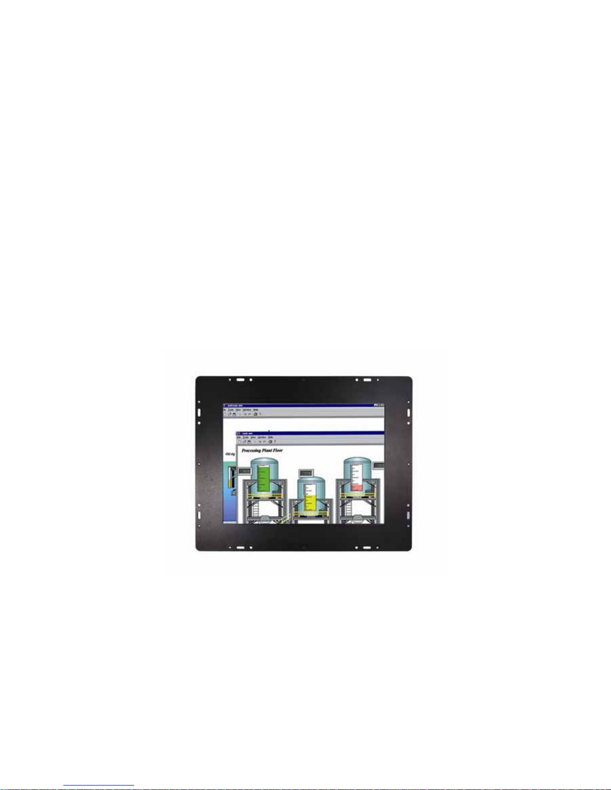
1.1 General Description
The PANEL5155-807 is an Open Frame TFT Touch Panel PC which
equipped with superior Pentium
®
M/Celeron® M processors and 15"
XGA LCD display. The paradigmatic industrial panel computer,
P5155-807, is a complete full-function and extreme cost-effective
industrial HMI controller.
This ideal industrial-grade panel computer PANEL5155-807 can be
applied to the several of industrial or commercial projects, such as
transportation, factory automation, HMI machine controller, Point Of
Sales, KIOSK and more. Moreover, PANEL5155-807 provides highly
reliable and highly flexible industrial-grade products in all-in-one
solutions.
1.2 Specifications
1.2.1 Main CPU board
CPU: Socket 479 for Intel® Pentium® M and Intel® Celeron®
M Processors.
System Chipset: Intel
®
852GM+ICH*4
BIOS: Phoenix-Award BIOS, Y2K compliant
4Mbit Flash, DMI, Plug and Play
SmartView for multiple LCD type selection, display
mode option and application extension features
Page 11

PANEL5155-807 User’s Manual
Introduction
2
RPL/PXE Ethernet Boot ROM
“Load Optimized Default” to backup customized
Setting in the BIOS flash chip to prevent from CMOS
battery fail
System Memory: One 184-pin DDR SDRAM DIMM
Maximum DDR of up to 1GB DDR266
L2 Cache: integrated in CPU
Bus Clock: 400 MHz
Watchdog Timer: Up to 255 levels as Reset feature
1.2.2 I/O System
Standard I/O:
− 3 x serial ports with power; 3 x RS-232
− 1 x PS/2 for Keyboard Interface
− 1 x PS/2 for Mouse Interface
− 4 x USB Ports 2.0 compliant
−
1 x 15 pin(female) for VGA output
Ethernet:
One Realtek 8100C PCI Bus 10/100M Base-T
One Realtek 8110SC with Giga LAN
Wake On LAN (via ATX power supply)
Equipped with RJ-45 interface
Optional with Realtek RTL8110S for 10/100/10 00 Base-T
Audio:
Realtek AC’97 codec audio
MIC-in, Line-out
Onboard IDE:
2 parallel ATA-100 as 1 * 44-pin 2.0 pitch box-header and
1 * 40-pin 2.0 pitch box-heade r.
PATA-100 as PIO Mode 0-4, DMA Mode 0-2 and Ultra
DMA/33/66/100.
Compact Flash Socket:
One Compact Flash Type II Socket ( Optional)
Page 12

PANEL5155-807 User’s Manual
Introduction
3
1.2.3 System Specification
15” TFT LCD
Disk drive housing:
− 1 x internal 3.5” drive
AC power supply
Heat dispensing design
Net weight:
− 8.8 Kgs
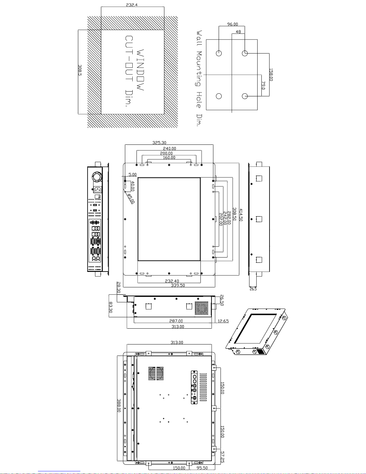
Dimension (main body size):
− 414.5 x 325.3 x 78.9mm
Operating temperature:
− O° to 45°C ; Relative umidity:50%
Relative humidity:
− 10% to 85% @ 40° C, non-condensing
Altitude:
− 10,000 ft. (3,000 meters)
Vibration (operating):
− 5 to 500 Hz, 1 G random
Shock (operating):
− 10 G peak acceleration (11 msec. duration)
1.3 Dimensions
The following diagrams show the dimensions and outlines of
P ANEL5155-807.
Page 13
Page 14
PANEL5155-807 User’s Manual
Introduction
5
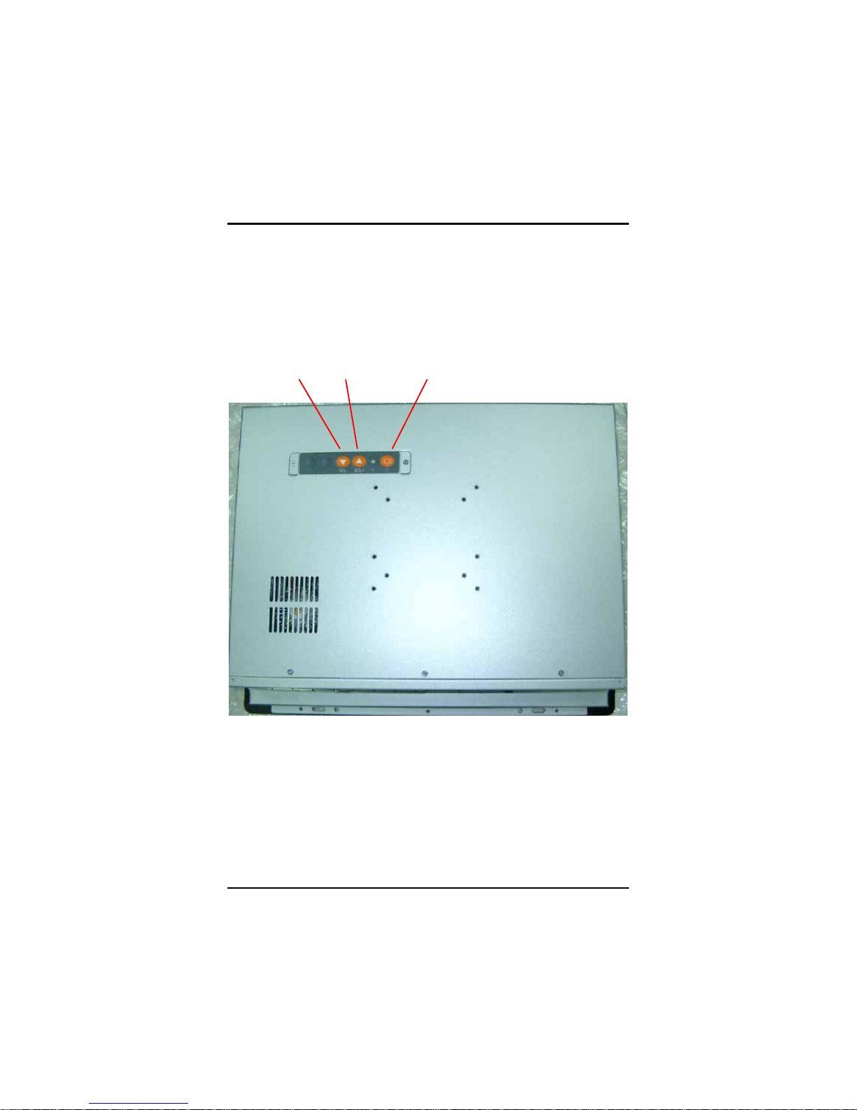
1.4 Rear Vie w and I/O Outlets
1.4.1 Rear View
The figure below shows the features and controls on the
PANEL5155-807 Rear chassis.
SEL- SEL+ Backlight ON/OFF
Page 15
PANEL5155-807 User’s Manual
Introduction
6
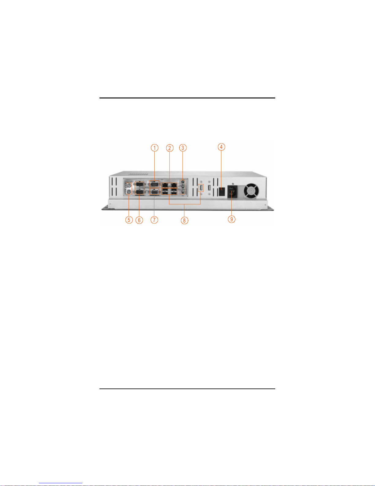
1.4.2 I/O Outlet
The following figure shows the I/O locations of the PANEL5155-807.
1:
COM 3
6:
COM 1 & 2
2: LAN 7: VGA
3:
Mic-in, Line-in, Line-Out
8:
USB v2.0 * 4
4:
Power Switch
9:
AC power
5:
PS2 x 2 (KB/MS)
Page 16

PANEL5155-807 User’s Manual
Introduction
7
1.5 Package list
When you receive the PANEL5155-807 there are following items in
the package. If you can not find it, please contact AXIOMTEK
distributors.
1. P5155-807 x 1
2. AC power cord x 1
3. Panel mount kit x 7
4. Wall mount bracket x 1
5. Wall mount screw x 4
6. CD driver x1
Page 17
PANEL5155-807 User’s Manual
Hardware Installation
8
C h a p t e r 2
Hardware Installation
The PANEL5155-807 provides lots of flexible ways for you to select
different configuration such as CPU, Hard Disk and more. The chapter
will show you how to install the hardware. It includes:
CPU DRAM Hard Disk
Serial Port VGA Ethernet
Mountings
2.1 CPU and DRAM Installation
The standard PANEL5155-807 system is designed Pentium M level
CPUs. The CPU board provides one 184-pin DDR DIMM socket that
supports system memory up to 1GB.
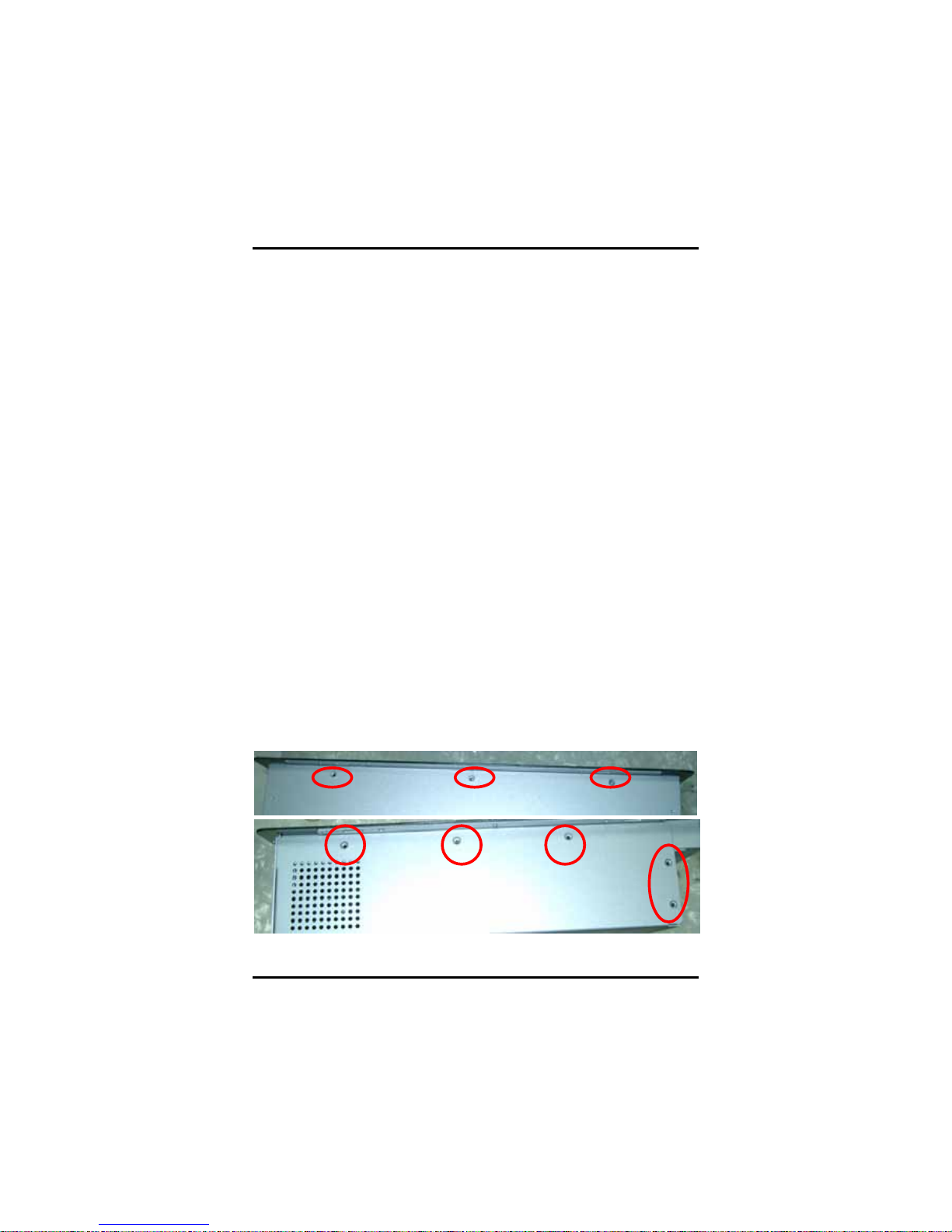
When upgrading the CPU, DRAM, please refer to the following
instructions and illustration:
1. Unscrew screws to remove the rear chassis.
Up side
Left / Right si de
Page 18
PANEL5155-807 User’s Manual
Hardware Installation
9
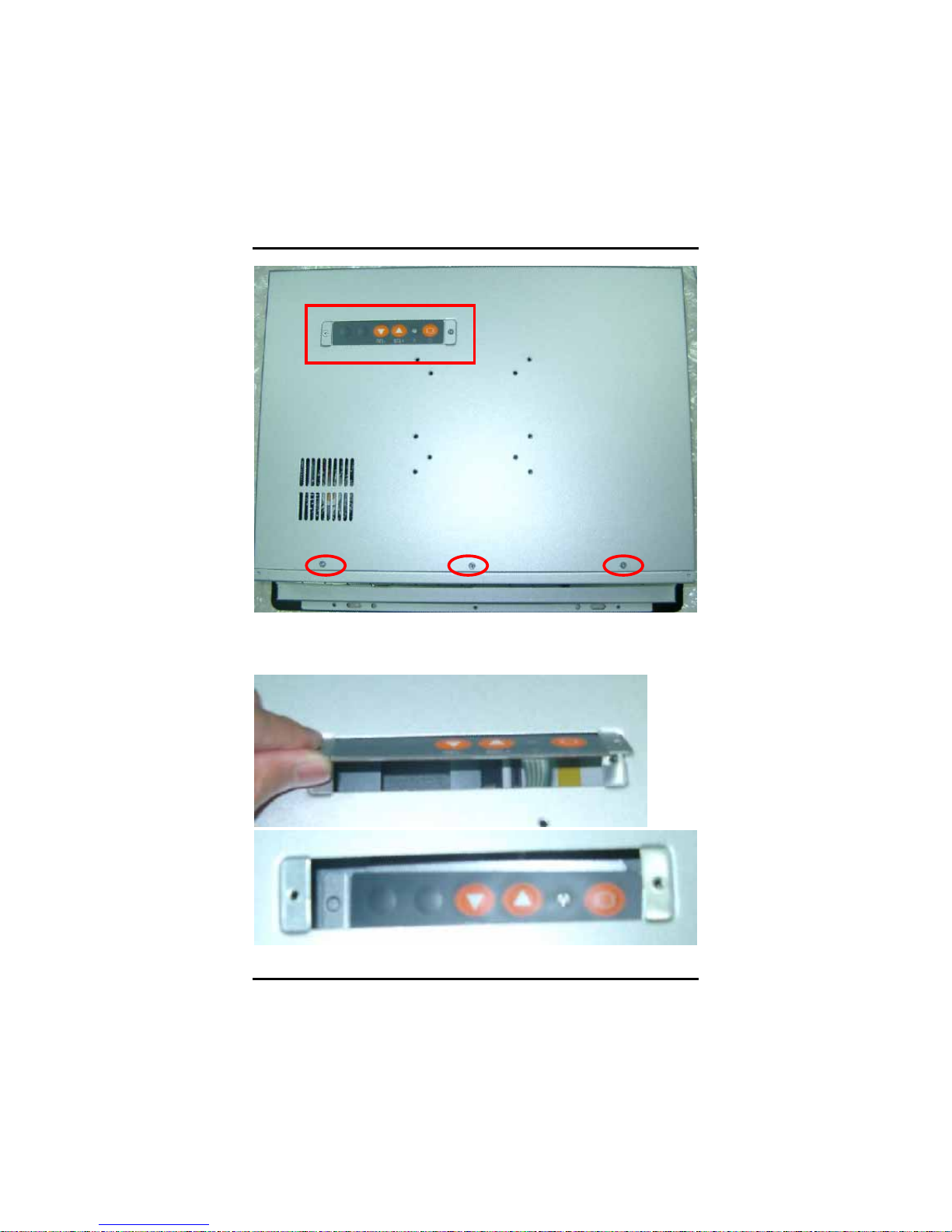
2. Please be careful of membrane switch and follow below photos
against cable broken.
Rear side
Page 19
PANEL5155-807 User’s Manual
Hardware Installation
10
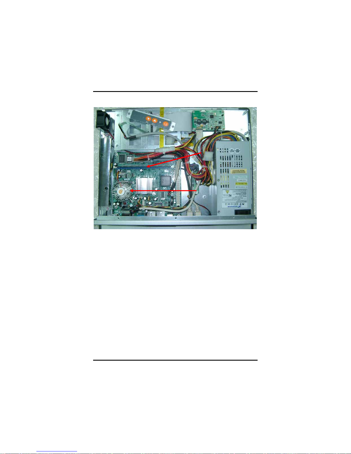
3. Install the CPU and DDR DRAM in the PANEL5155-807.
DRAM
CPU
Page 20
PANEL5155-807 User’s Manual
Hardware Installation
11
2.2 HDD Installation
The PANEL5155-807 offers a convenient drive bay m odule for users
to install HDD. The PANEL5155-807 offers one 3.5” HDD drive for
users to install. Please follow the steps:
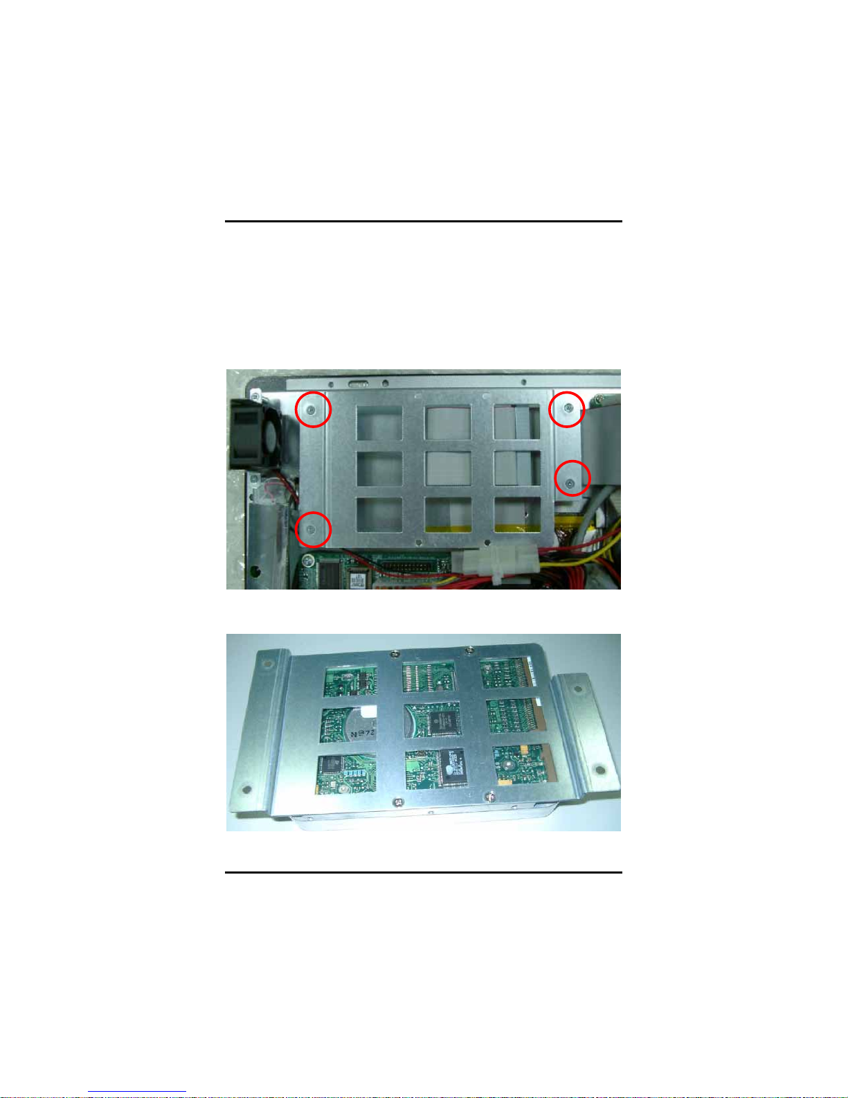
1. Unscrew screws to remove the rear chassis.
2. Unscrew 4 screws from the HDD drive bracket, and take out HDD
bracket kit to install 3.5” HDD.
3. Installation complete.
Page 21
PANEL5155-807 User’s Manual
Hardware Installation
12
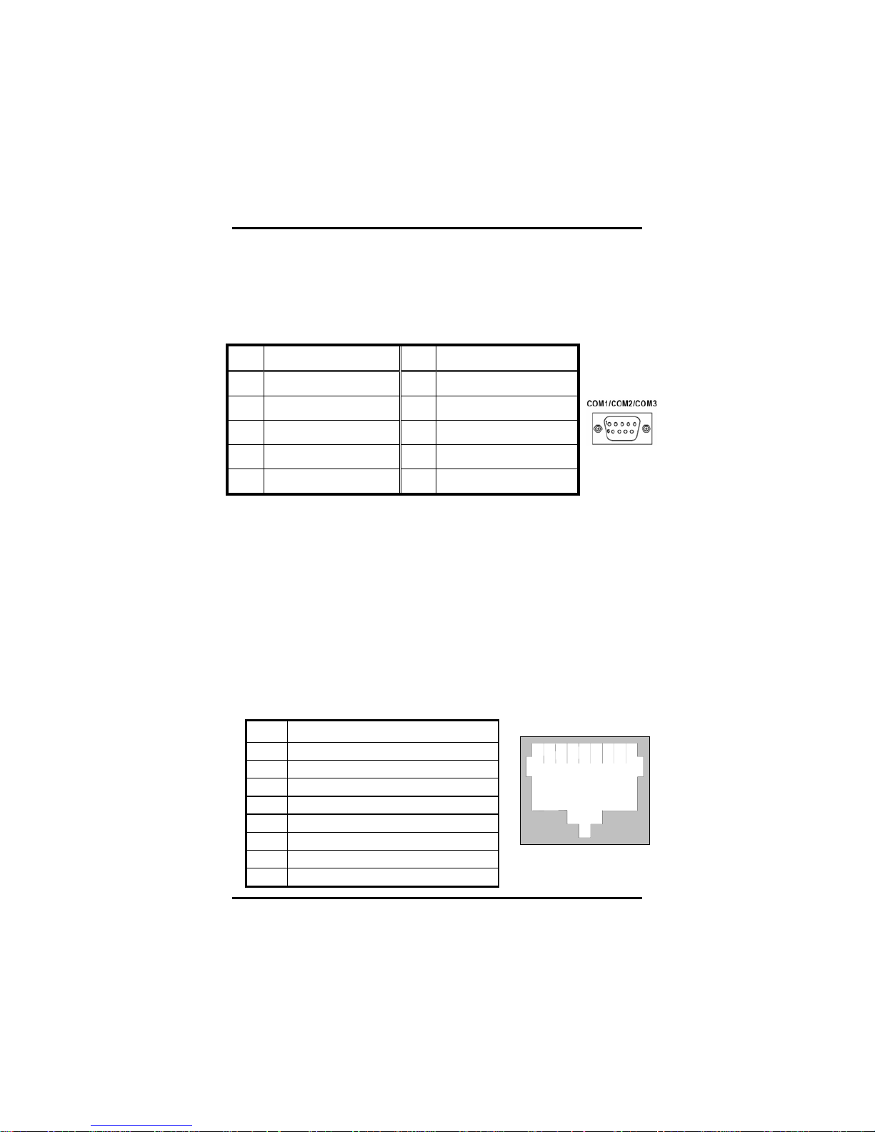
2.3 Serial Port Interface
The PANEL5155-807 has four onboard serial ports, COM1, COM2,
COM3, COM4 are RS-232 Port Connector.
The connector, COM1, COM2, COM3 are DB-9 connector, and the
following table shows the pin assignments of this connector.
Pin Signal Name Pin Signal Name
1 DCD, Data carrier detect 6 DSR, Data set ready
2 RXD, Receive data 7 RTS, Request to send
3 TXD, Transmit data 8 CTS, Clear to send
4 DTR, Data terminal ready 9 RI/+5V/+12V Ring indicator
5 GND, ground
2.4 VGA
The PANEL5155-807 has an analog RGB interface connector. It is
able to connect to an expansion CRT monitor, and the system can
display on both the flat panel and the CRT simultaneously.
2.5 Ethernet
The PANEL5155-807 provides an NE2000 compatible Ethernet
(RJ-45) interface. For network connection, just plug in one cable end
of the PANEL5155-807 10/100/1000-Base-T Hub into the standard
RJ-45 connector. The pin assignment of the RJ-45 is listed below;
RJ-45 Connector Pi n Assignment
Pin Signal
1 T X+ (Data transmission positive
2 T X- (Data transmission negative)
3 R x+(Data reception positive)
4 RJ45 t ermination
5 RJ45 t ermination
6 R x- (Data rec eption ne gative)
7 RJ45 t ermination
8 RJ45 t ermination
1
234567
8
RJ-45
Page 22
PANEL5155-807 User’s Manual
Hardware Installation
13
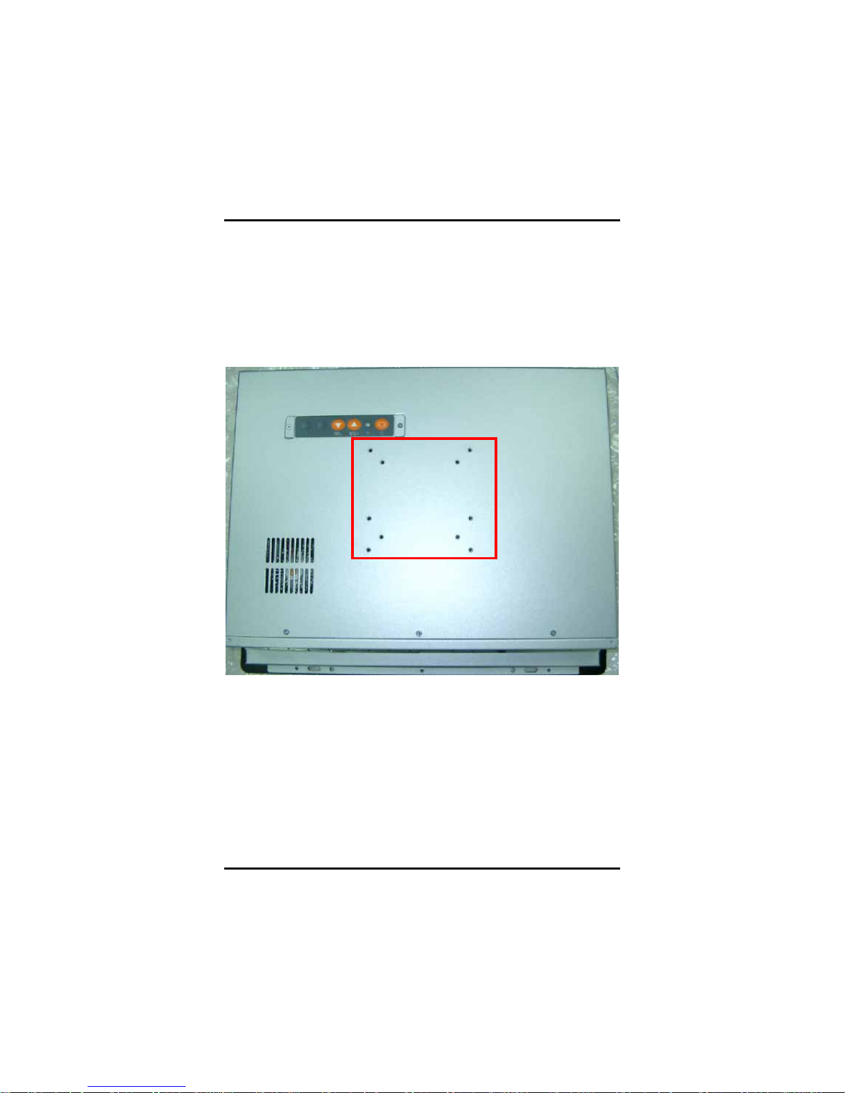
2.6 Mountings: VESA/ Wall/ Panel mount
There are four application options for the PANEL5155-807, VESA/
Wall/ Panel mountings.
2.6.1 VESA ARM
The PANEL5155-807 provides two ways for VESA mount: 75x75 mm
and 100x100 mm.
Page 23

PANEL5155-807 User’s Manual
Hardware Installation
14
2.6.2 Wall Mount
The PANEL5155-807 is designed for Wall mount application. The
standard set of desktop kit is included in the system packaging.
Please refer to the following figure.
1. Screw 4 screws to fix wall mount bracket.
2. Complete.
Page 24

PANEL5155-807 User’s Manual
Hardware Installation
15
2.6.3 Panel-Mount Kit Assembly
The PANEL5155-807 is designed for panel mount application. To
mount the PANEL5155-807, the standard set of mounting kit (included
in the system packaging) is needed.
Page 25

PANEL5155-807 User’s Manual
Driver Installation
16
C h a p t e r 3
Driver Installation
3.1 System
PANEL5155-807 could support with Windows 2000/XP. To facilitate
installation system driver, you should read the instructions in this
chapter carefully before you attempt installation.
1. Panel series\P5155-807\Driver
2. Select all files and follow the install procedure and press OK.
Page 26

PANEL5155-807 User’s Manual
Driver Installation
17
3.2 P5155-807S Touch Screen
3.2.1 Specification
Touch Screen:
ELO Surface Wave type
Touch Screen Controller:
D68054
Communications:
RS-232
Baud Rate:
9600 (default) and 19200
Resolution:
4096 x 4096, size independent
Power Input:
+5Vdc, nominal (+4.75 to +5.25 Vdc)
Positional Accuracy:
Less than 0.080 inch (2.03 mm)
Board Size:
8.38 x 5.33 cm
Touch Activation Force:
Typically less than 3 ounces (85 grams)
Page 27

PANEL5155-807 User’s Manual
Driver Installation
18
3.2.2 Driver Installation- Windows2000/XP
The touch screen of PANEL5155-807S provides a driver for use with
Windows 2000/XP. To facilitate installation of the touch screen driver,
you should read the instructions in this chapter carefully before you
attempt installation.
1. Insert Driver CD and select the “Panel series\P5155-807S\Driver
\Step5 - Touch.
2. Follow the install procedure and press OK.
3. Open “Control Panel” and you can see the icon, “ELO
touchscreen”.
Notice: Please choose COM4 for touch screen installed.
Page 28

PANEL5155-807 User’s Manual
Driver Installation
19
Page 29

PANEL5155-807 User’s Manual
Driver Installation
20
4. Calibration:
To adjust the display with touch panel, click “Align” and follow the
calibrate point to do calibration; there are three points on screen for
calibration.
5. Press YES.
Page 30

PANEL5155-807 User’s Manual
Driver Installation
21
3.3 P5155-807R Touch Screen
3.3.1 Specification
Touch Screen:
For 5-wire Analog Resistive type
Touch Screen Controller:
DMC9000
Communications:
RS-232
Baud Rate:
19200 baud rate fixed
Resolution:
1024 x 1024 (10 bit A/D converter inside)
Power Input:
5V to 12V DC
Power Consumption:
12V: 27mA+ i where (i = v/touch screen sheet R)
5V: 23mA+ i where (i = v/touch screen sheet R)
Board Size:
6.0 x 2.0 cm
Portrait:
Support 90o to 270o screen rotation
Static Protection:
ESD device option
Others:
Touch activate indication LED on board
Page 31

PANEL5155-807 User’s Manual
Driver Installation
22
3.3.2 Driver Installation- Windows2000/XP
The touch screen of PANEL5155-807R provides a driver for use with
Windows 2000/XP. To facilitate installation of the touch screen driver,
you should read the instructions in this chapter carefully before you
attempt installation.
1. Insert Driver CD and select the “Panel series\P5155-807R\Driver
\Step5 - Touch.
2. Follow the install procedure and press OK.
3. Click Start menu and select “PenMount Utilities”. You can see
PenMount Control Panel.
Notice: Please choose COM4 for touch screen installed.
Page 32

PANEL5155-807 User’s Manual
Driver Installation
23
4. Select the “Standard Calibrate” tab
Page 33

PANEL5155-807 User’s Manual
Driver Installation
24
5. Calibration:
To adjust the display with touch panel, click “Calibration” and follow
the calibrate point to do calibration; there are five points on screen for
calibration.
6. Press OK.
3.3.3 Driver Installation- DOS
Using “INSTALL.EXE” utility to install PenMount
software driver.
1. Insert Driver CD and select the Panel
series\P5155-807R\Driver\Step5 - Touch\Driver\DOS\Setup.exe
2. Press ENTER key to install the drivers to drive C or use
keyboard to key-in the hard disc drive that you plan to install the
driver.
3. The driver will ask “Do you want to modify your Autoexec.bat to
initialize PenMount? (Y/N)” Suggest you choose “YES” for
generating the initialization instructions in AUTOEXEC.BAT files.
Then follow up the instructions to complete the installation.
Page 34

PANEL5155-807 User’s Manual
Driver Installation
25
Identify the communication port and IRQ number
1. For the first time installation, or changing PenMount Touch
Screen’s COM port, use PMDETECT (e.g.
C:\PENMOUNT\PMDETECT) to check the COM port and IRQ
number. PMDETECT will save the correct data to PMOUSE.CFG
file for further use.
The driver detects your communication COM port and IRQ number
from COM1 IRQ4, COM2 IRQ3, COM3…. to COM4 IRQ15.
PenMount driver can find the COM port and IRQ number
automatically. The screen will then show:
PenMount is initialized successfully!!!
Create file “pmouse.cfg”. Success.
PenMount internal settings:
Comm. Port: COM<n> IRQ<n>
..........
1. PMDETECT pr ogram is able to skip the IRQ number detecting if
you Touchscreen Driver Installation 13 do not need to detect the
specified IRQ number. For example, you do not need to detect
IRQ5, and the command is:
C:\PENMOUNT\PMDETECT -N5
If you do not need to detect IRQ5 and IRQ9, the command is:
C:\PENMOUNT\PMDETECT -N5 -N9
Do Calibration
1. To adjust the touch screen mapping properly to display screen,
use PM.BAT (C:\PENMOUNT\PM) to do calibration. Choose “1”
DO CALIBRATION (adjust screen mapping).
2. The message on screen asks you to s elect video mode number.
Select
by keyboard to start the calibration, touch the upper-center point, then
right-center point, bottom-center point and left-center point in
sequence. After calibration, the data is shown in the screen, press any
key to continue the progress.
3. After the calibration, suggest you to test touch screen and display
Page 35

PANEL5155-807 User’s Manual
Driver Installation
26
mapped results by choose “3” DRAWING TEST under PM.BAT
Initializing the PenMount dr iver
If you don’t have the initialization commands in AUTOEXEC.BAT,
initialize PenMount C:\PENMOUNT\PMINIT) controller before you use
the PenMount Touch Screen. The display will show the initialization
message:
PenMount V7.06 Copyright(c) SALT International Corp.
Test:COM<n> IRQ<n> (<n> is the number after PMDETECT done)
PenMount communication settings: COM<N> IRQ<n> Baud Rate:
<xxxx>
... ... ... ... ... ... ... ... ... ...
Demonstration
To demonstrate or test touch screen operation, selecting “3”
DRAWING
TEST in PM.BAT file of Utility Directory. Drawing on screen.The other
demonstration program called “ICECREAM.EXE” in the
“PENMOUNT” directory can also be applied.
Page 36

PANEL5155-807 User’s Manual
Driver Installation
27
This page does not contain any information.
Page 37

PANEL5155-807 User’s Manual
Embedded O.S. Installation
28
C h a p t e r 4
Embedded O.S. Installation
4.1 Windows XP Embedded
Supported devices are as follows:
Multiple I/O: 3 x UARTs compliant Serial Port s (No
COM Mouse support)
IDE: IDE HDD
USB 2.0: 4 x USB Ports
Keyboard & Mouse: PS/2 Keyboard
PS/2 Mouse
Display: 800x600
1024x768 (default)
Ethernet: Fast Ethernet LAN
Gigabit Ethernet LAN
Audio: Line-out
MIC-in
SSD: CompactFlash™
Touch Sc reen: Surface Wave or 5-wire Resistive type
Page 38

PANEL5155-807 User’s Manual
Embedded O.S. Installation
29
4.1.1 Calibration Touch Screen for P5155-807S
This image includes a Touch Screen on COM4. To calibrate it,
do the following steps:
1. Start\Programs\Elo Calibration
2. Follow the on-screen direction s
3. Save the registry and restart the system
4.1.2 Calibration Touch Screen for P5155-807R
This image includes a Touch Screen on COM4, which is disabled by
default.
Before you can use and calibrate it, you should :
1. Set up PenMount touch device driver by executing
c:\Program Files\PenMount\setup.exe. When installation is
finished, an icon “PM” appears on the Taskbar.
2. Calibrate PenMount touch by clicking on “PM” icon and doing
calibration.
3. Restart computer.
Page 39

PANEL5155-807 User’s Manual
Embedded O.S. Installation
30
4.2 Windows CE.NET 5.0
Supported devices are as follows:
System Memory Support 128MB
256MB
Multiple I/O Parallel Port
4 x UARTs compliant Serial Ports (No
COM Mouse support)
IrDA Port
USB 2.0 4 x USB Host Ports
Keyboard & Mouse PS/2 Keyboard
PS/2 Mouse
Display (MS Flat) 800 x 600
1024 x 768
1280 x 1024
Ethernet Realtek RTL8100C
Audio Line-out
Speaker-out
MIC-in
SSD CompactFlash™
Touch Screen Surface Wave or 5-wire Resistive type
4.2.1 Calibration Touch Screen for P5155-807S
This image includes a Touch Screen on COM4. To calibrate it,
do the following steps:
1. Start\Programs\ELO Calibration
2. Follow the on-screen direction s
3. Save the registry and restart the system
4.2.2 Calibration Touch Screen for P5155-807R
In this image, we add PenMount Touch drivers and utilities.
To calibrate it, please Click “Start\Programs\PenMount Touch
Panel\Calibration” menu item
Page 40

PANEL5155-807 User’s Manual
Appendix
31
A p p e n d i x A
SBC86807 BIOS Setup
Appendix A describes the different settings available in the Award
BIOS that comes with the SBC86807 CPU card. Also, the instructions
on how to set up the BIOS configuration are contained in this chapter.
A.1 BIOS Introduction
The Award BIOS (Basic Input/Output System) installed in the system
ROM supports Intel Celeron processors in a standard IBM-AT
compatible I/O system. The BIOS provides critical low-level support
for standard devices such as disk drives, serial and parallel ports. It
also adds virus and password protection as well as special support for
detailed fine-tuning of the chipset controlling the entire system.
A.2 BIOS Setup
The Award BIOS provides a Setup utility program for specifying the
system configurations and settings. The BIOS ROM of the system
stores the Setup utility. When the computer is turned ON, the Award
BIOS is immediately activated. The following message will appear
on the screen:
Press <DEL> to Enter Setup
Then, press the <Del> key immediately to enter the Setup utility. The
delay of pressing the <Del> key will cause POST (Power On Self Test)
to continue with the test routines, thus preventing invoking the Setup.
In this case, the system has to be restarted for entering the BIO setup
by pressing the ”Reset” button or simultaneously pressing the <Ctrl>,
<Alt> and <Delete> keys. Besides, turnin g the system OFF first and
then ON again can also restart the system.
When entering the Setup utility, the Main Menu screen will appear on
the screen. Various setup functions and exit choices can be selected
from this menu.
Page 41

PANEL5155-807 User’s Manual
Appendix
32
In general, the arrow keys are used to highlight items, <Enter> to
select, the <PgUp> and <PgDn> keys to change entries, <F1> for
help and <Esc> to quit.
Phoenix – AwardBIOS CMOS Setup Utility
` Standard CMOS Features ` Frequency/Voltage Control
` Advanced BIOS Features
Load Optimized Defaults
` Advanced Chipset Features
Set Supervisor Password
` Integrated Peripherals
Set User Password
` Power Management Setup
Save & Exit Setup
` PnP/PCI Configurations
Exit Without Saving
` PC Health Status
Esc : Quit
Ç È Æ← : Select Item
F10 : Save & Exit Setup
Time, Date, Hard Disk Type…
The section below the setup items in the Main Menu displays the
control keys for this menu. Another section located at the bottom of
the Main Menu, just below the control keys section, displays
information on the currently highlighted item in the list.
NOTE:
If the computer cannot boot after making and saving system
changes with Setup, the Award BIOS, via its built-in override
feature, resets your system to the CMOS default settings.
Avoid making any changes to the chipset defaults are strongly
recommended. These defaults have been carefully chosen by both
Award and the system manufacturer to provide the absolute maximum
performance and reliability.
Page 42

PANEL5155-807 User’s Manual
Appendix
33
A.2.1 Standard CMOS Setup
“Standard CMOS Setup” is used to record some basic hardware
configurations in the computer system and set the system clock and
error handling. If the motherboard is already installed in a working
system, there is no need to enter this option . However, the Standard
CMOS option has to be setup in any of the following situations: the
system hardware configurations are changed, the onboard battery
fails, and the configuration stored in the CMOS memory is lost or
damaged.
Phoenix – Award BIOS CMOS Setup Utility
Standard CMOS Features
Date (mm:dd:yy) Thu, Jun 29 2006 Item Help
Time (hh:mm:ss) 13 : 9 : 11
Menu Level
f
f IDE Primary Master
None
f IDE Primary Slave
None Change the
f IDE Secondary Master
None Day, month,
f IDE Secondary Slave
None Year and
Century
Drive A None.
Drive B None
Video EGA/VGA
Halt on All, But keyboard
Base Memory 640K
Extended Memory 521216K
Total Memory 522240K
ÇÈÆÅ : Move Enter: Select +/-/PU/PD: Value F10: Save ESC: Exit
F1: General Help
F5: Previous Values F6: Fail-Safe Defaults F7: Optimized Defaults
At the bottom of the menu are the control keys for the use of this
menu. The <F1> key can be pressed in each item field to display the
relevant information for help. The memory display at the lower
right-hand side of the menu is read-only. It will adjust automatically
according to the memory changed. The following pages describe each
item of this menu.
Page 43

PANEL5155-807 User’s Manual
Appendix
34
Date
The date format is <day>, <date> <month> <year>. Press <F3> to
show the calendar.
day
The day of week, from Sun to Sat, determined by
the BIOS, is read only
date
The date, from 1 to 31 (or the maximum allowed
in the month), can key in the numerical / function
key
month The month, Jan through Dec.
year The year, depen ds on the yea r of BIOS
Time
The time format is <hour> <minute> <second> accepting either function
key or numerical key. The time is calculated based on the 24-hour
military-time clock. For example, 1 p.m. is 13:00:00.
IDE Primary Master / Primary Slave / Secondary Master / Secondary
Slave
This category identifies the type of the channel that is installed in the
computer. There are 45 predefined types and 2 user definable types for
Enhanced IDE BIOS. Type 1 to Type 45 are predefined. Type User is
user-definable.
Press <PgUp>/<+ > or <PgDn>/<−> to select a numbered hard disk type
or type the number and press <Enter>. Note that the specifications of
the drive in the system must match with the drive table. T he hard disk
will not work properly if the impr oper information within this category is
entered. If the disk drive type does not match or is not listed, the Type
User is used to define the drive type manually.
If the Type User is selected, related information has to be entered.
Enter the information directly from the keyboard and press <Enter>.
This information should be provided in the documentation from the hard
disk vendor or the system manufacturer.
If the controller of HDD interface is ESDI, select “Type 1”.
If the controller of HDD interface is SCSI, select “None”.
If the controller of HDD interface is CD-ROM, select “None”.
CYLS.
number of
cylinders
LANDZONE landing zone
HEADS
number of
heads
SECTORS
number of
sectors
PRECOMP write precom MODE
HDD access
mode
Page 44

PANEL5155-807 User’s Manual
Appendix
35
If there is no hard disk drive installed, select NONE and press <Enter>.
Drive A type/Drive B type
The category identifies the types of floppy disk drive A or drive B installed
in the computer.
None No floppy drive installed
360K, 5.25 in
5.25 inch PC-type standard drive; 360Kb
capacity
1.2M, 5.25 in
5.25 inch AT-type high-density drive;
1.2MB capacity
720K, 3.5 in
3.5 inch double-sided drive; 720Kb
capacity
1.44M, 3.5 in
3.5 inch double-sided drive; 1.44MB
capacity
2.88M, 3.5 in
3.5 inch double-sided drive; 2.88MB
capacity
Select Display Device
This item selection includes EGA/VGA, CGA 40, CGA 80 and MONO.
Halt On
This field determines whether the system will halt if an error is detected
during power up.
No errors
The system boot will halt on any
error detected. (default)
All errors
Whenever the BIOS detects a
non-fatal error, the system will stop
and you will be prompted.
All, But Keyboard
The system boot will not stop for a
keyboard error; it will stop for al l
other errors.
All, But Diskette
The system boot will not stop for a
disk error; it will stop for all other
errors.
All, But Disk/Key
The system boot will not stop for a
keyboard or disk error; it will stop
for all other errors.
Page 45

PANEL5155-807 User’s Manual
Appendix
36
A.2.2 Advanced BIOS Features
This section is used to configure and improve the system and set up
some system features according to the user’s preference.
Phoenix – Award BIOS CMOS Setup Utility
Advanced BIO S Features
Hard Disk Boot Priority Press Enter Item Help
Virus Warning Disabled
CPU L1 & L2 Cache Enabled Menu Level f
Quick Power On Self Test Enabled
First Boot Device Enabled
Second Boot Device Enabled
Third Boot Device Enabled
Boot Other Dev ice Enabled
Onboard Lan Boot ROM Disabled
Swap Floppy Drive Disabled
Boot Up Floppy Seek Disabled
Boot Up NumLo ck Status On
Gate A20 Option Fast
Typematic Rate Setting Enabled
Typematic Rate (Chars/Sec) 30
Typematic Delay (Msec) 250
Security Option Setup
APIC Mode Enabled
MPS Version Control For OS 1.4
Small Logo(EPA) Show Enabled
Select Hard
Disk Boot
Device Priority
ÇÈÆÅ : Move Enter: Select +/-/PU/PD: Value F10: Save ESC: Exit
F1: General Help
F5: Previous Values F6: Fail-Safe Defaults F7: Optimized Defaults
Page 46

PANEL5155-807 User’s Manual
Appendix
37
Virus Warning
This item protects the boot sector and partition table of the hard disk
against accidental modifications. If an attempt is m ade, the BIOS will halt
the system and display a warning message. If this occurs, the user can
either continue the operation or run an anti-virus program to locate and
remove the problem.
NOTE: Many disk diagnostic programs, which attempt to access
the boot sector table, can cause the virus warning. Thus,
disable the Virus Warning feature while running any of
these programs..
CPU L1 & L2 Cache
Cache memory is additional memory that is much faster than
conventional DRAM (system memory). CPUs from 486-type and up
contain internal cache memory, and most, but not all, modern PCs have
additional (external) cache memory. When the CPU requests data, the
system transfers the requested data from the main DRAM into cache
memory, for even faster access by the CPU. These items are used to
enable (speed up memory access) or disable the cache function. By
default, these are Enabled.
Quick Power On Self Test
This option speeds up Power On Self Test (POST) after turning on the
system power. If it is set as Enabled, BIOS will shorten or skip some
check items during POST. The default setting is “Enabled”.
Enabled Enable Quick POST
Disabled Norm al POST
First/Second/Third Boot Device
These items allow th e selection of the 1st, 2nd, and 3rd devices that the
system will search for during its boot-up sequence. The wide range of
selection includes Floppy, LS120, ZIP100, HDD0~3, SCSI, and CDROM.
Boot Other Device
This item allows the user to enable/disable the boot device not listed on
the First/Second/Third boot devices option above. The default setting is
Enabled.
Swap Floppy Drive
This allows you to det erm ine w heth er t o ena bl e Swa p Flo pp y Driv e or no t.
When enabled, the BIOS swaps floppy drive assignments so that Drive A
becomes Drive B, and Drive B becomes Drive A. By default, this field is
set to “Disabled”.
Boot Up Floppy Seek
Page 47

PANEL5155-807 User’s Manual
Appendix
38
During POST, BIOS will determine the f loppy disk drive type, 40 or 80
tracks. 360Kb type is 40 tracks while 720Kb, 1.2MB and 1.44MB are all
80 tracks. The default value is “Enabled”.
Enabled
BIOS searches for floppy disk drive to determine if it is
40 or 80 tracks. Note that BIOS can not tell from 720K,
1.2M or 1.44M drive type as they are all 80 tracks.
Disabled
BIOS will not search for the type of floppy disk drive by
track number. There will be no warning message
displayed if the drive installed is 360K.
Boot Up NumLock Status
This option enables and disables the number lock function of the keypad.
The default value is “On”.
On Keypad functions confine with numbers
Off
Keypad functions convert to special functions (i.e.,
left/right arrow keys)
Gate A20 Option
The default value is “Fast”.
Normal
The A20 signal is controlled by keyboard controller
or chipset hardware.
Fast
Default: Fast. The A20 signal is controlled by Port
92 or chipset specific method.
Typematic Rate Setting
This determines the typematic rate of the keyboard. The default value is
“Disabled”.
Enabled
Enable typematic rate and typematic delay
programming
Disabled
Disable typematic rate and typematic delay
programming. The system BIOS will use default value
of these 2 items and the default is controlled by
keyboard.
Typematic Rate (Chars/Sec)
This option refers to the number of characters the keyboard can type per
second. The default value is “6”.
6 6 characters per second
8 8 characters per second
10 10 characters per second
12 12 characters per second
Page 48

PANEL5155-807 User’s Manual
Appendix
39
15 15 characters per second
20 20 characters per second
24 24 characters per second
30 30 characters per second
Typematic Delay (Msec)
This option sets the display time interval from the first to the second
character when holding a key. The default value is “250”.
250 250 msec
500 500 msec
750 750 msec
1000 1000 msec
Security Option
This item limits the access to the system and Setup, or just to Setup.
The default value is “Setup”.
System
The system will not boot and access to Setup will be
denied if the incorrect password is entered at the prompt.
Setup
The system will boot, but access to Setup will be denied
if the correct password is not entered at the prompt.
NOTE: To disable security, select PASSWORD SETTING at
Main Menu and then password is asked to enter. Do
not type anything, just press <Enter> and it will disable
security. Once the security is disabled, the system will
boot and you can enter Setup freely.
Page 49

PANEL5155-807 User’s Manual
Appendix
40
A.2.3 Advanced Chipset Features
Since the features in this section are related to the chipset on the
CPU board and are completely optimized, changing the default
settings in this setup table are not recommended unless the user is
well oriented with the chipset features.
Phoenix – Award BIOS CMOS Setup Utility
Advanced Chipse t Features
DRAM Timing By SPD B y SPD Item Help
X CAS Latency Time 2
X Active to Precharge Delay 5
X DRAM RAS# to CAS# Delay 3 Menu Level f
X DRAM RAS# Precharge 3
DRAM Data Integrity Mode Non-ECC
MGM Core Frequency Auto Max
400/333MHz
System BIOS Cacheable Enabled
Video BIOS Cacheable Enabled
Memory Hole At 15M-16M Disabled
Delayed Transaction Enabled
Delayed Prior to Thermal 16 Min
AGP Aperture Size (MB) 64
** On-Chip VGA Setting **
On-Chip VGA Enabled
On-Chip Frame Buffer Size 1 MB
Boot Display CRT + LFP
Panel Scaling Auto
Panel Type 1024x768 24Bit
ÇÈÆÅ : Move Enter: Select +/-/PU/PD: Value F10: Save ESC: Exit
F1: General Help
F5: Previous Values F6: Fail-Safe Defaults F7: Optimized Defaults
Page 50

PANEL5155-807 User’s Manual
Appendix
41
DRAM Timing By SPD
This item is selected depending on whether the board has paged
DRAMs or EDO (extended data output) DRAMs.
System BIOS Cacheable
Selecting “Enabled” allows caching of the system BIOS ROM at
F0000h-FFFFFh, resulting in better system performance. However, if any
program writes to this memory area, a system error may result.
The choice: Enabled, Disabled.
Video BIOS Cacheable
Selecting “Enabled” allows caching of the A/B segment, resulting in better
system performance.
The choice: Enabled, Disabled.
Memory Hole At 15M-16M
To improve performance, certain space in memory is reserved for ISA
cards. This memory must be mapped into the memory space below
16MB. The available choices are Enabled and Disabled.
Delay Transaction
The chipset has an embedded 32-bit posted write buffer to support delay
transactions cycles. Select “Enabled” to support compliance with PCI
specification version 2.1.
AGP Aperture Size (MB)
The field sets aperture size of the graphics. The aperture is a portion of
the PCI memory address range dedicated for graphics memory address
space. Host cycles that hit the aperture range are forwarded to the AGP
without any translation. The options available are 4M, 8M, 16M, 32M,
64M, 128M and 256M.
Page 51

PANEL5155-807 User’s Manual
Appendix
42
A.2.4 Integrated Peripherals
This option sets the hard disk configuration, mode and port.
Phoenix – Award BIOS CMOS Setup Utility
Integrated Peripherals
¾ OnChip IDE Device Enabled Item Help
¾ Onboard Device Enabled
¾ SuperIO Device Enabled Menu Level f
Onboard UART 3 3E8
Onboard UART 3 IRQ IRQ10
Onboard UART 4 2E8
Onboard UART 4 IRQ IRQ11
ÇÈÆÅ : Move Enter: Select +/-/PU/PD: Value F10: Save ESC: Exit
F1: General Help
F5: Previous Values F6: Fail-Safe Defaults F7: Optimized Defaults
Phoenix – Award BIOS CMOS Setup Utility
OnChip IDE Device
OnChip Primary PCI IDE Enabled Item Help
IDE Primary Master PIO Auto
IDE Primary Slave PIO Auto Menu Level f
IDE Primary Master UDMA Auto
IDE Primary Slave UDMA Auto
OnChip Secondary PCI IDE Enabled
IDE Secondary Master PIO Auto
IDE Secondary Slave PIO Auto
IDE Secondary Master UDMA Auto
IDE Secondary Slave UDMA Auto
IDE DMA transfer access Enabled
IDE HDD Block Mode Enabled
ÇÈÆÅ : Move Enter: Select +/-/PU/PD: Value F10: Save ESC: Exit
F1: General Help
F5: Previous Values F6: Fail-Safe Defaults F7: Optimized Defaults
Page 52

PANEL5155-807 User’s Manual
Appendix
43
Phoenix – Award BIOS CMOS Setup Utility
Onboard Device
USB controller Enabled Item Help
USB 2.0 controller Enabled
USB Keyboard Support Enabled Menu Level f
USB Mouse Support Disabled
AC 97 Audio Auto
Init Display first Onboard/AGP
ÇÈÆÅ : Move Enter: Select +/-/PU/PD: Value F10: Save ESC: Exit
F1: General Help
F5: Previous Values F6: Fail-Safe Defaults F7: Optimized Defaults
Phoenix – Award BIOS CMOS Setup Utility
SuperIO Devi ce
Onboard FDC Controller Enabled Item Help
Onboard Serial Port 1 3F8/IRQ4
Onboard Serial Port 2 2F8/IRQ3 Menu Level f
Onboard Parallel Port 378/IRQ7
Parallel Port Mode ECP+EPP
EPP Mode Select EPP1.9
ECP Mode Use DMA 3
PWRON After PWR-Fail Off
ÇÈÆÅ : Move Enter: Select +/-/PU/PD: Value F10: Save ESC: Exit
F1: General Help
F5: Previous Values F6: Fail-Safe Defaults F7: Optimized Defaults
OnChip Primary/Secondary PCI IDE
The integrated peripheral controller contains an IDE interface with
support for two IDE channels. Select Enabled to activate each channel
separately. The default value is “Enabled”
NOTE: Choosing Disabled for these options will automatically remove the
IDE Primary Master/Slave PIO and/or IDE Secondary Master/Slave PIO
items on the menu.
IDE Primary/Secondary Master/Slave PIO
Page 53

PANEL5155-807 User’s Manual
Appendix
44
The four PIO (Programmed Input/Output) fields sets a PIO mode (0-4) for
each of the four IDE devices that the onboard IDE interface supports.
Modes 0 through 4 provide successively increased performance. In
Auto mode, the system automatic ally determi nes the best mode for each
device. The choice: Auto, Mode 0, Mode 1, Mode 2, Mode 3, Mode 4.
IDE Primary/Secondary Master/Slave UDMA
Ultra DMA 66/100 implementation is possible only if your IDE hard drive
supports it and the operating environment includes a DMA driver
(Windows 98 or a third-party IDE bus master driver). If the hard drive and
the system software both support Ultra DMA 33/66/100, select Auto to
enable BIOS support. The Choice: Auto, Mode 0, Mode 1, Mode 2, Mode
3, Mode 4.
Init Display First
This item is to active whether PCI Slot or on-chip VGA first.
The choice: PCI Slot, Onboard/AGP.
Onboard FDC Controller
Select “Enabled” if the system has a floppy disk controller (FDC) installed
on the system board and the FDC will be used. If the and-in FDC are
installed or the system has no floppy drive, select “Disabled” in this field.
The choice: Enabled, Disabled.
Onboard Serial Port 1/Port 2
Select an address and corresponding interrupt for the first, second and
twist serial ports.
The choice: 3F8/IRQ4, 2E8/IRQ3, 3E8/IRQ4, 2F8/IRQ3, Disabled, Auto.
Onboard Parallel Port
This item is to determine access onboard parallel por t controller with
which I/O address.
The choice: 3BC/IRQ7, 378/IRQ7, 278/IRQ5, Disabled.
Parallel Port Mode
Select an operating mode for the onboard parallel (printer) port. Select
Normal, Compatible, or SPP unless you are certain yo ur hardware and
software both support one of the other available modes.
The choice: SPP, EPP, ECP, ECP+EPP.
ECP Mode Use DMA
Select a DMA channel for the parallel port for use during ECP mode.
The choice: 3, 1.
Page 54

PANEL5155-807 User’s Manual
Appendix
45
A.2.5 Power Management S etup
The Power Management Setup is to save energy of the system
effectively. It will shut down the hard disk and turn OFF video display
after a period of inactivity.
Phoenix – Award BIOS CMOS Setup Utility
Power Management Setup
ACPI Function Enabled Item Help
ACPI Suspend Type S1 & S3
Run VGABIOS if S3 Resume Auto Menu Level f
Power Management User Define
Video Off Method DPMS
Video Off In Suspend Yes
Suspend Type Sto p Grant
MODEM Use IRQ 3
Suspend Mode Disabled
HDD Power Down Disabled
Soft-Off by PWRBTN Instant-Off
Power On by Ring Enabled
Wake Up On LAN Ena bled
USB KB Wake-Up From S3 Disabled
Resume by Alarm Disabled
* Data(of Month ) Alarm 0
* Time(hh:mm:ss) Alarm 0 : 0 : 0
** Reload Global Timer Events **
Primary IDE 0 Disabled
Primary IDE 1 Disabled
Secondary IDE 0 Disabled
Secondary IDE 1 Disabled
FDD, COM, LPT Port Disabled
PCI PIRQ[A-D]# Disabled
ÇÈÆÅ : Move Enter: Select +/-/PU/PD: Value F10: Save ESC: Exit
F1: General Help
F5: Previous Values F6: Fail-Safe Defaults F7: Optimized Defaults
ACPI Function
This item is to enable/disable the Advanced Configuration and Power
Interface (ACPI).
The choice: Enabled, Disabled.
Power Management
This item is to select the Power Management mode.
Page 55

PANEL5155-807 User’s Manual
Appendix
46
The choice: User Define, Min Saving, Max Saving.
Video Off Method
This determines the manner in which the monitor is blanked.
V/H SYNC +
Blank
This causes the system to turn off the vertical and
horizontal synchronization ports and write blanks
to the video buffer.
DPMS
Select this option if your monitor supports the
Display Power Management Signaling (DPMS)
standard of the Video Electronics Standards to
select video power management values.
Blank Screen This option only writes blanks to the video buffer.
MODEM Use IRQ
APM 1.2 function used only.
The choice: NA, 3, 4, 5, 7, 9, 10, 11
Suspend Mode
After the selected period of system inactivity (1 minute to 1 hour), all
devices except the CPU shut off. The default value is “Disabled”.
Disabled
System will never enter SUSPEND mode.
1/2/4/6/8/10/20/30/40 Min/1 Hr
Defines the continuous idle time before the
system entering SUSPEND mode.
If any item defined in (J) is enabled &
active, SUSPEND timer will be reloaded.
HDD Power Down
After the selected period of drive inactivity (1 to 15 minutes), the hard
disk drive powers down while all other devices remain active. The default
value is “Disabled”.
Disabled
HDD’s motor will not power OFF
1/2/3/4/5/6/7/8/9/10/11/12/
13/14/15 Min
Defines the continuous HDD idle time
before the HDD enters power saving mode
motor OFF).
Soft-off by PWR-BTTN
This only works with the system using an ATX power supply. It also
allows user to define the type of soft power OFF sequence for the system
to follow.
Instant-Off
(default)
This option follows the conventional manner systems
perform when power is turned OFF. Instant-Off is a soft
power OFF sequence requiring only the switching of the
power supply button to OFF.
Page 56

PANEL5155-807 User’s Manual
Appendix
47
Delay 4 Sec.
Upon turning OFF system from the power switch, this
option will delay the complete system power OFF
sequence by approximately 4 seconds. Within this delay
period, system will temporarily enter into Suspend Mode
enabling you to restart the system at once.
Power On by Ring
This option allows the system to resume or wake up upon detecting any
ring signals coming from an installed modem. The default value is
“Enabled”.
Page 57

PANEL5155-807 User’s Manual
Appendix
48
A.2.6 PNP/PCI Configuration
This section describes the PCI bus system configuration. PCI or
Personal Computer Interconnect is a system which allows I/O devices
to operate at speeds nearing the speed of the CPU when
communicating with its own special components. This section covers
some very technical items, and it is strongly recommended tha t only
experienced users should make changes to the default settings.
Phoenix – Award BIOS CMOS Setup Utility
PnP/PCI Configurations
Reset Configurat ion Data Disabled
Item Help
Resources Controlled By Auto(ESCD) Menu Level f
X IRQ Resources Press Enter
PCI/VGA Palette Snoop Disabled
Select Yes if you are
using a Plug and play
capable operating
system select No if
you need the BIOS to
configure non-boot
devices
ÇÈÆÅ : Move Enter: Select +/-/PU/PD: Value F10: Save ESC: Exit
F1: General Help
F5: Previous Values F6: Fail-Safe Defaults F7: Optimized Defaults
Reset Configuration Data
Normally, this field is “Disabled”. Select “Enabled” to reset Extended
System Configuration Data (ESCD). When exiting Setup or installed a
new add-on, the system reconfiguration has caused such a serious
conflict that the operating system cannot boot. The options available are
Enabled and Disabled.
Resource controlled by
The Award Plug and Play BIOS has the capacity to automatically
configure all of the boot and the Plug and Play compatible devices.
However, this capability means absolutely nothing unless using a Plug
and Play operating system such as Windows®98. The options available
are Auto and Manual.
PCI/VGA Palette Snoop
Leave this field at “Disabled”.
The choice: Enabled, Disabled.
Page 58

PANEL5155-807 User’s Manual
Appendix
49
A.2.7 PC Health Status
This section is to monitor the current h ardware status of core voltages.
This is available only if there is hardware monitoring mechanism
onboard.
Phoenix – Award BIOS CMOS Setup Utility
PC Health Status
Current GMCH Temp.
Current CPU Temp.
Current System T emp.
Current CPU FAN Speed
Current System F AN Speed
Vcore
+ 12 V
VCC 5V
5VSB (V)
VCC 1.2V
VCC DIMM
ÇÈÆÅ : Move Enter: Select +/-/PU/PD: Value F10: Save ESC: Exit
F1: General Help
F5: Previous Values F6: Fail-Safe Defaults F7: Optimized Defaults
Current CPU Temperature
These read-only fields reflect the functions of the hardware thermal
sensor that monitors the chip blocks and system temperatures to ensure
the system is stable.
Current CPU/SYSTEM FAN S peed
These read-only fields show the current speeds in RPM (revolution per
minute) for the CPU fan and system fan by the hardware monitoring IC.
Page 59

PANEL5155-807 User’s Manual
Appendix
50
A.2.8 Frequency/Voltage Control
CMOS Setup Utility-Copyright © 1984-2001 Award Softw are
Frequency/ Voltage C ontrol
Auto Detect DIMM/PCI Clk Enabled
Spread Spectrum Disabled Menu Level f
ÇÈÆÅ : Move Enter: Select +/-/PU/PD: Value F10: Save ESC: Exit
F1: General Help
F5: Previous Values F6: Fail-Safe Defaults F7: Optimized Defaults
Auto Detect DIMM/PCI Clk
When enabled, this item will auto detect if the DIMM and PCI socket have
devices and will send clock signal to DIMM and PCI devices. When
disabled, it will send the clock signal to all DIMM and PCI socket.
The choice: Enabled, Disabled.
Spread Spectrum
This item is to enable/disable the spread spectrum modulate.
The choice: Enabled, Disabled.
Page 60

PANEL5155-807 User’s Manual
Appendix
51
A.2.9 Load Fail-Safe Defaults
This option is to load the troubleshooting default values permanently
stored in the BIOS ROM. These default settings are non-optimal and
disable all high-performance features.
Phoenix – Award BIOS CMOS Setup Utility
` Standard CMOS Features ` Frequency/Voltage Control
` Advanced BIOS Features
Load Fail-Safe Defaults
` Advanced Chipset Features
Load Optimized Defaults
` Integrated Peripherals
Set Supervisor Password
` Power Ma
` PnP/PCI C
Load Fail-Safe Defaults (Y/N)? N
` PC Health Status
Exit Without Saving
Esc : Quit Ç È Æ Å : Select Item
F10 : Save & Exit Setup
Load Fail-Safe Defaults
To load BIOS defaults value to CMOS SRAM, enter “Y”. If not, enter
“N”.
Page 61

PANEL5155-807 User’s Manual
Appendix
52
A.2.10 Load Optimized Defaults
This option is to load the default values to the system config uration.
These default settings are optimal and enable all high performance
features.
Phoenix – Award BIOS CMOS Setup Utility
` Standard CMOS Features ` Frequency/Voltage Control
` Advanced BIOS Features
Load Fail-Safe Defaults
` Advanced Chipset Features
Load Optimized Defaults
` Integrated Peripherals
Set Supervisor Password
` Power Man
` PnP/PCI Co
Load Optimized Defaults (Y/N)? N
` PC Health Status
Exit Without Saving
Esc : Quit Ç È Æ Å : Select Item
F10 : Save & Exit Setup
Load Optimized Defaults
To load SETUP defaults value to CMOS SRAM, enter “Y”. If not, enter
“N”.
Page 62

PANEL5155-807 User’s Manual
Appendix
53
A.2.11 Set Supervisor/User Password
Either supervisor or user password, or both of them can be set in this
option. The differences between them are:
1. supervisor password: can enter and change the options of the
setup menus.
2. user password: just can enter but do not have the right to
change the options of the setup menus.
When this function is selected, the following message will appear at
the center of the screen for creating a passw ord .
ENTER PASSWORD:
Type the password with eight characters at most, and press <Enter>.
The password typed will now clear any previously entered password
from CMOS memory. Then, confirm the password by typing the
password again and pressing <Enter>. Or, not enter a password and
abort the selection by pressing <Esc>.
To disable the password by pressing <Enter> without typing in any
password when the message “Enter Password” is showed. Then,
message below will appear to confirm that the password has been
disabled.
PASSWORD DISABLED.
Once the password is disabled, the system will boot and enter Setup
freely.
When a password is enabled, it has to be typed to enter the Setup
every time. This prevents any unauthorized person from changing the
system configuration.
Additionally when a password is enabled, the BIOS can also set to
request a password every time the system reboots. This would
prevent unauthorized use of the computer.
The user can determine when the password is required within the
BIOS Features Setup Menu and its Security option. If the Security
option is set to “System”, the password is required during boot up and
entry into Setup. If it set as “Setup”, prompting will only occur prior to
entering Setup.
Page 63

PANEL5155-807 User’s Manual
Appendix
54
A.2.12 Save & Exit Setup
This is to determine whether or not to accept the modifications. Typing
“Y” quits the setup utility and saves all changes into the CMOS
memory. Typing “N” brigs back to Setup utility.
Phoenix – Award BIOS CMOS Setup Utility
` Standard CMOS Features ` Frequency/Voltage Control
` Advanced BIOS Features
Load Fail-Safe Defaults
` Advanced Chipset Features
Load Optimized Defaults
` Integrated Peripherals
Set Supervisor Password
` Power Man
` PnP/PCI Con
SAVE to CMOS and EXIT (Y/N)? Y
` PC Health Status
Exit Without Saving
Esc : Quit Ç È Æ Å : Select Item
F10 : Save & Exit Setup
Save Data to CMOS
Page 64

PANEL5155-807 User’s Manual
Appendix
55
A.2.13 Exit Without Saving
Select this option to exit the Setup utility without saving the changes
made in this session. Typing “Y” will quit the Setup utility without
saving the modifications. Typing “N” will return to Setup utility.
Phoenix – Award BIOS CMOS Setup Utility
` Standard CMOS Features ` Frequency/Voltage Control
` Advanced BIOS Features
Load Fail-Safe Defaults
` Advanced Chipset Features
Load Optimized Defaults
` Integrated Peripherals
Set Supervisor Password
` Power Man
` PnP/PCI Con
Quit Without Saving (Y/N)? N
` PC Health Status
Exit Without Saving
Esc : Quit Ç È Æ Å : Select Item
F10 : Save & Exit Setup
Abandon all Datas
Page 65

PANEL5155-807 User’s Manual
Appendix
56
Appendix B
Power Supply Specification
B.1 Power Suppl y: FSP180-50PLA1 (180W,
AC 110~230V Input)
B.1.1 ELECTRICAL REQUIREMENTS
OUTPUT ELECTRICAL REQUIREMENTS
The subject power supply will meet all electrical specifications below,
over the full operation temperature range and dynamic load
regulation.
OUTPUT RATING
Output Nominal Regulation Ripple/Noise Min Max
1 +3.3V ±5% 50mV 0.3A 16.8A
2 +5V ±5% 50mV 0.3A 12.0 A
3 +12V ±5% 120mV 1.5A 10.0 A
4 -12V ±10% 120mV 0.0 A 0.8A
5 +5VSB ±5% 50mV 0.0 A 2.0A
※ –12V,+3.3V, +5V,+12V will have the regulation to ±10% when all
load take off.
The +3.3V and +5V total output shall not exceed 61 watts. The +3.3.V,
+5V, and +12V total output shall not exceed 160 watts and the total
output for this subject power supply is 180 watts.
Page 66

PANEL5155-807 User’s Manual
Appendix
57
LOAD CAPACITY SPECIFIC ATIONS
The cross regulation defined as follows, the voltage regulation limits
DC include DC Output ripple & noise.
LOAD STM
+3.3V +5V +12V -12V
ALL MAX HHHH 4.5A 9.0A 9.0A 0.8A
+5V MAX
other MIN
LHLL
0.3A 12.0 A 1.5A 0.0A
+3.3V MAX
other MIN
HLLL
16.8 A 0.3 A 1.5A 0.0A
+12V MAX
other MIN
LLHL
0.3 A 0.3 A 10.0A 0.0A
ALL MIN LLLL 0.3 A 0.3 A 1.5A 0.0A
HOLD-UP TIME (@FULL LOAD)
115V / 60Hz : 17 mSec. Minimum.
230V / 50Hz : 17 mSec. Minimum.
OUTPUT RISE TIME
(10% TO 90% OF FINAL OUTPUT VALUE, @FULL LOAD)
115V-rms or 230V-rms + 5Vdc : 20ms Maximum
OVER VOLTAGE PROTECTION
+5Vdc output: +5.7V
dc minimum, +
6.5Vdc maximum
+12Vdc output: +13.3Vdc
minimum, +
15.6Vdc maximum
+ 3.3Vdc output: +3.7Vdc
minimum, +
4.5Vdc maximum
Page 67

PANEL5155-807 User’s Manual
Appendix
58
SHORT CIRCUIT PROTECTION
Output short circuit is defined to be a short circuit load of less than 0.1
ohm.
In the event of an output short circuit condition on +3.3V, +5V or +12V
output, the power supply will shutdown and latch off. The power
supply shall return to normal operation after the short circuit has been
removed and the power switch has been turned off for no more than 2
seconds.
In the event of an output short circuit condition –12V output, the power
supply will not be latch off.
The power supply shall return to normal operation as soon as the
short circuit has been removed and the power switch has been turned
off for no more than 2 seconds.
OVERLOAD PROTECTION
Overload currents defined as a 10 amp/sec fault current ramp starting
from full load, applied to the +3.3V, +5V output, shall not cause that
output to exceed 32 amps before the output voltage drops below 0.5
volts and is latched off. The +12V output shall not exceed 20 amps
under the same ramp conditions starting at full load before it is latched
off.
POWER GOOD SIGNAL
The power good signal is a TTL compatible signal for the purpose of
initiating an orderly star-up procedure under normal input operating
conditions. This signal is asserted (low) until +5Vdc has reached
4.75 volts during power up. Characteristics:
TTL signal asserted (low state) : less than 0.5V while sinking 10mA.
Page 68

PANEL5155-807 User’s Manual
Appendix
59
TTL signal asserted (high state): greater than 4.75V while sourcing
500uA.
High state output impedance: less or equal to 1Kohm from output to
common.
POWER GOOD @
115/230V,FULL LOAD
100 –500mSec.
POWER FAIL @115/230V, FULL
LOAD
1 mSec. minimum
B.1.2 EFFICIENCY
115 VAC @Full Load
68% minimum
230 VAC @Full Load
68% minimum
B.1.3 ENVIRONMENTAL REQUIREMENTS
Operating temperature r ange: 0° C to 50° C
St orage te mperatur e range : -20° C to +80°C
Humidity, non-cond ensing: 5% ~ 9 5%RH, No n-Conde nsing
Vibrati on: 0.5G, 10~250Hz
Shoc k: -40G, 11mSec for Storage, -10G, 11mSec for operating
B.1.4 MTBF
The power supply have a minimum predicted MTBF(MIL-HDBK-217)
of 100,000 hours of continuous operation at 25 , maximum℃ -out load,
and nominal AC input voltage.
B.1.5 SAFETY
TUV
UL 60950
CSA 22.2 Level 3
CE
Page 69

PANEL5155-807 User’s Manual
Appendix
60
B.2 Power Supply: FSP200-62DL (200W,
DC 18~36V Input)
B.2.1 ELECTRICAL REQUIREMENTS
OUTPUT ELECTRICAL REQUIREMENTS
The subject power supply will meet all electrical specifications below,
over the full operation temperature range and dynamic load
regulation.
OUTPUT RATING
Output Nominal Regulation Ripple/Noise Min Max
1 +3.3V ±5% 50mV 0.0A 12A
2 +5V ±5% 50mV 1.0A 12A
3 +12V ±5% 120mV 1.0A 16 A
4 -12V ±10% 120mV 0.0 A 0.5A
5 +5VSB ±5% 50mV 0.0 A 2.0A
The total combined output of +3.3V and +5V is <80W. The ripple and
noise measurements shall be made under all specified load conditions
through a single pole low pass filter with 20MHz cutoff frequency.
Outputs shall be bypassed at connector with a 0.1uF ceramic disk
capacitor and a 10uF electrolytic capacitor to simulate system loading.
Page 70

PANEL5155-807 User’s Manual
Appendix
61
LOAD CAPACITY SPECIFIC ATIONS
The loading of cross regulation test is defined as follows.
LOAD +3.3V
+5V +12V -12V 5VSB
1 0.0A 0.0A 0.0A 0.0A 0.0A
2 0.0A 1.0A 0.5A 0.0A 0.0A
3 12.0A 1.0A 0.5A 0.0A 0.0A
4 0.0A 12.0A 0.5A 0.0A 0.0A
5 0.0A 1.0A 16.0A 0.0A 0.0A
6 0.0A 1.0A 0.5A 0.5A 0.0A
7 0.0A 1.0A 0.5A 0.0A 2.0A
8 12.0A 8.1A 8.7A 0.5A 2.0A
9 6.1A 12.0A 8.7A 0.5A 2.0A
OUTPUT RISE TIME
The rise time is measured form 10% to 90% of its final value with
Input voltage = 24V and full load.
Output Voltage Max
+3.3V 20mS
+5V 20mS
+12V 20mS
OVER VOLTAGE PROTECTION
Output MIN YTP MAX
+3.3V 3.7V 3.9V 4.1V
+5V 5.7V 6.1V 6.5V
+12V 13.1V 13.8V 14.5V
Page 71

PANEL5155-807 User’s Manual
Appendix
62
SHORT CIRCUIT PROTECTION
Output short circuit is defined to be a short circuit load of less than 0.1
ohm.
In the event of an output short circuit condition on +3.3V, +5V or +12V
output, the power supply will shutdown and latch off. The power
supply shall return to normal operation after the short circuit has been
removed and the power switch has been turned off for no more than 2
seconds.
In the event of an output short circuit condition –12V output, the power
supply will not be latch off.
The power supply shall return to normal operation as soon as the
short circuit has been removed and the power switch has been turned
off for no more than 2 seconds.
OVERLOAD PROTECTION
Overload currents defined as a 10 amp/sec fault current ramp starting
from full load, applied to the +3.3V, +5V output, shall not cause that
output to exceed 32 amps before the output voltage drops below 0.5
volts and is latched off. The +12V output shall not exceed 20 amps
under the same ramp conditions starting at full load before it is latched
off.
POWER GOOD SIGNAL
The power good signal is a TTL compatible signal for the purpose of
initiating an orderly star-up procedure under normal input operating
conditions. This signal is asserted (low) until +5Vdc has reached
4.75 volts during power up. Characteristics:
TTL signal asserted (low state) : less than 0.5V while sinking 10mA.
Page 72

PANEL5155-807 User’s Manual
Appendix
63
TTL signal asserted (high state): greater than 4.75V while sourcing
500uA.
High state output impedance: less or equal to 1Kohm from output to
common.
POWER GOOD @
115/230V,FULL LOAD
100 –500mSec.
POWER FAIL @115/230V, FULL
LOAD
1 mSec. minimum
B.2.2 EFFICIENCY
115 VAC @Full Load
68% minimum
230 VAC @Full Load
68% minimum
B.2.3 ENVIRONMENTAL REQUIREMENTS
Operating temperature r ange: 0° C to 50° C
St orage te mperatur e range : -20° C to +80°C
Humidity, non-cond ensing: 5% ~ 9 5%RH, No n-Conde nsing
Vibrati on: 0.25G, 10~250Hz
Shoc k: -40G, 11mSec for Storage, -10G, 11mSec for operating
B.2.4 MTBF
The power supply have a minimum predicted MTBF(MIL-HDBK-217)
of 100,000 hours of continuous operation at 25 , maximum℃ -out load,
and nominal DC input voltage.
B.2.5 SAFETY
TUV
UL 60950
CSA 22.2 Level 3
CE
 Loading...