

Page 1

P6151
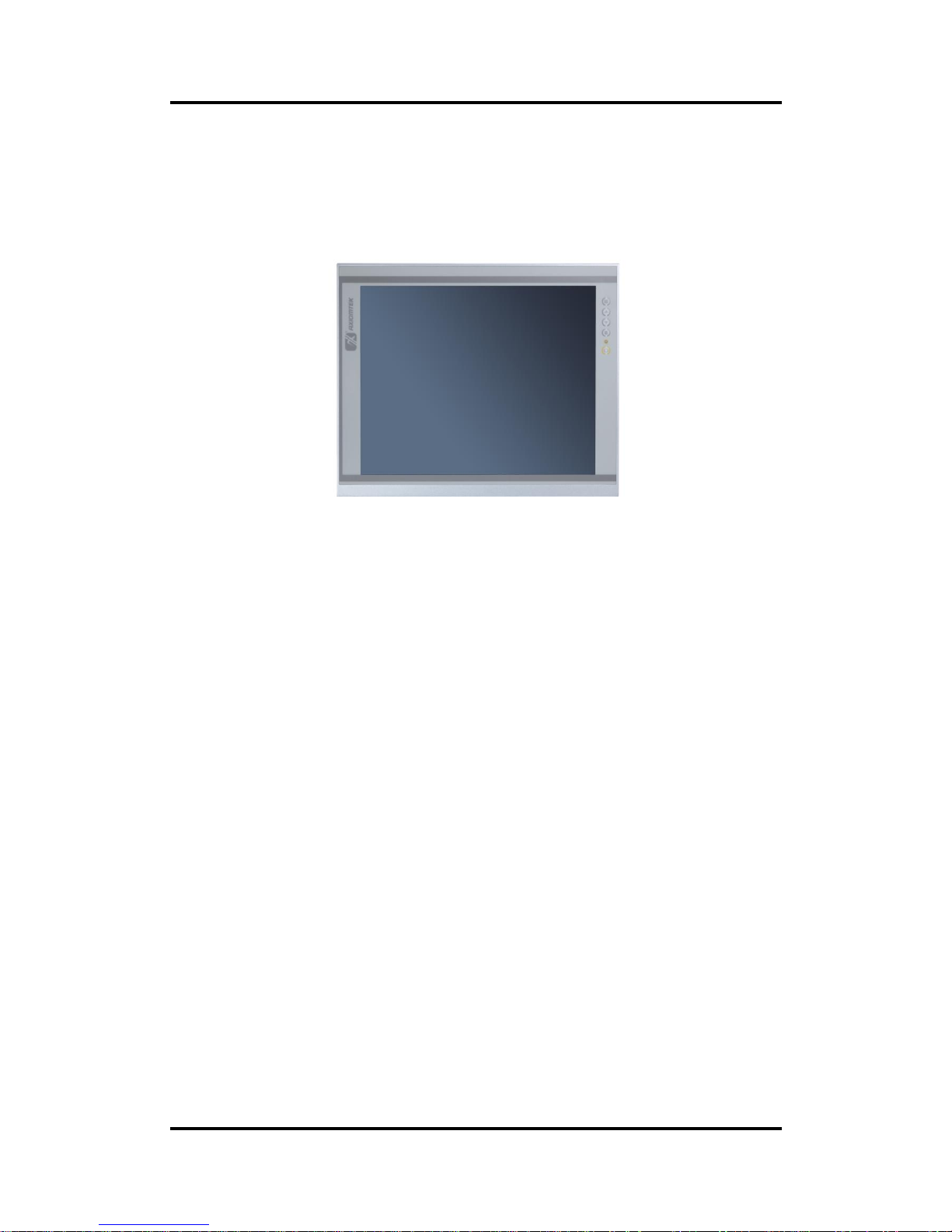
15” XGA TFT Monitor
User’s Manual
Page 2

ii
Disclaimers
This manual has been carefully checked and believed to contain accurate information.
Axiomtek Co., Ltd. assumes no responsibility for any infringements of patents or any third
party’s rights, and any liability arising from such use.
Axiomtek does not warrant or assume any legal liability or responsibility for the accuracy,
completeness or usefulness of any information in this document. Axiomtek does not make any
commitment to update the information in this manual.
Axiomtek reserves the right to change or revise this document and/or product at any time
without notice.
No part of this document may be reproduced, stored in a retrieval system, or transmitted, in
any form or by any means, electronic, mechanical, photocopying, recording, or otherwise,
without the prior written permission of Axiomtek Co., Ltd.
CAUTION
If you replace wrong batteries, it causes the danger of explosion. It is recommended by the
manufacturer that you follow the manufacturer’s instructions to only replace the same or
equivalent type of battery, and dispose of used ones.
Copyright 2016 Axiomtek Co., Ltd.
All Rights Reserved
July 2016, Version A1
Printed in Taiwan
Page 3

iii
Safety Precautions
Before getting started, read the following important cautions.
1. Be sure to ground yourself to prevent static charge when installing the internal
components. Use a grounding wrist strap and place all electronic components in any
static-shielded devices. Most electronic components are sensitive to static electrical
charge.
2. Disconnect the power cords from the P6151 Series before making any installation. Be
sure both the system and the external devices are turned OFF. Sudden surge of power
could ruin sensitive components. Make sure the P6151 Series is properly grounded.
3. Do not open the system’s top cover. If opening the cover for maintenance is a must, only
a trained technician is allowed to do so. Integrated circuits on computer boards are
sensitive to static electricity. To avoid damaging chips from electrostatic discharge,
observe the following precautions:
Before handling a board or integrated circuit, touch an unpainted portion of the
system unit chassis for a few seconds. This will help to discharge any static
electricity on your body.
When handling boards and components, wear a wrist-grounding strap, available
from most electronic component stores.
Trademarks Acknowledgments
Axiomtek is a trademark of Axiomtek Co., Ltd.
Windows® is a trademark of Microsoft Corporation.
IBM, PC/AT, PS/2, VGA are trademarks of International Business Machines Corporation.
Intel® and Pentium® are trademarks of Intel Corporation.
AMI is trademark of American Megatrend Inc.
Other brand names and trademarks are the properties and registered brands of their
respective owners.
Page 4

iv
Table of Contents
Disclaimers ..................................................................................................... ii
Safety Precautions ........................................................................................ iii
Chapter 1 Introduction ............................................. 1
1.1 General Description ............................................................................ 1
1.2 Features ............................................................................................... 2
1.3 Specifications ...................................................................................... 2
1.4 Dimensions and Outlines ................................................................... 3
1.5 I/O Outlets ............................................................................................ 4
1.6 Packing List ......................................................................................... 5
Chapter 2 System Setup .......................................... 7
2.1 System Configuration ......................................................................... 7
2.2 Panel Mounting ................................................................................... 8
2.3 Wall Mounting ...................................................................................... 8
2.4 VESA Mounting ................................................................................... 9
2.5 Rack Mounting .................................................................................. 10
Appendix A Supported Input Timing Modes ............. 11
Appendix B OSD Operation ........................................ 13
Function Description of OSD Menu ............................................................ 13
Page 5
P6151 User’s Manual
Introduction 1
Chapter 1
Introduction
This chapter contains general information and detailed specifications of the P6151. Chapter 1
includes the following sections:
General Description
Features
Specifications
Dimensions and Outlines
I/O Outlets
Package List
1.1 General Description
The P6151, an industrial 15 inches view area LCD Monitor comes with slim, light and reliable
features to replace traditional bulky CRT for Industrial application. Its unique flat design is fit for
panel mounting, VESA mounting, Wall mounting and Rack mounting. The display interface
offers DVI-D, HDMI and VGA for different input source from PC system or multimedia system
that let you upgrade the display don’t change anything from your system. Besides, for varied
HMI field, you can choose one of resistive touch or glass interface to meet your application. In
addition, this monitor has more comfort, safety, and environmental protection for humanized &
health consideration those would be the benefit that users can get.
This LCD monitor builds in color active matrix thin-film-transistor (TFT) liquid crystal display to
provide superior display performance. A maximum resolution of 1024x768 is ideal for
displaying complex graphics and high definition images. Other outstanding designs that
enhance this LCD monitor’s performance are Plug & Play compatibility, and OSD (On Screen
Display) controls, especially OSD, it made you ease adjustment on screen image.
Page 6

P6151 User’s Manual
2 Introduction
1.2 Features
High contrast color 15” XGA TFT LCD display support resolution up to 1024x768
Flat design with NEMA4/IP65-compliant
Suits with resistive touch or glass
High Brightness and Ultra-wide viewing angle with anti-glare features.
Power management system conforms to VESA DPMS standard
Advanced OSD control for picture quality adjustment
Supports VESA ARMs, Desktop Stand Rear, Panel, Wall and Rack mounting
1.3 Specifications
15” XGA(1024x768) LCD with LED backlight
Resistive Touch or glass
Front bezel design with NEMA4/IP65
Control: OSD (On Screen Display) control pad on the side
Mounting: Support Panel mount, VESA arm mount, Wall mount and Rack
mount (optional)
Net Weight
P6151P: 3.68KG
P6151O:3.12KG
Dimension (Main Body Size)
P6151O: 335X216.5X28.5 mm
P6151P: 377.9X309.3X28 mm
Operation Temperature
0℃ to 50℃
Relative Humidity
20% to 90% @ 40℃, Non-Condensing
Power input
Screw-type external AC or 12V/24VDC-in
Max power consumption: 26W
NOTE: All specifications and images are subject to change without notice.
Page 7

P6151 User’s Manual
Introduction 3
1.4 Dimensions and Outlines
The following diagrams show the dimensions and outlines of P6151
P6151P:
P6151O:
+G-
+G-
Page 8

P6151 User’s Manual
4 Introduction
1.5 I/O Outlets
Please refer to the following illustration for I/O locations of the P6151.
No
Function
No
Function
1
Menu (Enter function)
7
Screw type or
Phoenix type power input
2
SEL+
8
DisplayPort
3
SEL-
9
HDMI
4
Exit/Auto Adjust
10
DVI-D
5
Power LED
11
RS-232 or USB for Touch
6
Power Switch
1
2
3
4
5
6
Page 9

P6151 User’s Manual
Introduction 5
1.6 Packing List
When you receive the P6151, the bundled package should contain the following items:
P6151 unit x 1
VGA cable x1
USB cable or RS-232 cable x1 (for resisitve touch version only )
Adaptor x1 (for AC version only)
Panel mount kit x 10
If you can not find the package or any items are missing, please contact Axiomtek distributors
immediately.
Page 10

P6151 User’s Manual
6 Introduction
This page is intentionally left blank.
Page 11

P6151 User’s Manual
System Setup
7
Chapter 2
System Setup
This chapter details the system parts and components with figures. Sections include:
System Configuration
Panel Mounting
Wall Mounting
VESA Mounting
Rack Mounting
2.1 System Configuration
The figure below shows the side views of P6151 series.
1. Menu:
Press this button to turn on/off the OSD (On Screen Display) main menu.
Press this button to activate selected items.
2. SEL+:
To scroll up the menu.
To increase the value of selected item.
3. SEL-:
To scroll down the menu.
To decrease the value of selected item.
4. Exit:
Jump out the selection icon .
Auto adjust.
5. Power LED:
When the light is green, the power is on, red light when stand by.
6. Power switch:
Press this button to turn on/off the monitor.
1
2
3 4 5
6
Page 12

P6151 User’s Manual
8 System Setup
2.2 Panel Mounting
The P6151 is designed for panel mount application. To mount the P6151, the standard set of
mounting kit (included in the system packaging) is needed.
▲P6151 Panel Mount kits
2.3 Wall Mounting
The P6151 provides VESA mount and wall mount. Screw four screws to fix the kit in the back
chassis.
Page 13

P6151 User’s Manual
System Setup
9
2.4 VESA Mounting
The P6151 provides VESA mount at the back of system. Screw four screws to fix the kit in the
back chassis.
100mm
100mm
Page 14

P6151 User’s Manual
10 System Setup
2.5 Rack Mounting
The P6151 provides rack mount at the back of system. Screw eight screws to fix the kit in the
back chassis.
Page 15

P6151 User’s Manual
Supported Input Timing Modes
11
Appendix A
Supported Input Timing Modes
Supported Input Timing Modes
SPEC
MODE
Pixel
Freq.
Horizontal Timing
Vertical Timing
Sync
Polar
Freq.
Total
Active
Sync
Polar
Freq.
Total
Active
MHZ
KHz
Pixel
Pixel
Hz
Line
Line
640×350
@70Hz
24.144
VESA
P
31.430
800
640 N 70.000
449
350
640×480
@60Hz
25.175
VESA
N
31.469
800
640 N 59.940
525
480
640×480
@60Hz
25.175
VESA
N
31.469
800
640 N 59.940
525
480
640×480
@72Hz
31.500
VESA
N
37.861
832
640 N 72.809
520
480
640×480
@75Hz
31.500
VESA
N
37.500
840
640 N 75.000
500
480
720×400
@70Hz
28.287
VESA
N
31.430
900
720 P 70.000
449
400
800×600
@56Hz
36.000
VESA
P
35.156
1024
800 P 56.250
625
600
800×600
@60Hz 0
40.000
VESA
P
37.879
1056
800 P 60.317
628
600
800×600
@72Hz
50.000
VESA
P
48.077
1040
800 P 72.188
666
600
800×600
@75Hz
49.500
VESA
P
46.875
1056
800 P 75.000
625
600
Page 16

P6151 User’s Manual
12 Supported Input Timing Modes
SPEC
MODE
Pixel
Freq.
Horizontal Timing
Vertical Timing
Sync
Polar
Freq.
Total
Active
Sync
Polar
Freq.
Total
Active
MHZ
KHz
Pixel
Pixel
Hz
Line
Line
1024×768
@60Hz
65.000
VESA
N
48.363
1344
1024
N
60.005
806
768
1024×768
@60Hz
64.000
VESA
N
48.780
1312
1024
N
60.001
813
768
1024×768
@70Hz
75.000
VESA
N
56.476
1328
1024
N
70.070
806
768
1024×768
@75Hz
80.000
VESA
N
60.241
1328
1024
N
74.927
804
768
1024×768
@75Hz
78.750
VESA
P
60.023
1312
1024
P
75.030
800
768
NOTE: Timing depends on LCD Panel’s requirement.
Page 17

P6151 User’s Manual
OSD Operation 13
Appendix B
OSD Operation
Function Description of OSD Menu
※The layout and format of OSD depends on customer’s request.
OSD MENU
Description
Luminance
Luminance:
Brightness
Contrast
Sharpness
Pciture
Picture
Phase
Clock
H position
V position
Color
Color:
Color Temperature (6500,7500,9300,user define)
Red
Green
Blue.
OSD
OSD Settings:
Horizontal
Vertical
Transparency
OSD Time out .
Setup
Setup:
Language
Volume
Mute
Input
Reset
This page is intentionally left blank.
 Loading...