

Page 1

P6105
10.4” XGA TFT Railway Monitor
User’s Manual
Page 2

ii
Disclaimers
This manual has been carefully checked and believed to contain accurate information.
Axiomtek Co., Ltd. assumes no responsibility for any infringements of patents or any third
party’s rights, and any liability arising from such use.
Axiomtek does not warrant or assume any legal liability or responsibility for the accuracy,
completeness or usefulness of any information in this document. Axiomtek does not make any
commitment to update the information in this manual.
Axiomtek reserves the right to change or revise this document and/or product at any time
without notice.
No part of this document may be reproduced, stored in a retrieval system, or transmitted, in
any form or by any means, electronic, mechanical, photocopying, recording, or otherwise,
without the prior written permission of Axiomtek Co., Ltd.
Copyright 2018 Axiomtek Co., Ltd.
All Rights Reserved
June 2018, Version A3
Printed in Taiwan
Page 3

iii
Safety Precautions
Before getting started, read the following important cautions.
1. Be sure to ground yourself to prevent static charge when installing the internal
components. Use a grounding wrist strap and place all electronic components in any
static-shielded devices. Most electronic components are sensitive to static electrical
charge.
2. Disconnect the power cords from the P6105 Series before making any installation. Be
sure both the system and the external devices are turned OFF. Sudden surge of power
could ruin sensitive components. Make sure the P6105 Series is properly grounded.
3. Do not open the system’s top cover. If opening the cover for maintenance is a must, only
a trained technician is allowed to do so. Integrated circuits on computer boards are
sensitive to static electricity. To avoid damaging chips from electrostatic discharge,
observe the following precautions:
Before handling a board or integrated circuit, touch an unpainted portion of the
system unit chassis for a few seconds. This will help to discharge any static
electricity on your body.
When handling boards and components, wear a wrist-grounding strap, available
from most electronic component stores.
Trademarks Acknowledgments
Axiomtek is a trademark of Axiomtek Co., Ltd.
IBM, PC/AT, PS/2, VGA are trademarks of International Business Machines Corporation.
AMI is trademark of American Megatrend Inc.
Other brand names and trademarks are the properties and registered brands of their
respective owners.
Page 4

iv
Table of Contents
Disclaimers ...................................................................................................... i
Safety Precautions ........................................................................................ iii
Chapter 1 Introduction .............................................. 1
1.1 General Description ............................................................................ 1
1.2 Features ............................................................................................... 2
1.3 Specifications ...................................................................................... 2
1.4 Dimensions and Outlines ................................................................... 3
1.5 I/O Outlets ............................................................................................ 4
1.6 Packing List ......................................................................................... 5
Chapter 2 System Setup ............................................ 7
2.1 System Configuration ......................................................................... 8
2.2 Panel Mounting.................................................................................... 9
2.3 VESA Mounting ................................................................................... 9
2.4 I/O PIN ASSIGNMENT ........................................................................ 10
2.4.1 DC power Jack w/ M12 connector, 24VDC or 110VDC power input ......... 10
2.4.2 Waterproof Power Cable ........................................................................ 10
2.4.3 VGA PORT............................................................................................. 11
2.4.4 RS 232 PORT, support multi-function of T/S and remote. ........................ 11
2.4.5 Y cable for RS-232 to resistive touch and remote ................................... 12
2.4.6 HDMI PORT ........................................................................................... 13
2.4.7 DVI-D PORT .......................................................................................... 13
Appendix A Supported Input Timing Modes .............. 15
Appendix B OSD Operation ......................................... 17
Function Description of OSD Menu ............................................................ 17
Appendix C AD Board Management System .............. 19
Page 5
P6105 User’s Manual
Introduction 1
Chapter 1
Introduction
This chapter contains general information and detailed specifications of the P6105. Chapter 1
includes the following sections:
General Description
Features
Specifications
Dimensions and Outlines
I/O Outlets
Package List
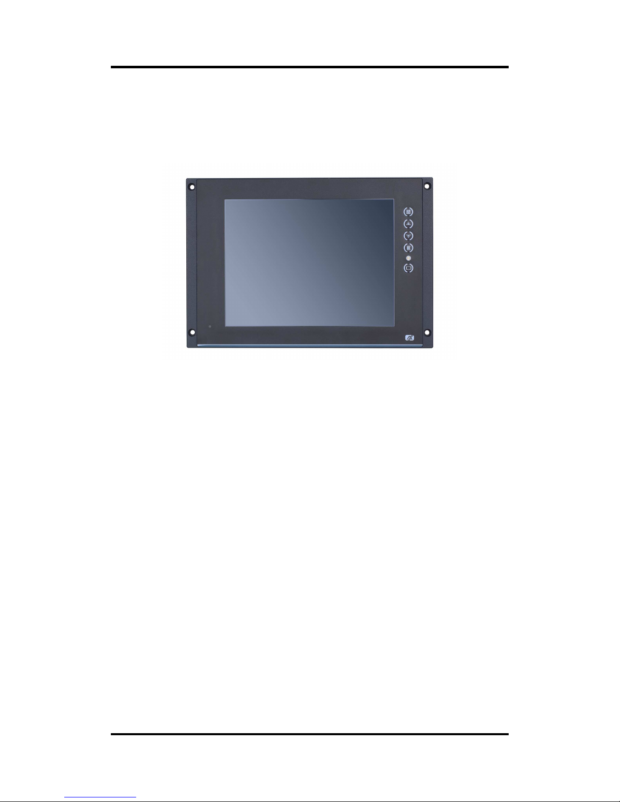
1.1 General Description
The P6105, a industrial 10.4 inches view area LCD Monitor comes with slim, light and reliable
features to replace traditional bulky CRT for Industrial application. Its unique flat design is fit for
panel mounting and VESA mounting. The display interface offers DVI-D, HDMI digital
interfaces and VGA for different input source from PC system or multimedia system that let you
upgrade the display don’t change anything from your system. With a anti-vibration design, the
rugged HMI can work well on the train.
This LCD monitor builds in color active matrix thin-film-transistor (TFT) liquid crystal display to
provide superior display performance. A maximum resolution of 1024x768 is ideal for
displaying complex graphics and high definition images. Other outstanding designs that
enhance this LCD monitor’s performance are Plug & Play compatibility, and OSD (On Screen
Display) controls, especially OSD, it made you ease adjustment on screen image.
Page 6

P6105 User’s Manual
2 Introduction
1.2 Features
High contrast color 10.4” XGA TFT LCD display support resolution up to 1024x768
Auto-dimming for different environment
Flat design with NEMA4/IP65-compliant
Suits with resistive touch
High Brightness and Ultra-wide viewing angle with anti-glare features.
Power management system conforms to VESA standard
Advanced OSD control for picture quality adjustment
Provide remote control for OSD adjustment (refer to Appendix C)
1.3 Specifications
10” XGA(1024x768) LCD with LED backlight
Resistive To uch
Front bezel design with NEMA4/IP65
Control: OSD (On Screen Display) control pad on the side
Moun ting: Suppo rt Panel mount and VESA arm mount
Net Weight
P6105: 2KGS
Dimension (Main Body Size)
P6105: 310X214X49.2 mm
Operation Temperature
-25
to 55
Relative Humidity
20% to 90% @ 40
, Non-Condensing
Power input
24VDC or 110VDC power input
Max power consumption: 15.6W
Audio
3W speaker x 1
Line-In for audio input from VGA / DVI-D
NOTE: All specifications and images are subject to change without notice.
Page 7
P6105 User’s Manual
Introduction 3
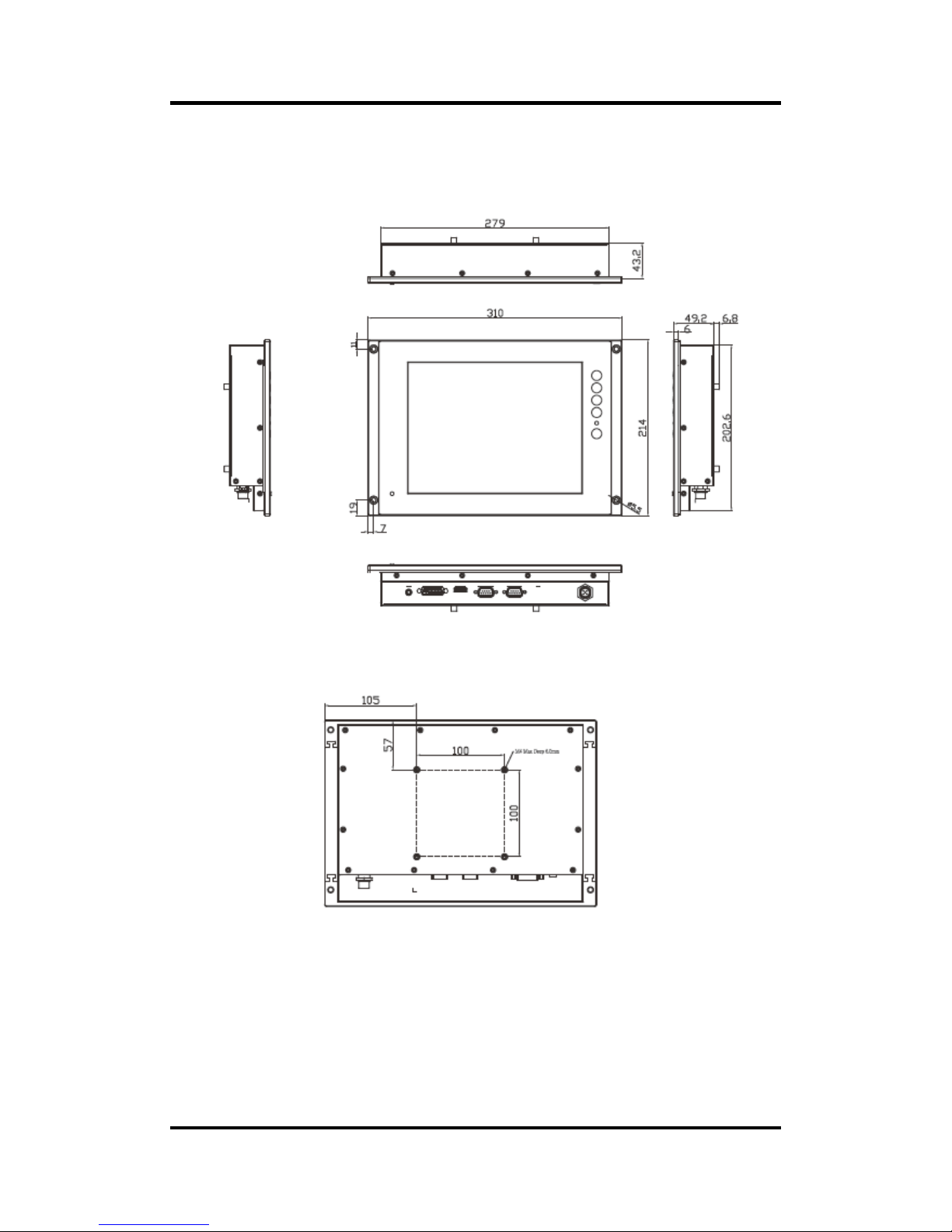
1.4 Dimensions and Outlines
The following diagrams show the dimensions and outlines of P6105
Page 8
P6105 User’s Manual
4 Introduction
1.5 I/O Outlets
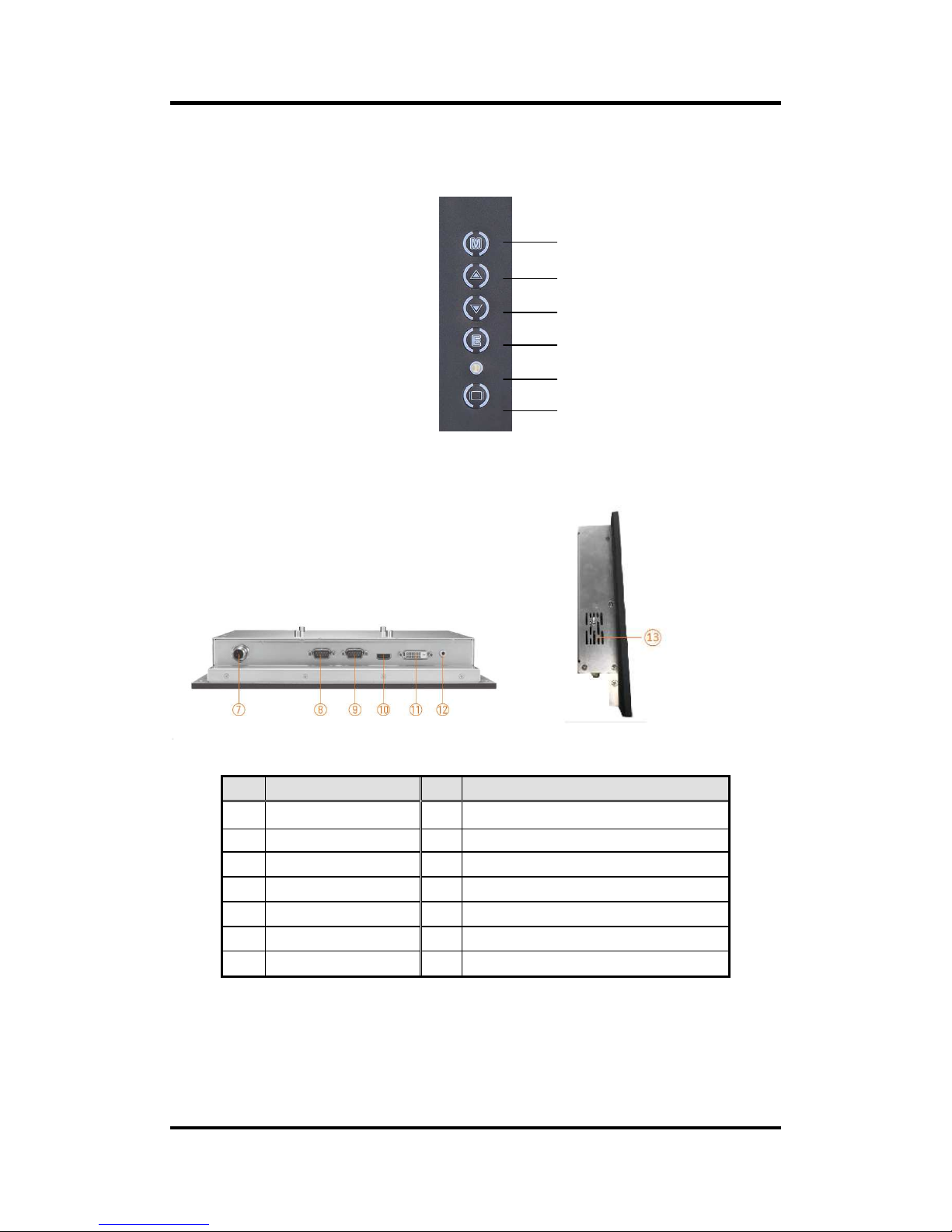
Please refer to the following illustration for I/O locations of the P6105.
I/O outlets with VGA input and speaker
No Function No Function
1 Menu (Enter function) 8 Touch & remote control via RS-232
2 SEL+ 9 VGA
3 SEL- 10 HDMI
4 Exit 11 DVI-D
5 Power LED 12 Line-in
6 Power Switch 13 Speaker
7 DC power input
1
2
3
4
5
6
Page 9

P6105 User’s Manual
Introduction 5
1.6 Packing List
When you receive the P6105 VGA input version, the bundled package should contain the
following items:
P6105 unit x 1
VGA cable x 1
RS-232 cable x1 (for resisitve touch)
If you request for a cable assembly for resistive touch and remote control, please refer to
section 2.4: Pin assignment.
If you cannot find the package or any items are missing, please contact Axiomtek distributors
immediately.
Page 10

P6105 User’s Manual
6 Introduction
This page is intentionally left blank.
Page 11

P6105 User’s Manual
System Setup
7
Chapter 2
System Setup
This chapter details the system parts and components with figures. Sections include:
System Configuration
Panel Mounting
VESA Mounting
I/O Pin Assignment
DC Power
Waterproof Power Cable
VGA PORT
RS-232 PORT, support multi-function of T/S and remote
Y cable for RS-232 to resistive touch and remote
HDMI PORT
DVI-D PORT
Page 12

P6105 User’s Manual
8 System Setup
2.1 System Configuration
The figure below shows the side views of P6105 series.
1. Menu:
Press this button to turn on/off the OSD (On Screen Display) main menu.
Press this button to activate selected items.
2. SEL+:
To scroll up the menu.
To increase the value of selected item.
3. SEL-:
To scroll down the menu.
To decrease the value of selected item.
4. Exit:
Jump out the selection icon .
Auto adjust.
5. Power LED:
When the light is green, the power is on, red light when stand by.
6. Power switch:
Press this button to turn on/off the monitor.
Page 13

P6105 User’s Manual
System Setup
9
2.2 Panel Mounting
The P6105 is designed for panel mount application. To mount the P6105, the standard holes
are on the front of P6105.
2.3 VESA Mounting
The P6105 provides rack mount at the back of system. Screw four screws to fix the kit in the
back chassis.
Page 14

P6105 User’s Manual
10 System Setup
2.4 I/O PIN ASSIGNMENT
The P6105 supports DC-in connector, T/S port, HDMI port, DVI-D port, and Line-In port. Detail
pin assignment, please refer to following information.
2.4.1 DC power Jack w/ M12 connector, 24VDC or 110VDC power
input
2.4.2 Waterproof Power Cable
Please follow the pin assignment for the power input.
Pin
Signal
V+
DC +24V power input
Earth Ground
GND
GND
GND GND
Pin Signal
1 V+ (+24V)
2 V+ (+24V)
3 GND
4 GND
5 Earth Gound
Page 15

P6105 User’s Manual
System Setup 11
2.4.3 VGA PORT
Pin Define Pin Define Pin Define
1 Red 6 Red GND 11 N.C.
2 Green 7 Green GND 12 DDC Data
3 Blue 8 Blue GND 13 H-Sync
4 N.C. 9 +5V (In) 14 V-Sync
5 Ground 10 Ground 15 DDC Clock
2.4.4 RS 232 PORT, support multi-function of T/S and remote.
Pin Define Pin Define
1 Remote RXD 6 Touch DTR
2 Touch TXD 7 Touch RTS
3 Touch RXD 8 Remote TXD
4 Touch DSR 9 N.C.
5 Ground
Page 16

P6105 User’s Manual
12 System Setup
2.4.5 Y cable for RS-232 to resistive touch and remote
DB9 – Connect to P6105
DB9 male, connect to P6105
Pin Define Pin Define
1 Remote RXD 6 Touch DTR
2 Touch TXD 7 Touch RTS
3 Touch RXD 8 Remote TXD
4 Touch DSR 9 N.C.
5 Ground
DB9 female, connect to PC for touch
Pin Define Pin Define
1 N.C. 6 Touch DTR
2 Touch TXD 7 Touch RTS
3 Touch RXD 8 N.C.
4 Touch DSR 9 N.C.
5 Ground
DB9 female, connect to PC for remote
Pin Define Pin Define
1 N.C. 6 N.C.
2 Remote RXD 7 N.C.
3 Remote TXD 8 N.C.
4 N.C. 9 N.C.
5 Ground
Page 17

P6105 User’s Manual
System Setup 13
2.4.6 HDMI PORT
Pin Define Pin Define Pin Define
1 TMDS2+ 8 GND 15 DDC clock
2
Cable Detect
(GND) 9 TMDS0- 16 DDC Date
3 TMDS2- 10 TMDS clock+ 17 GND
4 TMDS1+ 11 GND 18 Vin (+5V)
5 GND 12 TMDS clock- 19 Hot plug detect
6 TMDS1- 13 N.C.
7 TMDS0+ 14 N.C.
2.4.7 DVI-D PORT
Pin Define Pin Define Pin Define Pin Define
1 TMDS2− 7 DDC data 13 N.C. 19 GND
2 TMDS2+ 8 N.C. 14 Vin (+5V) 20 N.C.
3 GND 9 TMDS1- 15 GND 21 N.C.
4 N.C. 10 TMDS1+ 16 Hot plug detect 22 GND
5 N.C. 11 GND 17 TMDS0- 23 TMDS clock+
6 DDC clock 12 N.C. 18 TMDS0+ 24 TMDS clock−
Page 18

P6105 User’s Manual
14 System Setup
This page is intentionally left blank.
Page 19

P6105 User’s Manual
Supported Input Timing Modes 15
Appendix A
Supported Input Timing Modes
SPEC
MODE
Pixel
Freq.
Horizontal Timing Vertical Timing
Sync
Polar
Freq. Total Active
Sync
Polar
Freq. Total Active
MHZ KHz Pixel Pixel Hz Line Line
640×480
@60Hz
25.175
VESA
N 31.469 800 640 N 59.940 525 480
640×480
@60Hz
25.175
VESA
N 31.469 800 640 N 59.940 525 480
800×600
@60Hz 0
40.000
VESA
P 37.879 1056 800 P 60.317 628 600
SPEC
MODE
Pixel
Freq.
Horizontal Timing Vertical Timing
Sync
Polar
Freq. Total Active
Sync
Polar
Freq. Total Active
MHZ KHz Pixel Pixel
Hz Line Line
1024×768
@60Hz
65.000
VESA
N 48.363 1344 1024 N 60.005 806 768
NOTE: Timing depends on LCD Panel’s requirement.
Page 20

P6105 User’s Manual
16 Supported Input Timing Modes
This page is intentionally left blank.
Page 21

P6105 User’s Manual
OSD Operation 17
Appendix B
OSD Operation
Function Description of OSD Menu
The layout and format of OSD depends on customer’s request.
c Description
Luminance
Luminance
Brightness
Contrast
Sharpness
Ambient Sense
Color
Color:
Color Temperature (9300,7500,6500,user)
Red
Green
Blue
OSD
OSD Settings
Horizontal
Vertical
Transparency
OSD Time out
Setup
Setup:
Language
Input
Reset
Touch On/Off
Page 22

P6105 User’s Manual
18 OSD Operation
This page is intentionally left blank.
Page 23

P6105 User’s Manual
AD Board Management System 19
Appendix C
AD Board Management System
Digital Signage System Control Tool
File:
1. ADS_Client.exe: main application
2. ADS_RS-232_x32.dll / ADS_RS-232_x64.dll: library for application reference,
have to copy to System_Disk(C:):\Windows\System32 or with ADS_Client.exe
UI
Digital Signage System Control Tool is for controlling 10 items of AD Board through
serial port (RS-232). The items are:
1. Brightness scale get and set
2. Contrast scale get and set
3. Backlight MAX scale get and set (works when Auto-Dimming is on)
4. Backlight MIN scale get and set (works when Auto-Dimming is on)
5. Color Temperature scale get and set
6. PIR on/off and timer get and set
7. Power on/off set for monitor
8. Video status get
9. Auto-Dimming on/off and timer get and set
10. Adjust position of frame on monitor (only works with monitor connecting on
VGA port)
Page 24

P6105 User’s Manual
20 AD Board Management System
Functions and UI on application
When application is executed, it will auto scan all serial port to find out correctly port
you connect AD Board on.
If application couldn’t find out serial port to connect to AD Board, you need select
port number and Baud Rate to setup connection.
Page 25

P6105 User’s Manual
AD Board Management System 21
Control Items
1. Brightness
Control: scroll bar
Range: 0 ~ 100
Remark: if getting or setting is failed, it will show “Brightness - Failed”
2. Contrast
Control: scroll bar
Range: 0 ~ 100
Remark: if getting or setting is failed, it will show “Contrast - Failed”
3. Backlight MAX:
Control: drop-down list
Range: 0 ~ 100
Remark: this value can’t smaller than value of Backlight MIN
Remark: if getting or setting is failed, it will show “Backlight MAX - Failed”
Page 26

P6105 User’s Manual
22 AD Board Management System
4. Backlight MIN:
Control: drop-down list
Range: 0 ~ 100
Remark: this value can’t bigger than value of Backlight MAX
Remark: if getting or setting is failed, it will show “Backlight MIN - Failed”
5. Color Temp.:
Control: drop-down list
Range: 6500, 7500 and 9300
Remark: if getting or setting is failed, it will show “Color Temp. - Failed”
6. PIR: (Option)
Control: drop-down list
Range: OFF, 5min., 10min., 20min. and 30min.
Remark: if getting or setting is failed, it will show “PIR - Failed”
Remark: if there is no PIR, it will show “PIR - Disable”
7. Power:
Control: button
Way: set only, ON and OFF
Remark: if setting is failed, it will show “Power - Failed”
8. Video: (Option)
Control: button
Way: get only, Normal and No Good
Remark: if setting is failed, it will show “Video - Failed”
Remark: if there is no Video Detect, it will show “Video - Disable”
Page 27

P6105 User’s Manual
AD Board Management System 23
9. Dim: (Option)
Control: button
Way: ON and OFF
Remark: if setting is failed, it will show “Auto-Dimming - Failed”
Remark: if there is no Auto-Dimming, it will show “Auto-Dimming -
Disable”
10. Adjust:
Control: button
Way: set only, Adjust
Remark: if setting is failed, it will show “Adjust - Failed”
11. Rescanning all Status
Control: button
Remark: getting all status
12. Input Source
Control: Text box
Remark: showing which one is input source (DVI/VGA/HDMI/DP)
Page 28

P6105 User’s Manual
24 AD Board Management System
This page is intentionally left blank.
 Loading...