

Page 1

P1177E-842
All-in-One
17” SXGA TFT Expandable
PANEL PC
User’s Manual
Page 2

ii
Disclaimers
This manual has been carefully checked and believed to contain accurate information.
Axiomtek Co., Ltd. assumes no responsibility for any infringements of patents or any third
party’s rights, and any liability arising from such use.
Axiomtek does not warrant or assume any legal liability or responsibility for the accuracy,
completeness or usefulness of any information in this document. Axiomtek does not make any
commitment to update the information in this manual.
Axiomtek reserves the right to change or revise this document and/or product at any time
without notice.
No part of this document may be reproduced, stored in a retrieval system, or transmitted, in
any form or by any means, electronic, mechanical, photocopying, recording, or otherwise,
without the prior written permission of Axiomtek Co., Ltd.
CAUTION
If you replace wrong batteries, it causes the danger of explosion. It is recommended by the
manufacturer that you follow the manufacturer’s instructions to only replace the same or
equivalent type of battery, and dispose of used ones.
Copyright 2015 Axiomtek Co., Ltd.
All Rights Reserved
November 2015, Version A1
Printed in Taiwan
Page 3

iii
Safety Precautions
Before getting started, read the following important cautions.
1. Be sure to ground yourself to prevent static charge when installing the internal
components. Use a grounding wrist strap and place all electronic components in any
static-shielded devices. Most electronic components are sensitive to static electrical
charge.
2. Disconnect the power cords from the P1000 Series before making any installation. Be
sure both the system and the external devices are turned OFF. Sudden surge of power
could ruin sensitive components. Make sure the P1000 Series is properly grounded.
3. Do not open the system’s top cover. If opening the cover for maintenance is a must, only
a trained technician is allowed to do so. Integrated circuits on computer boards are
sensitive to static electricity. To avoid damaging chips from electrostatic discharge,
observe the following precautions:
Before handling a board or integrated circuit, touch an unpainted portion of the
system unit chassis for a few seconds. This will help to discharge any static
electricity on your body.
When handling boards and components, wear a wrist-grounding strap, available
from most electronic component stores.
Trademarks Acknowledgments
Axiomtek is a trademark of Axiomtek Co., Ltd.
Windows® is a trademark of Microsoft Corporation.
IBM, PC/AT, PS/2, VGA are trademarks of International Business Machines Corporation.
Intel® and Pentium® are trademarks of Intel Corporation.
AMI is trademark of American Megatrend Inc.
Other brand names and trademarks are the properties and registered brands of their
respective owners.
Page 4

iv
Table of Contents
Disclaimers ..................................................................................................... ii
Safety Precautions ........................................................................................ iii
Chapter 1 Introduction ............................................. 1
1.1 General Description ............................................................................ 1
1.2 Specifications ...................................................................................... 2
1.3 Dimensions and Outlines ................................................................... 4
1.4 I/O Outlets ............................................................................................ 6
1.5 Packing List ......................................................................................... 7
Chapter 2 Hardware and Installation ...................... 9
2.1 Open back cover ............................................................................... 10
2.2 Serial Ports Interface ........................................................................ 11
2.3 Ethernet .............................................................................................. 11
2.4 Mountings: Panel / Wall / Rack / Desktop / VESA ........................... 12
2.4.1 VESA-ARM / Wall-Mount / Desktop-mount ............................................... 12
2.4.2 Panel-mount Kit Assembly ........................................................................ 13
2.4.3 Rack-mount Kit Assembly ......................................................................... 14
2.5 HDD Installation ................................................................................. 15
2.6 DRAM Installation .............................................................................. 17
2.7 Wireless LAN Module Installation (optional) ................................... 19
2.8 Add-on Card Installation ................................................................... 21
2.9 Board Layout ..................................................................................... 23
2.10 Rear I/O .............................................................................................. 24
2.11 Jumper Settings ................................................................................ 25
2.11.1 Clear CMOS Select (JP1) ......................................................................... 26
2.11.2 LVDS VDD Select (JP2) ............................................................................ 26
2.11.3 AT/ATX Power Mode Select (JP4) ............................................................ 26
2.11.4 COM1 RS-232/422/485 Mode Select (JP5, JP6, JP7) ............................. 27
2.11.5 COM2 RS-232/422/485 Mode Select (JP8, JP9, JP10) ........................... 27
2.11.6 COM3 Data/Power Select (JP11) .............................................................. 27
Chapter 3 AMI BIOS Setup Utility .......................... 29
3.1 Starting ............................................................................................... 29
3.2 Navigation Keys ................................................................................ 29
3.3 Main Menu .......................................................................................... 30
Page 5

v
3.4 Advanced Menu ................................................................................. 31
3.5 Chipset Menu ..................................................................................... 45
3.6 Security Menu .................................................................................... 51
3.7 Boot Menu .......................................................................................... 52
3.8 Save & Exit Menu .............................................................................. 53
Chapter 4 Drivers Installation .............................. 55
4.1 System ............................................................................................... 55
4.2 Touch Screen ..................................................................................... 55
4.3 Embedded O.S. .................................................................................. 59
Page 6

vi
This page is intentionally left blank.
Page 7
P1177E-842 User’s Manual
Introduction 1
Chapter 1
Introduction
This chapter contains general information and detailed specifications of the P1177E-842.
Chapter 1 includes the following sections:
General Description
Specification
Dimensions
I/O Outlets
Package List
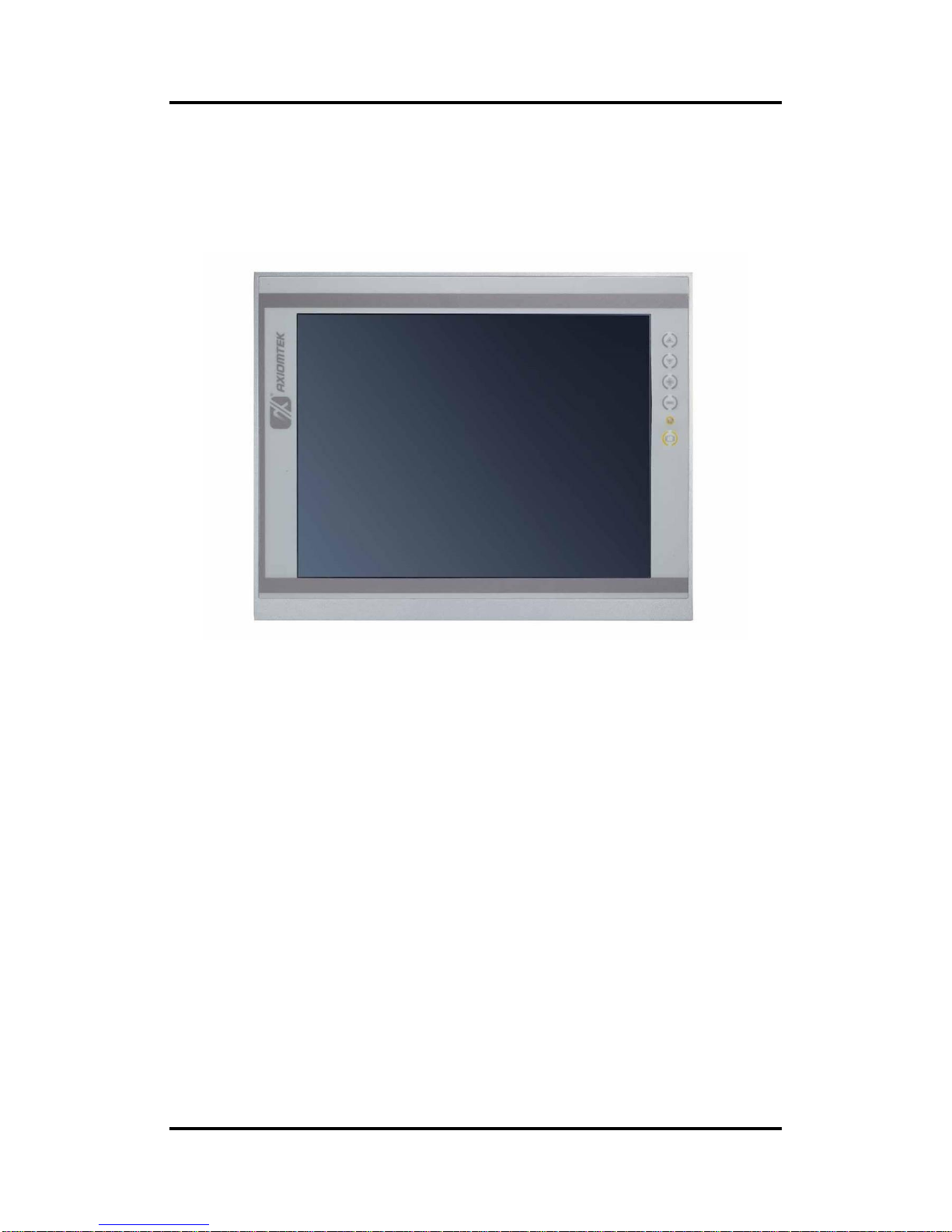
1.1 General Description
The P1177E-842 adopts a 17-inch SXGA TFT LCD with 250-nits brightness and Intel®
Celeron® Processor J1900 at 2.0 GHz to provide excellent computing performance with low
power consumption. Furthermore, P1177E-842 adopts built-in speaker and option WLAN
module for wireless connectivity.
Industrial-grade front bezel
P1177E-842 adopts industrial-grade material front bezel which incorporates the advantages of
light weight, high degree of hardness better heat releasing, easy-to-shape and anti-corrosion
ability. Therefore, P1177E-842 is especially suitable for most rugged industrial environments.
Expandable for PCIe (PCI optional)
P1177E-842 has 1 PCIe (1 PCI optional) for expansion purpose. User can easily plug in
standard half-size PCI or PCIe card for any requirement.
Page 8

P1177E-842 User’s Manual
2 Introduction
Speaker and WLAN Antenna Supported
P1177E-842 features built-in speakers for kiosk application to display multimedia content
program. It also supports WLAN module (optional) antenna for wireless network connectivity.
Low power consumption computing: Intel® Celeron® Processor J1900
P1177E-842 is powered by Intel® Celeron® Processor J1900 at 2.0 GHz which deliver great
balance between computing performance and low power consumption. Intel® Bay Trail SoC
offers reliable and stable performance and rugged environment.
1.2 Specifications
Main CPU Board
CPU
Intel® Celeron® Processor J1900 at 2.0 GHz
System Chipset
Intel® Bay Trail SoC
System Memory
1 x 204-pin DDR3L 1600/1333 MHz SO-DIMM socket
Maximum up to 8GB DDR3L memory.
BIOS
AMI BIOS via SPI interface with socket
I/O System
Standard I/O
2 x RS-232/422/485, 2 x RS-232
3 x USB 2.0
1 x USB 3.0
1 x HDMI
1 x VGA
Ethernet
2 x RJ45 GbE LAN Ports, Support 1000/100/10Mbps Gigabit/Fast Ethernet.
Audio
1 x Line-out
1 x Mic-in
Expansion
1 x PC x1 slot.
1 x PCI-Express Mini Card; only support WIFI and 3G.
1 x SIM card slot.
Storage
1 x 2.5” or 3.5” SATA HDD
Power connector
1 x AC plug
Page 9

P1177E-842 User’s Manual
Introduction 3
System Specification
17” SXGA (1280x1024) LCD
5 wired resistive Touch
IP65/NEMA4 aluminum front bezel
Net Weight
6.3 Kgs (13.89 lb)
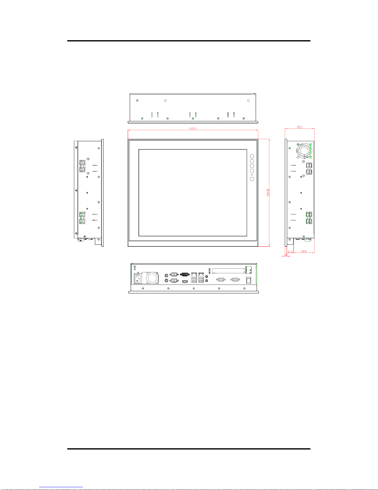
Dimension (Main Body Size)
410 mm (16.14”) (W) x 92 mm (3.62”) (D) x 338mm (13.30”) (H)
Operation Temperature
0°C to 45°C
Relative Humidity
10% to 90% @ 40°C, Non-Condensing
Power Input
100~240VAC power connector
NOTE 1. All specifications and images are subject to change without notice.
2. Long press the button of OSD doesn’t have “repeat” function.
Page 10
P1177E-842 User’s Manual
4 Introduction
1.3 Dimensions and Outlines
The following diagrams show the dimensions and outlines of P1177E-842.
Page 11

P1177E-842 User’s Manual
Introduction 5
Page 12
P1177E-842 User’s Manual
6 Introduction
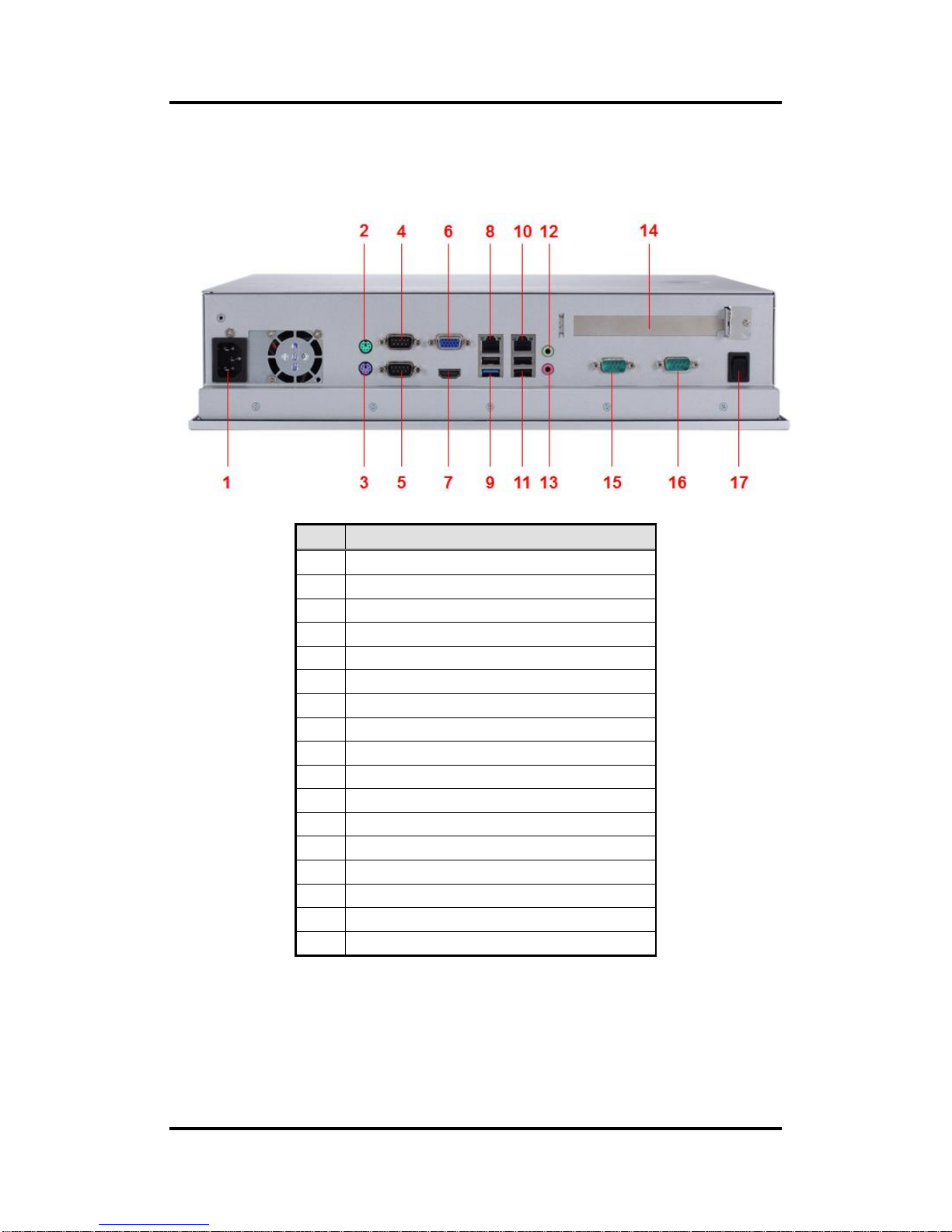
1.4 I/O Outlets
Please refer to the following illustration for I/O locations of the P1177E-842.
No
Function
1
1 x AC Plug
2
PS/2 Mouse
3
PS/2 Keyboard
4
1 x RS-232/422/485 (COM1)
5
1 x RS-232/422/485 (COM2)
6
1 x VGA
7
1 x HDMI
8
1 x RJ45 for GIGA Ethernet
9
1 x USB3.0, 1 x USB2.0
10
1 x RJ45 for GIGA Ethernet
11
2 x USB2.0
12
1 x Line-out
13
1 x Mic-in
14
1 x PCI Card expansion slot
15
1 x RS-232 (COM3)
16
1 x RS-232 (COM4)
17
1 x Switch for power on/off
Page 13

P1177E-842 User’s Manual
Introduction 7
1.5 Packing List
When you receive the P1177E-842, the bundled package should contain the following items:
P1177E-842 unit x 1
Driver CD x 1
Panel mount kit x 7
Wall/VESA mount kit x 1 (optional)
Rack mount kit x 1 (optional)
Power cord x 1
If you can not find the package or any items are missing, please contact Axiomtek distributors
immediately.
Page 14

P1177E-842 User’s Manual
8 Introduction
This page is intentionally left blank.
Page 15

P1177E-842 User’s Manual
Hardware and Installation 9
Chapter 2
Hardware and Installation
The P1177E-842 provides rich I/O ports and flexible expansions for you to meet different
demand. The chapter will show you how to install the hardware. It includes:
Open Back Cover
Serial Port Interface
Ethernet
Mounting Method
HDD Installation
DRAM Installation
Wireless LAN Module (optional)
Add-On Card Installation
Jumper Settings
Page 16
P1177E-842 User’s Manual
10 Hardware and Installation
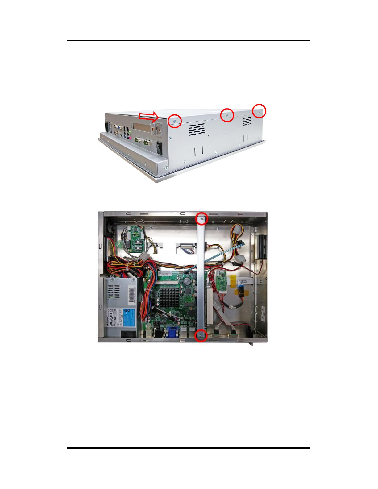
2.1 Open back cover
This section tells users how to open back cover. Please follow the steps below.
Step 1 Unscrew 3 screws on the back cover and push to the right side. Please refer
the photo below.
Step 2 Remove the back cover and unscrew 2 screws.
Page 17
P1177E-842 User’s Manual
Hardware and Installation 11
2.2 Serial Ports Interface
This motherboard supports RS-232/422/485 on COM1 & COM2 ports; 2 x RS-232 on COM3 &
COM4. The pin assignments are listed in table below. If you need to adjust these COM ports to
work as RS-232/422/485, please refer to BIOS setting in section 3.4.
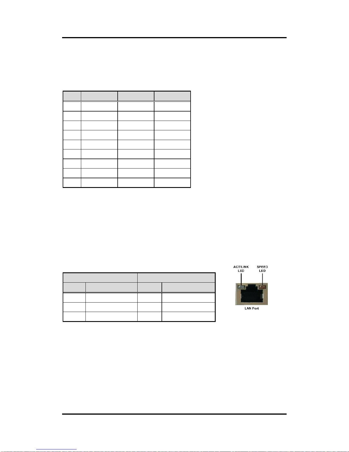
2.3 Ethernet
The P1177E-842 is equipped with two high performance plug and play Ethernet interfaces
(RJ-45) which are fully compliant with the IEEE 802.3 standard. Connection can be
established by plugging one end of the Ethernet cable into this RJ-45 connector and the other
end to a 1000/100/10-Base-T hub.
There are two LEDs next to the LAN port. Please refer to the table below for the LAN port LED
indications.
LAN Port LED Indications
Pin
RS-232
RS-422
RS-485
1
DCD#
TX-
485- 2 RXD
TX+
485+
3
TXD
RX+
N/C 4 DTR#
RX-
N/C 5 GND
GND
GND
6
DSR#
N/C
N/C 7 RTS#
N/C
N/C 8 CTS#
N/C
N/C
9
RI#
N/C
N/C
Activity/Link LED
SPEED LED
Status
Description
Status
Description
OFF
No link
OFF
10Mbps connection
Blinking
Data activity
Green
100Mbps connection
ON
Link
Orange
1Gbps connection
Page 18
P1177E-842 User’s Manual
12 Hardware and Installation
2.4 Mountings: Panel / Wall / Rack / Desktop / VESA
There are 5 application options for the P1177E-842, including Panel/Wall/Rack/ Desktop/VESA
mounting ways.
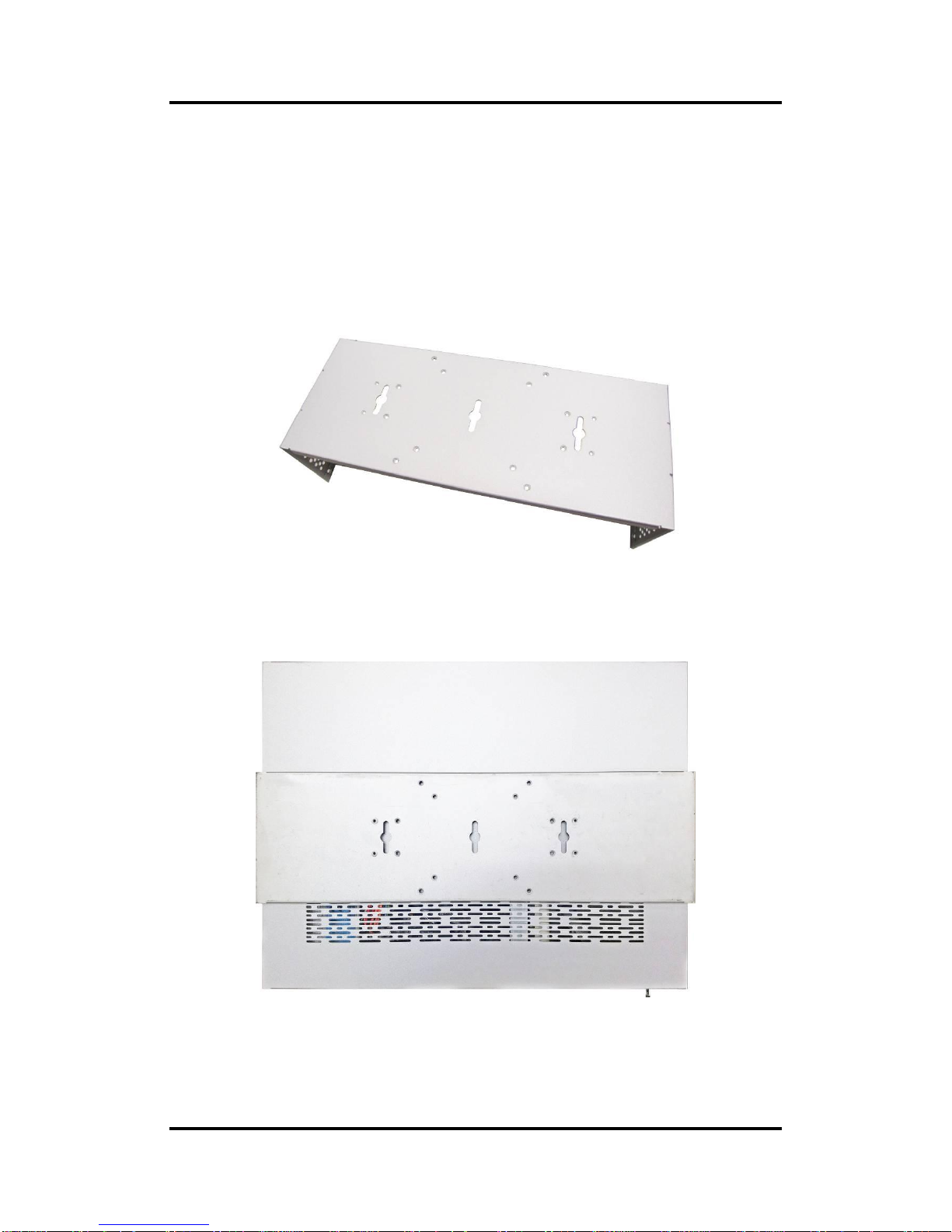
2.4.1 VESA-ARM / Wall-Mount / Desktop-mount
The P1177E-842 provides VESA mount: 75x75 mm or 100x100mm. Screw six screws to fix the
kit in the back chassis.
▲VESA/ Wall mount bracket
▲Putting the bracket on the back of system
Page 19
P1177E-842 User’s Manual
Hardware and Installation 13
▲Fixing the bracket by six screws on the left and right side.
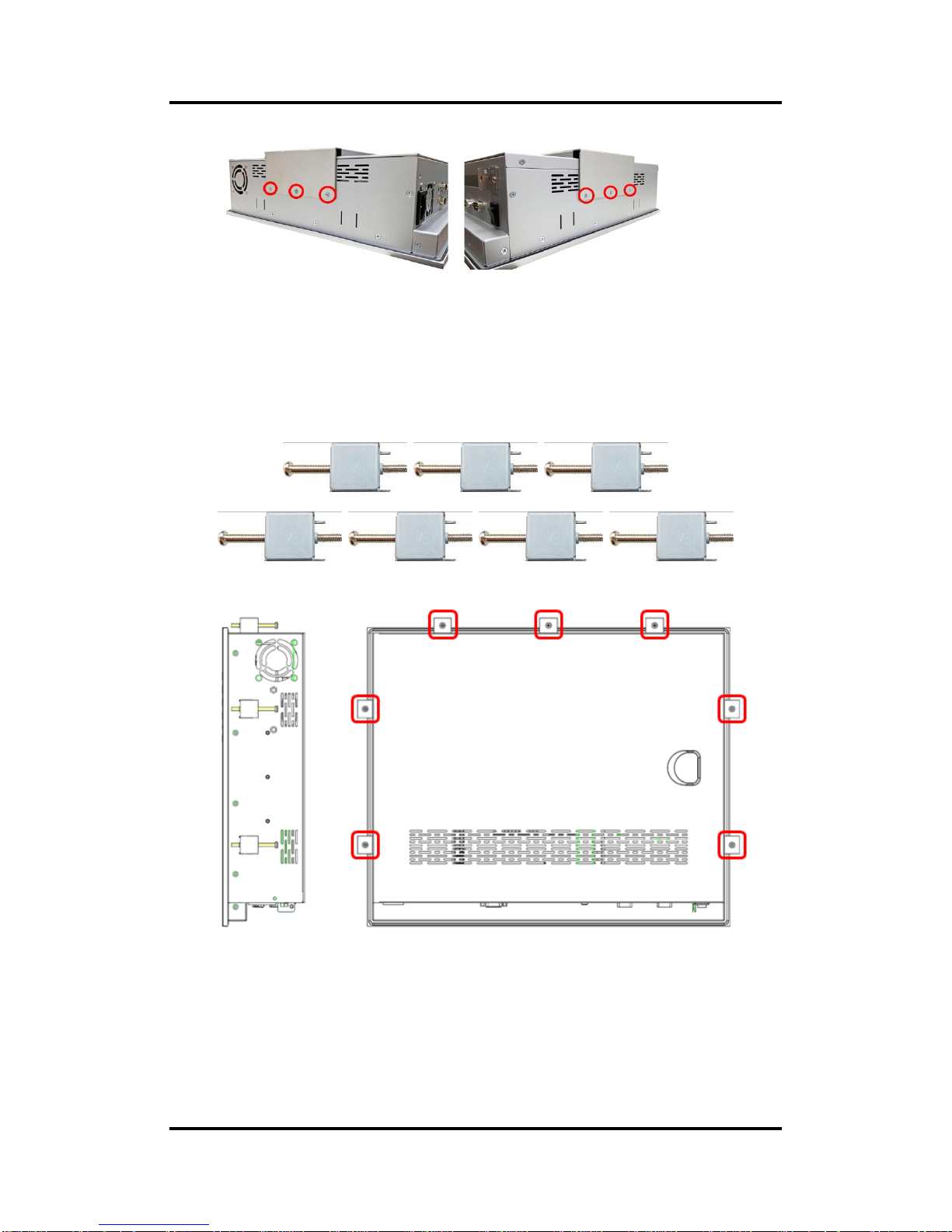
2.4.2 Panel-mount Kit Assembly
The P1177E-842 is designed for panel mount application. To mount the P1177E-842, the
standard set of mounting kit (7pcs included in the system packaging) is needed.
Page 20
P1177E-842 User’s Manual
14 Hardware and Installation
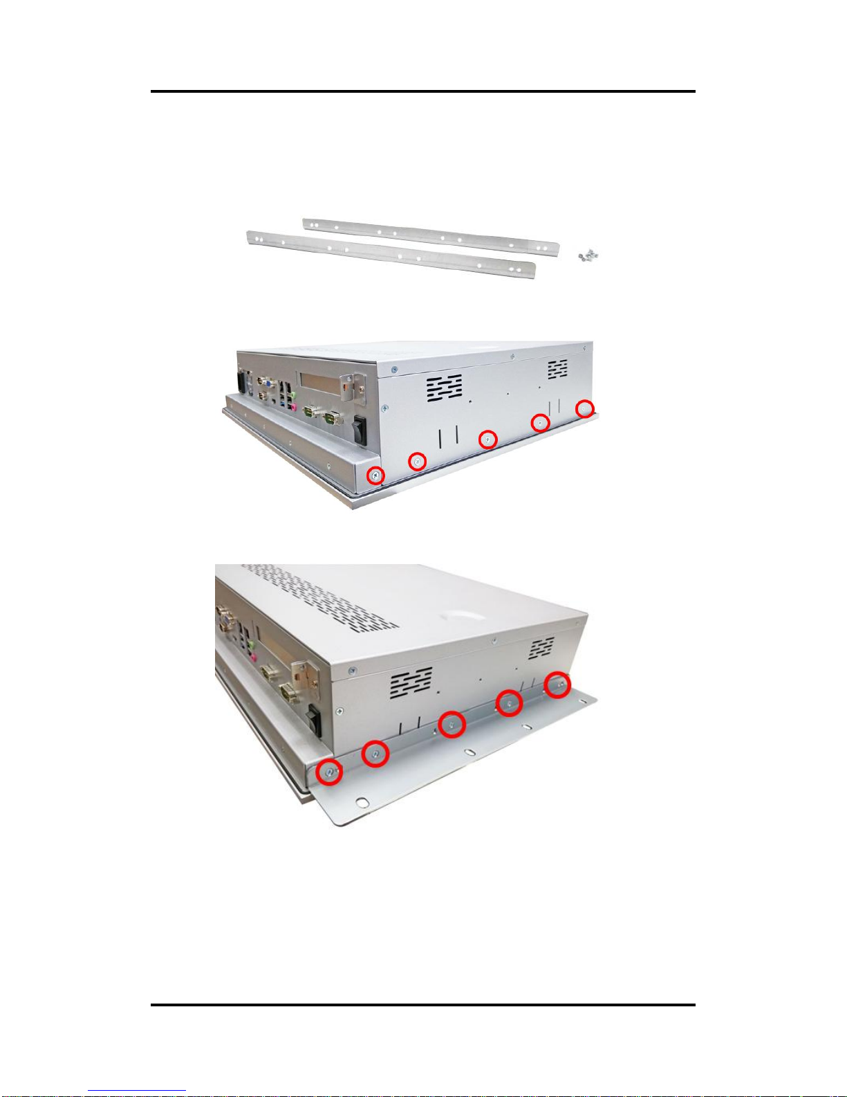
2.4.3 Rack-mount Kit Assembly
The P1177E-842 is designed for rack mount application. To mount the P1177S-871, the
standard set of mounting kit (included in the system packaging) is needed.
Step 1 Unscrew the fix screws from the left and right side of the system.
Step 2 Fixing the rack-mount bracket to the left and right of the system.
Page 21

P1177E-842 User’s Manual
Hardware and Installation 15
2.5 HDD Installation
The P1177E-842 provides a convenient Hard Disk Drive (HDD) bracket for users to install 2.5”
1 x 3.5” or 2.5” SATA HDD. Please follow the steps:
Step 1 Refer section 2.1 to open the back cover.
Step 2 Unscrew 4 screws to take off the HDD bracket.
Step 3 Fix the HDD on bracket by the screws.
▲1 x 3.5” or 2.5” SATA HDD Bracket
▲Fix 3.5” HDD on the back of bracket ▲Fix 2.5” HDD on the back of bracket
Page 22

P1177E-842 User’s Manual
16 Hardware and Installation
Step 4 Fix the HDD bracket into the main base.
Step 5 Plug the power and SATA cables to connectors. Installation completes.
Page 23

P1177E-842 User’s Manual
Hardware and Installation 17
2.6 DRAM Installation
The P1177E-842 provides one 204-pin DDR3L SO-DIMM sockets that support system
memory up to 8GB. Please follow steps below to install the memory modules:
Step 1 Refer to section 2.1 to open the back cover and find out DIMM socket on
mainboard (MANO842).
Step 2 Install the SO-DIMM module into the slot and press it firmly down until it seats
correctly.
Page 24

P1177E-842 User’s Manual
18 Hardware and Installation
Step 3 The slot latches are levered upwards and latch on to the edges of the
SO-DIMM.
Page 25

P1177E-842 User’s Manual
Hardware and Installation 19
2.7 Wireless LAN Module Installation (optional)
The P1177E-842 provides one wireless LAN module to install. When installing the wireless
LAN module, refer to the following instructions and illustration:
Step 1 Refer to section 2.1 to open the back cover and find out PCIe Mini-Card slot
located.
Step 2 Insert wireless LAN module to Mini card slot and fixing it by 1 screw.
Page 26

P1177E-842 User’s Manual
20 Hardware and Installation
Step 3 Find the built-in Antenna cable and connect it wireless LAN card.
Step 4 Lift the rubber stopper from the top of back cover.
Step 5 Install the antenna on the antenna connector.
Page 27

P1177E-842 User’s Manual
Hardware and Installation 21
2.8 Add-on Card Installation
The P1177E-842 provides a riser card (PCIe interface) for 1 x PCIe or 1 x PCI slots expansion.
The riser card assembly can accommodate both half-size expansion cards. To install the riser
card, refer to the following figure and instructions below:
Step 1 Refer section 2.1 to open the back cover and unscrew 2 screws, and then
remove the riser card fix kit and plate.
Step 2 Insert the riser card in the socket firmly until it is completely seated. And,
insert the add-on card you need to the socket of riser card.
Page 28

P1177E-842 User’s Manual
22 Hardware and Installation
Step 3 Secure the metal bracket of the card to the system case with four screws.
Installations complete.
NOTE: Please use the standard size of add-on card to avoid conflicting the mechanism.
Page 29

P1177E-842 User’s Manual
Hardware and Installation 23
2.9 Board Layout
Page 30

P1177E-842 User’s Manual
24 Hardware and Installation
2.10 Rear I/O
1
Front Audio Header (CN31)
20
COM2 Connector (CN18)
2
Internal USB Header (CN3)
21
mSATA Slot (CN28)
3
AT/ATX Power Mode Select Jumper (JP4)
22
PCI-Express x1 Slot (CN26)
4
COM3 Data/Power Select Jumper (JP11)
23
PCI-Express Mini Card Connector (CN27)
5
COM3~COM6 Headers (CN19~CN22)
24
SATA 2.0 Connector (CN4)
6
Power Button Header (CN13)
25
Debug Header (CN2)
7
Fan2 Connector (CN34)
26
DDR3L SO-DIMM Socket (CN23)
8
GPIO Header (CN17)
27
ATX Power Input Connector (CN32)
9
Front Panel Header (CN14)
28
SIM Card Slot (CN5)
10
DC12V/5V Power Output Connector
(CN15)
29
VGA Connector (CN8)
11
Fan1 Connector (CN33)
30
LAN Connectors (CN24~CN25)
12
COM1 RS-232/422/485 Mode Select
Jumpers (JP5~JP7)
31
DC12V Power Input Connector 2 (CN11)
13
DC12V Power Input Connector 1 (CN12)
32
PS/2 Keyboard and Mouse Connector
(CN16)
14
COM2 RS-232/422/485 Mode Select
Jumpers (JP8~JP10)
33
HDMI Connector (CN29)
15
LVDS Backlight Control Header (CN10)
34
USB 3.0 Connector (CN25)
16
LVDS VDD Select Jumper (JP2)
35
USB 2.0 Connector (CN25)
17
LVDS Signal Header (CN9)
36
USB 2.0 Connectors (CN24)
18
LVDS Backlight PWM/CCFL Select Jumper
(JP3)
37
Audio Connector (CN30)
19
COM1 Connector (CN18)
Page 31

P1177E-842 User’s Manual
Hardware and Installation 25
2.11 Jumper Settings
Jumper is a small component consisting of jumper clip and jumper pins. Install jumper clip on 2
jumper pins to close. And remove jumper clip from 2 jumper pins to open. The following
illustration shows how to set up jumper.
Before applying power to MANO842 Series, please make sure all of the jumpers are in factory
default position. Below you can find a summary table of all jumpers and onboard default
settings.
NOTE: Once the default jumper setting needs to be changed, please do it under power-off
condition.
Jumper
Description
Setting
JP1
Clear CMOS
1-2 Close
JP2
LVDS VDD Select
+5V
2-3 Close
JP3
LVDS Backlight PWM/CCFL Select
Default: PWM
1-2 Close
JP4
AT/ATX Power Mode Select
Default: ATX Mode
1-2 Close
JP5
COM1 RS-232/422/485 Mode Select
Default: RS-232
1-2 Close
JP6
3-5, 4-6 Close
JP7
3-5, 4-6 Close
JP8
COM2 RS-232/422/485 Mode Select
Default: RS-232
1-2 Close
JP9
3-5, 4-6 Close
JP10
3-5, 4-6 Close
JP11
COM3 Data/Power Select
Default: RS-232 Data
COM3 Pin 1: DCD#
7-9 Close
COM3 Pin 8: RI#
8-10 Close
Page 32

P1177E-842 User’s Manual
26 Hardware and Installation
2.11.1 Clear CMOS Select (JP1)
This jumper allows you to clear the Real Time Clock (RTC) RAM in CMOS. You can clear the
CMOS memory of date, time, and system setup parameters by erasing the CMOS RTC RAM
data. The onboard button cell battery powers the RAM data in CMOS, which includes system
setup information such as system passwords.
To erase the RTC RAM:
1. Turn OFF the computer and unplug the power cord.
2. Remove the onboard battery.
3. Move the jumper clip from pins 1-2 (default) to pins 2-3. Keep the clip on pins 2-3 for about
5~10 seconds, then move the clip back to pins 1-2.
4. Re-install the battery.
5. Plug the power cord and turn ON the computer.
6. Hold down the <Del> key during the boot process and enter BIOS setup to re-enter data.
2.11.2 LVDS VDD Select (JP2)
This motherboard supports voltage selection for flat panel displays. Use this 3x2-pin
p=2.54mm jumper to set up VDD power of the LVDS connector. To prevent hardware damage,
before connecting please make sure that the input voltage of LVDS panel is correct.
2.11.3 AT/ATX Power Mode Select (JP4)
This 3x1-pin p=2.54mm jumper allows you to select AT or ATX power mode.
Function
Setting
Normal operation (Default)
1-2 close
Clear CMOS
2-3 close
Function
Setting
+3.3V
1-2 close
+5V
3-4 close
+12V
5-6 close
Function
Setting
ATX mode (Default)
1-2 close
AT mode
2-3 close
Page 33

P1177E-842 User’s Manual
Hardware and Installation 27
2.11.4 COM1 RS-232/422/485 Mode Select (JP5, JP6, JP7)
Use these jumpers (3x2-pin p=2.54mm) to set COM1 port to operate as RS-232, RS-422 or
RS-485 communication mode.
2.11.5 COM2 RS-232/422/485 Mode Select (JP8, JP9, JP10)
Use these jumpers (3x2-pin p=2.54mm) to set COM2 port to operate as RS-232, RS-422 or
RS-485 communication mode.
2.11.6 COM3 Data/Power Select (JP11)
The COM3 port has +5V/+12V power capability on DCD and +5V/+12V on RI by setting this
5x2-pin p=2.54mm jumper.
Function
Setting
RS-232 mode
(Default)
JP5 1-2 close
JP6 3-5, 4-6 close
JP7 3-5, 4-6 close
RS-422 mode
JP5 3-4 close
JP6 1-3, 2-4 close
JP7 1-3, 2-4 close
RS-485 mode
JP5 5-6 close
JP6 1-3, 2-4 close
Function
Setting
RS-232 mode
(Default)
JP8 1-2 close
JP9 3-5, 4-6 close
JP10 3-5, 4-6 close
RS-422 mode
JP8 3-4 close
JP9 1-3, 2-4 close
JP10 1-3, 2-4 close
RS-485 mode
JP8 5-6 close
JP9 1-3, 2-4 close
Function
Setting
Power: Set COM3 pin 1 to +12V level
1-3 close
Power: Set COM3 pin 1 to +5V level
3-5 close
Data: Set COM3 pin 1 to DCD# (Default)
7-9 close
Power: Set COM3 pin 8 to +12V level
2-4 close
Power: Set COM3 pin 8 to +5V level
4-6 close
Data: Set COM3 pin 8 to RI# (Default)
9-10 close
Page 34

P1177E-842 User’s Manual
28 Hardware and Installation
This page is intentionally left blank.
Page 35

P1177E-842 User’s Manual
AMI BIOS Setup Utility 29
Chapter 3
AMI BIOS Setup Utility
The AMI UEFI BIOS provides users with a built-in setup program to modify basic system
configuration. All configured parameters are stored in a flash chip to save the setup information
whenever the power is turned off. This chapter provides users with detailed description about
how to set up basic system configuration through the AMI BIOS setup utility.
3.1 Starting
To enter the setup screens, follow the steps below:
1. Turn on the computer and press <Del> during the Power On Self Test (POST) to enter
BIOS setup, otherwise, POST will continue with its test routines.
2. Once you enter the BIOS, the main BIOS setup menu displays. You can access the other
setup screens from the main BIOS setup menu, such as the Advanced and Chipset
menus.
It is strongly recommended that you should avoid changing the chipset’s defaults. Both AMI
and your system manufacturer have carefully set up these defaults that provide the best
performance and reliability.
3.2 Navigation Keys
The BIOS setup/utility uses a key-based navigation system called hot keys. Most of the BIOS
setup utility hot keys can be used at any time during the setup navigation process. These keys
include <F1>, <F2>, <Enter>, <ESC>, <Arrow> keys, and so on.
NOTE: Some of the navigation keys differ from one screen to another.
Hot Keys
Description
Left/Right
The Left and Right <Arrow> keys allow you to select a setup screen.
Up/Down
The Up and Down <Arrow> keys allow you to select a setup screen or sub
screen.
Enter
The <Enter> key allows you to display or change the setup option listed for a
particular setup item. The <Enter> key can also allow you to display the setup
sub screens.
+ Plus/Minus
The Plus and Minus <Arrow> keys allow you to change the field value of a
particular setup item.
F1
The <F1> key allows you to display the General Help screen.
F2
The <F2> key allows you to Load Previous Values.
F3
The <F3> key allows you to Load Optimized Defaults.
F4
The <F4> key allows you to save any changes you have made and exit Setup.
Press the <F4> key to save your changes.
Esc
The <Esc> key allows you to discard any changes you have made and exit the
Setup. Press the <Esc> key to exit the setup without saving your changes.
Page 36

P1177E-842 User’s Manual
30 AMI BIOS Setup Utility
3.3 Main Menu
When you first enter the setup utility, you will enter the Main setup screen. You can always
return to the Main setup screen by selecting the Main tab. System Time/Date can be set up as
described below. The Main BIOS setup screen is shown below.
BIOS Information
Display the BIOS information.
System Date/Time
Use this option to change the system time and date. Highlight System Time or System Date
using the <Arrow> keys. Enter new values through the keyboard. Press the <Tab> key or the
<Arrow> keys to move between fields. The date must be entered in MM/DD/YY format. The
time is entered in HH:MM:SS format.
Access Level
Display the access level of current user.
Page 37

P1177E-842 User’s Manual
AMI BIOS Setup Utility 31
3.4 Advanced Menu
The Advanced menu also allows users to set configuration of the CPU and other system
devices. You can select any of the items in the left frame of the screen to go to the sub menus:
► ACPI Settings
► Super IO Configuration
► Hardware Monitor
► Fan Function
► Display Configuration
► Power Button Control
► S5 RTC Wake Settings
► CPU Configuration
► IDE Configuration
► OS Configuration
► CSM Configuration
► USB Configuration
For items marked with “”, please press <Enter> for more options.
Page 38

P1177E-842 User’s Manual
32 AMI BIOS Setup Utility
ACPI Settings
You can use this screen to select options for the ACPI configuration, and change the value of
the selected option. A description of the selected item appears on the right side of the screen.
Enable ACPI Auto Configuration
Enable or disable BIOS ACPI auto configuration.
Enable Hibernation
Enable or disable system ability to hibernate (OS/S4 sleep state).
ACPI Sleep State
Select the ACPI (Advanced Configuration and Power Interface) sleep state. Configuration
options are Suspend Disabled and S3 (Suspend to RAM). The default setting is S3 (Suspend
to RAM); this option selects ACPI sleep state the system will enter when suspend button is
pressed.
Page 39

P1177E-842 User’s Manual
AMI BIOS Setup Utility 33
Super IO Configuration
You can use this screen to select options for the Super IO Configuration, and change the value
of the selected option. A description of the selected item appears on the right side of the
screen. For items marked with “”, please press <Enter> for more options.
COM1~4
Use these items to set parameters related to serial port 1~4.
Page 40

P1177E-842 User’s Manual
34 AMI BIOS Setup Utility
COM1
Serial Port
Enable or disable serial port 1. The optimal setting for base I/O address is 3F8h and for
interrupt request address is IRQ4.
Change Settings
Select an optimal setting for serial port.
Page 41

P1177E-842 User’s Manual
AMI BIOS Setup Utility 35
Hardware Monitor
This screen monitors hardware health status.
This screen displays the temperature of system and CPU, cooling fans speed in RPM and
system voltages (VCC_CPU, VCC_DDR, +12V, +5V, +3.3V and VBAT).
Page 42

P1177E-842 User’s Manual
36 AMI BIOS Setup Utility
Smart Fan Function
This screen allows you to select the fan mode.
CPU_FAN1 Mode
This item allows you to select the fan mode, which can be set to Full on Mode, Manual Mode,
Auto PWM Mode or Auto RPM Mode.
Page 43

P1177E-842 User’s Manual
AMI BIOS Setup Utility 37
Display Configuration
Primary IGFX Boot Display
Select the video device which will be activated during POST (Power-On Self Test). The default
is Auto.
LVDS Panel Type
Select LVDS panel resolution; see the selection options in image above.
Backlight Control
Select panel backlight control mode.
Brightness
Select the brightness of LVDS panel ranging from 30% to 100%. The default setting is 100%.
Page 44

P1177E-842 User’s Manual
38 AMI BIOS Setup Utility
Power Button Control
Restore AC Power Loss
This item decides the state of system when AC power is resupplied after a power failure. Mode
options are Power Off, Power On and Last State.
Soft-Off by PWR-BTTN
- Instant-Off: The system will shut down instantly when the power button is pressed.
- Delay 4 sec: The system will shut down only when the power button is pressed and held
at least 4 seconds.
PS/2 KB/MS Wake Up From S5
This item decides whether or not the PS/2 keyboard or mouse can wake up the system from
S5 state.
Page 45

P1177E-842 User’s Manual
AMI BIOS Setup Utility 39
S5 RTC Wake Settings
Wake system from S5
Enable or disable system wake on alarm event. It allows you to wake up the system in a
certain time. Select Fixed Time to set the system to wake on the specified time. Use <> <>
to switch among the items: Day, Hour, Minute and Second, and type the value in the selected
item as you wish. For example, if you want the system to start up automatically at 14:25:26, the
13th day of each month, then you should enter 13, 14, 25, and 26 from top to bottom.
Page 46

P1177E-842 User’s Manual
40 AMI BIOS Setup Utility
CPU Configuration
This screen shows the CPU Configuration, and you can change the value of the selected
option.
Socket 0 CPU Information
This item is for CPU information.
Limit CPUID Maximum
This item allows user to limit the maximum value of CPUID. In Windows XP environment, this
item should be disabled.
Intel Virtualization Technology
Enable or disable Intel Virtualization Technology. When enabled, a VMM (Virtual Machine
Mode) can utilize the additional hardware capabilities. It allows a platform to run multiple
operating systems and applications independently, hence enabling a computer system to work
as several virtual systems.
Turbo Mode
Enable or disable the Turbo Mode feature.
Page 47

P1177E-842 User’s Manual
AMI BIOS Setup Utility 41
IDE Configuration
In the IDE Configuration menu, you can see the currently installed hardware in the SATA ports.
During system boot up, the BIOS automatically detects the presence of SATA devices.
Serial-ATA (SATA)
Enable or disable the SATA controller feature.
SATA Speed Support
Select SATA speed support.
SATA Mode
Determine how SATA controller(s) operate. Operation mode options are IDE Mode, AHCI
(Advanced Host Controller Interface) Mode. The default is AHCI Mode.
SATA 1~2
Enable or disable the onboard SATA port 1~2.
Page 48

P1177E-842 User’s Manual
42 AMI BIOS Setup Utility
OS Configuration
OS Selection
This item allows user to select the proper Operating System.
Page 49

P1177E-842 User’s Manual
AMI BIOS Setup Utility 43
CSM Configuration
CSM Support
Enable or disable CSM (Compatibility Support Module) support.
PXE BootRom
Enable or disable the Preboot eXecution Environment (PXE) boot ROM function of the
onboard LAN chip during system boots up.
Page 50

P1177E-842 User’s Manual
44 AMI BIOS Setup Utility
USB Configuration
Legacy USB Support
Use this item to enable or disable legacy support for USB devices. The default setting is
Enabled. Auto option disables legacy support if no USB devices are connected. Disable option
will keep USB devices available only for EFI applications.
Page 51

P1177E-842 User’s Manual
AMI BIOS Setup Utility 45
3.5 Chipset Menu
The Chipset menu allows users to change the advanced chipset settings. You can select any
of the items in the left frame of the screen to go to the sub menus:
► North Bridge
► South Bridge
For items marked with “”, please press <Enter> for more options.
Page 52

P1177E-842 User’s Manual
46 AMI BIOS Setup Utility
North Bridge
IGD Turbo Enable
Enable or disable the IGD Turbo feature.
This screen shows system memory information.
Page 53

P1177E-842 User’s Manual
AMI BIOS Setup Utility 47
South Bridge
This screen allows users to configure parameters of South Bridge chipset.
Page 54

P1177E-842 User’s Manual
48 AMI BIOS Setup Utility
Azalia HD Audio
Disable=Azalia will be unconditionally Disable
Enable=Azalia will be unconditionally Enable
Page 55

P1177E-842 User’s Manual
AMI BIOS Setup Utility 49
USB Configuration
XHCI Mode
Enable/Disable or select Auto/Smart Auto XHCI Mode feature.
USB 2.0(EHCI) can select Enable when XHCI mode is disabled.
Page 56

P1177E-842 User’s Manual
50 AMI BIOS Setup Utility
PCI Express Configuration
PCI Express port 0~3 can select Enable or Disable
Speed can select Gen1/Gen2 or Auto
Page 57

P1177E-842 User’s Manual
AMI BIOS Setup Utility 51
3.6 Security Menu
The Security menu allows users to change the security settings for the system.
Administrator Password
This item indicates whether an administrator password has been set (installed or uninstalled).
User Password
This item indicates whether a user password has been set (installed or uninstalled).
HDD Security Configuration
This item indicates whether the HDD password has been set (installed or uninstalled)
Page 58

P1177E-842 User’s Manual
52 AMI BIOS Setup Utility
3.7 Boot Menu
The Boot menu allows users to change boot options of the system.
Setup Prompt Timeout
Number of seconds to wait for setup activation key. 65535(0xFFFF) means indefinite waiting.
Bootup NumLock State
Use this item to select the power-on state for the keyboard NumLock.
FullScreen Logo
Enable or disable OEM logo display at system startup.
Fast Boot
Enable or disable fast boot function. BIOS skips some certain procedures to decrease system
boot up time.
Boot Option Priorities [Boot Option #1, …]
These are settings for boot priority. Specify the boot device priority sequence from the
available devices.
Hard Drive BBS Priorities
These are define the boot order for the hard drive
Page 59

P1177E-842 User’s Manual
AMI BIOS Setup Utility 53
3.8 Save & Exit Menu
The Save & Exit menu allows users to load your system configuration with optimal or fail-safe
default values.
Save Changes and Reset
When you have completed the system configuration changes, select this option to leave Setup
and reboot the computer so the new system configuration parameters can take effect. Select
Save Changes and Reset from the Save & Exit menu and press <Enter>. Select Yes to save
changes and reset.
Discard Changes and Reset
Select this option to quit Setup without making any permanent changes to the system
configuration and reboot the computer. Select Discard Changes and Reset from the Save &
Exit menu and press <Enter>. Select Yes to discard changes and reset.
Restore Defaults
It automatically sets all Setup options to a complete set of default settings when you select this
option. Select Restore Defaults from the Save & Exit menu and press <Enter>.
Save as User Defaults
Select this option to save system configuration changes done so far as User Defaults. Select
Save as User Defaults from the Save & Exit menu and press <Enter>.
Restore User Defaults
It automatically sets all Setup options to a complete set of User Defaults when you select this
option. Select Restore User Defaults from the Save & Exit menu and press <Enter>.
Page 60

P1177E-842 User’s Manual
54 AMI BIOS Setup Utility
Boot Override
Select a drive to immediately boot that device regardless of the current boot order.
Launch EFI Shell from filesystem device
Attempt to launch EFI Shell application (Shellx64.efi) from one of the available filesystem
devices.
Page 61

P1177E-842 User’s Manual
Drivers Installation
55
Chapter 4
Drivers Installation
4.1 System
P1177E-842 supports Windows 7 / Windows 8.1 / WES7 / WE8S. To facilitate the installation of
system driver, please carefully read the instructions in this chapter before start installing.
Step 1 Insert Driver CD and select the “\Drivers”.
Step 2 Select all files and follow the installing procedure.
4.2 Touch Screen
The P1177E-842 uses the 5-wire analog resistive. There are the specification and driver
installation which are listed below.
Specification
Touch Screen
5-wire Analog Resistive type
Touch Screen Controller
PenMount 6500 USB Touch Screen Controller IC
Communications
USB interface
Baud Rate
19200 baud rate fixed
Resolution
1280 X 1024
Page 62

P1177E-842 User’s Manual
Drivers Installation
56
Driver Installation- Windows 7 / 8.1
The P1177E-842 provides a touch screen driver that users can install it under the operating
system Windows 7. To facilitate installation of the touch screen driver, you should read the
instructions in this chapter carefully before you attempt installation.
Step 1 Insert Driver CD and follow the path to select the “\Drivers\Step 7. Touch”.
Step 2 Follow the installing procedure and press OK.
Step 3 Click Start menu and select “PenMount Utilities”; and then, a “PenMount
Control Panel” pops out.
Page 63

P1177E-842 User’s Manual
Drivers Installation
57
Step 4 Click “Configure”
Step 5 Select the “Standard Calibrate” tab.
Page 64

P1177E-842 User’s Manual
Drivers Installation
58
Step 6 Calibrations:
To adjust the display with touch panel, click “Calibration” and follow the calibrate
point to do calibration; there are five points on screen for calibration.
Step 7 Press OK.
Page 65

P1177E-842 User’s Manual
Drivers Installation
59
4.3 Embedded O.S.
The P1177E-842 provides the Windows 7 Embedded and Windows Embedded 8 Standard.
The O.S. is supported devices which are listed below.
WES7 / WE8S
Here are supported onboard devices:
Onboard Multi I/O
SATA HDD
USB
PS2 Keyboard and mouse
CRT/LCD display
10/100/1000 base-T Ethernet
Onboard Audio
Touch Screen
PenMount Touch screen
Before you can use and calibrate it, here is what you should do:
1. Set up Penmount touch device driver by executing C:\Penmount\ Windows 2000-XP
V5.0\setup.exe. When the installation is finished, an icon “PM” appears on the Taskbar.
2. Calibrate Penmount touch by clicking on the “PM” icon, and the go on the calibration.
3. Restart the computer.
 Loading...