

Page 1

P1127E-500
All-in-One
12.1” XGA TFT Expandable
Panel PC
User’s Manual
Page 2

ii
Disclaimers
This manual has been carefully checked and believed to contain accurate information.
Axiomtek Co., Ltd. assumes no responsibility for any infringements of patents or rights of any
third party, or any liability arising from such use.
Axiomtek does not warrant or assume any legal liability or responsibility for the accuracy,
completeness or usefulness of any information in this document. Axiomtek does not make any
commitment to update the information in this manual.
Axiomtek reserves the right to change or revise this document and/or product at any time
without notice.
No part of this document may be reproduced, stored in a retrieval system, or transmitted, in
any form or by any means, electronic, mechanical, photocopying, recording, or otherwise,
without prior written permission from Axiomtek Co., Ltd.
CAUTION
Wrong type of batteries may cause explosion. It is recommended that users only replace with
the same or equivalent type of batteries as suggested by the manufacturer once properly
disposing of any used ones.
Copyright 2018 Axiomtek Co., Ltd.
All Rights Reserved
January 2018, Version A1
Printed in Taiwan
Page 3

iii
Safety Precautions
Before getting started, please read the following important safety precautions.
1. Be sure to ground yourself to prevent static charge when installing the internal
components. Use a grounding wrist strap and place all electronic components in any
static-shielded devices. Most electronic components are sensitive to static electrical
charge.
2. Disconnect the power cord from the P1000 series prior to any installation. Be sure both
the system and the external devices are turned off. Sudden surge of power could ruin
sensitive components. Make sure the P1000 series is properly grounded.
3. Do not open the top cover of the system. If opening the cover for maintenance is a must,
only a trained technician is allowed to do so. Integrated circuits on computer boards are
sensitive to static electricity. To avoid damaging chips from electrostatic discharge,
observe the following precautions:
Before handling a board or integrated circuit, touch an unpainted portion of the system
unit chassis for a few seconds. This will help to discharge any static electricity on a
human body.
When handling boards and components, wear a grounding wrist strap available
from most electronic component stores.
Trademark Acknowledgments
Axiomtek is a trademark of Axiomtek Co., Ltd.
Windows® is a trademark of Microsoft Corporation.
IBM, PC/AT, PS/2, VGA are trademarks of International Business Machines Corporation.
Intel® and Pentium® are trademarks of Intel Corporation.
AMI is trademark of American Megatrend Inc.
Other brand names and trademarks are the properties and registered brands of their
respective owners.
Page 4

iv
Table of Contents
Disclaimers ..................................................................................................... ii
Safety Precautions ........................................................................................ iii
Section 1 Introduction ............................................. 1
1.1 General Description ............................................................................ 1
1.2.1 System Specifications ...................................................................................... 2
1.2.2 Mechanical/Environmental Specifications ........................................................ 3
1.3 Dimensions and Outlines ................................................................... 4
1.4 I/O Outlets ............................................................................................ 6
Section 2 Hardware and Installation ...................... 9
2.1 Packing List ....................................................................................... 10
2.2 System Layout ................................................................................... 10
2.3 Mountings: Panel / Wall / Rack / Desktop / VESA ........................... 12
2.3.1 VESA-ARM / Wall-Mount / Desktop-mount.................................................... 12
2.3.2 Panel-mount Kit Assembly ............................................................................. 13
2.4 HDD Installation ................................................................................. 14
2.5 DRAM Installation .............................................................................. 16
2.6 Wireless LAN Module Installation (optional) ................................... 17
2.7 Add-on Card Installation ................................................................... 19
2.8 Board Layout ..................................................................................... 21
2.9 Rear I/O .............................................................................................. 22
2.10 Jumper Settings ................................................................................ 23
2.10.1 Clear CMOS Select (JP1) ................................................................................ 24
2.10.2 AT/ATX Power Mode Select (JP2) ................................................................... 24
2.10.3 COM1 RS-232/422/485 Mode Select (JP3, JP4, JP5) .................................... 24
2.10.4 COM1 Data/Power Select (JP6) ...................................................................... 25
2.11 Connectors ........................................................................................ 26
2.11.1 Audio Jack (CN2) ............................................................................................. 27
2.11.2 LAN and USB 3.0 Connectors (CN3 and CN4) ............................................... 27
2.11.3 DisplayPort Connector (CN5) .......................................................................... 28
2.11.4 VGA Connector (CN6) ..................................................................................... 28
2.11.5 COM Connector (CN7) .................................................................................... 29
2.11.6 HDMI Connector (CN8) ................................................................................... 30
2.11.7 PCI-Express Mini Card Connector (CN11) ...................................................... 31
2.11.8 USB 2.0 Wafers (CN13 and CN14) ................................................................. 32
2.11.9 CMOS Battery Connector (BAT1) .................................................................... 32
Page 5

v
2.11.10 Fan Connectors (CPU_FAN1 and SYS_FAN1) ............................................. 33
2.11.11 SIM Card Slot (SIM1) ..................................................................................... 34
2.11.12 SATA 3.0 Connectors (SATA1~SATA3) ......................................................... 34
Section 3 AMI BIOS Setup Utility .......................... 35
3.1 Starting ............................................................................................... 35
3.2 Navigation Keys ................................................................................ 35
3.3 Main Menu ........................................................................................ 36
3.4 Advanced Menu ................................................................................. 37
3.5 Chipset Menu ..................................................................................... 47
3.6 Security Menu .................................................................................... 50
3.7 Boot Menu .......................................................................................... 51
3.8 Save & Exit Menu ............................................................................... 52
Section 4 Driver Installation ................................ 55
4.1 System ............................................................................................... 55
4.2 Touch Screen ................................................................ ..................... 56
4.3 Embedded OS .................................................................................... 60
Appendix BIOS Flash Utility ................................ 61
Page 6

vi
This page is intentionally left blank.
Page 7
P1127E-500 User’s Manual
Introduction 1
Section 1
Introduction
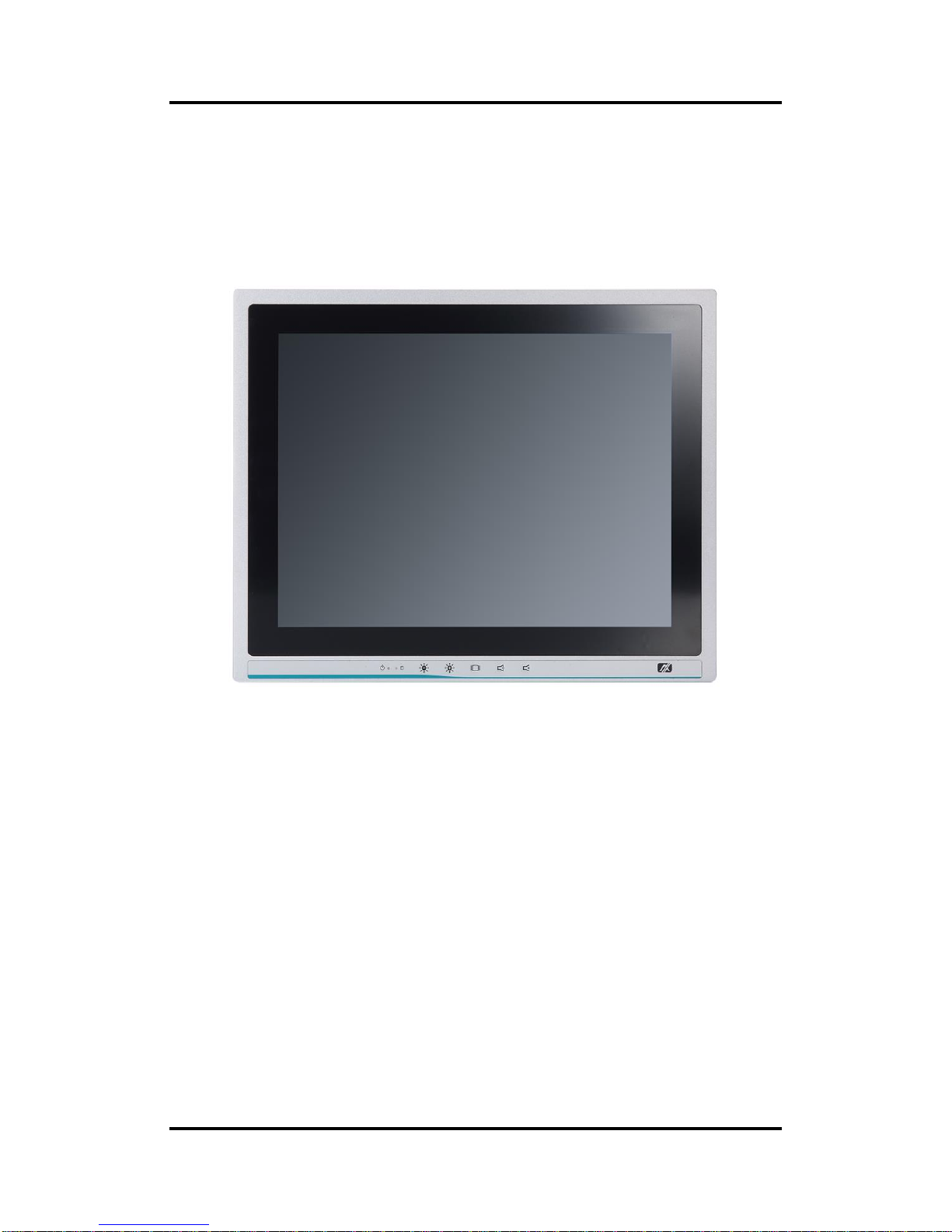
This Section contains general information and detailed specifications of the P1127E-500,
including the following subsections:
Figure 1-1 Front view of the P1127E-500
General Description
Specification
Dimensions
I/O Outlets
Package List
1.1 General Description
The P1127E-500 adopts a 12.1-inch XGA TFT LCD with 500-nits brightness, a
high-performance LGA1151 socket for 7th and 6th generation Intel® Core™ processors, and
an Intel® H110 Express chipset to provide excellent computing performance. Furthermore, the
P1127E-500 comes with a built-in speaker and an optional WLAN module for wireless
connectivity.
Industrial-grade front bezel
The P1127E-500 adopts an industrial-grade front bezel which incorporates the advantages of
light weight, high degree of hardness, better heat releasing, easy-to-shape and anti-corrosion
features, making the P1127E-500 especially suitable for most rugged industrial environments.
Expandable for PCIe (or PCI optional)
The P1127E-500 comes with one PCIe x4 (or optionally one PCI) for expansion purposes.
Users can easily plug in a standard half-size PCI or PCIe card as required.
Page 8

P1127E-500 User’s Manual
2 Introduction
Speaker and WLAN Antenna Supported
The P1127E-500 features a built-in speaker for kiosk applications to display multimedia
contents. It also supports a WLAN module antenna (optional) for wireless network connectivity.
High Performance computing: 7th and 6th Generation Intel® Core™ Processors
The P1127E-500 is powered by LGA1151 Socket 7th and 6th Generation Intel® Core™ i7/i5/i3,
Pentium® and Celeron® processors which provide powerful performance and less power
consumption. The latest Intel® Kaby Lake-S platform offers reliable and stable performance
suitable for rugged environments.
1.2.1 System Specifications
Main CPU Board
CPU
LGA1151 socket 7th and 6th generation Intel® Core™ i7/i5/i3, Celeron® and
Pentium® processors
Chipset
Intel® H110 PCH chipset
System Memory
Skylake:
2 x 288-pin DDR4-2133 Long-DIMM socket support dual channels up to 32GB
Kabylake:
2 x 288-pin DDR4-2400 Long-DIMM socket support dual channels up to 32GB
BIOS
AMI BIOS
Standard I/O
1 x RS-232/422/485
3 x RS-232
4 x USB 3.0
1 x HDMI
1 x VGA
1 x Display Port
2 x USB2.0
1 x Remote Power Switch
Ethernet
1 x RJ45 GbE LAN ports (Intel® i219LM)
1 x RJ45 GbE LAN ports (Intel® i211AT)
Audio
1 x Line-out
1 x Mic-in
Expansion
1 x PCIe x4 or 1 x PCI slot.
1 x PCI-Express Mini Card; only WIFI and 3G supported.
1 x SIM card slot.
3 x SMA Type Antenna Hole
Page 9

P1127E-500 User’s Manual
Introduction 3
Storage
1 x 2.5” SATA HDD
Power connector
1 x AC plug
1.2.2 Mechanical/Environmental Specifications
12.1” XGA LCD (with resolutions 1024x768)
5 wired resistive touch
IP65/NEMA4 aluminum front bezel
Net Weight
4.2 Kgs (9.26 lbs)
Dimensions (Main Body Size)
314.2mm x 105mm x 253.7mm (12.37" x 4.13" x 9.99" ) (W x D x H)
Operation Temperature
0°C to 50°C
Relative Humidity
10% to 90% @ 40°C, non-condensing
Power Input
100~240VAC power connector
NOTE 1. All specifications and images are subject to change without notice.
2. Long pressing the button of OSD doesn’t have the “repeat” function.
Page 10

P1127E-500 User’s Manual
4 Introduction
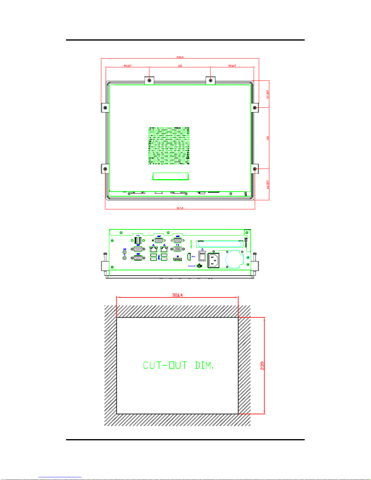
1.3 Dimensions and Outlines
Diagram 1-1 and 1-2 show the outlines and dimensions of the P1127E-500, respectively.
Diagram 1-1 Outlines of the P1127E-500
.
Page 11
P1127E-500 User’s Manual
Introduction 5
Diagram 1-2 Outlines of the P1127E-500
Page 12
P1127E-500 User’s Manual
6 Introduction
1.4 I/O Outlets
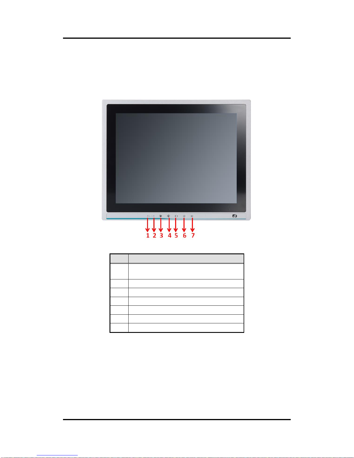
Figure 1-2, 1-3 and Table 1-1, 1-2 illustrate the I/O locations of the P1127E-500 and their
functions.
Figure 1-2 Front view of the P1127E-500
Table 1-1 Functions of the front panel of the P1127E-500
No
Function
1
1 x Display status LED
(Red: display off, Green: display on)
2
1 x SATA status LED
3
1 x Brightness down
4
1 x Brightness up
5
1 x Display monitor ON/OFF
6
1 x Volume down
7
1 x Volume up
Page 13

P1127E-500 User’s Manual
Introduction 7
Figure 1-3 Side view of the P1127E-500
Table 1-2 Functions of the I/O Outlets of the P1127E-500
No
Function
1
1 x Line-out
2
2 x USB2.0
3
2 x RJ45 for Gigabit Ethernet
4
1 x RS-232 (COM3)
1 x RS-232 (COM4)
5
1 x PCI or 1 x PCIe x4 card expansion slot
6
1 x Mic-in
7
1 x RS-232/422/485 (COM1)
1 x RS-232 (COM2)
8
4 x USB3.0
9
1 x VGA
10
1 x Display Port
11
1 x HDMI
12
1 x Switch for power on/off
13
1 x Remote switch button
14
1 x AC plug
Page 14

P1127E-500 User’s Manual
8 Introduction
This page is intentionally left blank.
Page 15

P1127E-500 User’s Manual
Hardware and Installation 9
Section 2
Hardware and Installation
The P1127E-500 provides rich I/O ports and flexible expansion to meet different demands. The
section explains how to install the hardware.
Packing List
System Layout
Mountings: Panel / Wall / Rack / Desktop / VESA
HDD Installation
DRAM Installation
Wireless LAN Module Installation (optional)
Add-on Card Installation
Board Layout
Rear I/O
Jumper Settings
Connector
Page 16
P1127E-500 User’s Manual
10 Hardware and Installation
2.1 Packing List
The package bundled with the P1127E-500 should contain the following items:
P1127E-500 x 1
Driver CD x 1
Panel mount kits x 6
Wall mount / VESA mount bracket x 1 (optional)
Remote power switch cable x1
Power cord x 1
If any above-mentioned item is missing, please contact an Axiomtek distributor immediately.
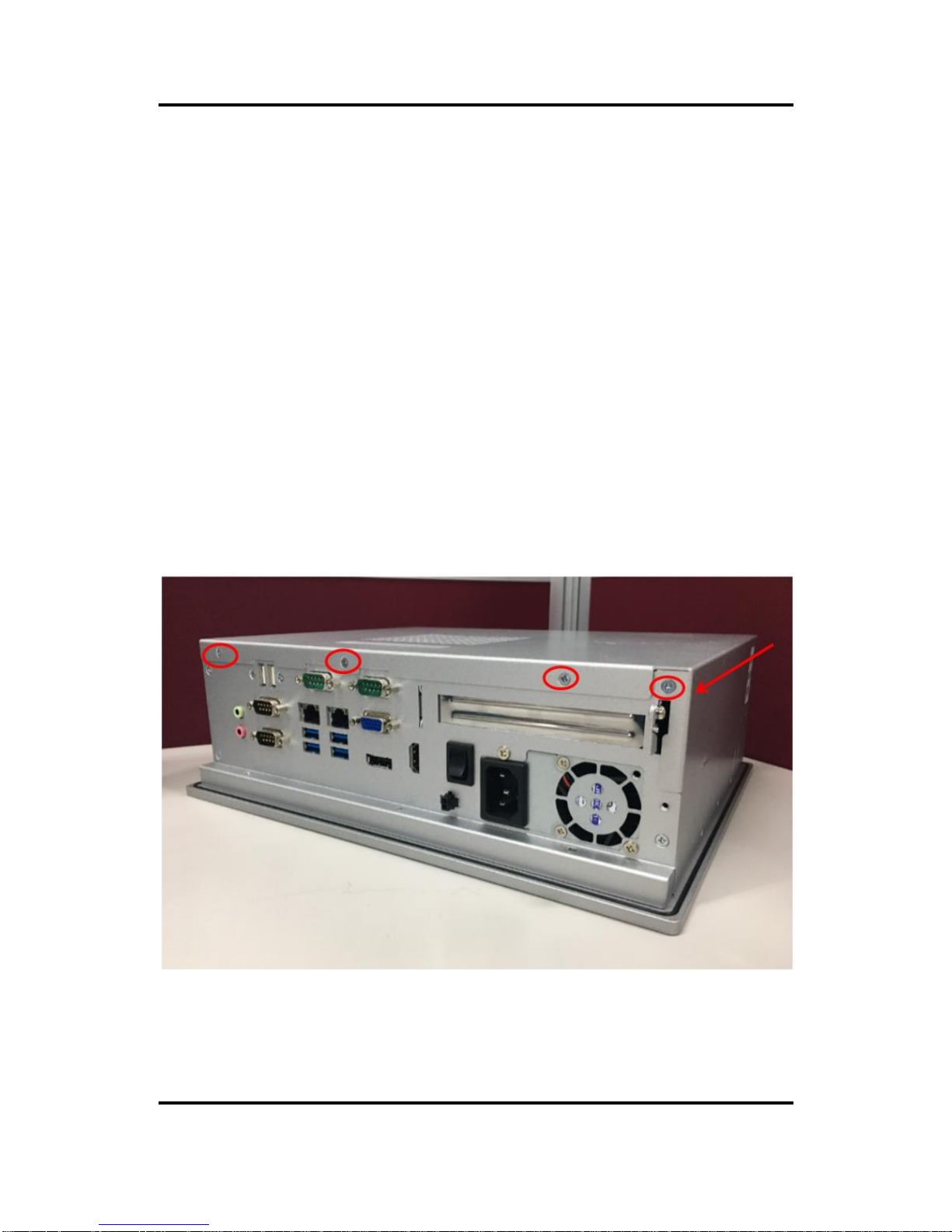
2.2 System Layout
To open the P1127E-500, simply unscrew the four screws on the back cover as shown in Figure
2-1, and then push the cover to the right side.
Figure 2-1 Removing the back cover of the P1127E-500
Page 17
P1127E-500 User’s Manual
Hardware and Installation 11
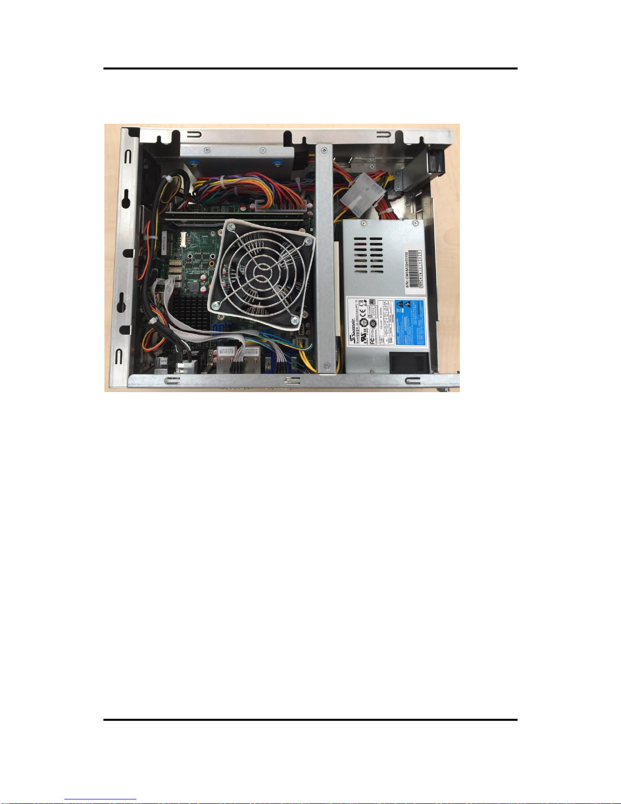
Once the back cover is removed, the internal system should look like Figure 2-2.
Figure 2-2 After Removing the back cover of the P1127E-500, install memory, storage and
any other peripherals.
Page 18

P1127E-500 User’s Manual
12 Hardware and Installation
2.3 Mountings: Panel / Wall / Rack / Desktop / VESA
There are 5 application options for the P1127E-500, including Panel/Wall/Rack/ Desktop/VESA
mounting ways.
2.3.1 VESA-ARM / Wall-Mount / Desktop-mount
The P1127E-500 provides VESA mount: 75x75 mm or 100x100mm. Screw six screws to fix the kit
in the back chassis.
▲Bracket for VESA/wall/desktop mount
▲Putting the bracket on the back of the system
Page 19
P1127E-500 User’s Manual
Hardware and Installation 13
▲Fixing the bracket by screwing the six screws on the left and right sides.
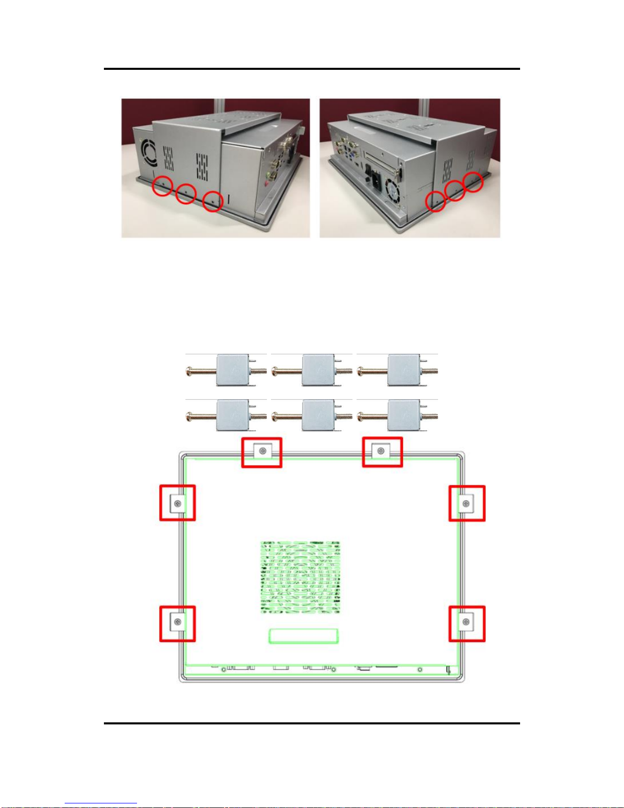
2.3.2 Panel-mount Kit Assembly
The P1127E-500 is designed for panel mount application. To mount the P1127E-500, the standard
set of the mounting kit (6 pieces included in the system packaging) is needed.
Page 20
P1127E-500 User’s Manual
14 Hardware and Installation
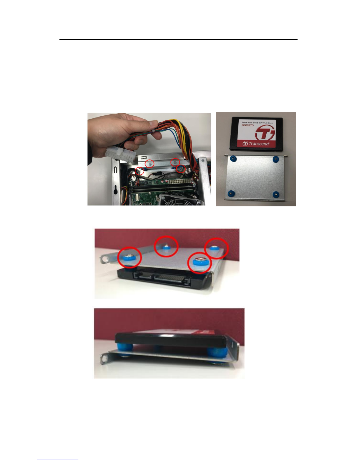
2.4 HDD Installation
The P1127E-500 provides a convenient hard disk drive (HDD) bracket for users to install 1 x 2.5”
SA TA HDD. Please follow the steps:
Step 1 Refer section 2.1 to open the back cover.
Step 2 unplug the power cable and unscrew the 4 screws to take off the HDD bracket.
Step 3 Fix the HDD on the bracket with the 4 screws, as shown in the figures below.
Page 21
P1127E-500 User’s Manual
Hardware and Installation 15
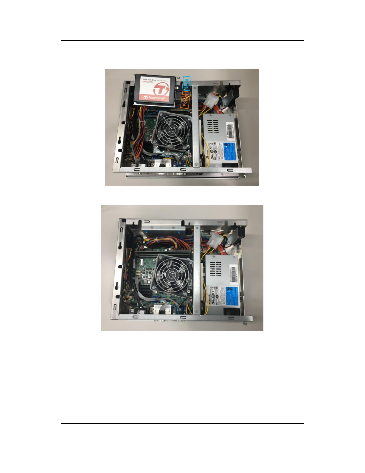
Step 4 Plug the power and SATA cables to the connectors.
Step 5 Fix the HDD bracket into the main base. Installation is completed.
Page 22

P1127E-500 User’s Manual
16 Hardware and Installation
2.5 DRAM Installation
The P1127E-500 provides one 288-pin DDR4 Long-DIMM socket that supports system memory
up to 32GB. Please follow the steps below to install the memory modules.
Step 1 Refer to section 2.1 to open the back cover and locate the DIMM socket on
mainboard (MANO500).
Step 2 Install the Long-DIMM module into the slot and press it down until it firmly sits in
place.
Step 3 The slot latches are levered upwards and latch on to the edges of the
Long-DIMM.
Page 23

P1127E-500 User’s Manual
Hardware and Installation 17
2.6 Wireless LAN Module Installation (optional)
The P1127E-500 provides one wireless LAN module to install. When installing the wireless LAN
module, refer to the following instructions and illustrations:
Step 1 Refer to section 2.1 to open the back cover and locate the PCIe Mini-Card slot.
Step 2 Insert the wireless LAN module into Mini card slot and fix it with one screw.
Page 24

P1127E-500 User’s Manual
18 Hardware and Installation
Step 3 Find the built-in antenna cable and connect it to the wireless LAN module.
Step 4 Lift the rubber stopper from the top of the back cover.
Step 5 Install the antenna on the antenna connector.
Page 25

P1127E-500 User’s Manual
Hardware and Installation 19
2.7 Add-on Card Installation
The P1127E-500 provides a riser card (PCIe interface) for 1 x PCIe or 1 x PCI slots expansion.
The riser card assembly can accommodate both half-size expansion cards. To install the riser card,
refer to the following figures and instructions.
Step 1 Refer section 2.1 to open the back cover and unscrew three screws, and then
remove the riser card fix kit and plate.
Step 2 Insert the riser card in the socket firmly until it is installed completely. Then
insert the add-on card to the socket of the riser card.
Page 26

P1127E-500 User’s Manual
20 Hardware and Installation
Step 3 Secure the metal bracket of the card to the system case with two screws.
Installation is completed.
NOTE: Please use a standard-sized add-on card to avoid conflict to the mechanism.
Page 27

P1127E-500 User’s Manual
Hardware and Installation 21
2.8 Board Layout
Page 28

P1127E-500 User’s Manual
22 Hardware and Installation
2.9 Rear I/O
Table 2-1 Jumpers/Headers/Connectors associated with each Label
Jumpers/Headers/Connectors
Label
Function
Label
Function
1
Clear CMOS Jumper (JP1)
12
PCI-Express x16 Slot (CN1)
2
COM3~COM4 Headers (COM3~COM4)
13
SATA 3.0 Connectors (SATA1~SATA3)
3
AT/ATX Power Mode Select Jumper
(JP2)
14
CPU Socket
4
USB 2.0 Wafers (CN13, CN14)
16
Audio Jack (CN2)
5
CPU Fan Connector (CPU_FAN1)
17,18
COM1 and COM2 Connector (CN7)
6
CMOS Battery Connector (BAT1)
19
LAN Connectors (CN3, CN4)
7
COM1 RS-232/422/485 Mode Select
Jumpers (JP3~JP5)
20
USB 3.0 Connectors (CN3, CN4)
8
COM1 Data/Power Select Jumper (JP6)
21
VGA Connector (CN6)
9
PCI-Express Mini Card Connector
(CN11)
22
DisplayPort Connector (CN5)
10
SIM Card Slot (SIM1)
23
HDMI Connector (CN8)
11
DDR4 LONG-DIMM Sockets (DIMM1,
DIMM2)
NOTE:
To identify the first pin of a header or jumper, please refer to the following information:
Usually, there is a thick line or a triangle near the header or jumper pin 1.
A square, which you can find on the back of the motherboard, is usually used for pin 1.
Page 29

P1127E-500 User’s Manual
Hardware and Installation 23
2.10 Jumper Settings
A jumper is a small component consisting of a jumper clip and jumper pins. Install a jumper clip on
two jumper pins to close the pins. And remove the jumper clip from two jumper pins to open the
pins. Diagram 2-1 illustrates how to set up a jumper.
Diagram 2-1 Definitions of Pin Settings
Before applying power to the P1127E-500 series, please make sure all of the jumpers are in
default positions which are defined as follows:
NOTE: In case that default jumper settings need to be changed, please make any change
under the power-off condition.
Table 2-2 Jumper settings
Jumper
Description
Setting
JP1
Clear CMOS
Default: Normal Operation
1-2 Close
JP2
AT/ATX Power Mode Select
Default: ATX Mode
1-2 Close
JP3
COM1 RS-232/422/485 Mode Select
Default: RS-232
1-2 Close
JP4
3-5, 4-6 Close
JP5
3-5, 4-6 Close
JP6
COM3 Data/Power Select
Default: RS-232 Data
CN7 Pin 1: DCD
3-5 Close
CN7 Pin 9: RI
4-6 Close
Page 30

P1127E-500 User’s Manual
24 Hardware and Installation
2.10.1 Clear CMOS Select (JP1)
JP1 is used to clear the Real Time Clock (RTC) RAM in CMOS. Data, time and system setup
parameters stored in the CMOS memory can be cleared by erasing the CMOS RTC RAM data.
The onboard battery powers the RAM data in CMOS, which includes system setup information
such as system passwords.
To erase the RTC RAM:
1. Turn off the computer and unplug the power cord.
2. Remove the onboard battery.
3. Move the jumper clip from Pins 1-2 (default) to Pins 2-3. Keep the clip on Pins 2-3 for about
5~10 seconds, then move the clip back to Pins 1-2.
4. Re-install the battery.
5. Plug the power cord and turn on the computer.
6. Hold down the <Del> key during the boot process and enter BIOS setup to re-enter data.
Table 2-3 Jumper settings for JP1
2.10.2 AT/ATX Power Mode Select (JP2)
JP2, a 3x1-pin p=2.54mm jumper, is used to select AT or ATX power mode.
Table 2-4 Jumper settings for JP2
2.10.3 COM1 RS-232/422/485 Mode Select (JP3, JP4, JP5)
Use Jumpers 3, 4 and 5 (3x2-pin p=2.54mm) to set COM1 port to operate as RS-232, RS-422 or
RS-485 communication mode.
Table 2-5 Jumper Settings for JP3, JP4 and JP5
Function
Setting
Normal operation (Default)
1-2 close
Clear CMOS
2-3 close
Function
Setting
ATX mode (Default)
1-2 close
AT mode
2-3 close
Function
Setting
RS-232 mode
(Default)
JP3 1-2 close
JP4 3-5, 4-6 close
JP5 3-5, 4-6 close
RS-422 mode
JP3 3-4 close
JP4 1-3, 2-4 close
JP5 1-3, 2-4 close
RS-485 mode
JP3 5-6 close
JP4 1-3, 2-4 close
JP5 1-3, 2-4 close
Page 31

P1127E-500 User’s Manual
Hardware and Installation 25
2.10.4 COM1 Data/Power Select (JP6)
The COM1 port has the +5V power capability on DCD and +12V on RI by setting this jumper
(3x2-pin p=2.54mm).
Table 2-6 Jumper Settings for JP6
Function
Setting
Power: Set COM1 Pin 1 to +5V
1-3 close
Data: Set COM1 Pin 1 to DCD (Default)
3-5 close
Power: Set COM1 Pin 9 to +12V
2-4 close
Data: Set COM1 Pin 9 to RI (Default)
4-6 close
Page 32

P1127E-500 User’s Manual
26 Hardware and Installation
2.11 Connectors
Signals go to other parts of the system through connectors. Loose or improper connection may
cause problems or malfunctions, Ensure that all connectors are properly and firmly connected.
Table 2-7 is a summary listing the connectors on the hardware.
Table 2-7 A summary of the connectors
Connector
Description
CN1
PCI-Express x16 Slot
CN2
Audio Jack
CN3, CN4
LAN and USB 3.0 Connectors
CN5
DisplayPort Connector
CN6
VGA Connector
CN7
COM1 and COM2 Connector
CN8
HDMI Connector
CN11
PCI-Express Mini Card Connector
CN13, CN14
USB 2.0 Wafers
BAT1
CMOS Battery Connector
CPU_FAN1
CPU Fan Connector
SYS_FAN1
System Fan Connector
SIM1
SIM Card Slot
SATA1~SATA3
SATA 3.0 Connectors
DIMM1~DIMM2
DDR4 LONG-DIMM Sockets
Page 33

P1127E-500 User’s Manual
Hardware and Installation 27
Pin
LAN Signal
Pin
LAN Signal
L1
Tx+ (Data
transmission positive)
L2
Tx- (Data transmission
negative)
L3
Rx+ (Data reception
positive)
L4
RJ-1 (For 1000 Base-T
only)
L5
RJ-1 (For 1000
Base-T only)
L6
Rx- (Data reception
negative)
L7
RJ-1 (For 1000
Base-T only)
L8
RJ-1 (For 1000 Base-T
only)
A
Active LED
B
Speed LED
2.11.1 Audio Jack (CN2)
The motherboard provides an HD audio jack on the rear I/O. Install the audio driver, and then
attach audio devices to CN2.
Table 2-8 Color assignment for CN2
Pin Color
Signal
Green
Line-out
Pink
MIC-in
2.11.2 LAN and USB 3.0 Connectors (CN3 and CN4)
The motherboard comes with two high performance plug-and-play Ethernet interfaces (RJ-45)
which are fully compliant with IEEE 802.3 standards. Connection can be established by plugging
one end of the Ethernet cable into this RJ-45 connector and the other end to a 10/100/1000
Base-T hub.
The Universal Serial Bus (compliant with USB 3.0) connectors CN3 and CN4 on the rear I/O are
used to install USB peripherals such as a keyboard, mouse, scanner, etc.
Table 2-9 Pin assignment for CN3 (for LAN signals)
NOTE:
Speed LED turns orange for 1000Mbps or green for 100Mbps.
Table 2-10 Pin assignment for CN4 (for USB signals)
Pin
USB Signal
Pin
USB Signal
1
USB3_POWER
2
USB -
3
USB +
4
GND
5
USB3_SSRX
6
USB3_SSRX+
7
GND
8
USB3_SSTX
9
USB3_SSTX+
LAN
USB
Page 34

P1127E-500 User’s Manual
28 Hardware and Installation
2.11.3 DisplayPort Connector (CN5)
The DisplayPort interface is available through CN5.
Table 2-11 Pin Assignment for CN5
Pin
Signal
1
DP_TX0_P
2
GND
3
DP_TX0_N
4
DP_TX1_P
5
GND
6
DP_TX1_N
7
DP_TX2_P
8
GND
9
DP_TX2_N
10
DP_TX3_P
11
GND
12
DP_TX3_N
13
GND
14
GND
15
DP_AUXP
16
GND
17
DP_AUXN
18
DP_HPD
19
GND
20
+3.3V
2.11.4 VGA Connector (CN6)
The CN6 is a high-rise 15-pin D-Sub connector which is commonly used for VGA display. This
VGA interface can be configured via software utility
Table 2-12 Pin assignment for CN6
Pin
Signal
Pin
Signal
1
Red 2 Green
3
Blue 4 NC
5
GND
6
DETECT
7
GND
8
GND
9
VCC
10
GND
11
NC
12
DDC DATA
13
Horizontal Sync
14
Vertical Sync
15
DDC CLK
Page 35

P1127E-500 User’s Manual
Hardware and Installation 29
2.11.5 COM Connector (CN7)
The CN7 is a double-deck DB-9 connector for interfaces of COM1 and COM2 serial ports where
only COM1 is selectable for RS-232/422/485 mode by jumper settings (see Section 2.3.3). The
pin assignments of RS-232/422/485 are listed in Table 2-13 below.
Table 2-13 Pin Assignment for CN7 (for COM1)
COM1
Pin
RS-232
RS-422
RS-485
1
DCD#
[*]
TX-
485-
2
RXD
TX+
485+
3
TXD
RX+
N/C
4
DTR#
RX-
N/C 5 GND
GND
GND
6
DSR#
N/C
N/C
7
RTS#
N/C
N/C 8 CTS#
N/C
N/C
9
RI# [*]
N/C
N/C
NOTE: [*]: Pin 1 of COM1 can be DCD/+5V and pin 9 of COM1 can be RI/+12V by selecting JP6
(see section 2.10.4).
Table 2-14 Pin assignment for CN7 (for COM2)
COM2
Pin
Signal
Pin
Signal
1
DCD
2
RXD
3
TXD 4 DTR 5 GND
6
DSR
7
RTS 8 CTS
9
RI
COM1
COM2
Page 36

P1127E-500 User’s Manual
30 Hardware and Installation
2.11.6 HDMI Connector (CN8)
The HDMI (High-Definition Multimedia Interface) is a compact digital interface which is capable
of transmitting high-definition video and high-resolution audio over a single cable.
Table 2-15 Pin assignment for CN8
Pin
Signal
Pin
Signal
1
HDMI OUT_DATA2+
2
GND
3
HDMI OUT_DATA2-
4
HDMI OUT_DATA1+
5
GND
6
HDMI OUT_DATA1-
7
HDMI OUT_DATA0+
8
GND
9
HDMI OUT_DATA0-
10
HDMI OUT_Clock+
11
GND
12
HDMI OUT_Clock-
13
N/C
14
GND
15
HDMI OUT_SCL
16
HDMI OUT_SDA
17
GND
18
+5V
19
HDMI_HTPLG
Page 37

P1127E-500 User’s Manual
Hardware and Installation 31
2.11.7 PCI-Express Mini Card Connector (CN11)
The CN11 connector complies with the specifications V 1.2 of the PCI-Express Mini Card.
Table 2-16 Pin assignment for CN11
Pin
Signal
Pin
Signal
1
WAKE#
2
+3.3VAUX
3
N/C 4 GND
5
N/C 6 +1.5V
7
+3.3VAUX
8
UIM_PWR
9
GND
10
UIM_DAT
11
REFCLK-
12
UIM_CLK
13
REFCLK+
14
UIM_REST
15
GND
16
UIM_VPP
17
N/C
18
GND
19
N/C
20
W_DISABLE#
21
GND
22
PERST#
23
PERN0
24
+3.3VAUX
25
PERP0
26
GND
27
GND
28
+1.5V
29
GND
30
SMB_CLK
31
PETN0
32
SMB_DATA
33
PETP0
34
GND
35
GND
36
USB_10-
37
GND
38
USB_10+
39
+3.3VAUX
40
GND
41
+3.3VAUX
42
N/C
43
GND
44
N/C
45
CL_CLK
46
N/C
47
CL_DATA
48
+1.5V
49
CL_RST_N
50
GND
51
N/C
52
+3.3VAUX
Page 38

P1127E-500 User’s Manual
32 Hardware and Installation
2.11.8 USB 2.0 Wafers (CN13 and CN14)
CN13 and CN14 are 5x2-pin p=2.00mm headers for the USB 2.0 interface
Table 2-17 Pin assignment for CN13
Pin
CN13 Signal
Pin
CN13 Signal
1
+5V 2 +5V
3
USB5-
4
USB6-
5
USB5+
6
USB6+
7
GND
8
GND
9
N/C
Table 2-18 Pin assignment for CN14
Pin
CN14 Signal
Pin
CN14 Signal
1
+5V 2 +5V
3
USB7-
4
USB8-
5
USB7+
6
USB8+
7
GND
8
GND
9
N/C
2.11.9 CMOS Battery Connector (BAT1)
Connector BAT1 is used for the CMOS battery interface
Table 2-19 Pin assignment for BAT1
Pin
Signal
1
GND
2
+3.3V
1
Page 39

P1127E-500 User’s Manual
Hardware and Installation 33
2.11.10 Fan Connectors (CPU_FAN1 and SYS_FAN1)
This motherboard comes with two fan connectors. Fan speed option(s) can be found at BIOS
Setup Utility through the path: Advanced\HW Monitor\PC Health Status.
The CPU_FAN1 is a 4x1-pin p=2.54mm connector
Table 2-20 Pin assignment for CPU_FAN1
Pin
Signal
1
GND
2
+12V
3
FAN Speed Detection
4
FAN Speed Control
The SYS_FAN1 is a 3x1-pin p=2.54mm connector.
Table 2-21 Pin assignment for SYS_FAN1
Pin
Signal
1
GND
2
+12V
3
FAN Speed Detection
Page 40

P1127E-500 User’s Manual
34 Hardware and Installation
2.11.11 SIM Card Slot (SIM1)
The SIM1 is used when a SIM card is inserted. It is mainly used in 3G wireless network
application. In order to work properly, the SIM card must be used together with a 3G module
which is inserted into CN11
Table 2-22 Pin assignment for SIM1
Pin
Signal
Pin
Signal
1
UIM_PWR
7
UIM_VPP
2
UIM_REST
8
GND
3
UIM_CLK
9
GND
4
N/C
10
GND
5
N/C
11
GND
6
UIM_DAT
12
GND
2.11.12 SATA 3.0 Connectors (SATA1~SATA3)
This Serial Advanced Technology Attachment (Serial ATA or SATA) connector is used for
SATA 3.0 interface allowing a data transfer rate of up to 6.0Gb/s. It is a computer bus
interface for connecting to devices such as hard disk drives.
Table 2-23 Pin assignment for SATA1 ~ SATA3
Pin
Signal
1
GND
2
SATA_TX+
3
SATA_TX-
4
GND
5
SATA_RX-
6
SATA_RX+
7
GND
1
Page 41

P1127E-500 User’s Manual
AMI BIOS Setup Utility 35
Section 3
AMI BIOS Setup Utility
The AMI UEFI BIOS provides users with a built-in setup program to modify basic system
configuration. All configured parameters are stored in a flash chip to save the setup information
whenever the power is turned off. This Section provides users with detailed descriptions about
how to set up basic system configuration through the AMI BIOS setup utility.
3.1 Starting
To enter the setup screens, follow the steps below:
1. Turn on the computer and press <Del> during the Power On Self Test (POST) to enter BIOS
setup, otherwise, POST will continue with its test routines.
2. Once you enter the BIOS, the main BIOS setup menu displays. You can access the other
setup screens from the main BIOS setup menu, such as the Advanced and Chipset menus.
It is strongly recommended that you should avoid changing the chipset’s defaults. Both AMI and
your system manufacturer have carefully set up these defaults that provide the best performance
and reliability.
3.2 Navigation Keys
The BIOS setup/utility uses a key-based navigation system called hot keys. Most of the BIOS
setup utility hot keys can be used at any time during the setup navigation process. These keys
include <F1>, <F2>, <Enter>, <ESC>, <Arrow> keys, and so on.
NOTE: Some of the navigation keys differ from one screen to another.
Hot Keys
Description
Left/Right
The Left and Right <Arrow> keys allow you to select a setup screen.
Up/Down
The Up and Down <Arrow> keys allow you to select a setup screen or sub
screen.
Enter
The <Enter> key allows you to display or change the setup option listed for a
particular setup item. The <Enter> key can also allow you to display the setup
sub screens.
+ Plus/Minus
The Plus and Minus <Arrow> keys allow you to change the field value of a
particular setup item.
F1
The <F1> key allows you to display the General Help screen.
F2
The <F2> key allows you to Load Previous Values.
F3
The <F3> key allows you to Load Optimized Defaults.
F4
The <F4> key allows you to save any changes you have made and exit Setup.
Press the <F4> key to save your changes.
Esc
The <Esc> key allows you to discard any changes you have made and exit the
Setup. Press the <Esc> key to exit the setup without saving your changes.
Page 42

P1127E-500 User’s Manual
36 AMI BIOS Setup Utility
3.3 Main Menu
When you first enter the setup utility, you will enter the Main BIOS setup screen as shown below.
You can always return to the Main setup screen by selecting the Main tab. System Time/Date can
be set up as described below.
BIOS Information
Display the BIOS information.
System Date/Time
Use this option to change the system time and date. Highlight System Time or System Date using
the <Arrow> keys. Enter new values through the keyboard. Press the <Tab> key or the <Arrow>
keys to move between fields. The date must be entered in MM/DD/YY format. The time is entered
in HH:MM:SS format.
Access Level
Display the access level of the current user.
Page 43

P1127E-500 User’s Manual
AMI BIOS Setup Utility 37
3.4 Advanced Menu
The Advanced menu allows users to set configurations of the CPU and other system devices.
Select any of the items in the left frame of the screen to go to the sub menus:
► ACPI Settings
► CPU Configuration
► SATA Configuration
► PCH-FW Configuration
► USB Configuration
► IT8786 Super IO Configuration
► Hardware Monitor
► Smart Fan Function
► Utility Configuration
For items marked with “►”, please press <Enter> for more options.
Page 44

P1127E-500 User’s Manual
38 AMI BIOS Setup Utility
IT8786 Super IO Configuration
You can use this screen to select options for the Super IO Configuration, and change the value of
the selected option. A description of the selected item appears on the right side of the screen. For
items marked with “►”, please press <Enter> for more options.
Serial Port 1~4 Configuration
Use these items to set parameters related to serial port 1~4.
Page 45

P1127E-500 User’s Manual
AMI BIOS Setup Utility 39
Hardware Monitor
This screen monitors hardware health status.
This screen displays the temperatures of the system and CPU, cooling fans speed in RPM and
system voltages (VCC_CPU, VIN1~VIN4 and VBAT).
Page 46

P1127E-500 User’s Manual
40 AMI BIOS Setup Utility
Smart Fan Function
This screen allows you to select a CPU fan mode.
CPU FAN Mode
This item allows you to select a CPU fan mode, which can be set to Full On, Automatic Mode
and Manual Mode. The default setting is Automatic Mode.
Page 47

P1127E-500 User’s Manual
AMI BIOS Setup Utility 41
Utility Configuration
BIOS Flash Utility
This is the screen of BIOS flash utility configuration. For more detailed information, please refer to
Appendix B.
Page 48

P1127E-500 User’s Manual
42 AMI BIOS Setup Utility
ACPI Settings
ACPI Sleep State
When the suspend button is pressed, the ACPI (Advanced Configuration and Power Interface)
sleep state is S3 (Suspend to RAM).
Page 49

P1127E-500 User’s Manual
AMI BIOS Setup Utility 43
CPU Configuration
This screen shows the CPU information, and you can change the value of the selected option.
Intel Virtualization Technology
Enable or disable Intel Virtualization Technology. When enabled, a VMM (Virtual Machine Mode)
can utilize the additional hardware capabilities. It allows a platform to run multiple operating
systems and applications independently, hence enabling a single computer system to work as
several virtual systems.
Page 50

P1127E-500 User’s Manual
44 AMI BIOS Setup Utility
SATA Configuration
During system boot up, the BIOS automatically detects the presence of SATA devices. In the
SATA Configuration menu, you can see the currently installed hardware in the SATA ports.
SATA Mode Selection
This item shows the SATA Controller(s) operate in AHCI (Advanced Host Controller Interface) mode.
Page 51

P1127E-500 User’s Manual
AMI BIOS Setup Utility 45
PCH-FW Configuration
This screen displays ME Firmware information.
Page 52

P1127E-500 User’s Manual
46 AMI BIOS Setup Utility
USB Configuration
USB Devices
Displays all detected USB devices.
Page 53

P1127E-500 User’s Manual
AMI BIOS Setup Utility 47
3.5 Chipset Menu
The Chipset menu allows users to change the advanced chipset settings. You can select any of
the items in the left frame of the screen to go to the sub menus:
► System Agent (SA) Configuration
► PCH-IO Configuration
For items marked with “►”, please press <Enter> for more options.
Page 54

P1127E-500 User’s Manual
48 AMI BIOS Setup Utility
.
System Agent (SA) Configuration
This screen shows System Agent version information and provides functions for specifying related
parameters.
Graphics Configuration
Use this item to configure internal graphics controller.
Memory Configuration
Use this item to refer to the information related to system memory.
Page 55

P1127E-500 User’s Manual
AMI BIOS Setup Utility 49
Memory Configuration
This screen shows the system memory information.
Page 56

P1127E-500 User’s Manual
AMI BIOS Setup Utility
50
3.6 Security Menu
The Security menu allows users to change the security settings for the system.
Administrator Password
This item indicates whether an administrator password has been set
(installed or uninstalled).
User Password
This item indicates whether a user password has been set (installed or uninstalled).
Page 57

P1127E-500 User’s Manual
AMI BIOS Setup Utility
51
3.7 Boot Menu
The Boot menu allows users to change boot options of the system.
Setup Prompt Timeout
Enter the number of seconds to wait for setup activation key. 65535(0xFFFF) means
indefinite waiting.
Bootup NumLock State
Use this item to select the power-on state for the keyboard NumLock.
Quiet Boot
Select to display either POST output messages or a splash screen during boot-up.
Launch PXE OpROM policy
Use this item to enable or disable the boot ROM function of the onboard LAN chip when the
system boots up.
Boot Option Priorities
These are settings for boot priority. Specify the boot device priority sequence from the
available devices.
Page 58

P1127E-500 User’s Manual
AMI BIOS Setup Utility
52
3.8 Save & Exit Menu
The Save & Exit menu allows users to load your system configuration with optimal or
fail-safe default values.
Save Changes and Exit
When you have completed the system configuration changes, select this option to leave
Setup and return to the Main Menu. Select Save Changes and Exit from the Save & Exit
menu and press <Enter>. Select Yes to save changes and exit.
Discard Changes and Exit
Select this option to quit Setup without making any permanent changes to the system
configuration and return to the Main Menu. Select Discard Changes and Exit from the Save
& Exit menu and press <Enter>. Select Yes to discard changes and exit.
Save Changes and Reset
When you have completed the system configuration changes, select this option to leave
Setup and reboot the computer so the new system configuration parameters can take
effect. Select Save Changes and Reset from the Save & Exit menu and press <Enter>.
Select Yes to save changes and reset.
Discard Changes and Reset
Select this option to quit Setup without making any permanent changes to the system
configuration and reboot the computer. Select Discard Changes and Reset from the Save
& Exit menu and press <Enter>. Select Yes to discard changes and reset.
Page 59

P1127E-500 User’s Manual
AMI BIOS Setup Utility
53
Save Changes
When you have completed the system configuration changes, select this option to save
changes. Select Save Changes from the Save & Exit menu and press <Enter>. Select Yes to
save changes.
Discard Changes
Select this option to quit Setup without making any permanent changes to the system
configuration. Select Discard Changes from the Save & Exit menu and press <Enter>.
Select Yes to discard changes.
Restore Defaults
It automatically sets all Setup options to a complete set of default settings when you select
this option. Select Restore Defaults from the Save & Exit menu and press <Enter>.
Save as User Defaults
Select this option to save system configuration changes done so far as User Defaults.
Select Save as User Defaults from the Save & Exit menu and press <Enter>.
Restore User Defaults
It automatically sets all Setup options to a complete set of User Defaults when you select this
option. Select Restore User Defaults from the Save & Exit menu and press <Enter>.
Boot Override
Select a drive to immediately boot that device regardless of the current boot order.
Page 60

P1127E-500 User’s Manual
AMI BIOS Setup Utility
54
This page is intentionally left blank.
Page 61

P1127E-500 User’s Manual
Drivers Installation
55
Section 4
Driver Installation
4.1 System
The P1127E-500 supports Windows 7 / Windows 8.1 / WES7 / WE8S / Windows 10 / Windows
10 IoT Enterprise. To facilitate the installation of system drivers, please carefully read the
instructions in this section before starting to install.
Win 7
Step 1 Insert the Driver CD and select the “\Drivers”.
Step 2 Select all files and follow the installing procedure.
CAUTION : Run the USB3.0 Utility before WIN 7 installation.
1. Download and unzip the Windows 7 USB 3.0 Creator utility to a temporary folder on the
Admin system.
2. Connect the USB device containing the Windows 7 image to the Admin system.
3. Right-click the file Installer_Creator.exe and select Run as administrator.
4. Browse to the root of the USB drive.
5. Click Create Image to begin the creation process.
6. Wait for the process to finish. It can take up to 15 minutes.
CAUTION : WIN 10 Display Resolution setting
1. The resolution major setting must use the maximum resolution of the P1127E-500 LCD
panel (1024x768).
2. As the resolution of an external display may be higher than that of the P1127E-500 LCD
panel and could cause the display function to fail, setting with maximum resolution of an
external display is not allowed.
3. The Kaby Lake CPU only supports WIN10 64bit.
Page 62

P1127E-500 User’s Manual
Drivers Installation
56
4.2 Touch Screen
The P1127E-500 uses a 5-wire analog resistive touch screen. The specification and driver
installation are described below.
Specification
Touch Screen
5-wire Analog Resistive type
Touch Screen Controller
PenMount 6500 USB Touch Screen Controller IC
Communications
USB interface
Baud Rate
19200 baud rate fixed
Resolution
2048x2048
Page 63

P1127E-500 User’s Manual
Drivers Installation
57
Driver Installation- Windows 7 / 8.1 /10
The P1127E-500 provides a touch screen driver that users can install under the operating
system Windows 7 / 8.1 /10. To facilitate installation of the touch screen driver, you should read
the instructions in this section carefully before you start installation.
Step 1 Insert the Driver CD and follow the path to select the “\Drivers\Step 7. Touch”.
Step 2 Follow the installing procedure and press OK.
Step 3 Click Start menu and select “PenMount Utilities”, and then a “PenMount
Control Panel” pops out.
Page 64

P1127E-500 User’s Manual
Drivers Installation
58
Step 4 Click “Configure”
Step 5 Select the “Standard Calibration” tab.
Page 65

P1127E-500 User’s Manual
Drivers Installation
59
Step 6 Calibrations:
To adjust the display of the touch panel, click “Calibration” and follow the calibrating
point to do calibration; there are five points on the screen for calibration.
Step 7 Press OK.
Page 66

P1127E-500 User’s Manual
Drivers Installation
60
4.3 Embedded OS
The P1127E-500 supports the 6th-generation Skylake processor in Windows 7 / 8 / 8.1 / 10,
but only supports the 7th-generation Kaby Lake processor in Windows 10. The devices
supported by the OS are listed below.
WES7 / WE8S
Here are supported onboard devices:
Onboard multi I/O
SATA HDD
USB
PS2 keyboard and mouse
CRT/LCD display
10/100/1000 base-T Ethernet
Onboard audio
Touch screen
PenMount Touch Screen
Before you can use PenMount to calibrate the touch screen, here is what you should do:
1. Set up the PenMount touch device driver by executing C:\Penmount\ Windows 2000-XP
V5.0\setup.exe. When the installation is completed, an icon “PM” appears on the Taskbar.
2. Calibrate the touch screen by clicking on the “PM” icon, and then continue with the
calibration.
3. Restart the computer.
Page 67

P1127E-500 User’s Manual
BIOS Flash Utility
61
Appendix
BIOS Flash Utility
The BIOS Flash Utility is a new helpful function in the BIOS setup program. With this function
you can easily update system BIOS without having to enter an operating system. In this
appendix you may learn how to do it in just a few steps. Please read and follow the instructions
below carefully.
1. In your USB flash drive, create a new folder and name it “Axiomtek”. See the figure
below.
2. Copy a BIOS ROM file (e.g. MANO500.005) to the “Axiomtek” folder.
3. Insert the USB flash drive to your system.
4. Enter the BIOS setup menu and go to Advanced\Utility Configuration. Select BIOS Flash
Utility and press <Enter>.
MANO500.005
Page 68

P1127E-500 User’s Manual
BIOS Flash Utility
62
5. BIOS automatically detects all USB drive(s) attached to the system. In this example, only
one USB drive is attached to the system, so you can see only one device displayed in the
figure below.
6. Select the USB drive containing the BIOS ROM file you want to update using the <> or
<> key. Then press <Enter> to get into the “Axiomtek” folder.
7. Now you can see the BIOS ROM file on the screen. Press <Enter> to select.
8. Select the Start to flash system BIOS option to begin the updating procedure.
MANO500.005
Page 69

P1127E-500 User’s Manual
BIOS Flash Utility
63
9. Please wait for BIOS to complete the entire flash update process: erase data, write new
data and verify data.
10. When you see the following figure, press <Enter> to finish the update process. After that
the system will shut down and restart immediately.
 Loading...