

Page 1

OPS885 Series
Intel Open Pluggable Specification
Box
User’s Manual
Page 2

Disclaimers
This manual has been carefully checked and believed to contain accurate
information. Axiomtek Co., Ltd. assumes no responsibility for any infringements of
patents or any third party’s rights, and any liabili ty arising fr om such use.
Axiomtek does not warrant or assume any legal liability or responsibility for the
accuracy, com pleteness or usef ulness of an y informat ion in this docum ent. Axiomtek
does not make an y comm itment to update th e inf ormation in this manual.
Axiomtek reserves the r ight to chang e or revise this doc ument and/or product at any
time without notice.
No part of this document may be reproduced, stored in a retrieval system, or
transmitted, in any form or by any means, electronic, mechanical, photocopying,
recording, or other wise, without the prior writte n permissio n of Axiomtek Co., Ltd.
Copyright 2014 Axiomtek Co., Ltd.
All Rights Reserved
January 2014, Version A2
Printed in Taiwan
ii
Page 3

Safety Approvals
CE Marking
FCC Class A
FCC Compliance
This equipment has been tested in compliance with the limits for a Class A digital device,
pursuant to Part 15 of the FCC Rules. These limits are meant to provide reasonable
protection against harm ful interference in a res idential ins tallation. If not ins talled and use d in
accordance with proper ins t r uctions , t his e qui pment might generate or ra di ate r a dio frequency
energy and cause harmful interference to radio communications. However, there is no
guarantee that interf erence will not occur in a particular installation. If this equipm ent does
cause harmful interference to radio or television reception, which can be determined by
turning the equipment of f and on, the user is encour aged to try to correct the interference b y
one or more of the following methods:
1. Increase the separation between the equipment and receiver.
2. . Connect the equipment to another outlet of a circuit that doesn’t connect with the receiver.
3. Consult the dealer or an experienced radio/TV technician for help.
Shielded interface cables must be used in order to comply with the emission limits.
iii
Page 4

Safety Precautions
Before getting started, please read th e following im portant safet y precautions.
1. The OPS885 series does not come equipped with an operating system. An
operating system must be loaded first before installing any software into the
computer.
2. Be sure to ground yourself to prevent s tatic charge when ins talling the internal
components. Use a grounding wrist strap and place all electronic components
in any static-shielded devices. Most electronic components are sensitive to
static electric al charge .
3. Disconnect the power cord from the OPS885 series before any ins tallation. Be
sure both the s ystem and external devices ar e turned OFF. A sudden s urge of
power could ruin sensitive components that the OPS885 series must be
properly ground ed.
4. Make sure it is the correct voltage of the power source befor e connecting the
equipment to t he power outlet.
5. The brightness of the flat panel display will be getting weaker as a result of
frequent usage. However, the operating period varies depending on the
application e nvironm ent.
6. The flat panel displa y is not s usceptib le to sh ock or vi bration. W hen asse mbling
the OPS885 series, m ake sure it is sec urely inst alled.
7. Do not leave this eq uipment in an uncontroll ed environment where the storage
temperature is bel ow 0℃ or above 45℃. It m ay dam age the e quipment .
8. External equipment intended for connection to signal input/out or other
connectors sh all com ply with r elevant UL/IEC st andard.
9. Do not open the back cover of the system. If opening the cover for
maintenance is a must, only a trained technician is allowed to do so. Integrated
circuits on computer boards are sensitive to static electricity. To avoid
damaging chi ps from elec trostatic disch arge, observe the following precautions:
Before handling a bo ard or integrated circuit, t ouch an unpainted portion of
the system uni t chassis for a few seconds. This will h elp to discharge any
static electricit y on your body.
When handling boards and components, wear a wrist-grounding strap,
available from most el ectronic compone nt stores.
Trademarks Acknowledgments
Axiomtek is a trademark of Axiomtek Co., Ltd.
IBM, PC/AT, PS/2, VG A are trademar ks of Internatio nal
Business Machines Cor poration.
Intel
®
and Atom™ are register ed tra demark s of Intel Corporat ion.
MS-DO S, Micros oft C an d Quick BASIC are tra dem arks of Micr osoft Corp oration.
VIA is a tradem ark of VIA Technolo gies, Inc.
SST is a tradem ark of Silicon S torage T echnolog y, Inc.
UMC is a tradem ark of Unite d Microelectr onics Corporation. Other bran d names and
trademarks ar e the properties and register ed bra nds of th eir resp ective o wners.
iv
Page 5

Table of Contents
Disclaimers .............................................................................................................. ii
Safety Approvals .................................................................................................... iii
Safety Precautions ................................................................................................. iv
CHAPTER 1 INTRODUCTION ........................................................................ 1
1.1 General Description ............................................................................ 1
1.2 System Specifications ........................................................................ 2
1.2.1 Main CPU Board ................................................................................................ 2
1.2.2 I/O System ......................................................................................................... 2
1.3 Mechanical Assembly ......................................................................... 4
1.3.1 Dimensions ........................................................................................................ 4
1.3.2 I/O outlet ............................................................................................................ 5
1.3.3 Mechanical Specifications ............................................................................... 6
1.3.4 Reference Design ........................................................................................... 11
1.4 Package List ...................................................................................... 12
CHAPTER 2 HARDWARE INSTALLATION ................................................. 13
2.1 Storage, DRAM,Wireless & 3G module Installation ........................ 13
2.2 Pluggble Module Method ................................................................. 24
CHAPTER 3 CONNECTORS ........................................................................ 25
3.1 Connectors ........................................................................................ 25
3.1.1 JAE TX25 Connector (CN1) ............................................................................ 27
3.1.2 Mini Card Slot (CN3) ....................................................................................... 28
3.1.3 Sim Slot (CN4) ................................................................................................. 29
3.1.4 USB2.0 Port9 (CN6) ........................................................................................ 29
3.1.5 Power Button(CN7) ......................................................................................... 29
v
Page 6

3.1.6 HDMI Connector (CN8) ................................................................................... 30
3.1.7 Reset Button (CN9) ......................................................................................... 30
3.1.8 CPU FAN (CN12) ............................................................................................. 30
3.1.9 mSATA Slot (SCN2) ........................................................................................ 31
3.1.10 Mini Card Slot 2 Connector(SCN4)................................................................ 32
3.1.11 Audio Mic-In Connector(SCN5) ..................................................................... 32
3.1.12 Audio Line-Out Connector (SCN6) ................................................................ 33
3.1.13 Battery 2 Pin (BAT1) ....................................................................................... 33
3.1.14 ATX Auto Power ON/ Clear CMOS (SSW1-Pin4) .......................................... 33
3.1.15 RJ45 (I217LM) (LAN1) ..................................................................................... 34
3.1.16 USB Port 0/1 (USB1) ....................................................................................... 34
3.1.17 COM Port (COM2) ........................................................................................... 35
3.1.18 Power LED ....................................................................................................... 35
3.1.19 HDD Activity LED ............................................................................................ 35
CHAPTER 4 DRIVERS INSTALLATION ...................................................... 37
4.1 System ............................................................................................... 37
CHAPTER 5 AMI BIOS SETUP UTILITY ...................................................... 39
5.1 Starting .............................................................................................. 39
5.2 Navigation Keys ................................................................................ 39
5.3 Main Menu ......................................................................................... 40
5.4 Advanced Menu ................................................................................ 41
5.5 Chipset Menu .................................................................................... 51
5.6 Boot Menu ......................................................................................... 56
5.7 Security Menu ................................................................................... 57
5.8 Save & Exit Menu .............................................................................. 58
APPENDIX A REFERENCE DOCUMENTS ................................................. 61
vi
Page 7

APPENDIX B Trusted Platform Module (TPM) Installation ....................... 63
Trusted Platform Module Installation .............................................................. 63
APPENDIX C WATCHDOG TIMER .............................................................. 69
APPENDIX D iAMT SETTINGS .................................................................... 71
C.1 Entering MEBx ............................................................................ 71
C.2 Set & Change Password ............................................................ 72
C.3 Intel® iAMT Settings ................................................................... 73
C.4 iAMT Web Console ..................................................................... 77
APPENDIX E INTEL® RAPID STORAGE TECHNOLOGY .......................... 79
vii
Page 8

This page is intentionall y left blank.
viii
Page 9

OPS885 User’s Manual
CHAPTER 1
INTRODUCTION
This chapter contains gen eral information and detailed specifications of the OPS885 series.
Chapter 1 includes the following sections:
General Description
Specification
Dimensions
I/O Outlets
Package List
1.1 General Description
Intel Open Pluggable Specification (OPS) Compliance
OPS885 series is based on the 4
th
generation Intel® Core™ processor on board with
Mobile Intel® 8 Series Express Chipset platform and also future products. The
Pluggable Module is targeted to provide an interchangeable solution to the digital
signage media players with compatible connector. This document provides the
module form factor, connector specification, reference thermal solution, and
boundary conditions in order to ensure the functionally of the module in all
compatible dis play pan el syst em.
OPS885 series meets Intel Open Pluggable Specification for design and
development, simplifying system upgrade maintenance for manufacturers and
developers tha t supports not o nly Intel
®
4th Generation Core i family , which is high
flexible and us er-friendl y digital s ignage applicati ons.
Easy maintenance
OPS885 series offers a best soluti on for digita l signage market. Com pliant with I ntel
OPS architectur e, digital signage players are capable of deploying interchangeable
systems faster and easing upgrading/maintenance, while lowering costs for
development and implementation. Additionally, having the ability to simply slot-in
and out the unique pluggable engine box makes daily hassle easier and faster for
users.
OPS885 series has pluggable engine box design; you can change storage, DRAM
and update configurations m ore easil y
Introduction
1
Page 10

OPS885 User’s Manual
1.2 System Specifications
1.2.1 Main CPU Board
CPU
The OPS885 series has four reference solutions as BGA type with 4
th
generation Intel® Core™ i5 Processor onboard
System Chipset
Intel® QM87 PCH
BIOS
AMI® BIOS
System Memory
One socket 204-pin DDR3L SO DIMM 1 600 system m emor y up to 8GB
Caution: please note the system memory supports DDR3L type (1.35V)
Wireless Module (Optional)
Optional IEEE802.11 b/g/n, Bluetooth 2.0
1.2.2 I/O System
Standard I/O
One HDMI
Two USB ports 3.0
One USB ports 2.0
One RS-232
One Power on /Off button
One Reset button
Ethernet
10/100/1000Mbps Ethernet
Audio
Line-out/ Mic-in
Expansion
Two PCI Expr ess Mini Card slot is equ ipped for optional add on such as wirel ess
LAN card (802.11 b/g/n connections, GPS, Bluetooth)
Storage
One PCI Express Mini Card slot is equipped for mSATA
Net Weight
0.9Kg(1.99 lb) without cooler
Introduction
2
Page 11

OPS885 User’s Manual
Dimension (Main Body Size)
200 mm x 119 mm(D) x 30 mm(H)
Operation Temperature
0℃ to 45℃ (with airflow 1.2 m/s)
NOTE: All specifications and images are subject to change without notice.
Introduction
3
Page 12
OPS885 User’s Manual
1.3 Mechanical Assembly
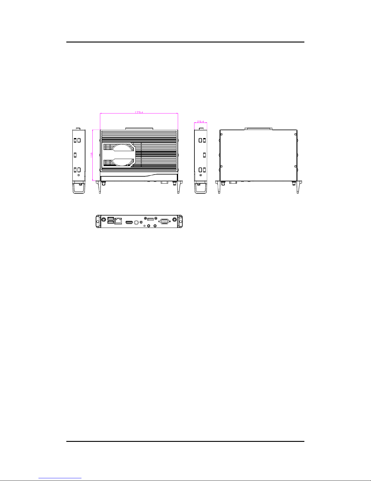
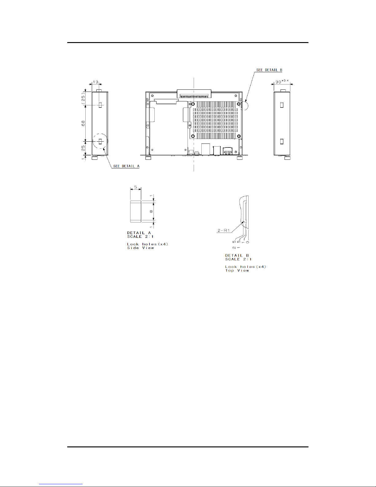
1.3.1 Dimensions
This diagram shows you dimens ions and outlines of the OPS885 series
The overall dimension of the module including the mounting frame is 200mm x 119mm x
30mm and also shows the location of the front panel screw holes as well as the security lock.
While plugging the OPS module, please make sure the heat sink side of OPS
module toward the outside. Axiomtek will be out of reasonability if there is any
damage occurred du e to it.
Introduction
4
Page 13
OPS885 User’s Manual
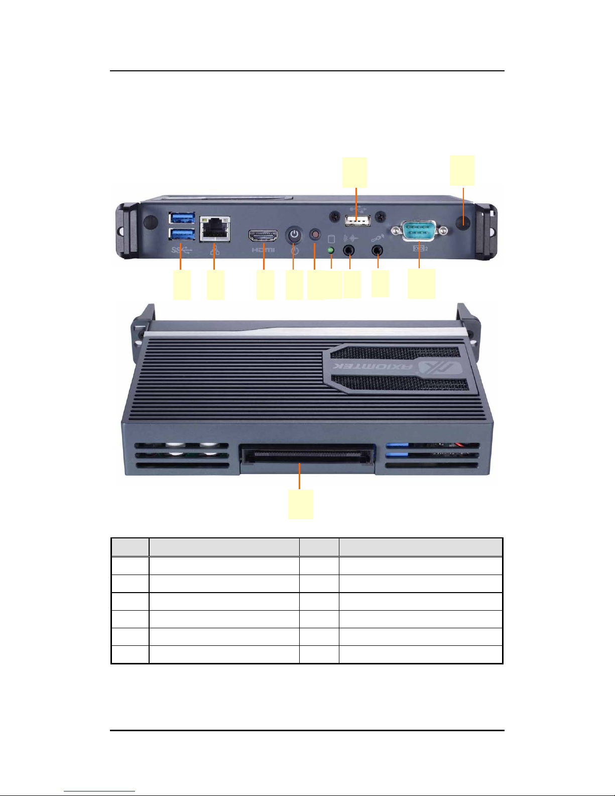
1.3.2 I/O outlet
The following figures show you th e locations of the OPS885 series I/O outlets.
No.
Connector
No.
Connector
1
JAE TX-25
7
HDD indicator
2
USB 3.0 x2
8
Audio(Line-out)
3
Ethernet
9
Audio(Mic.-in)
4
HDMI Output
10
RS-232
5
Power Switch
11
USB 2.0
6
Reset
12
Optional Antenna
1
11
12
2 3 4 5 6
7
8
9
10
Introduction
5
Page 14
OPS885 User’s Manual
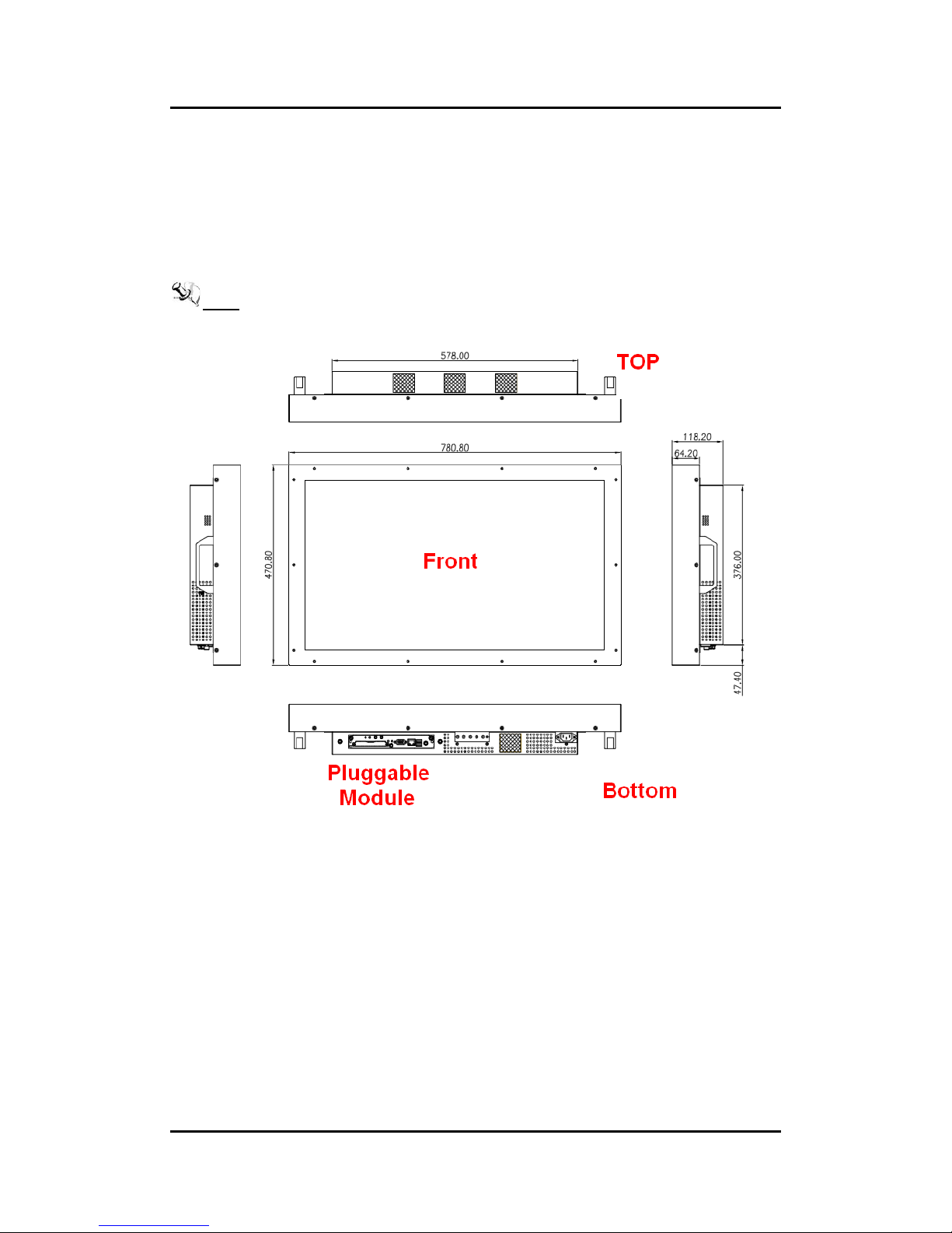
1.3.3 Mechanical Specifications
OPS885 series is docked in the reference display panel
The OPS885 Pluggable Module docked at a display panel system.
In this reference design, the module is docked and undocked in the vertical direction.
NOTE: Please contact Axiomtek for available op tion d ispl ay panel.
Introduction
6
Page 15
OPS885 User’s Manual
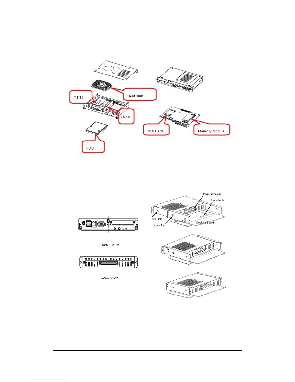
Exploded View of the Pluggable Module
The Guide Rail Mechanism for the OPS885 series Module
You can use the rails alongside of OPS885 series Module to dock and undock the plug
connector at the bac k of the module to connect with d ocking board. Ther e are two lock pins
on each side of the rail whic h serve as the lock ing mec hanism to at tach the lock holes on the
series module.
Introduction
7
Page 16
OPS885 User’s Manual
Location of Lock Hole on the Pluggable Module
*The drawing is base on Intel Open Pluggable Specification
Introduction
8
Page 17

OPS885 User’s Manual
Dimensions of the Guide Rail
Introduction
9
Page 18
OPS885 User’s Manual
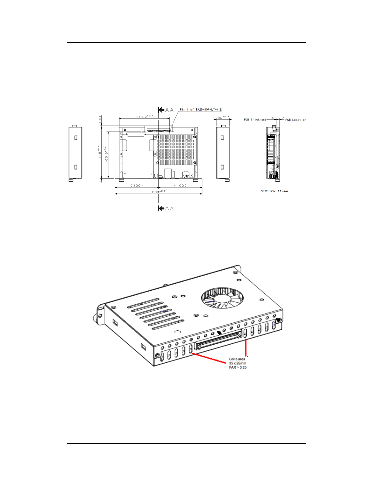
Location of JAE TX25 Plug Connector
Please refer to the f ollo win g dr a wing f or location of the J AE TX25 plug connector . P in 1 of the
connector is located at 114.8 m m fr om the edge of th e m odule, and 106. 9 mm from the inner
side of the front pa nel. For mating tolerance of TX25 p lug connector and TX24 receptacle
connector, please refer to the JAE specification
Vent Holes at the Pluggable Module Back Panel
On the OPS885 series module, it is recommended b y Intel t hat some vent holes be opened at
the back so that hot a ir can escape more easily from the module that the FAR in on both
sides of the module back panel should be greater than 0.25.
Introduction
10
Page 19
OPS885 User’s Manual
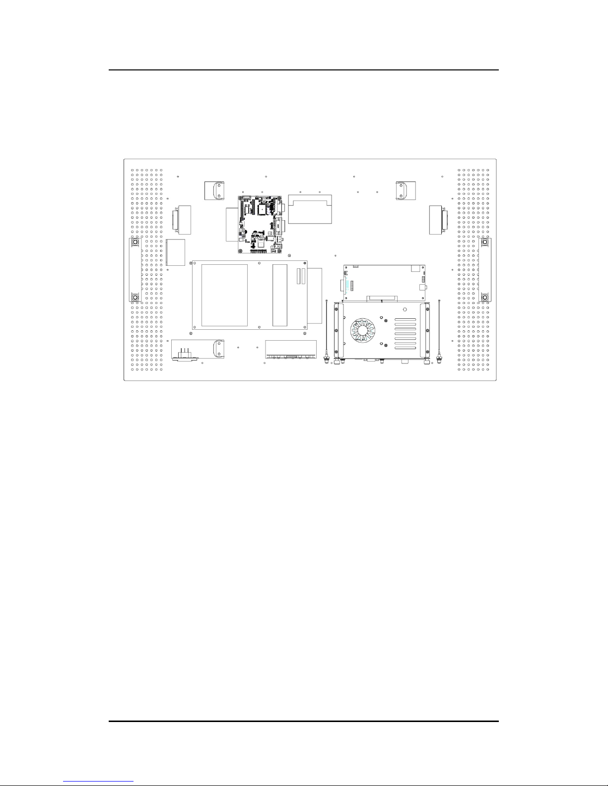
1.3.4 Reference Design
Display Panel Rear View – Internal
The digital signage OPS885 series prototype is based on a 32” display panel with
the functional blocks illustr ated. It is mainl y a 3-bo ard partitioning design consisti ng
of the plugga ble module , dock ing board an d the panel contro l board.
Introduction
11
Page 20

OPS885 User’s Manual
1.4 Package List
When you receive the OPS885 series, the bundled package should contain the
following items:
OPS885 device x 1
CD x 1
Thermal Grease (Syringe 1G)
Thermal Pad x 2
M2 x 3 screw x 2
M3 x 4 screw x 2
M4 x 10 screw x 2
If you cannot find the pack age or an y items are missing, please contact Axiomtek distributors
immediately.
Introduction
12
Page 21
OPS885 User’s Manual
CHAPTER 2
HARDWARE INSTALLATION
The OPS885 series is convenient f or your various h ardware configur ations, such as
Storage, Mem ory Modul e.
The chapter 2 will show you how to install the hardware. It inc ludes:
Storage and DRAM Installation
Pluggable Module Method
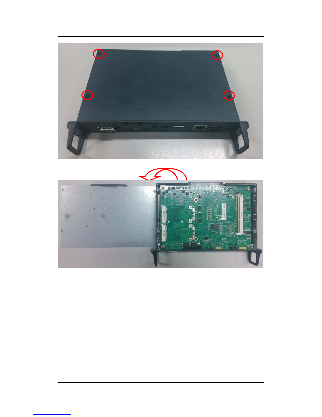
2.1 Storage, DRAM,Wireless & 3G module Installation
The OPS885 series model offers a conve nient drive bay module for user s to install
Storage, DRAM, wireless & 3G module. Please fol low the s teps:
Step 1 Turn off the system, Loosen the screws as illustrated.
Hardware Installation
13
Page 22
OPS885 User’s Manual
NOTE: Please pull out power cable of system fan while installation
Hardware Inst allation
14
Page 23
OPS885 User’s Manual
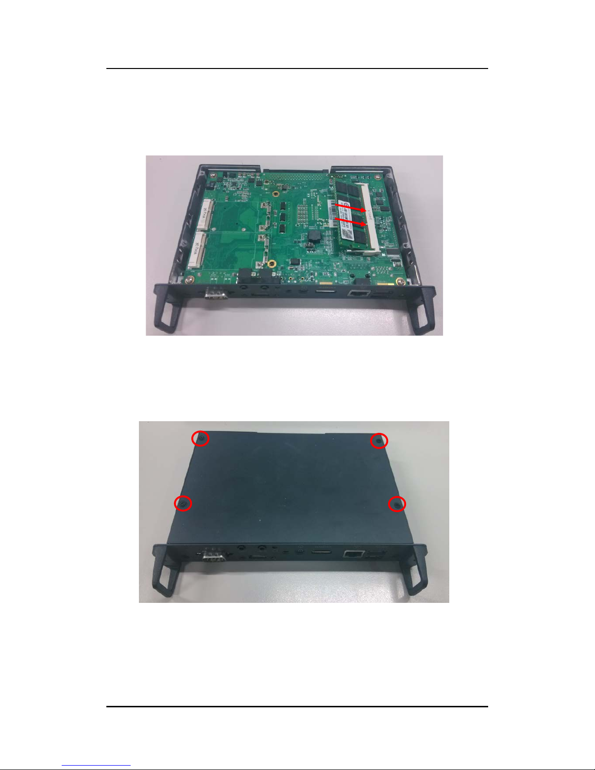
Step 2 Install DRAM
After loosen the back cover, put DRAM in the DIMM socket
Place the memory module into the socket and press it firm ly. The socket latches are
levered upwards and clipped on to the edges of the DIMM.
Step 3 Install mSATA
The OPS885 series provi des one Mini card slot for user to install mSATA. W hen
please refer to the following instructions and illustration
Loosen the screws per illustrated.
Hardware Installation
15
Page 24
OPS885 User’s Manual
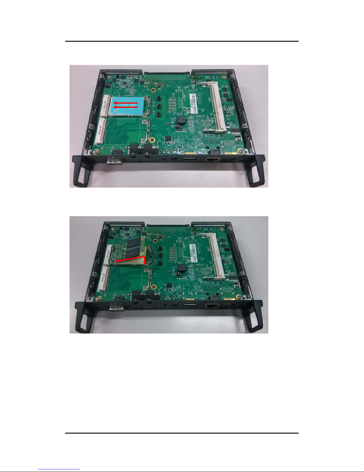
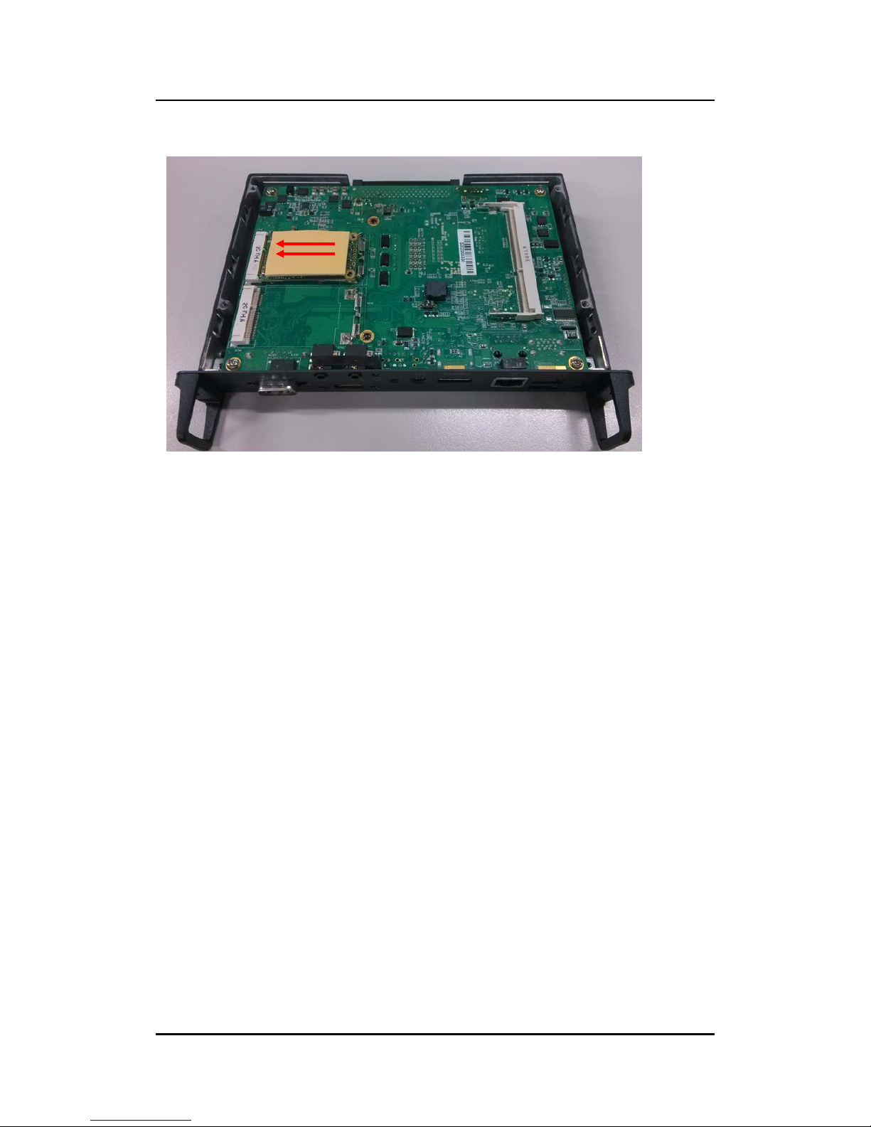
Put thermal pad on the M/B, and tear off the blue plastic sheet
Install mSATA module. Place the mSATA module into the socket and press it firmly down
until it is fully located.
Hardware Inst allation
16
Page 25
OPS885 User’s Manual
Affix another thermal pad on the mSATA
Hardware Installation
17
Page 26
OPS885 User’s Manual
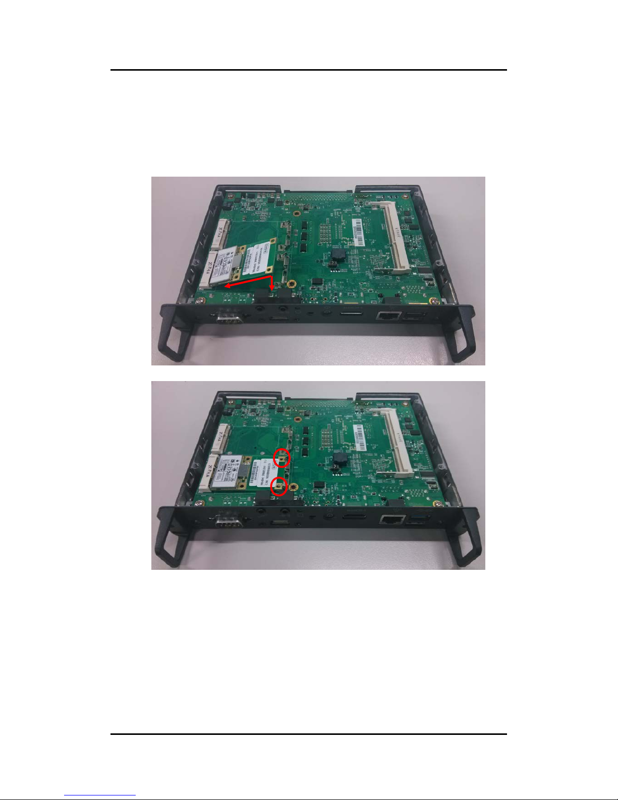
Step 4 Install Wireless Modules
The OPS885 series provides two Mini card slot for us er to install one wireless LAN
card. When install ing the wireless LAN card, refer to the following instructions and
illustration
Please refer to loosen the screws of the chassis and PCB board, place wireless
LAN and affix it firmly
Hardware Inst allation
18
Page 27
OPS885 User’s Manual
Please loosen the screws of the chass is and PCB board. Turn the PCB board per
illustrated
Find the Antenna cable and connec t it wirel es s LAN card.
Screw the antenna c onnector at expansion I/O side a nd Install the antenna on the
wireless LAN card
The wireless Module with one antenna application
:
Hardware Installation
19
Page 28

OPS885 User’s Manual
The wireless Module with two antennas application
:
Hardware Inst allation
20
Page 29

OPS885 User’s Manual
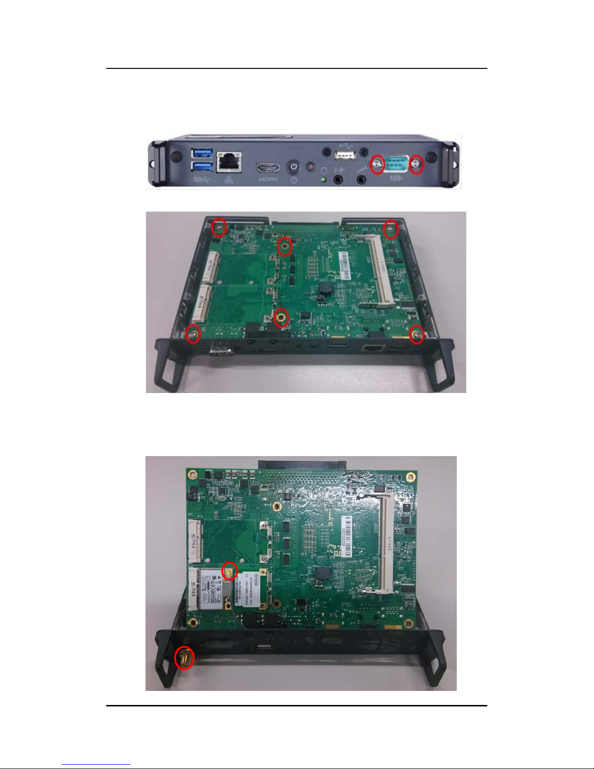
Step 5 Install 3G module
The OPS885 seri es provides one Mini card slot for us er to install one 3G module.
When installing the 3G module, refer to the following instructions and illustration
After following the step 1, please loosen the screws of the chas sis and PCB board.
Turn the PCB board per illustrated
Install SIM Card module. Place the SIM Card module into the socket and press it
firmly down until it is fully located.
Hardware Installation
21
Page 30

OPS885 User’s Manual
Install 3G module. Place the 3G module into the socket and press it firmly do wn
until it is fully located.
Affix the screws per illustrated
Hardware Inst allation
22
Page 31

OPS885 User’s Manual
NOTE: You may also install wireless LAN card at this socket.
Hardware Installation
23
Page 32

OPS885 User’s Manual
2.2 Pluggble Module Method
NOTE: Please contact Axiomtek for the available option display
Step 1 Pluggable the box into display
Caution: When plugging OPS885 into an OPS display, make sure the module’s heat
sink is facing outside of the display. Axiomtek is not responsible for any damage
caused by wrong installation
.
Step 2 Fasten the screws as illustrated
Hardware Inst allation
24
Page 33

OPS885 User’s Manual
CHAPTER 3
CONNECTORS
This chapter provides users with detailed description how to set up basic system
configuration through t he AMIBIOS8 BIOS s etup utility.
3.1 Connectors
Connectors connect this board with other parts of the system. Loose or improper
connection m ight cause problem s. Make sure all con nectors are prop erly and firmly
connected.
Here is a summ ary tabl e shows you all co nnector s on the board.
Connector
Label
JAE TX25 Connector
CN1
Mini Card Slot 1
CN3
SIM Card Slot
CN4
USB2.0 Port 9(USB Cable)
CN6
POWER BUTTON +LED
CN7
HDMI
CN8
RESET BUTTON
CN9
CPU FAN
CN12
m-SATA Slot
SCN2
Mini Card Slot 2
SCN4
Audio MIC-IN Connector
SCN5
Audio LINE-OUT Connector
SCN6
Battery 2 PIN
BAT1
ATX Auto Power On (SSW1 1&4)
SSW1
Clear CMOS (SSW1 2&3)
DDR3L Memory Slot
SDIMM1
RJ45 (I217LM)
LAN1
USB3.0/2.0 Port
USB1
COM Po rt
COM2
HDD LED
SLED3
Connectors
25
Page 34

OPS885 User’s Manual
Connectors
26
Page 35

OPS885 User’s Manual
3.1.1 JAE TX25 Connector (CN1)
Connector JAE TX 25 CN1 is f or JAE interface s upport.
Pin
Signal
Pin
Signal
Pin
Signal
Pin
Signal
1
DDP_3N
2
DDP_3P
3
GND
4
DDP_2N
5
DDP_2P
6
GND
7
DDP_1N
8
DDP_1P
9
GND
10
DDP_0N
11
DDP_0P
12
GND
13
DDP_AUXN
14
DDP_AUXP
15
DDP_HPD
16
GND
17
TMDS_CLK-
18
TMDS_CLK+
19
GND
20
TMDS0-
21
TMDS0+
22
GND
23
TMDS1-
24
TMDS1+
25
GND 26 TMDS2- 27 TMDS2+
28
GND
29
DVI_DDC_DATA
30
DVI_DDC_CLK
31
DVI_HPD
32
GND
33
+12V~+19V
34
+12V~+19V
35
+12V~+19V
36
+12V~+19V
37
+12V~+19V
38
+12V~+19V
39
+12V~+19V
40
+12V~+19V
41
RSVD
42
RSVD
43
RSVD
44
RSVD
45
RSVD
46
RSVD
47
RSVD
48
RSVD
49
SLP_S3
50
SYS_FAN
51
UART_RXD
52
UART_TXD
53
GND
54
StdA_SSRX-
55
StdA_SSRX+
56
GND
57
StdA_SSTX-
58
StdA_SSTX+
59
GND
60
USB_PN2
61
USB_PP2
62
GND
63
USB_PN1
64
USB_PP1
65
GND
66
USB_PN0
67
USB_PP0
68
GND
69
AZ_LINEOUT_L
70
AZ_LINEOUT_R
71
NC
72
PB_DET
73
PS_ON#
74
PWR_STATUS
75
GND
76
GND
77
GND
78
GND
79
GND
80
GND
Connectors
27
Page 36

OPS885 User’s Manual
3.1.2 Mini Card Slot (CN3)
Pin
Signal
Pin
Signal
Pin
Signal
1
WAKE#
2
+3.3VAUX
3
RVD1
4
GND
5
RVD2
6
+1.5V
7
CLKREQ#
8
SIM Card_Power
9
GND
10
SIM Card_I/O
11
REFCLK-
12
SIM Card_CLK
13
REFCLK+
14
SIM Card_RST-
15
GND
16
SIM Card_VPP
17
RVD3
18
GND
19
RVD4
20
+3.3VAUX
21
GND
22
PERST#
23
PERN0
24
+3.3VAUX
25
PERP0 26 GND 27 GND
28
+1.5V
29
GND
30
SMB_CLK
31
PETN0
32
SMB_DATA
33
PETP0
34
GND
35
GND
36
USB_D-
37
RVD5
38
USB_D+
39
+3.3VAUX
40
GND
41
+3.3VAUX
42
LED_WWAN#
43
RVD8
44
LED_WLAN#
45
RVD9
46
LED_WPAN#
47
RVD10
48
+1.5V
49
RVD11
50
GND
51
RVD12
52
+3.3VAUX
53
NH1
54
NH2
55
NH3
56
NH4
Connectors
28
Page 37

OPS885 User’s Manual
3.1.3 Sim Slot (CN4)
Pin Signal
1 SIM_PWR
2 SIM_RESET
3 SIM_CLK
4 NC
5 GND
6 SIM_DATA
7 SIM_I/O
8 NC
3.1.4 USB2.0 Port9 (CN6)
Pin
Signal
1
+5V
2 USB D3 USB D+
4
GND
5 GND
3.1.5 Power Button(CN7)
Pin Signal
1 PWRBTN2 PWRBTN3 GND
4 GND
5 5VSB
6 +5V
Connectors
29
Page 38

OPS885 User’s Manual
3.1.6 HDMI Connector (CN8)
The HDMI (High-Definition Multimedia Interface) is a compact digital interface which is
capable of transmitting high-definit ion video and high-resolut ion audio over a single ca ble. Its
interface is available through connector CN8.
3.1.7 Reset Button (CN9)
CN9 is the res et switch that reboots your computer instead of turning OFF the power switch. It is a
better way to reboot your system for a longer life of the system’s power supply.
Pin Signal
1 RST2 GND
3 GND
4 GND
3.1.8 CPU FAN (CN12)
Pin Signal
1 GND
2 FAN CTRL
3 VCC
Pin
Signal
Pin
Signal
19 1
18 2
1
HDMI OUT_DATA2+
2
GND
3
HDMI OUT_DATA2-
4
HDMI OUT_DATA1+
5
GND
6
HDMI OUT_DATA1-
7
HDMI OUT_DATA0+
8
GND
9
HDMI OUT_DATA0-
10
HDMI OUT Clock+
11
GND
12
HDMI OUT Clock-
13
N.C.
14
N.C.
15
HDMI OUT_SCL
16
HDMI OUT_SDA
17
GND
18
+5V
19
HDMI_HTPLG
Connectors
30
Page 39

OPS885 User’s Manual
3.1.9 mSATA Slot (SCN2
)
Pin
Signal
Pin
Signal
Pin
Signal
Pin
Signal
1
NC
2
+3.3VAUX
3
RVD1
4
GND
5
RVD2
6
+1.5V
7
CLKREQ#
8
RVD19
9
GND
10
RVD18
11
REFCLK
12
RVD16
13
REFCLK+
14
RVD15
15
GND
16
RVD14
17
RVD3
18
GND
19
RVD4
20
+3.3VAUX
21
GND
22
PERST#
23
m-SATA RXP
24
+3.3VAUX
25
m-SATA RXN 26 GND 27 GND
28
+1.5V
29
GND
30
SMB_CLK
31
m-SATA TXN
32
SMB_DATA
33
m-SATA TXP
34
GND
35
GND
36
USB_D-
37
RVD5
38
USB_D+
39
+3.3VAUX
40
GND
41
+3.3VAUX
42
NC
43
RVD8
44
NC
45
RVD9
46
NC
47
RVD10
48
+1.5V
49
RVD11
50
GND
51
RVD12
52
+3.3VAUX
53
NH1
54
NH2
55
NH3
56
NH4
Connectors
31
Page 40

OPS885 User’s Manual
3.1.10 Mini Card Slot 2 Connector(SCN4)
Pin
Signal
Pin
Signal
Pin
Signal
Pin
Signal
1
WAKE#
2
+3.3VAUX
3
RVD1
4
GND
5
RVD2
6
+1.5V
7
CLKREQ#
8
RVD19
9
GND
10
RVD18
11
REFCLK-
12
RVD16
13
REFCLK+
14
RVD15
15
GND
16
RVD14
17
RVD3
18
GND
19
RVD4
20
+3.3VAUX
21
GND
22
PERST#
23
PERN0
24
+3.3VAUX
25
PERP0 26 GND 27 GND
28
+1.5V
29
GND
30
SMB_CLK
31
PETN0
32
SMB_DATA
33
PETP0
34
GND
35
GND
36
USB_D-
37
RVD5
38
USB_D+
39
+3.3VAUX
40
GND
41
+3.3VAUX
42
LED_WWAN#
43
RVD8
44
LED_WLAN#
45
RVD9
46
LED_WPAN#
47
RVD10
49
RVD11
48
+1.5V
50
GND
51
RVD12
52
+3.3VAUX
53
NH1
54
NH2
55
NH3
56
NH4
3.1.11 Audio Mic-In Connector(SCN5)
Pin
Signal
1
GND
2
MIC_IN_R
3
GND
4
MIC_IN_L
5
MIC_DETECT
Connectors
32
Page 41

OPS885 User’s Manual
3.1.12 Audio Line-Out Connector (SCN6)
Pin Signal
1 GND
2 LINE_OUT_R
3 GND
4 LINE_OUT_L
5 LINE_OUT_DETECT
3.1.13 Battery 2 Pin (BAT1)
Pin Signal
1 +VBAT
2 GND
3.1.14 ATX Auto Power ON/ Clear CMOS (SSW1-Pin4)
AT or ATX Select ( SSW1- Pin1 & Pin4)
Description
Settings
ATX OFF (Default)
AT ON
Clear CMOS (SSW1- Pin2 & Pin3 )
Description Settings
Clear CMOS OFF (Default)
Clear CMOS ON
Connectors
33
Page 42

OPS885 User’s Manual
3.1.15 RJ45 (I217LM) (LAN1)
The RJ-45 connector L AN1 is for Ethernet. To connec t the board to 100-Base-T or
1000-Base-T hub, just plug one end of the cable into LAN1 and connect the other
end (phone jack) to a 100-Base-T hub or 10 00-Base-T hub.
Pin Signal
1
23
45
6
78
A B
1
Tx+ (Data transmission positive)
2
Tx- (Data transmission negative)
3
Rx+(Data reception positive)
4
RJ-1(For 1000 base T-Only)
5
RJ-1(For 1000 base T-Only)
6
Rx- ( Data reception negative)
7
RJ-1(For 1000 base T-Only)
8
RJ-1(For 1000 base T-Only)
A
Active LED
B
Speed LED
3.1.16 USB Port 0/1 (USB1)
Pin Signal
1 USB3_POWER
2 USB D03 USB D0+
4 GND
5 USB3_SSRX06 USB3_SSRX0+
7 GND
8 USB3_ SSTX0-
9 USB3_ SSTX0+
10 USB3_POWER
11 USB D112 USB D1+
13 GND
14 USB3_SSRX115 USB3_SSRX1+
16 GND
17 USB3_ SSTX118 USB3_ SSTX1+
Connectors
34
Page 43

OPS885 User’s Manual
3.1.17 COM Port (COM2)
The COM Port co nnector is a standard DB-9 c onnector. The pin as signment of RS232 is list ed on t he followi ng table
Pin Signal
1 DCD, Data carrier detect
2 RXD, Receive data
3 TXD, Transmit data
4 DTR, Data terminal ready
5 GND, ground
6 DSR, Data set ready
7 RTS, Request to send
8 CTS, Clear to send
9 RI, Ring indicator
3.1.18 Power LED
The Power LED lights up when the system is powered ON.
3.1.19 HDD Activity LED
This connection is link ed to hard drive activity LED on the contr ol panel. LED flashes when
HDD is being accessed
Connectors
35
Page 44

OPS885 User’s Manual
This page is intentionall y left blank.
Connectors
36
Page 45

OPS885 User’s Manual
CHAPTER 4
DRIVERS INSTALLATION
4.1 System
OPS885 series supports Window 7. To facilitate the installation of system driver, please
carefully read the instructions in this chapter before start installing.
Insert Intel Express Installer Driver CD and select the “\Driver\”.
Select your operating system driver to install.
Select all files and follow the installing procedure.
NOTE: For latest system driver for installation, you may visit Axiomtek website at
www.axiomtek.com
Drivers Installation
37
Page 46

OPS885 User’s Manual
This page is intentionall y left blank.
Drivers Installation
38
Page 47

OPS885 User’s Manual
CHAPTER 5
AMI BIOS SETUP UTILITY
This chapter provides users with detailed description how to set up basic system
configuration through t he AMIB IOS8 BIO S setup utility.
5.1 Starting
To enter the set up scree ns, foll ow the st eps belo w:
Turn on the computer and press the <Del> key immediately.
After you press the <Del> key, the main BIOS setup menu displays. You can
access the other setup screens from the main BIOS setup menu, such as the
Chipset and Power menus.
5.2 Navigation Keys
The BIOS set up/utility uses a key-based navig ation system cal led hot keys. M ost of
the BIOS setup utility hot keys can b e used at any time dur ing the setup navig ation
process.
These keys inc lude <F1>, <F2>, <Enter>, <ESC>, <Arrow> keys, and so on.
NOTE: Some of navigation keys differ from one screen to another.
Hot Key Description
Left/Right
The Left <Arrow> keys allow you to select a setup screen.
Up/Down
The Up and Down <Arrow> key
s allow you to select a setup screen or
sub-screen.
+− Plus/Minus
The Plus and Minus <Arrow> keys allow you to change the field value
of a particular setup item.
Tab
The <Tab> key allows you to select setup fields.
F1
The <F1> key allows you to display the General Help screen.
F2
The <F2> key allows you to Load Previous Values.
F3
The <F3> key allows you to Load Optimized Defaults.
F4
The <F4> key allows you to save any changes you have made and
exit Setup. Press the <F4> key to save your changes.
Esc
The <Esc> key allows you to discard any changes you have made and
exit the Setup. Press the
<Esc> key to exit the setup without saving your changes.
Enter
The <Enter> key allows you to display or change the setup option
listed for a particular setup i
tem. The <Enter> key can also allow you
to display the setup sub- screens.
AMI BIOS Setup Utility
39
Page 48

OPS885 User’s Manual
5.3 Main Menu
When you first e nter the Setu p Utility, you will enter the Main setup scr een. You can
always return to the Main setup screen by selecting the Main tab. There are two
Main Setup options. They are described in this section. The Main BIOS Setup
screen is shown bel ow.
Syst em Date/T ime
Use this opti on to change the system date and time. Highlight System Date or
System Time using the <Arrow> keys. Enter new values through the keyboard.
Press the <Tab> key or the <Enter> keys to move between fields. The date
must be entere d in MM/ DD/YY for mat. The t ime is entered in HH:M M:SS f ormat.
AMI BIOS Setup Utility
40
Page 49

OPS885 User’s Manual
5.4 Advanced Menu
Launch PXE OpROM
Use this item to enable or disable the Boot ROM functi on of the onboard LAN chip
when the s ystem boots up.
The Advanced menu also allows users to set configuration of the CPU and other
system devices . You ca n select a ny of the items i n the left frame of th e screen t o go
to the sub menus :
ACPI Settings
S5 RTC Wake Set tings
Trusted Computing
CPU Configuration
SATA Configuration
PCH-FW Configuration
USB Configuration
F81801 Super IO Configuration
F81801 H/W Monitor
For items marked with “”, please press <Enter> for more options.
AMI BIOS Setup Utility
41
Page 50

OPS885 User’s Manual
ACPI Settings
You can use this screen to select options for the ACPI Configuration, and change
the value of the s elected option. A descript ion of the selected item app ears on the
right side of t he screen.
ACPI Sleep State
Allow you to select the Advanced Configuration and Power Interface (ACPI)
state to be used for system suspend. Here are th e options for your sel ection, S3
(Suspend to R AM)
AMI BIOS Setup Utility
42
Page 51

OPS885 User’s Manual
S5 RTC Wake Settings
Enable or dis able system wake on alarm event. When enabled, System wi ll wake on
the hr:min::sec specif ied
AMI BIOS Setup Utility
43
Page 52

OPS885 User’s Manual
Trusted Computing
Enables or disables BIOS support for security device. O.S. will not show Security
Device. TCG EFI protoc ol and INT1A int erface will no t be available.
TCG EFI protocol and IN T1A interfac e will not be avail able.
AMI BIOS Setup Utility
44
Page 53

OPS885 User’s Manual
CPU Configuration
This screen shows the CPU Configuration, and you can change the value of the
selected option.
Hyper-threading
This feature can enable /disable Intel Hyper-Threading technology
In tel Virtualization Technology
Allows a hardware platform to run multiple operating systems separately and
simultaneous ly, enabl ing one s ystem to virtual ly functio n as sev eral systems.
EIST
This feature can enable /disable Enhanc ed Inte l speed Step T echnolog y (EIST
EIST (Enhanced Intel Speed Step Technology) allows the system to
automatically adjust proces sor voltage and core frequenc y in an effort to reduc e
power c onsumpti on and heat diss ipation
AMI BIOS Setup Utility
45
Page 54

OPS885 User’s Manual
SATA Configuration
You can use this screen to select options for the SATA Configuration, and change
the value of the s elected option. A description of the sel ected item appears on the
right side of t he screen.
Serial-ATA Controller(S)
Use this item to enable or disable the integrated SATA controllers. (Default:
Enabled
SATA Mode Selection
Use this item to ch oose the SATA o peratio n mode. Here are the op tions for your
selection, IDE Mode, A HCI Mode.
S ATA Controller Speed
Use this item to chang e the SAT A transfer rate
Serial-ATA Port
Enable or Disable SATA Port
AMI BIOS Setup Utility
46
Page 55

OPS885 User’s Manual
PCH-FW Configuration
You can use this screen to c onfirm ME Firm ware vers ion.
AMI BIOS Setup Utility
47
Page 56

OPS885 User’s Manual
USB Configuration
You can use this s creen to select options for t he USB Conf iguration, a nd change th e
value of the se lected option. A des cription of the selected item appe ars on the right
side of the sc reen.
Legacy USB Support
This is for supporting U SB device under legac y OS such DOS, when c hoosing
AUTO”, the system will automaticall y detect any USB device is plugged into the
computer and enable USB legacy mode when a USB device plugged and
disable USB leg acy m ode when no USB d evice is p lugged.
X HCI Mode
Mode of operat ion of XH CI contr oller
AMI BIOS Setup Utility
48
Page 57

OPS885 User’s Manual
USB Ports Per-Port Disable
Control each of t he US B ports (0 ~13) ports
F81801 Super IO Configuration
Set Parameter s of Ser ial Port (COM 1 UART)
AMI BIOS Setup Utility
49
Page 58

OPS885 User’s Manual
F81801 H/W Monitor
This screen shows the Hardware Health Configuration, And Enable or disables
smart fan.
AMI BIOS Setup Utility
50
Page 59

OPS885 User’s Manual
5.5 Chipset Menu
The Chipset m enu allows u sers to c hange the adva nced chipse t settings. You can selec t any
of the items in the left frame of the screen to go to the sub menus:
PCH–IO Configuration
System Agent(SA) Configuration
AMI BIOS Setup Utility
51
Page 60

OPS885 User’s Manual
PCH–IO Configuration
PCH Azali a C onfigur ation settings
PCH Azalia Configuration
PCH Azalia Conf igurat ion settin gs.
PCH L AN Controller
Enable or disa ble onbo ard NIC
Wake on LAN
Use this item to en able or disab le integrated LAN to wak the s ystem . (The Wake
On LAN cannot be disabl e if ME is on at Sx satat e).
AMI BIOS Setup Utility
52
Page 61

OPS885 User’s Manual
System Agent(SA) Configuration
CPU SA Audio Device (BO :D3:F0)
Enable or disable CP U SA audio devic e
Graphics Configuration
Config graphic s settin gs.
M emory Info rmation
Memory configur ation parameter s
AMI BIOS Setup Utility
53
Page 62

OPS885 User’s Manual
Primary IGFX Boot Display
Select the video devic e which will be activated during POST. This has no eff ect
if external gr aphics presents.Sec ondary boot displa y selection will a ppear base
on your select ion.
DVMT Pre-Allocated
Pre-allocated m emory is the sm all amount of system m emory made avai lable at
boot time b y the system BIO S for video. Pr e-allocated memory is also known as
locked memor y. This is because it is "locked" for vide o use only and as suc h, is
invisible and unab le to be us ed b y the operat ing system .
AMI BIOS Setup Utility
54
Page 63

OPS885 User’s Manual
Memory Information
Memory configur ation parameter s
M ax TOLUD
This item allows you to s et Maxim um Value of TOLUD
AMI BIOS Setup Utility
55
Page 64

OPS885 User’s Manual
5.6 Boot Menu
The Boot m enu allows users to cha nge boot options of t he system. You can select
any of the item s in the left f rame of th e screen to go to the sub m enus:
(images requires to upd ate)
Setup Prompt Timeout
Boot up Num Lock State
Quiet Boot
Launch PXE OpROM policy
Boot Option #1
Boot Option #2
Hard Drive BBS Priorities
Setup Prompt Timeout
Set the Tim eout for wa it press key to enter Setup Me nu
Boot up Mum Lock State
Use this item to select the power -on state for the Mum Lock . The d efault sett ing
is on.
Quiet Boot
Use this item to enabl e or disab le the Qu ite Boot state. The default setting is
disabling.
AMI BIOS Setup Utility
56
Page 65

OPS885 User’s Manual
Launch PXE OpROM policy
Controls the execution of UEFI and Legacy PXE OpROM
Boot Option #1
Sets the system boot order
Boot Option #2
Sets the system boot order
Hard Drive BBS Priorities
Set the order of the lega cy devices in this group.
5.7 Security Menu
The Securit y menu allo ws users t o chang e the sec urity sett ings for the s ystem.
Admin istrato r Password
This item indicates whether an administrator password has been set. If the
password has been inst alled, Instal led displa ys. If not, Not Instal led displays.
User Password
This item indicates whether a us er password has been set. If the password has been
installed, Installed displays. If not, Not Installed displays.
AMI BIOS Setup Utility
57
Page 66

OPS885 User’s Manual
5.8 Save & Exit Menu
The Save & Exit menu allows users to load your system configuration with optimal
or failsafe defau lt values.
Save Changes and Exit
When you hav e completed the s ystem configuration c hanges, select th is option
to leave Setup and return t o Main M enu. Select Save Changes an d Exit from the
Save & Exit menu and pr ess <Enter> . Select yes to save chang es and exit.
Discard Changes and Exit
Select this option to quit Setup without making any permanent changes to the
system configur ation and retur n to Main Men u. Select Discard Ch anges and Exit
from the Save & Exit menu and press <Enter>. Select Yes to discard changes
and exit.
Save Changes and Reset
When you hav e completed the s ystem configuration c hanges, select th is option
to leave Setup and reboot the computer so the new system configuration
parameters can take effect. Select Save Changes and Reset from the Save &
Exit menu and press <E nter>. Select Yes to save chan ges and reset.
AMI BIOS Setup Utility
58
Page 67

OPS885 User’s Manual
Discard Changes and Reset
Select this option to quit Setup without making any permanent changes to the
system configuration and reboot the computer. Select Discard Changes and
Reset from the Save & Exit menu and press <Enter>. Select Yes to discard
changes and reset.
Save Changes and Reset
When you have com pleted the system configuration chang es, select this opti on
to save changes. Select Save Changes from the Save & Exit menu and press
<Enter>. Select Yes t o save c hanges.
Discard Changes and Reset
Select this option to quit Setup without making any permanent changes to the
system configuration. Select Discard Changes from the Save & Exit menu and
press <Enter>. Sel ect Yes to discar d changes .
Save Changes
When you hav e completed the s ystem configuration c hanges, select th is option
to save changes. Select Save Changes from the Save & Exit menu and press
<Enter>. Selec t Yes to s ave cha nges.
Discard Changes
Select this option to quit Setup without making any permanent changes to the
system configuration. Select Discard Changes from the Save & Exit menu and
press <Enter >. Select Yes to dis card ch anges.
Restore Defaults
It automatical ly sets a ll Setup options to a compl ete set of default set tings when
you select this o ption. The Optimal settings ar e designed for maxim um system
performance, but may not work best for all com puter applications . In particular,
do not use the Optimal Setup options if your com puter is experiencing system
configuration problems. Se lect Restore Defaults f rom the save & Exit menu and
press <Enter>.
Save as User Defaults
Select this option to save system configuration changes done so far as User
Defaults. Select Save as User Defaults from the Save & Exit menu and press
<Enter>.
Restore User Defaults
It automatica lly sets all Setup options to a complete set of User Defau lts when
you select this option. Select Restore Us er Defaults from the Save & Exit menu
and press <Ent er>.
AMI BIOS Setup Utility
59
Page 68

OPS885 User’s Manual
This page is intentionall y left blank.
AMI BIOS Setup Utility
60
Page 69

OPS885 User’s Manual
APPENDIX A
REFERENCE DOCUMENTS
Reference Documents
61
Page 70

OPS885 User’s Manual
This page is intentionall y left blank.
Reference Documents
62
Page 71

OPS885 User’s Manual
APPENDIX B
Trusted Platf orm M odule (TPM) Installation
Trusted Platform Module Installation
The OPS885 series model offers Trusted Platform Module(TPM) feature. Please
follow the steps:
Step 1 Before instal ling the TPM driver, please restart the computer and pr ess the <Del>
key immediately. After you press the <Del> key, you may access to the main BIOS setup
menu displays. Please go to the BIOS setting
Go to Advanced menu and enable Securit y Devic e Support
Trusted Platform Module (TPM) Installation
63
Page 72

OPS885 User’s Manual
Step 2 Please press <F4> to save the c hange and <ESC> to exit the BIOS set up
menu
Trusted Platform Module (TPM) Installation
64
Page 73

OPS885 User’s Manual
Step 3 Press the <Del> key immediately once again and enter main BIOS setup
menu displa ys, go to Ad vanced m enu and enable T PM state
And then press <F4> to save the change and exit the BIOS set up menu, you are
able to enable T rusted Platform Module f eature.
Trusted Platform Module (TPM) Installation
65
Page 74

OPS885 User’s Manual
Step 4 After accessing to OS, go to C omputer session of the S tart and right-click
mouse and chos e Proper ties
Step 5 After ent ering the Properties session, chose the Unkno wn device and right
click and chose Update Driver Software
Trusted Platform Module (TPM) Installation
66
Page 75

OPS885 User’s Manual
Step 6 Chose “Browse for driver software on your computer” and find the driver
and press OK for loading
Step 7 After choosing, press Next to finish the update
Trusted Platform Module (TPM) Installation
67
Page 76

OPS885 User’s Manual
And the n the T PM driver is upda ted succes sfull y.
Step 8 While you insta lled TPM driver s uccessfully, you can be able to i nstall TPM
application.program.
Trusted Platform Module (TPM) Installation
68
Page 77

OPS885 User’s Manual
APPENDIX C
WATCHDOG TIMER
Watchdog Tim er Settin g
After the system stops working for a while, it can be auto-reset by the Watchdog
Timer. The i ntegrated Watchdog Timer can be set up in the system reset mode by
program.
Using the Watchdog Function S
tart
1.Enable conf iguration( Followi ng is exam ple to enable c onfigura tion by usin g debug)
-O 2E 87
-O 2E 87
2. Select Logic devic e:
-O 2E 07
-O 2F 07
3. WDT D evice Enab le
-O 2E 30
-O 2F 01
4. Activat e W DT :
-O 2 E F0
-O 2F 80
5. Set base timer:
-O 2 E F6
-O 2F 0A Set Res et Tim e (Ex. A: 10 Sec)
6. Se t tim er unit
-O 2 E F5
-O 2F 71(1: Sec ; 9: Minute)
Watchdog Timer
69
Page 78

OPS885 User’s Manual
This page is intentionall y left blank.
Watchdog Timer
70
Page 79

OPS885 User’s Manual
APPENDIX D
iAMT SETTINGS
The Intel® Active Management Technology (Intel® iAMT) has decreased a major
barrier to IT efficienc y that uses bui lt-in pla tform capabilities and popular third-party
management an d security applicat ions to allow IT a bett er discovering, h ealing, and
protection the ir network ed com puting as sets.
In order to utilize I ntel iAMT you m ust enter the ME BIO S (CTRL + P dur ing system
startup), change the ME BIOS password, and then select “Intel
®
iAMT” as the
manageabilit y feature .
C.1 Entering M EBx
1. Yo u must go to BIOS TO star t iAMT f unction.
2. Exit from BIOS after starting iAMT, and press Ctrl+P to enter MEBx Setting.
• It is better to press Ctrl+P before the screen popping out.
iAMT Settings
71
Page 80

OPS885 User’s Manual
C.2 Set & Change Pass word
You will be asked to set a password when first log in. The default password is
‘admin’.
You will be asked to change the password before setting ME
Change
iAMT Settings
72
Page 81

OPS885 User’s Manual
You must confirm your new password while revising. (as Remark 1)
The new password must contain:(example: !!11qqQQ) (default value)Eight
characters
One upper case
One lower case
One number
One special symbol, such as !
、
$ or ; ,(、 " , excepted)
Underline ( _ ) and space are valid characters for password, but they won’t make
higher complex ity.
C.3 Intel® iAMT Settin gs
Select Intel
®
iAMT Configuration and pr ess <EN TER>.
iAMT Settings
73
Page 82

OPS885 User’s Manual
1 Key in the Host Name. If Intel
®
iAMT set to ‘DHCP‘, the Host name must be
identical to t he operat ing system mechan ic.
(3-1)
2 Select TCP/IP to get into Network interface, and set it to ‘ENABLED’; into
DHCP Mode, and set it to ‘DISABLED’ (as Rem ark 2) ; into Domain na me, and set
the Intel Mana gement Engine dom ain nam e, suc h as ‘AMT.intel.com’.
(3-2)
iAMT Settings
74
Page 83

OPS885 User’s Manual
You ca n mak e the follow ing sett ings:
Remark 2 DHCP Mode ‘DISABLED‘: if DHC P Mode is disable d,
IP address
Subnet mask
iAMT Settings
75
Page 84

OPS885 User’s Manual
Preferred DNS address
Alternate DNS address
iAMT Settings
76
Page 85

OPS885 User’s Manual
Domain name
4.Exit from MEBx after completin g the iA MT setti ngs.
C.4 i AMT Web Con sole
1.From a web browser, please type http://(IP ADDRESS):16992, which connects to
iAMT W eb.
Example: http://10.1.40.214:16992
iAMT Settings
77
Page 86

OPS885 User’s Manual
2 To log on, you wil l be required to t ype in username and pas sword for access to
the Web. USER : admin ( default value)
PASS: (ME Bx pass word)
3. Enter the iAMT Web.
4 Click Remote C ontrol, a nd select c omm ands on the r ight si de.
5. When you have finish ed using the iAMT W eb console, c lose the Web bro wser
iAMT Settings
78
Page 87

OPS885 User’s Manual
APPENDIX E
INTEL
®
R APID STORAGE TECHNOLOGY
NOTE: This feature requires that the SATA controller be set to RAID mode via the
system BIOS.
Intel ® Smart Resp onse Technology is an Intel ® Rapid Storage Technolog y (RST)
caching feature that improves computer system performance. It allows a user to
configure com puter systems with an SSD used as cache memory betwe en the hard
disk drive and s ystem memory. This pro vides the advantage of hav ing a hard disk
drive (or a RA ID volume) for maxim um storage c apacit y while deliver ing an SSD -like
overall system performance experience. Intel ® Smart Response Technology
caching is implem ented as a single drive let ter solution; no additiona l drive letter is
require for the SSD de vice used as cache .
System Requi rements:
For a system to sup port Intel Sm art Respons e Technolog y it must have t he followi ng:
1. Intel ®QM87 Express C hipset-base d desktop boar d
2. S ystem BIO S with S ATA m ode set to R AID
3. Intel R apid Stor age Tech nolog y software 10.5 ver sion rel ease or l ater
4. Si ngle Hard Disk D rive(HDD) or mult iple HDD ’s in a sin gle R AID vo lume.
5. So lid State Driv e(SSD) with a minim um capacit y of 18.6G B
6. Operating system: Microsof t ware Window’s* Vista 3 2-bit Edition and 64-bit
Edition, Micros oft W indows* 7 3 2-bit Edition an d 64-bit
System Requi rements:
Configuration SATA Mode in BIOS Setup
1. Press the F2 during boot up to enter the BIOS set up menu
2. Go to Configur ation > SATA Dr ives
3. Select the s etting f or Chipset SATA Mo de and c hange th e value to RAID.
4. Press the F10 k ey to sa ve settin gs and res tart th e system .
System Requi rements:
5. You may now begin ins tallati on of the operat ing system on the HDD(or R AID
volume)
6. Install all r equired d evice dr ivers
7. Install the Intel Rapid S torage T echnolog y soft ware vers ion 10.5 or later
Enable Intel Sm art Resp onse T echnolog y
NOTE: The Intel RST software denotes Intel Smart Response Technology as
Accelerate
Intel
®
Rapid Storage Technology
79
Page 88

OPS885 User’s Manual
8. Run the Inte l RST sof tware thought the ALL Programs m enu or the tas k bar ic on.
9. Click “Enable acce leration” either under “Status” or “Accelerate”
10. Select the SSD to be us ed as a c ache de vice.
11. Select the s ize from the SSD to be al located for the c ache mem ory.
NOTE: Any remaining space on the SSD may be used for data storage using the
simple data single-disk RAI D 0 volumes that is automatically created.
12. Select the HDD (or RAID v olume) to be accel erated. It is h ighl y recomm ended
to accelerate t he syst em volum e or system disk for maximum performance.
13. Select the ac celerat ion m ode, and the n click “OK”. By default, En hanced mode
is selecte d.
NOTE: Enhanced mode (default) Acceleration optimized for data protection.
Intel
®
Rapid Storage Technology
80
Page 89

OPS885 User’s Manual
Maximized mode: Accel eration optim ized for input /output perform ance.
14. The page refres hes an d reports the ne w acceler ation conf igurat ion in the
Acceleration View.
15. Congratulations ! Your s ystem is now suc cessf ully configur ed with the Inte l Sm art
Response Techn ology!
For m ore infor mation on Intel Sm art Resp onse Te chnolog y, please visit:
http://www.intel.com/p/en_US/support/highlights/chpsts/imsm
Remark: Intel® Rapid Start Techno logy requir es an appropriat e processo r be
installed in the platform . See proces sor co llateral for further details .
Intel
®
Rapid Storage Technology
81
Page 90

OPS885 User’s Manual
This page is intentionall y left blank.
Intel
®
Rapid Storage Technology
82
 Loading...