

Page 1

NA-1301
Hardware Installation Guide
For service person only
Page 2

NA-1301 Network Appliance Server Hardware Installation Guide
Disclaimers
The information in this manual has been carefully checked and is believed to be accurate. AXIOMTEK
Co., Ltd. assumes no responsibility for any infringements of patents or other rights of third parties, which
may result from its use.
AXIOMTEK assumes no responsibility for any inaccuracies that may be contained in this document.
AXIOMTEK makes no commitment to update or to keep current the information contained in this
manual.
AXIOMTEK reserves the right to make improvements to this document and/or product at any time and
without notice.
No part of this document may be reproduced, stored in a retrieval system, or transmitted, in any form or
by any means, electronic, mechanical, photocopying, recording, or otherwise, without the prior written
permission of AXIOMTEK Co., Ltd.
Co pyright 2004 by AXIOMTEK Co., Ltd.
All rights reserved.
Version A1 September 2004
Printed in Taiwan
ii
Page 3

NA-1301 Network Appliance Server Hardware Installation Guide
Safety Approvals
CE Marking
FCC Class A
FCC Compliance
This equipment has been tested and complies with the limits for a Class A digital device, pursuant to
Part 15 of the FCC Rules. These limits are designed to provide reasonable protection against harmful
interference in a residential installation. If not installed and used in accordance with proper instructions,
this equipment might generate or radiate radio frequency energy and cause harmful interference to
radio communications. However, there is no guarantee that interference will not occur in a particular
installation. If this equipment does cause harmful interference to radio or television reception, which can
be determined by turning the equipment off and on, the user is encouraged to try to correct the
interference by one or more of the following measurers:
Reorient or relocate the receiving antenna.
Increase the separation between the equipment and receiver.
Connect the equipment into an outlet on a circuit different from that to which the receiver is connected.
Consult the dealer or an experienced radio/TV technician for help.
Shielded interface cables must be used in order to comply with emission limits.
iii
Page 4

NA-1301 Network Appliance Server Hardware Installation Guide
Safety Precautions
Before getting started, read the following im portant cautions.
1. Be sure to ground yourself to prevent static charge when installing the internal components. Use a
grounding wrist strap and place all electronic components in any static-shielded devices. Most
electronic components are sensitive to static electrical charge.
2. Disconnect the power cords from the NA-1301 Network Appliance Platform before making any
installation. Be sure both the system and the external devices are turned OFF. Sudden surge of
power could ruin sensitive components. Make sure the NA-1301 Network Appliance Platform is
properly grounded.
3. Do not open the system’s top cover. If opening the cover for maintenance is a must, only a trained
technician is allowed to do so. Integrated circuits on computer boards are sensitive to static
electricity. To avoid damaging chips from electrostatic discharge, observe the following
precautions:
Before handling a board or integrated circuit, touch an unpainted portion of the system unit
chassis for a few seconds. This will help to discharge any static electricity on your body.
When handling boards and components, wear a wrist-grounding strap, available from most
electronic component stores.
Trademarks Acknowledgments
AXIOMTEK is a tradem ark of AX IOMTEK Co., Ltd.
Other brand names and tradem arks are the properties of their respective owners.
iv
Page 5

NA-1301 Network Appliance Server Hardware Installation Guide
Table of Contents
Chapter 1 Introduction -------------------------------------------------------- --1
1.1 General Description ………………………………………1
1.2 Standard Features ……………………………………….. 2
1.3 Systems Specifications ………………………………… 3
1.4 Dimensions ………………………………………………… 6
1.5 Front Panel Outlets ……………………………………… 7
1.6 Rear Panel Outlets …… ………………………… ………. 8
1.7 Indications of Front Pa nel …………………… ………... 9
Chapter 2 Jumper and Connectors ------------------------------10
2.1 System Layout …………………………………… ……10
2.1.1 Mother Bo ard La yout ……………… …… 11
2.1.1.1 Jumper Setting …… …………………… 12
2.1.1.1.1 COM2 RS232/422/425 Setting 12
2.1.1.1.2 CMOS Clear Jumper …… 12
2.1.1.1.3 Watchdong T rigger Mode Setting .. 12
2.1.1.1.4 PICMG BUS Mode and Frequency
Setting ………………………………..12
2.1.1.2 Connectors …………………………… 14
2.1.2 Backplane La yout …………………… …… 15
Chapter 3 Installation Procedures ------------------------------- 18
3.1 Pre installation Checklist …………………………….. 18
3.2 Sett ing up th e appl iance … ……………… ………… . 19
3.2.1 Removing and Replacing the top cover . 19
3.2.2 Installing a Microprocessor (C PU) …….. 21
3.3 CPU cooler installation ……………… …………….. . 21
3.4 Insta lling a memory m odule (DIM M) …………… ….. 25
3.5 Installing a DM A/66/100 hard d rive ……… …… ….. 25
3.6 Insta lling displa y interface … …………………… …... 26
3.6.1 CRT interf ace contr oller ………………. . 26
3.6.2 Features ………………………………….. 26
3.6.3 VGA Connectors ………… ………………. . 26
3.7 Installing serial port interf ace ……………… .......…26
3.7.1 Serial port IRQ selection……………… ….27
3.8 Installing keyboard and PS/2 mou se controller … 27
3.9 Installing USB controller (Optional) ……………. … 28
3.10 Installing ATX SB5V Power Controlle r ……........... 28
3.11 Installing ATX 12V CPU Power Contro ller … ....... 28
3.12 Insta lling and Program LCD modu le …………. ...... 29
Chapter 4 Award BIOS Utility --------------------------------------32
4.1 BIOS Installation …………...................................... 32
4.2 BIOS setup …………............................................... 32
4.3 Standard CMOS Setup ………………………………… 32
4.4 Advanced BIOS Features …… ……....................... 35
4.5 Advanced Chipset Features ………….................. 38
4.6 Integrated Peripheral …………. ........................... 40
4.7 Power Management Setup …………. ...................... 42
4.8 PNP/ PCI Configuration …………. ....................... 44
4.9 PC Health Status …………................................... 45
4.10 Frequence / Volt age Control ………….................... 46
4.11 Load Optimized Default ……. ................................ 46
Appendix A Warning--------------------------------------------------49
Table of Contents
v
Page 6
NA-1301 Network Appliance Server Hardware Installation Guide
C h a p t e r 1
Introduction
This chapter contains the general information and the detailed specifications of the NA-1301 Network
Appliance server. Chapter 1 includes the following sections:
General Description Mechanical Dimensions
Features I/O Outlets
System Specifications
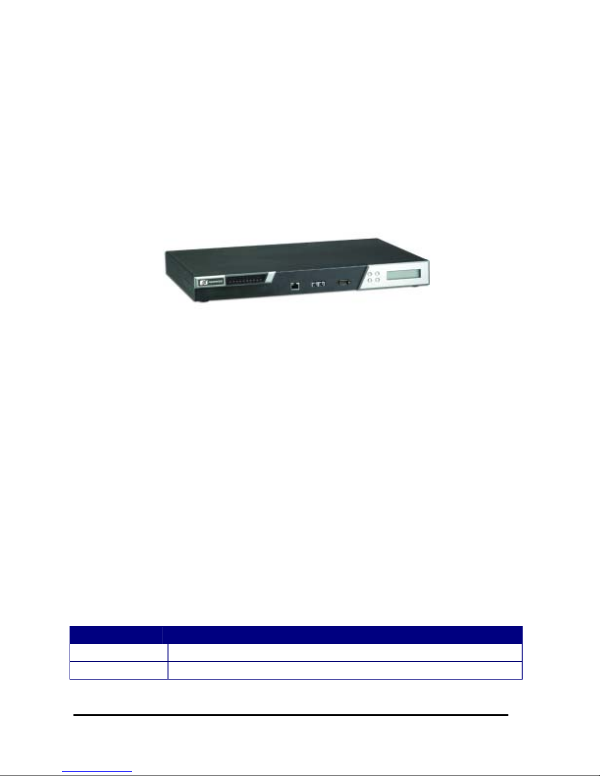
1.1 General Description
The NA-1301 server is designed for network software solution providers those have data secure, voice
over IP, video streaming, network bandwidth controller and another networking appliance requirements
across this stable and reliable multiple LAN device.
It is a reliable and affordable, 1U- he ight uni t that r eq uir es only power and network connecti ons f or s etup.
There can be deployed up to three LAN ports combinations for customer selection in the maximum for
application.
The three LAN ports can be deployed to two kinds of combinations,
One is three gigabit copper connections, other one is two gigabit fiber connectors and one gigabit
copper connections.
NA-1301 has pretty good enclosure management interface to be implemented in the factory default. It
can support P.O.S.T (Power on Self Test) feature through hyper-terminal by console port. LCD module
function is available for customer coding also.
The encryption / decryption VPN co-processor security board is enhancement for network security
process performance. It can be deployed by a PCI 64-bit/ 66MHz expansion slot of the bare bone. The
CPU can be off load by this way.
And it has room space for one hard drive deployment. Customer can implement system log and
monitoring functions through this hardware specification. With its innovative mechanical and electrical
design, the NA-1301 server provides one PCI expansion slot for another specialize functions enabling.
The NA-1301 can supports wonderful networking application platform by low power consumption, high
availability and strongly computing processor capability.
In general, the NA-1301 series is including two kinds of models for customer selection. Their different
are in the LAN configuration as below table,
LAN Configuration
NA-1301A 3 x Gigabit (Copper with twisted pair)
NA-1301B 3 x Gigabit (One is copper with twisted pair, another one are multi-mode fiber)
Table of Contents
1
Page 7

NA-1301 Network Appliance Server Hardware Installation Guide
1.2 Standard Features
1U-height rack -mount/stack ed-up design
Three gigabit LAN ports ar e by copper and fiber connections.
Support BIOS redirected to COM por t feature.
Support RS-232 and two USB
PCI 64-bit/ 66MHz expansion slot for another network security encryption board
Supports Microsof t
Networks, FreeBSD Linux and UNIX Networks
Introduction
2
Page 8

1.3 System Specifications
Hardware
Form Factor:
1U rack-mount des ign
Capacity:
From 0 to 250GB and beyond, depending on hard disk drive capac ity,
Power Supply:
Single 300W AT X HRP power supplies
Standard ATX power input connector
Hard Drive:
Spacing for one IDE HDD
Rear Panel Connector:
3 x 10/100/1000 Base-T Ethernet LAN port
1 x Console port
2 x USB port
Front Panel LED:
1 x LED for HDD
6 x LED for LANs (three of them are for per port Link and Activity,
Other of them is f or per port transf er rate)
1 x Power LED for System
NA-1301 Network Appliance Server Hardware Installation Guide
Processor:
Intel Socket479 Pentium M FSB400 MHz up to 1.7GHz
Introduction
3
Page 9

NA-1301 Network Appliance Server Hardware Installation Guide
BIOS:
Phoenix AwardBIOS Rev.6.00
L2 Cache:
Built-in in CPU
Main Memory:
2 x 184-pin DDR DIMM sockets
Maximum up to 4GB DDR Register ECC Memory
DDR 266 or DDR 200 registered 184-pin ECC DDR SDRAM DIMM, does not support
non-ECC DIMM or unbuffered DIMMs.72-bit wide x4 and x8 DIMMs using 128-Mb,
256-Mb, and 512-Mb SDRAM technology.
The E7501 Cache Latency of 2 and 2.5 only,
IDE Interface:
2 bus mastering EIDE up to four devices, Ultra DMA 100 supported
Serial Port:
Two 16550 UARTs ports are with 16 byte as two RS-232.
Ethernet:
Totally has three LAN port connections are available.
Three 10/100/1000 Base-T Ethernet port s upporting, two of them s upport
multimode gigabit fiber c onnections. And another one supports copper gigabit
connection feature,
Expansion:
One PCI 64-bit/ 66 MHz for security encryption card or special functions
expansion
Hardware Monitoring:
Detection for three Fans, and for the CPU ther mal tem perature monitor ing
Dimensions:
427mm (W ) x 44mm (H) x 388mm (D)
Operation environment:
Air temperature: 0° C – 45°C
Humidity: 5% – 95%
Storage environment:
Air temperature: -20° C – 70°C
Humidity: 5% – 95%
Introduction
4
Page 10

NA-1301 Network Appliance Server Hardware Installation Guide
This page does not contain any information.
Introduction
5
Page 11
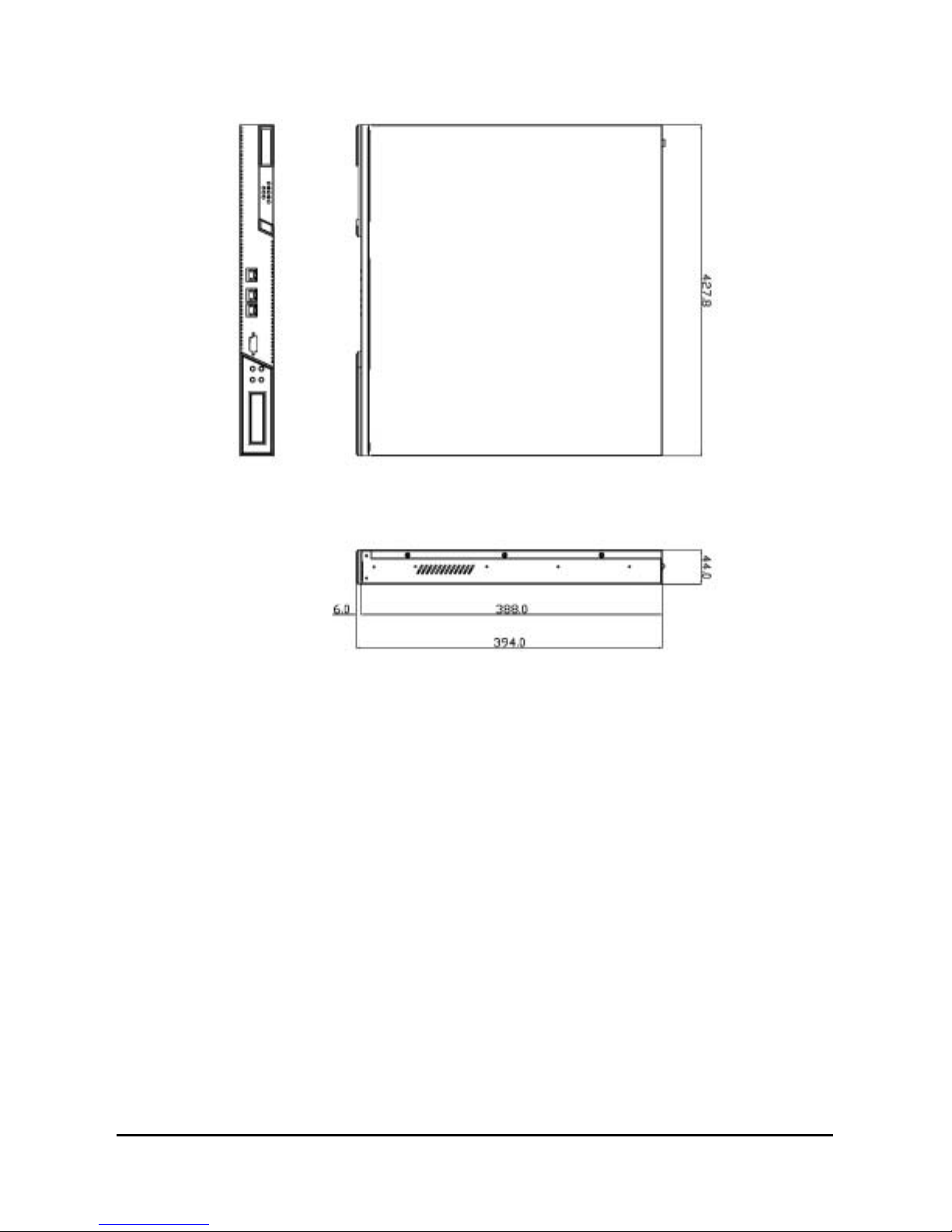
1.4 Dimensions
NA-1301 Network Appliance Server Hardware Installation Guide
Introduction
Unit: mm
6
Page 12
NA-1301 Network Appliance Server Hardware Installation Guide
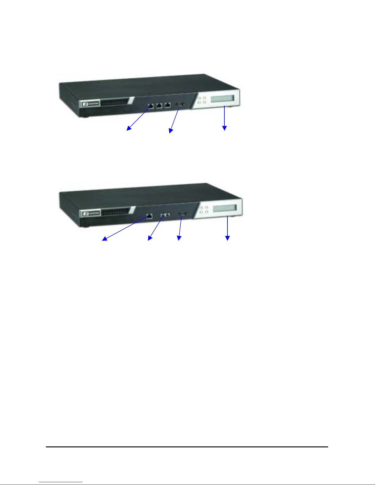
1.5 Front Panel Outlets
Located at the front panel of the NA-1301 server are the I/O outlets for connections of serial and
Ethernet interface-supported devices. You also can find out the LCD module.
The NA-1301A Server Rear Panel
Copper
w/Gigabit
Console Port
LCD Module
The NA-1301B Server Rear Panel
Copper
w/Gigabit
Multiple
mode fiber
w/ Gigabit
Console Port
LCD Module
Console port – DB-9 RS-232 Console port for command initialize and diagnostic by P.O.S.T
(Power on Self Test).
Power – Lights when the NA-1281 is powered up and performing diagnostic tests to check for
proper operation.
LAN Link – Lights up with a LAN port connection is made to another Ethernet device on the port.
100 – Show network transfer rate after link up. Maximum is up to 100Mbps
1000 – Show network transfer rate after link up. Maximum is up to 1000Mbps
Activity – Lights up when the NA-1301 transmits or receives a packet through the LAN port
Introduction
7
Page 13

NA-1301 Network Appliance Server Hardware Installation Guide
1.6 Rear Panel Outlets
Located at the rear panel of the NA-1301 series platform are the I/O outlets. Y ou will also find the main
power switch and cooling fans.
Introduction
8
Page 14

1.7 Indications of Front Panel
I. Power on LED
1. System and power on
II. HDD LED
Link/Active LED (single color)
1. The green LED is on when the HD has connection norm ally
NA-1301 Network Appliance Server Hardware Installation Guide
2. The LED flashes when there is transm it or receive activity
III. Link/Active LED (Single color)for LAN port #1, port#2 and port#3
1. The green LED is on when there is an active connection on the LAN por t
2. The LED flashes when there is transm it or receive activity to or from the
appliance
3. The LED is dark when it off line.
IV. Transmitted LED (Dual color) for LAN port #1, port#2 and port#3
1. The yellow LED light is on 10/100/1000Mbps transfer rate
2. The green LED light is on 10/100Mbps transfer rate
3. The LED is dark if the Link /Active LED is light or f lash in the sam e time; it’s on
10Mbps transfer rate
4. The LED is dark if the Link /Active LED is dark also.
There is no any networking device was attached.
Introduction
9
Page 15
C h a p t e r 2
Jumpers and Connectors
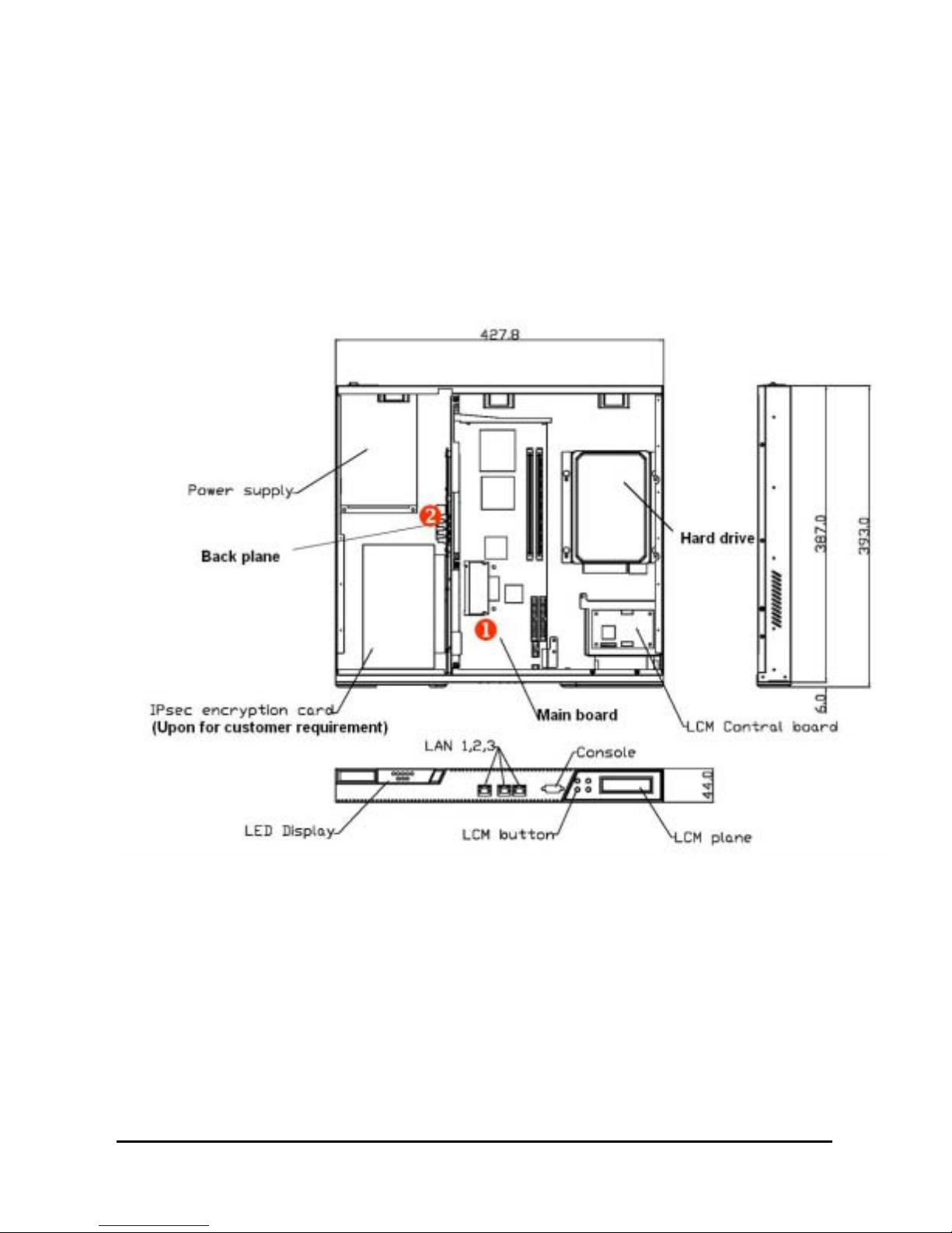
2.1 System Layout
The NA-1301 series was assembled by following major components,
They are ‘Main Board’, ‘Backplane’, ‘LCD Module’, ‘Power supply’, ‘Chassis’ and so on.
NA-1301 Network Appliance Server Hardware Installation Guide
10
Page 16
NA-1301 Network Appliance Server Hardware Installation Guide
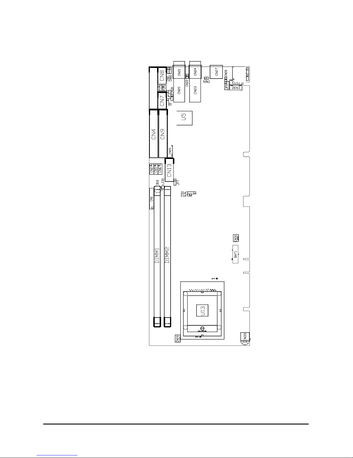
2.1.1 Main Board Layout (Jumpers and Connectors)
11
Page 17
NA-1301 Network Appliance Server Hardware Installation Guide
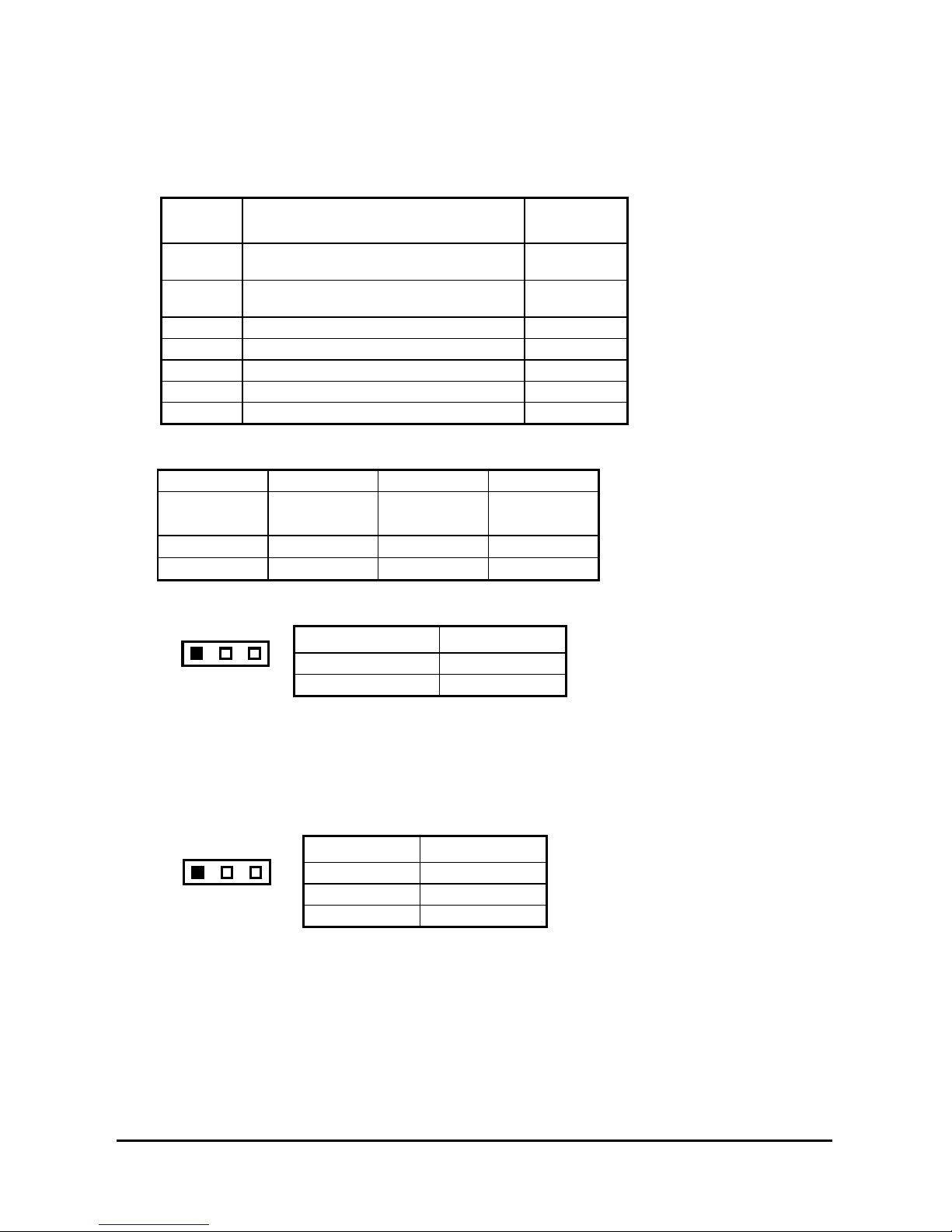
2.1.2 Jumper Settings
Making the proper jumper settings configures the main board to match the needs of your application.
The following summary table lists all onboard jumpers and their corresponding functions and/or default
settings.
Jumper Default Setting
JP1 Com 2 RS232 Setting Short
JP2 Com 2 RS232 Setting Short
JP3 Com 2 RS232 Setting Short 1-2
JP7 CMOS Clear Jumper: Norm al Mode Short 2-3
JP10 W atchdog Tr igger Mode: Disabled Open
JP12 PICMG Bus Mode Setting Open
JP13 PICMG Bus Mode Setting Open
2.1.2.1 CO M2 RS232/422/485 Settin gs: JP1,JP2,JP3
COM2 JP1 JP2 JP3
RS-232
(default)
Short 3-5,4-6 Short 3-5,4-6 Short 1-2
RS-422 Short 1-3,2-4 Short 1-3,2-4 Short 3-4
RS-485 Short 1-3,2-4 Short 1-3,2-4 Short 5-6,7-8
2.1.2.2 CM OS Clear Jumper: JP7
Options Settings
Clear CMOS Short 1-2
1
23
Normal (default) Short 2-3
Jumper
Setting
3-5,4-6
3-5,4-6
2.1.2.3 Watchdog Trigger Mode Setting: JP10
The watchdog timer is an indispensable feature of the MAINBOARD. It has a sensitive error detection
function and a report function. When the CPU processing comes to a halt, the watchdog either
generates a NMI or resets the CPU.
Options Setting
NMI Short 1-2
123
RESET Short 2-3
Disabled Open (default)
2.1.2.4 PICMG Bus Mod e and Frequency Settings: JP12/JP13
PICMG contains two PCI/PCI-X Interfaces. The PCI Interface has a 33/66 -MHz bus speed, and the
PCI-X interface has a 66/100/133-MHz bus speed. The PICMG has maximum allowed device (show
below).
12
Page 18

NA-1301 Network Appliance Server Hardware Installation Guide
BUS Mode
PCI MODE PCI-X MODE
33 MHz 66 MHz 66 MHz 100 MHz 133 MHz
Maximum Slots
4 2 4 2 1
Under normal condition, the mode and frequency of the PICMG Bus will be automatically adjusted
according to the specification of the backplane and add-on card. But in certain condition, it may be
beyond the specification of the chipset and cause failure to boot up and failure in computation, then it is
necessary to set the JP12 and JP13 according to the following table.
For example, when there are 3 pieces of PCI-X 133MHz add-on cards inser ted on the
backplane, according to the spec ification of the chips et that Maximum Slots = 1, the Bus
Mode must be must be adj usted to PCI-X 66MHz and Maximum Slots = 4 in order for a
correct operation.
JUMPER
JP13
JP12
PCI MODE PCI-X MODE
33 MHz 66 MHz 100 MHz
AUTO
Detection
ON OPEN OPEN OPEN
Short 1-2 Short 2-3 Short 3-4 OPEN
13
Page 19

NA-1301 Network Appliance Server Hardware Installation Guide
2.1.3 Connectors
The connectors allow the CPU card to connect with other parts of the system. Some problems
encountered by your system may be a result from loose or improper connections. Ensure that all
connectors are in place and firmly attached. The following table lists the function of each connector on
the main board.
Connectors Label Connectors Label
General Output Connector CN1 Primary IDE Connector CN4
COM1 CN8 Secondary IDE Connector CN9
COM2 CN7 Ethernet 3 External Speed LED CN18
USB Port 1, 2 Connector CN6 System BIOS U5
USB Port 3, 4 Connector CN5 DiskOnChip Socket U22
USB Port 5, 6 Connector CN2 Fan Power Connector 1 CN19
CRT Connector CN13 Fan Power Connector 2 CN31
External Mouse Connector CN33 Fan Power Connector 3 CN30
External Keyboard Connector CN32 Internal Buzzer BU1
ATX SB5V Power Connector CN15 Internal Battery BAT1
ATX12V CPU Power
Connector
Ethernet Connector 1
Copper
Fiber
Ethernet Connector 2
Copper
Fiber
Ethernet Connector 3
Ethernet 1 External Speed
LED
Ethernet 2 External Speed
LED
CN35 184-Pin DDR Mem ory
( Channel-A )
CN24
CN23
184-Pin DDR Memory
( Channel-B )
CN21
Socket 479 CPU Socket U13
CN20
CN27 Ethernet 1 External Link/ACT
LED
CN16 Ethernet 2 Exter nal Link/ACT
LED
CN11 Ethernet 3 Exter nal Link/ACT
LED
DIMM
1
DIMM
2
CN26
CN22
CN28
NOTE:
1. LAN1 and LAN2 is Intel 82546 and LAN3 is Intel 82540.
14
Page 20

NA-1301 Network Appliance Server Hardware Installation Guide
NA-1301 Network Appliance Server Hardware Installation Guide
2.2.1 Backplane Layout (Jumpers and Connectors) 2.2.1 Backplane Layout (Jumpers and Connectors)
15
15
Page 21

NA-1301 Network Appliance Server Hardware Installation Guide
Connectors & Settings
Jumper
JP1
Open: System power ON/OFF via JP2
Description
Short: System power always ON
Short 1-2: System power ON/OFF either by front
JP2
panel power button CN5 or via ACPI
compliant Microsof t W indows software
Short 2-3: System power ON/OFF via front panel
power button CN5
CN6 Exter nal SMI connector to front panel
CN7
6-pin cable to CPU card; used for Micr osoft
Windows Soft -power ON/OFF (ACPI com pliant)
CN5 Power ON/OF F push button connector to f ront
panel
J1 PCI VIO : PCI1 & PCI2 VIO select 3.3V / 5V
VIO = 5V , short 1- 3 & 2-4 ( Default )
O
O
1
2
VIO = 3.3V , short 3-5 & 4-6
O
O
1
2
Attention :
The setting of voltage is based on the PCI Add-O n
card used, and at the same tim e to adjust J1 and
green slot-inserting according to the label in the PCI
slot. It m ay cause short circuit or unpredictable
result if the adjustm ent is not properly set. If you
could not identify the voltage of PCI Add-On card,
please not to adjust default setting of J1 and gr een
slot-inserting.
16
Page 22

Pin Assignments
20-pin ATX Power Connector: CN4
NA-1301 Network Appliance Server Hardware Installation Guide
Brown 3.3V
Blue -12V
Black GND
Green PS-ON
Black GND
Black GND
Black GND
White -5V
Red 5V
Red 5V
Output Power Connectors: CN3
11 1
12 2
13 3
14 4
15 5
16 6
17 7
18 8
19 9
20 10
3.3V Brown
3.3V Brown
GND Black
5V Red
GND Black
5V Red
GND Black
PW-OK Orange
5VSB Purple
12V Yellow
17
87654321
+
G
G
N
N
D
D
-
3
5
5
.
V
V
3
S
V
B
+
5
V
1
1
2
2
V
V
Page 23

NA-1301 Network Appliance Server Hardware Installation Guide
C h a p t e r 3
Installation Procedures
3.1 Pre installation Checklist
In addition to this installation guide, make sure you have the following items,
The NA-1301 network appliance hardware platfo rm
Power cord
Utility CD (including this installation guide)
Mounting screws for disk drive and screws used in this appliance for spar e
Quick installation guide
Hardware Installation Guide
NA-1301 cable kits (1 x 40-pin IDE, 1 x console cable, 1 x PS/2 keyboard and mouse
cable, 1 x VGA cable)
Mounting brackets for r ack installation (lef t/right) x 2
Plastic stand for stack –up x 4
If you ordered options for the appliance, this package might contain additional hardware or publications
for those options.
Hardware Description
18
Page 24

NA-1301 Network Appliance Server Hardware Installation Guide
3.2 Setting up the app liance
This section provides the information about the initial installation to setup the NA-1301
3.2.1 Removing and Replacing the Top Cover
To gain access into the internal components of the NA-1301, you must follow the instructions given
below to remove the top cover.
19
Hardware Description
Page 25

NA-1301 Network Appliance Server Hardware Installation Guide
Hardware Description
20
Page 26

NA-1301 Network Appliance Server Hardware Installation Guide
XMain Board
3.2.2 Installing a Microprocesso r (CPU)
1. Using the method shown in Figure 1, place the new processor into the socket. Align the processor’s
pin A1 with the arrow on the micro-FCPGA socket. The pin A1 of the processor is identified with an
embroidered corner and the pin A1 of the socket is identified with a small arrow. If the processor
does not drop completely into the socket, turn the actuator until the processor drops completely in.
Note: You should not have to press down on the processor. If the processor does not drop
completely into the socket, turn the actuator until the processor drops completely in.
Figure 1: Aligning the Processor in the Socket
2. While gently holding the processor down with your finger, secure the processor in the socket by
closing the socket actuator with a screw driver.
Figure 2: Disengaging or closing the Socket Actuator
3. Reattach the cooling system, and reassemble the system per documentation that came with the
system.
21
Hardware Description
Page 27

NA-1301 Network Appliance Server Hardware Installation Guide
3.3 CPU Coo ler Installation (PKP169C01F12)
1. For the first time of installation, please do it step by step.
2. For the second time or later installation, please start from step3.
Step1. Remove the liner on the insulator.
a
g
n
m
i
t
a
t
a
S
n
i
m
a
L
M
3
v
i
s
e
h
d
A
M
T
a
t
S
K
r
a
m
a
t
S
a
L
M
T
K
r
a
i
t
m
a
n
i
m
Step2. Remove the release liner on the thermal tape. Be sure that the blue film has been removed
with the liner. (Only left the magenta thermal interface on the base of the heat sink)
Step3. Install the Back-Plate at the backside of the Mother-Board, when the Mother-Board and
CPU has been installed in the system, lay the cooler on the CPU.
Hardware Description
22
Page 28

NA-1301 Network Appliance Server Hardware Installation Guide
Step4. Fasten the cooler on the CPU as follow:
23
Hardware Description
Page 29

NA-1301 Network Appliance Server Hardware Installation Guide
THE CLIP IS WELL FASTENING!
Step5. Connect the housing to the Power-Socket.
Hardware Description
24
Page 30

NA-1301 Network Appliance Server Hardware Installation Guide
Attention: When you handle electrostatic discharge-sensitive (ESDs), take precautions to avoid
damage from static electricity.
3.4 Installing a memory module (DIMM )
The main board can supports two 184-pin DDR socket for a maximum total memory up to 4GB
ECC Memory
.
Register
The E7501 (north bridge) can support Single- and Dual-Channel Operation
1.
In single-channel operation DIMM2 is disabled. Only DIMM1 need be added.
2.
In dual-channel mode the memory populated in the two channels must be identical DIMM
configurations. The configuration consists of the same number of physical rows or banks(1 or 2),
row address bits, column address bits, the same technology part (128-Mb, 256-Mb,512-Mb), and
the same DRAM chip width (x4, x8). It is not necessary to match DIMM timings. A CL=2.0 DIMM
can be paired with a CL=2.5 DIMM as long as the geometry matches.
Attention: When you handle electrostatic discharge-sensitive (ESDs), take precautions to avoid
damage from static electricity.
3.5 Installing a DMA/66/100 hard drive
To accommodate the fast transfer rate of Ultra DMA/66/100, an 80-conductor cable (with 40 pin
connectors on both ends) is necessary when installing Ultra DMA/66/100 drives. The NA-1301, on this
aspect, can support a total of 2 Ultra DMA/66/100 drives. It is through the IDE Connector (CN4) where
the 80-conductor cable is connected. The diagram below illustrates the proper installation procedure,
including color coding of connectors, of the 80-conductor cable.
Blue ATASTM for
system board's
40-pin IDE
connector
Black ATAS
for Master Drive
TM
80-pin Ultra DMA/66/100 cable
Red stripe
represents pin 1 of
cable
ATA/33
Cable with
40 conductors
25
Hardware Description
Grey ATASTM for
Slave Drive
ATA/66/100
Cable with
80 conductors
Page 31

NA-1301 Network Appliance Server Hardware Installation Guide
3.6 Inst alling Display Interface
3.6.1 CRT Interface Controller
The built-in ATI Rage XL is a high-performance super VGA display controller with onboard 8M bytes
VGA RAM. It is capable of driving a wide array of CRT displays. It can also support CRT at a maximum
resolution of up to 1600x1200 with 16-bit colors.
The software solution provider can see the software progress status through VGA display by its header
of the main board.
3.6.2 Features
Fully compatible with IBM VGA
CRT monitor can be displayed sim ultaneously
Onboard 8M bytes VGA SDRAM
Supports non-interlaced CRT m onitors with resolutions up to 1600x1200
16-bit colors
Direct interface to Color and Monochrom e Dual Drive and Single Drive panels
SMARTMAP intelligent color to gray scale conversion enhances text legibility
Integrated programm able linear address featur e accelerates GUI per formanc e
Hardware Windows acc eleration
3.6.3 VGA Connectors
The main board support CRT VGA displays, individually or simultaneously. CN13 is a 16-pin pin
header connector commonly used for the CRT VGA display connection.
Attention: You can find out this VGA cable through cable kit in the default package.
CN13: CRT/VGA Connector Pin Assignment
Pin Signal Pin Signal Pin Signal
1 Red 2 AGND 3 Green
4 N/A 5 Blue 6 AGND
7 N/A 8 DDC
9 GND
DAT
10 AGND 11 GND 12 Horizontal
Sync
13 AGND 14 Vertical
15 DDC CLK
1
3
5
7
9
11
13
15
2
4
6
8
10
12
14
16
Sync
16 No
connecto
r
3.7 Installing Serial Port Interface
The serial interface onboard consists of COM1 port (CN8) and COM2 (CN7) supports RS-232/422/485
Hardware Description
26
Page 32

NA-1301 Network Appliance Server Hardware Installation Guide
)
)
3.7.1 Serial Ports IRQ Selection
This main board uses two 10-pin connectors for COM1 (CN8) and COM2 (CN7). In general, we use the
COM1 to communicate with LCD module which like as a command channel to LCD module by software
programming. As for the COM2, it should be a console port for this device. Which way can supports
customer doing self test or diagnostic to this device.
Interrupt Requests on COM1 and COM2 are selected via IRQ4 and IRQ3 respectively. Additionally, both
ports can be enabled or disabled via BIOS setting.
RS-232/422/485 PIN Assignment: CN8,CN7
CN8
D-SU
RS-232 RS-422 RS-485
1 1 Data Carrier TX- Data 2 6 Data Set Ready(DSR
NC NC
3 2 Receive Date(RXD) TX+ Data +
4 7 Request to Send(RTS
NC NC
5 3 Transmit Data(TXD) RX+ NC
6 8 Clear to Send(CTS) NC NC
7 4 Data Terminal Ready RX- NC
8 9 Ring Indicator(RI) NC NC
9 5 GND GND GND
10 X NC NC NC
3.8 Installing Keyboard and PS/2 Mouse Connectors
The NA-1301 provides External keyboard (CN32) and Mouse (CN33) interface with two 5-pin
connectors for porting software easily by customer.
27
Hardware Description
Page 33

CN32/CN33
NA-1301 Network Appliance Server Hardware Installation Guide
12 543
Data
Clock
GND
Power
No Connection
3.9 Installing USB Connector (Optional)
The Universal Serial Bus (USB) connector on the main board is for installation of peripherals supporting
the USB interface. CN2/CN5/CN6 is the 10-pin USB connector on the main board.
3.10 Installing ATX SB5V Power Con nector
The interface enables and supports reliable power management through improved hardware and
operating system coordination. The specification enables new power management technology to evolve
independently in operating systems and hardware while ensuring that they continue to work together.
CN15 on the MAINBOARD is a 6-pin header connector that provides ATX SB5V Power.
CN15
E
P
S
W
B
_
G
O
5
N
V
N
D
X
P
W
T
S
_
G
M
P
N
N
I
D
1
23456
3.11 Installing ATX12V CPU Power Conn ector: CN35
This connector connected to an ATX12V power supply and used for CPU Core Voltage.
Important Note: Make sure your ATX12V power supply can provide as below
+12V > 6A, +5V > 15A, -12V > 0.1A, +5VSB > 1A.
The system may become unstable and may experience difficulty powering up if the power supply is
inadequate.
1
USB Power
USB P0-
USB P0+
USB GND
AGND
2
910
USB Power
USB P1-
USB P1+
USB GND
AGND
Power Supply Specifications
28
Page 34

NA-1301 Network Appliance Server Hardware Installation Guide
3.12 Installing and Program LCD Module
1. Working flow
Communicate with PC through console cable
a) Baud Rate = 9600
b) Data Bits = 8
c) Stop Bits = 2
d) Parity Check = None
In fact, the COM Port is only use two signal as Tx and & Rx in data transaction
The LCD module model name was called AX89063. The PC with AX89063 connection is
should be PIN To PIN assignment.
The LCD is “16 by 2”,it show 16 words in each row. And can show totally 32 words with two
rows.
2. Data transfer format
A) command:
0D hex:PC AX89063
It moves the cursor to the entry point (on left upper corner of LCM)。
Attention:
It is just move the RAM flag to point out into the entry point of LCM. It needs to be
progress this commands about 40μs。
If we need to clear the contents in show up, it needs to be progress this commands
about 1.6ms。
The transfer rate should be 1.15msec per byte if we use baud rate as 9600. So the time
interval should be 0.5msec for next commands initialization 。
B) data:PC AX89063
The showing data total length should be 80 Bytes of LCM, supposedly.。But, it is only can
display 1 to 16 words and 41 to 56 words。
If would like to show the words with two rows of LCM, the PC need to send the 80 bytes
totally。
The each character will be fill in into the RAM of LCM which it was initialized through the
console port。
29
Power Supply Specifications
Page 35

NA-1301 Network Appliance Server Hardware Installation Guide
For example:
The PC sends following string to LCM which is totally 80 characters
String =
Welcome>>AX89063************************Test>Program>>>>************************
LCM will display strings as following,
Welcome>>AX89063
Test>Program>>>>
As for the ‘*’ character, therefore it doesn’t show off in the LCM. But it will be stored in
the RAM of LCM。
C) Keypad data:AX89063 PC
a) ▲ ( Up ):when it was press then release,the LCM will send 55hex to PC,
It is ASCII code for ’U’。
b) ▼ ( Down ):when it was press then release,the LCM will send 44hex to
PC,it is ASCII code for ’D’。
c) ESC:when it was press then release, the LCM will send 4Chex to PC,it is
ASCII code for ’L’。
d) Enter:when it was press then release, the LCM will send 52hex to PC,it is
ASCII code for ’R’。
3. Fronts table of LCM:( as following figure )
The front type display is following internal front table of LCM,the ASCII code for English characters
and Arabic numerals is same as with PCs。
For special symbols, the PC must send concurrent characters to LCM. Then it can show off the
right information。
Power Supply Specifications
30
Page 36

NA-1301 Network Appliance Server Hardware Installation Guide
31
Power Supply Specifications
Page 37

NA-1301 Network Appliance Server Hardware Installation Guide
C h a p t e r 4
Award BIOS Utility
Chapter 8 describes the different settings available in the Award BIOS that comes with the SBC81871
CPU card. Also contained here are instructions on how to set up the BIOS configuration.
4.1 BIOS Introduction
The Award BIOS (Basic Input/Output System) installed in your computer system’s ROM supports Intel
Celeron processors in a standard IBM-AT compatible I/O system. The BIOS provides critical low-level
support for standard devices such as disk drives, serial and parallel ports. It also adds virus and
password protection as well as special support for detailed fine-tuning of the chipset controlling the
entire system.
4.2 BIOS Setup
The Award BIOS provides a Setup utility program for specifying the system configurations and settings.
The BIOS ROM of the system stores the Setup utility. When you turn ON the computer, the Award BIOS
is immediately activated. Pressing the <Del> key immediately allows you to enter the Setup utility. If you
are a little bit late pressing the <Del> key, POST (Power On Self Test) will continue with its test routines,
thus preventing you from invoking the Setup. If you still wish to enter Setup, restart the system by
pressing the ”Reset” button or simultaneously pressing the <Ctrl>, <Alt> and <Delete> keys. You can
also restart by turning the system OFF and back ON again. The following message will appear on the
screen:
Press <DEL> to Enter Setup
In general, you press the arrow keys to highlight items, <Enter> to select, the <PgUp> and <PgDn>
keys to change entries, <F1> for help and <Esc> to quit.
When you enter the Setup utility, the Main Menu screen will appear on the screen. The Main Menu
allows you to select from various setup functions and exit choices.
Phoenix – AwardBIOS CMOS Setup Utility
Standard CMOS Features Frequency/Voltage Control
Advanced BIOS Features Load Optimized Defaults
Advanced Chipset Features Set Supervisor Password
Integrated Peripherals Set User Password
Power Management Setup Save & Exit Setup
PnP/PCI Configurations Exit Without Saving
PC Health Status
Esc : Quit F9: Menu in BIOS
F10 : Save & Exit Setup
Time, Date, Hard Disk Type…
← : Select Item
The section below the setup items of the Main Menu displays the control keys for this menu. Another
section located at the bottom of the Main Menu, just below the control keys section, displays
information on the currently highlighted item in the list.
NOTE:
If you find that your computer cannot boot after making and saving system changes with Setup, the
Award BIOS, via its built-in override feature, resets your system to the CMOS default settings.
Power Supply Specifications
32
Page 38

NA-1301 Network Appliance Server Hardware Installation Guide
We strongly recommend that you avoid making any changes to the chipset defaults. These defaults
have been carefully chosen by both Award and your system manufacturer to provide the absolute
maximum performance and reliability.
4.3 Standard CMOS Setup
“Standard CMOS Setup” allows you to record some basic hardware configurations in your computer
system and set the system clock and error handling. If the motherboard is already installed in a working
system, you will not need to s elec t th is opti on. You will need to run the Standard CMOS option, however,
if you change your system hardware configurations, the onboard battery fails, or the configuration
stored in the CMOS memory was lost or damaged.
Phoenix – AwardBIOS CMOS Setup Utility
Standard CMOS Features
Date (mm:dd:yy) Thu, Jun 25 2002 Item Help
Time (hh:mm:ss) 19 : 35 : 59
Menu Level
IDE Primary Master
IDE Primary Slave
IDE Secondary Master
IDE Secondary Slave
Century
Video EGA/VGA
Halt on All, But keyboard
Base Memory 640K
Extended Memory 65472K
Total Memory 1024K
: Move Enter: Select +/-/PU/PD: Value F10: Save ESC: Exit F1:
F5: Previous Valu es F6: Fa il-Safe Defa ults F7: Op timized De faults
None Change the
Day, month,
Year and
General Help
At the bottom of the menu are the control keys for use on this menu. If you need any help in each item
field, you can press the <F1> key. It will display the relevant information to help you. The memory
display at the lower right-hand side of the menu is read-only. It will adjust automatically according to the
memory changed. The following pages describe each item of this menu.
Date
The date format is <day>, <date> <month> <year>. Press <F3> to show the calendar.
day
date
month The month, Jan through Dec.
year The year, depends on the year of BIOS
The day of week, from Sun to Sat, determined by the BIOS,
is read only
The date, from 1 to 31 (or the maximum allowed in the
month), can key in the numerical / function key
Time
The time for mat is <hour> <m inute> <second> acc epting either function k ey or numerical
key. The time is calculated bas ed on the 24-hour military-tim e clock. For example, 1 p.m .
is 13:00:00.
Primary Master/Primary Slave/Secondary Master/Secondary Slave
The categories identify the types of one channel that have been installed in the com puter.
There are 45 predefined types and 2 user definable types are for Enhanc ed IDE BIOS.
Type 1 to Type 45 are predefined. Type User is user-definable.
Press <PgUp>/<+> or <PgDn>/<− > to select a numbered har d disk type or type the
33
Power Supply Specifications
Page 39

NA-1301 Network Appliance Server Hardware Installation Guide
number and press <Enter>. Note that the s pecifications of your drive must matc h with the
drive table. The hard disk will not work properly if you enter improper inform ation within
this category. If your hard disk drive type does not match or is not listed, you can use
Type User to define your own drive type manually.
If you select Type User, related information is as ked to be entered to the following item s.
Enter the information direc tly from the keyboard and press <Enter >. This infor mation
should be provided in the documentation fr om your hard disk vendor or the s ystem
manufacturer.
If the controller of HDD interface is ESDI, select “Type 1”.
If the controller of HDD interface is SCSI, select “None”.
If the controller of HDD interface is CD-ROM, select “None”.
CYLS. number of cylinders LANDZONE landing zone
HEADS number of heads SECTORS number of sectors
PRECOMP write precom MODE HDD access mode
If there is no hard disk dr ive installed, select NONE and pres s <Enter>.
Halt On
This field determ ines whether the system will halt if an error is detected during power up.
No errors
All errors
All, But Keyboard
All, But Diskette
All, But Disk/Key
The system boot will halt on any error detected. (default)
Whenever the BIO S detects a non-fatal err or, the system
will stop and you will be prompted.
The system boot will not stop for a k eyboard error; it will
stop for all other errors.
The system boot will not stop for a disk error; it will stop f or
all other errors.
The system boot will not stop for a k eyboard or disk error; it
will stop for all other errors.
Power Supply Specifications
34
Page 40

NA-1301 Network Appliance Server Hardware Installation Guide
4.4 Advanced BIOS Features
This section allows you to configure and improve your system and allows you to set up some system
features according to your preference.
Phoenix – AwardBIOS CMOS Setup Utility
Advanced BIOS Features
Virus Warning Disabled Item Help
CPU L1 & L2 Cache Enabled Menu Level
Quick Power On Self Test Enabled
First Boot Device HDD-0 Allows you to
Second Boot Device HDD-0 choose the VIRUS
Third Boot Device CDROM warning feature
Boot Other Device Enabled for IDE Hard disk
Boot Up NumLock Status On boot sector
Gate A20 Option Fast protec tion. If this
Typematic Rate Setting Disabled function is enable
Typematic Rate (Chars/Sec) 6 and someone
Typematic Delay (Msec) 250 attempts to write
Security Option Setup data into this area,
MPS Version Control For OS 1.4 BIOS will show
OS Select For DRAM > 64MB Non-OS2 a warni ng
Console Redirection Enable message on
Baud Rate [9600] sc reen and alarm
Agent Connect via [Null] beep
Agent Wait Time (min) 1
Agent after boot Disable
Report No FDD For WIN 95 No
Small Logo(EPA) Show Disabled
: Move Enter: Select +/-/PU/PD: Value F10: Save ESC: Exit F1:
General Help
Virus Warning
This item protects the boot sector and partition table of your hard disk against accidental
modifications. If an attem pt is m ade, the BIOS will halt the system and display a warning
message. If this oc curs, you can either allow the operation to continue or run an
anti-virus program to loc ate and remove the problem .
NOTE:
Many disk diagnostic programs, which attempt to access the boot sector table, can cause the
virus warning. If you will run such a program, disable the Virus Warning feature.
CPU L1 & L2 Cache
These two categories speed up m emory access. However, it depends on CPU/chipset
design.
Enabled Enable cache
Disabled Disable cache
Quick Power On Self Test
This option speeds up Power On Self T est (POST) after you turn on the system power. If
set as Enabled, BIOS will shorten or skip s ome check items during POST. T he default
setting is “Enabled ”.
Enabled Enable Quick POST
Disabled Normal POST
First/Second/Third Boot Device
These items allow the selec tion of the 1
st
, 2nd, and 3rd devices that the system will search
for during its boot-up sequence. T he wide range of selection includes F loppy, LS120,
ZIP100, HDD0~3, SCSI, and CDROM.
35
Power Supply Specifications
Page 41

NA-1301 Network Appliance Server Hardware Installation Guide
Boot Other Device
This item allows the user to enable/disable the boot device not listed on the First/Second/Third
boot devices option above. The default setting is Enabled.
Boot Up NumLock Status
This option enables and disables the num berlock f unction of the k eypad. The default
value is “On”.
On Keypad functions confine with numbers
Off
Keypad functions convert to special functions (i.e., left/right arrow keys)
Gate A20 Option
The default value is “Fast”.
Normal
Fast
The A20 signal is controlled by keyboard controller or chipset hardware.
Default: Fast. The A20 signal is controlled by Port 92 or chipset specific
method.
Typematic Rate Setting
This determines the typematic r ate of the keyboard. The def ault value is “Disabled”.
Enabled Enable typematic rate and typematic delay programming
Disabled
Disable typematic rate and typematic delay programming. The system
BIOS will use default value of these 2 items and the default is controlled
by keyboard.
Typematic Rate (Chars/Sec)
This option refers to the num ber of char acters the keyboard can type per second. The
default value is “6”.
6 6 characters per second
8 8 characters per second
10 10 characters per second
12 12 characters per second
15 15 characters per second
20 20 characters per second
24 24 characters per second
30 30 characters per second
Typematic Delay (Msec)
This option sets the display time interval fr om the firs t to the second character when
holding a key. The default value is “250”.
250 250 msec
500 500 msec
750 750 msec
1000 1000 msec
Security Option
This item allows you to limit acces s to the system and Setup, or just to Setup. The default
value is “Setup”.
System
The system will not boot and access to Setup will be denied if
the incorrect password is entered at the prompt.
Power Supply Specifications
36
Page 42

NA-1301 Network Appliance Server Hardware Installation Guide
Setup
The system will boot, but access to Setup will be denied if the
correct password is not entered at the prompt.
NOTE: To disable security, select PASSWORD SETTING at Main Menu and then you will be asked
to enter password. Do not type anything, just press <Enter> and it will disable security. Once
the security is disabled, the system will boot and you can enter Setup freely.
MPS Version Control For OS
This item allows you to select the version of MPS table for NT 4.0.
The choice: 1.1, 1.4
OS Select for DRAM > 64MB
This segment is specifically created for O S/2 when DRAM is larger than 64MB. If your
operating system is OS/2 and DRAM used is larger the 64MB, you have to select “OS 2”,
otherwise (under non-OS2), default is NON- OS2. The default value is “Non-OS2”.
Console Redirection
This item allows you to enable or disable the BIOS boot up and redirect to c onsole port
feature. The choice: Enable, Disable
Baud Rate
This item allows you to setup the data transfer r ate for the console port. T he default value
is 9600.
The choice: 9600, 19200, 38400, 57600 and 115200
Agent Connect via
This item is j ust highlight the routing between console port with PC client. The def ault
value should be Null.
Agent Waiting Time
This item is j ust highlight the polling timer. If the console port doesn’t receive the inquiry
from PC client in the tim e fram e. It will be cut out the monitoring path for BIOS booting
from console. T he default value should be 1 m inutes.
The choice: 1, 2, 4 and 8
Agent After Boot
This item allows you to enable or disable the agent after boot.
The choice: disable, enable
37
Power Supply Specifications
Page 43

NA-1301 Network Appliance Server Hardware Installation Guide
4.5 Advanced Chipset Features
Since the features in this section are related to the chipset on the CPU board and are completely
optimized, you are not recommended to change the default settings in this setup table unless you are
well oriented with the chipset features.
Phoenix – AwardBIOS CMOS Setup Utility
Advanced Chipset Features
DRAM Timi ng Control
Memory Frequency For Auto
System BIOS Cacheable Enabled Menu Lev el
Video BIOS Cacheable Disabl ed
Memory Hole At 15M-16M Disabled
Delayed Transaction Enabled
Delay Prior to Thermal 16 Min
AGP Aperture Size (MB) 64
: Move Enter: Select +/-/PU/PD: Value F10: Save ESC: Exit F1:
General Help
F5: Previous Valu es F6: Fa il-Safe Defa ults F7: Op timized De faults
[Press Enter]
Item Help
DRAM Timing Control
Press “Enter” setting DRAM timming as below.
Phoenix – AwardBIOS CMOS Setup Utility
Advanced Chipset Features
DRAM Timing Selectable
CAS Latency Time 2
Active to Precharge Delay 5 Menu Level
DRAM RAS# to CAS# Delay 2
DRAM RAS# Precharge 2
: Move Enter: Select +/-/PU/PD: Value F10: Save ESC: Exit F1:
General Help
By SPD
Item Help
CAS Latency Time
When synchronous DRAM is installed, the number of clock cycles of CAS latency depends on
the DRAM timing.
The Choice: 1.5, 2, 2.5.
Active to Precharge Delay
This item controls the number of DRAM clocks f or TRAS.
The Choice: 7, 6, 5.
DRAM RAS# to CAS# Delay
This field let’s you insert a timing delay between the CAS and RAS strobe signals,
used when DRA M is writ ten to, r ead from , or ref reshed. Fast g ives faster perform ance;
and Slow gives more stable perfor mance. This f ield applies only when synchronous
DRAM is installed in the system.
The Choice: 3, 2.
DRAM RAS# Precharge
If an insufficient num ber of cycles is allowed for the RAS to ac cumulate its c harge
Power Supply Specifications
38
Page 44

NA-1301 Network Appliance Server Hardware Installation Guide
before DRAM refresh, the ref resh may be incom plete and the DRAM may fail to retain
data. Fast gives faster perf ormanc e; and Slow gives more stable per formanc e. T his
field applies only when synchronous DRAM is installed in the system.
The Choice: 2, 3.
System BIOS Cacheable
Selecting Enabled allows caching of the system BIOS ROM at F0000h-FFFFFh, resulting
in better system perform ance. However, if any program writes to this mem ory area, a
system error may result.
The choice: Enabled, Disabled.
Video BIOS Cacheable
Select Enabled allows caching of the video BIOS, resulting in better system perform ance.
However, if any program writes to this mem ory area, a system error m ay result.
The Choice: Enabled, Disabled.
Video RAM Cacheable
Select Enabled allows caching of the A/B segm ent, resulting in better system
performance.
The Choice: Enabled, Disabled.
Memory Hole at 15MB - 16MB
In order to improve perfor mance, cer tain space in mem ory can be reserved for ISA c ards.
This field allows you to reserve 15MB to 16MB mem ory address space to ISA expansion
cards. This m akes m emor y from 15MB and up unavailable to the system. Expans ion
cards can only access mem ory up to 16MB. By default, this field is set to Disabled.
Delayed Transaction
The chipset has an embedded 32- bit posted write buffer to s upport delay transactions
cycles. Select Enabled to support compliance with PCI specification version 2.1. T he
default setting is Enable.
39
Power Supply Specifications
Page 45

NA-1301 Network Appliance Server Hardware Installation Guide
4.6 Integrated Peripherals
This option sets your hard disk configuration, mode and port.
Phoenix – AwardBIOS CMOS Setup Utility
Integrated Peripherals
On-Chip Primary PCI IDE
IDE Primary Master PIO
IDE Primary Slave PIO Auto Menu Level
IDE Primary Master UDMA Auto
IDE Primary Slave UDMA Auto
On-Chip Secondary PCI IDE Enabled
IDE Secondary Master PIO Auto
IDE Secondary Slave PIO Auto
IDE Secondary Master UDMA Auto
IDE Secondary Slave UDMA Auto
USB Controller Enabled
USB 2.0 Controller Enable
USB Keyboard Support Disabl ed
USB Mouse Support Disable
IDE HDD Block Mode Enabled
POWER ON Function BUTTON ONLY
KB Power On Password Enter
Hot Key Power On Ctrl-F1
Onboard Serial Port 1 3F8/IRQ4
Onboard Serial Port 2 2F8/IRQ3
UART Mode Select Normal
RxD, TxD Active Hi, Lo
PWRON After PWR-Fail Off
: Move Enter: Select +/-/PU/PD: Value F10: Save ESC: Exit
F1: General Help
F5: Previous Values F6: Fail-Safe Defaults F7: Optimized Defaults
Enabled
Auto
Item Help
On-Chip Primary/Secondary PCI IDE
The integrated peripheral controller contains an IDE interface with support f or two IDE
channels. Select Enabled to activate each channel separ ately.
The choice: Enabled, Disabled.
IDE Primary/Secondary Master/Slave PIO
The four IDE PIO (Program med Input/O utput) fields let you set a PIO mode (0-4) for each
of the four IDE devices that the onboard IDE interf ace supports. Modes 0 thr ough 4
provide successively increased perfor mance. In Auto m ode, the system autom atically
determines the best m ode for each device.
The choice: Auto, Mode 0, Mode 1, Mode 2, Mode 3, Mode 4.
IDE Primary/Secondary Master/Slave UDMA
Ultra DMA/33 implementation is pos sible only if your IDE hard drive supports it and the
operating environment includes a DMA driver ( W indows 98 or a third-party IDE bus
master driver). If your hard drive and your system software both support Ultra DMA/33,
select Auto to enable BIOS support.
The Choice: Auto, Disabled.
USB Controller
Select Enabled if your system contains a Universal Serial Bus (USB) controller and you
have USB peripherals.
The choice: Enabled, Disabled.
USB 2.0 Controller
Select Enabled if your system contains a Universal Serial Bus V2.0 ( USB2.0) controller
Power Supply Specifications
40
Page 46

NA-1301 Network Appliance Server Hardware Installation Guide
and you have USB2.0 peripherals.
The choice: Enabled, Disabled.
USB Keyboard Support
Select Enabled if your system contains a Universal Serial Bus (USB) controller and you
have a USB keyboard.
The choice: Enabled, Disabled.
USB Mouse Support
Select Enabled if your system contains a Universal Serial Bus ( USB) controller and you
have a USB Mouse.
The choice: Enabled, Disabled.
IDE HDD Block Mode
Block mode is a lso called b lock transfer , multiple commands, or multiple s ector read/ write.
If your IDE hard drive supports block m ode (mos t new drives do), select Enabled for
automatic detection of the optim al number of block read/writes per sector the drive can
support.
The choice: Enabled, Disabled
POWER ON Function
This option al lows users to s elect the t ype of power ON sequence f or the system to follow.
The default value is “Button-Only”.
BUTTON-ONLY Follows the conventional way of turning OFF system power (via power button).
Upon selecting this option, the KB POWER ON Password line appears. Press <Enter> and you’ll
be prompted to enter and confirm a password of your choice.
Password
Hot KEY
After setting the password, succeeding attempts to power ON the system will result to null. For
system to activate, user must input the password via keyboard then press <Enter>.
This option is very simi lar with that of Password. Hot-key combi nations range from Ctrl-F1 to
Ctrl-F12. User may define this combination from the Hot k ey Power ON option.
KB Power ON Password
This item allows you to set the keyboard power on password.
Hot Key Power On
This item allows you to select the hot key of the keyboard power on.
The choice: Ctrl-F1~F12.
Onboard Serial Port 1/Port 2
Select an address and corresponding interr upt for the firs t and second serial ports.
The choice: 3F8/IRQ4, 2E8/IRQ3, 3E8/IRQ4, 2F8/IRQ3, Disabled, Auto.
UART Mode Select
This item allows you to select UART m ode.
The choice: IrDA, ASKIR, Normal.
RxD, TxD Active
This item allows you to determine the active of RxD, TxD.
The Choice: “Hi, Hi”, “Lo, Lo”, “Lo, Hi”, “Hi, Lo”.
PWRON After PWR-Fail
This item allows you to select if you want to power on the system after power failure.
The choice: Off, On, Form er-Sts.
41
Power Supply Specifications
Page 47

NA-1301 Network Appliance Server Hardware Installation Guide
4.7 Power Management Setup
The Power Management Setup allows you to save energy of your system effectively. It will shut down
the hard disk and turn OFF video display after a period of inactivity.
Phoenix – AwardBIOS CMOS Setup Utility
Power Management Setup
ACPI Function
Power Management Min Saving
Video Off Method DPMS Menu Level
Video Off In Suspend Yes
Suspend Type Stop Grant
MODEM Use IRQ 3
Suspend Mode 1 Hour
HDD Power Down 15 Min
Soft-Off by PWR-BTTN Instant-Off
CPU THRM-Throttling 50.0%
Wake-up by PCI card Enabled
Power On by Ring Enabled
Resume by Alarm Disabled
Date(of Month) Alarm 0
Time(hh:mm:ss) Alarm 0 : 0 : 0
** Reload Global Timer Events **
Primary IDE 0 Disabled
Primary IDE 1 Disabled
Secondary IDE 0 Disabled
Secondary IDE 1 Disabled
COM Port Disabled
PCI PIRQ[A-D]# Disabled
: Move Enter: Select +/-/PU/PD: Value F10: Save ESC: Exit F1:
F5: Previous Valu es F6: Fa il-Safe Defa ults F7: Op timized De faults
Disabled
General Help
Item Help
ACPI Function
This item allows you to enable/disable the Advanced Configuration and Power
Management (ACPI). The choic e: Enabled, Disabled.
Power Management
This item allows you to select the Power Management m ode.
The choice: User Define, Min Saving, Max Saving.
Video Off Method
In suspending, this item allows you to select the CRT closed m ethod under APM m ode.
The choice: Blank Scr een, V/H SYNC+Blank, DPMS
Video Off In Suspend
In suspending, this item allows you to select if you want to close the CRT under APM
mode.
The choice: Enabled, Disabled.
Suspend Type
This item allows you to select the suspend type. Stop G rant means wak e up by IRQ,
and PowerOn Suspend means wake up by ACPI wake up event.
The choice: Stop Grant, PwrOn Suspend.
MODEM Use IRQ
APM 1.2 function used only.
The choice: NA, 3, 4, 5, 7, 9, 10, 11
Suspend Mode
Power Supply Specifications
42
Page 48

NA-1301 Network Appliance Server Hardware Installation Guide
When enabled and af ter the set time of system inactivity, all devices except the CPU will
be shut off.
The choice: Enabled, Disabled.
HDD Power Down
When enabled and af ter the set time of system inactivity, the hard disk drive will be
powered down while all other devices remain active.
The choice: Enabled, Disabled.
Soft-Off by PWR-BTTN
Pressing the power button for more than 4 s econds forces the system to enter the
Soft-Off state when the system has “hung.”
The choice: Delay 4 Sec, Instant-Off.
CPU THRM-Throttling
Select the CPU THRM-Throttling rate.
The choice: 12.5%, 25.0%, 37.5%, 50.0%, 62.5%, 75.0%, 87.5%.
Power On by Ring
An input signal on the serial Ring Indicator (RI) line (in other words, an inc oming call on
the modem) awakens the system from a soft off state.
The choice: Enabled, Disabled.
Resume by Alarm
When Enabled, your can set the date and tim e at which the RTC (real-t ime clock ) alarm
awakens the system from Suspend mode.
The choice: Enabled, Disabled.
Primary IDE 0 The default value is “Disabled”.
Primary IDE 1 The default value is “Disabled”.
Secondary IDE 0 The default value is “Disabled”.
Secondary IDE 1 The default value is “Disabled”.
FDD, COM, LPT Port The default value is “Disabled”.
PCI PIRQ[A-D]# The default value is “Disabled”.
43
Power Supply Specifications
Page 49

NA-1301 Network Appliance Server Hardware Installation Guide
4.8 PNP/PCI Configuration
This section describes configuring the PCI bus system. PCI, or Personal Computer Interconnect, is a
system which allows I/O devices to operate at speeds nearing the speed the CPU itself uses when
communicating with its own special components. This section covers some very technical items and it is
strongly recommended that only experienced users should make any changes to the default settings.
Phoenix – AwardBIOS CMOS Setup Utility
PnP/PCI Configurations
PNP OS Installed
Reset Configuration Data Disabl ed
Menu Level
Resources Controlled By Auto (ESCD)
X IRQ Resources Press Enter Select Yes if you are
X DMA Resources Pres s Enter using a Plug and play
capable operating
PCI/VGA Palette Snoop Disabled system select No if
you need the BIOS to
configure non-boot
devices
: Move Enter: Select +/-/PU/PD: Value F10: Save ESC: Exit F1:
F5: Previous Valu es F6: Fa il-Safe Defa ults F7: Op timized De faults
No
General Help
Item Help
PNP OS Installed
This item allows you to determine install PnP O S or not. The options available are Yes
and No.
Reset Configuration Data
Normally, you leave this field Disabled. Select Enabled to reset Extended System
Configuration Data (ESCD) when you exit Setup or if you have installed a new add-on
and the system reconfiguration has caus ed such a serious c onflict that the operating
system can not boot. The options available are Enabled and Disabled.
Resource controlled by
The Award Plug and Play BIOS has the capacity to automatically configure all of the boot
and Plug and Play compatible devices. However, this capability means absolutely nothing
unless you are using a Plug and Play operating system such as W indows98. The
options available are Auto and Manual.
IRQ Resources
When res ources are contr olled manually, assign each system interrupt a type, depending
on the type of device using the interrupt.
PCI/VGA Palette Snoop
Leave this field at Disabled.
The choice: Enabled, Disabled.
Power Supply Specifications
44
Page 50

NA-1301 Network Appliance Server Hardware Installation Guide
4.9 PC Health Status
This option configures the PCI bus system. All PCI bus systems on the system use INT#, thus all
installed PCI cards must be set to this value.
CMOS Setup Utility-Copyright © 1984-2001 Award Software
PC Health Status
Current System Temp.
Current CPU1 Temperature Menu Level
Current FAN1 Speed
Current FAN2 Speed
Vcore
Vcc3
+5V
+12V
-12V
-5V
: Move Enter: Select +/-/PU/PD: Value F10: Save ESC: Exit F1:
F5: Previous Valu es F6: Fa il-Safe Defa ults F7: Op timized De faults
Current System Temp.
Show you the current system temperature.
General Help
Current CPU1 Temperature
Show you the current CPU1 temperature.
Current FAN1/FAN2 Speed
These optional and read-only fields show the current speeds in RPM ( revolution per
minute) for the CPU fan and chas sis fan as m onitored by the hardware monitoring IC.
Vcc3/+5V/+12V/-12V
Show you the voltage of +3.3V/+5V/+12V/-12V.
45
Power Supply Specifications
Page 51

NA-1301 Network Appliance Server Hardware Installation Guide
4.10 Frequency/Voltage Control
This option configures the PCI bus system. All PCI bus systems on the system use INT#, thus all
installed PCI cards must be set to this value.
CMOS Setup Utility-Copyright © 1984-2001 Award Software
Frequency/Voltage Control
Auto Detect PCI Clk Enabled
Spread Spectrum Modulated Disabled Menu Level
: Move Enter: Select +/-/PU/PD: Value F10: Save ESC: Exit F1:
F5: Previous Valu es F6: Fa il-Safe Defa ults F7: Op timized De faults
Auto Detect PCI Clk
When enabled, this item will auto detect if the DIMM and PCI soc ket have devices and
will send clock signal to DIMM and PCI devices. W hen disabled, it will send the clock
signal to all DIMM and PCI socket.
The choice: Enabled, Disabled.
General Help
Spread Spectrum Modulated
This item allows you to enable/disable the spread spectr um m odulate.
The choice: Enabled, Disabled.
4.11 Load Optimized Defaul ts
This option allows you to load the default values to your system configuration. These default settings
are optimal and enable all high performance features.
Phoenix – AwardBIOS CMOS Setup Utility
Standard CMOS Features Frequency/Voltage Control
Advanced BIOS Features Load Fail-Safe Defaults
Advanced Chipset Features Load Optimized Defaults
Integrated Peripherals Set Supervisor Password
Power Man
PnP/PCI Co
PC Health Status Exit Without Saving
Esc : Quit : Select Item
F10 : Save & Exit Setup
Load Optimized Defaults (Y/N)? N
To load SETUP defaults value to CMOS SRAM, enter “Y”. If not, enter “N”.
Power Supply Specifications
Load Optimized Defaults
46
Page 52

NA-1301 Network Appliance Server Hardware Installation Guide
4.12 Set Supervisor/User Password
You can set either supervisor or user password, or both of then. The differences between are:
supervisor password: can enter and change the options of the setup menus.
user password: just can enter but do not have the right to change the options of the setup
menus.
When you select this function, the following message will appear at the center of the screen to assist
you in creating a password.
ENTER PASSWORD:
Type the password with eight characters at most, and press <Enter>. The password typed will now
clear any previously entered password from CMOS memory. You will be asked to confirm the password.
Type the password again and press <Enter>. You may also press <Esc> to abort the selection and not
enter a password.
To disable password, just press <Enter> when you are prompted to enter password. A message will
confirm the password being disabled. Once the password is disabled, the system will boot and you can
enter Setup freely.
PASSWORD DISABLED.
When a password is enabled, you have to type it every time you enter Setup. This prevents any
unauthorized person from changing your system configuration.
Additionally when a password is enabled, you can also require the BIOS to request a password every
time the system reboots. This would prevent unauthorized use of your computer.
You determine when the password is required within the BIOS Features Setup Menu and its Security
option. If the Security option is set to “System”, the password is required during boot up and entry into
Setup. If set as “Setup”, prompting will only occur prior to entering Setup.
4.13 Save & Exit Setup
This allows you to determine whether or not to accept the modifications. Typing “Y” quits the setup utility
and saves all changes into the CMOS memory. Typing “N” brigs you back to Setup utility.
Phoenix – AwardBIOS CMOS Setup Utility
Standard CMOS Features Frequency/Voltage Control
Advanced BIOS Features Load Fail-Safe Defaults
Advanced Chipset Features Load Optimized Defaults
Integrated Peripherals Set Supervisor Password
Power Man
PnP/PCI Con
SAVE to CMOS and EXIT (Y/N)? Y
PC Health Status Exit Without Saving
Esc : Quit : Select Item
F10 : Save & Exit Setup
47
Power Supply Specifications
Save Data to CMOS
Page 53

NA-1301 Network Appliance Server Hardware Installation Guide
4.14 Quit Without Saving
Select this option to exit the Setup utility without saving the changes you have made in this session.
Typing “Y” will quit the Setup utility without saving the modifications. Typing “N” will return you to Setup
utility.
Phoenix – AwardBIOS CMOS Setup Utility
Standard CMOS Features Frequency/Voltage Control
Advanced BIOS Features Load Fail-Safe Defaults
Advanced Chipset Features Load Optimized Defaults
Integrated Peripherals Set Supervisor Password
Power Man
PnP/PCI Con
PC Health Status Exit Without Saving
Quit Without Saving (Y/N)? N
Esc : Quit : Select Item
F10 : Save & Exit Setup
Abandon all Datas
Power Supply Specifications
48
Page 54

NA-1301 Network Appliance Server Hardware Installation Guide
A p p e n d i x A
Warning
This is a class A Product. In a domestic Environment this Product may cause radio interference
in which case the user may be required to take adequate measures.
It will be danger if battery is incorrectly replaced. Replacing only with the same or equivalent type
is highly recommended by the manufacturer. Dispose of used batteries according to the
manufacturer’s instructions.
Warning for Hard Disk Drive Selection:
TUV approved Hard Disk Drive is preferred for TUV compliance Hard Disk drive-Optional,
(NWGQ2), generic, Input Voltage rated 5V dc/1.0A, 12V dc/1.8A maximum. Minimum clearance from
uninsulated live parts 4.0 mm.
“The equipment is to be installed in an environment with maximum ambient temperature must
not exceed 40°C.”
“The openings on the enclosure are for air convection hence protected the equipment from
overheating. DO NOT COVER THE OPENINGS.”
“Lay this equipment on a reliable surface when install. A drop or fall could cause injury.”
“The equipment shall be installed according to specification as nameplate. Make sure the
voltage of the power source when connect the equipment to the power outlet. The current of
load and output power of loads shall be not over the specification.”
“This equipment must be connected to the reliable earthing before using.”
Electric shock hazard inside the redundant power supply
The exchange of modules shall be done by service
person.
49
Warning
Page 55

NA-1301 Network Appliance Server Hardware Installation Guide
This page does not contain any information.
Warning
50
 Loading...