

Page 1

MANO861
Intel® LGA1155 Socket Supports
22nm / 32nm Intel® CoreTM i7 /
CoreTM i5 /
CoreTM i3 / Pentium® /
Celeron®
Mini ITX Motherboard
User’s Manual
Page 2

Disclaimers
This manual has been carefully checked and believed to contain accurate information.
Axiomtek Co., Ltd. assumes no responsibility for any infringements of patents or any third
party’s rights, and any liability arising from such use.
Axiomtek does not warrant or assume any legal liability or responsibility for the accuracy,
completeness or usefulness of any information in this document. Axiomtek does not make any
commitment to update the information in this manual.
Axiomtek reserves the right to change or revise this document and/or product at any time
without notice.
No part of this document may be reproduced, stored in a retrieval system, or transmitted, in
any form or by any means, electronic, mechanical, photocopying, recording, or otherwise,
without the prior written permission of Axiomtek Co., Ltd.
CAUTION
If you replace wrong batteries, it causes the danger of explosion. It is recommended by the
manufacturer that you follow the manufacturer’s instructions to only replace the same or
equivalent type of battery, and dispose of used ones.
Copyright 2015 Axiomtek Co., Ltd.
All Rights Reserved
May 2015, Version A2
Printed in Taiwan
ii
Page 3

ESD Precautions
Computer boards have integrated circuits sensitive to static electricity. To prevent chipsets
from electrostatic discharge damage, please take care of the following jobs with precautions:
Do not remove boards or integrated circuits from their anti-static packaging until you are
ready to install them.
Before holding the board or integrated circuit, touch an unpainted portion of the system
unit chassis for a few seconds. It discharges static electricity from your body.
Wear a wrist-grounding strap, available from most electronic component stores, when
handling boards and components.
Trademarks Acknowledgments
Axiomtek is a trademark of Axiomtek Co., Ltd.
Windows® is a trademark of Microsoft Corporation.
AMI is a trademark of American Megatrend Inc.
IBM, PC/AT, PS/2, VGA are trademarks of International Business Machines Corporation.
Intel® CoreTM i7 / CoreTM i5 / CoreTM i3 / Pentium® / Celeron® are trademarks of Intel
Corporation.
Winbond is a trademark of Winbond Electronics Corp.
Realtek is a trademark of Realtek Semi-Conductor Co., Ltd.
Other brand names and trademarks are the properties and registered brands of their
respective owners.
iii
Page 4
Warning
Information to prevent injury to yourself when trying to complete a task.
Caution
Information to prevent damage to the components when trying to complete a
task.
Important
Instructions that you MUST follow to complete a task.
Note
Tips and additional information to help you complete a task.
Conventions Used in This Manual
To make sure that you perform certain tasks properly, take note of the following symbols used
throughout this manual.
iv
Page 5

Table of Contents
Disclaimers ..................................................................................................... ii
ESD Precautions ........................................................................................... iii
Conventions Used in This Manual ............................................................... iv
Chapter 1 Introduction ............................................. 1
1.1 Features ............................................................................................... 1
1.2 Specifications ...................................................................................... 2
1.3 Utilities Supported .............................................................................. 3
Chapter 2 Board and Pin Assignments .................... 5
2.1 Board Layout ....................................................................................... 5
2.2 Rear Panel I/O ...................................................................................... 5
2.3 Jumper Settings .................................................................................. 6
2.3.1 Clear CMOS (JCMOS1) .............................................................................. 7
2.3.2 AT/ATX Power Mode Selection (JPSON) .................................................... 7
2.3.3 LVDS Backlight Power Selection (JLVDS_BKL1) ....................................... 7
2.3.4 SelectCOM Connector (SelectCOM) .......................................................... 8
2.4 Connectors .......................................................................................... 9
2.4.1 Rear Panel Connectors ............................................................................. 10
2.4.2 FAN Connectors (CPU_FAN and SYS_FAN1) ......................................... 10
2.4.3 COM Connectors (COM34 and COM56) ................................................... 11
2.4.4 GPIO Connector (JDIO) ............................................................................. 11
2.4.5 Front Panel Connector (F_PANEL1) ......................................................... 12
2.4.6 Power Connectors (EATXPWR and ATX12V)........................................... 13
2.4.7 Internal Audio Connector (FPAUD1) ......................................................... 14
2.4.8 LVDS Connector (JLVDS) ......................................................................... 14
2.4.9 LCD Inverter Connector (JBKL) ................................................................ 15
2.4.10 Serial ATA Connectors (SATA1~SATA3) ................................................... 15
2.4.11 USB Connector (USB78) .......................................................................... 15
2.4.12 SPI Connector (SPI1) ................................................................................ 16
2.4.13 LPC Connector (JLPC) ............................................................................. 16
2.4.14 LPT Connector (LPT) ................................................................................ 17
Chapter 3 Hardware Installation ........................... 19
3.1 Motherboard Overview ..................................................................... 19
3.1.1 Placement Direction .................................................................................. 19
3.1.2 Screw Holes .............................................................................................. 19
v
Page 6

3.2 Central Processing Unit (CPU) ......................................................... 20
3.2.1 Installing the CPU ...................................................................................... 21
3.2.2 Installing the CPU Heatsink and Fan ........................................................ 23
3.3 System Memory ................................................................................. 24
3.3.1 Overview ................................................................................................... 24
3.3.2 Memory Configurations ............................................................................. 25
3.3.3 Installing a SO-DIMM ................................................................................ 25
3.3.4 Removing a SO-DIMM .............................................................................. 26
3.4 Expansion Card ................................................................................. 27
3.4.1 Installing an Expansion Card..................................................................... 27
3.4.2 Configuring an Expansion Card ................................................................ 27
3.4.3 PCI-Express x4 Slot .................................................................................. 27
3.4.4 PCI-Express Mini Card Connector ............................................................ 28
Chapter 4 Hardware Description ........................... 29
4.1 Microprocessors ............................................................................... 29
4.2 BIOS ................................................................................................... 29
4.3 System Memory ................................................................................. 29
4.4 I/O Port Address Map ................................ ................................ ........ 30
4.5 Interrupt Controller (IRQ) Map ......................................................... 32
4.6 Memory Map ...................................................................................... 35
Chapter 5 AMI BIOS Setup Utility .......................... 37
5.1 Starting ............................................................................................... 37
5.2 Navigation Keys ................................................................................ 37
5.3 Main Menu .......................................................................................... 39
5.4 Advanced Menu ................................................................................. 40
5.5 Chipset Menu ..................................................................................... 51
5.6 Boot Menu .......................................................................................... 59
5.7 Save & Exit Menu .............................................................................. 60
Appendix A Watchdog Timer ................................... 61
About Watchdog Timer ................................................................................ 61
How to Use Watchdog Timer ....................................................................... 61
Sample Program .......................................................................................... 62
Appendix B Digital I/O ............................................. 63
About Digital I/O ........................................................................................... 63
Digital I/O Programming .............................................................................. 63
vi
Page 7

vii
Page 8

Page 9
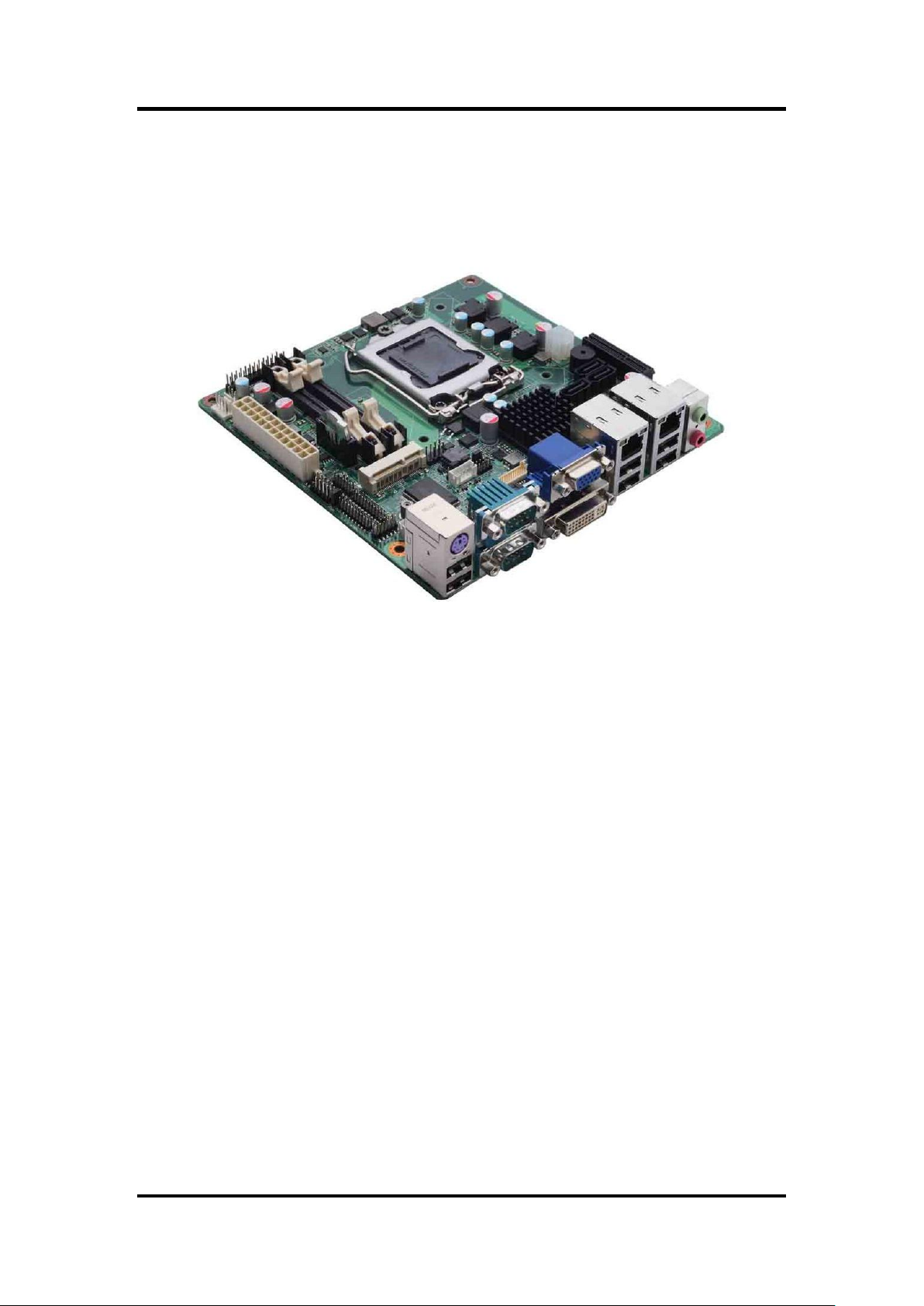
MANO861 Mini ITX Board
Chapter 1
Introduction
The MANO861 supports latest Intel® Desktop LGA1155 CPU-socket interface processor. Intel®
LGA1155 socket supports 22nm/32nm Intel® CoreTM i7 / CoreTM i5 / CoreTM i3 / Pentium
Celeron® desktop CPU, which are built on 22nm/32nm technologies to provide smart
performance and responsiveness on executing tasks. It combines the CPU and GPU to offer
fantastic HD media and graphics, especially on 3D gaming experience. Doubles the bandwidth
of your system memory up to 21GB/s and pumps up the system performance at lower power.
DMI (Direct Media Interface) architecture connects between the processor and chipset at
5.0Gb/s which twice the speed of previous version. The exceptionally increased interconnect
bit rate from 2.5Gb/s up to 5.0Gb/s would effectively eliminates the bottle neck of the system
performance and brings the most terrific computing experience from the present to the future.
There are 3 SATA ports 3.0Gb/s devices for backward compatibility.
®
1.1 Features
LGA1155 socket 3
2 DDR3 1333/1066MHz up to 16GB
1 PCI-Express x4
6 USB 2.0 supported
3 SATA 2.0 supported
6 COM ports supported
Dual view display
rd
Generation Intel® CoreTM i7 / i5 / i3 / Pentium® / Celeron
®
processors
/
Introduction 1
Page 10

MANO861 Mini ITX Board
1.2 Specifications
CPU
Intel
Intel
Intel
Intel
Intel
Intel
System Chipset
Intel
DRAM Transfer Rate
1333/1066MHz.
BIOS
AMI 32Mb SPI ROM.
System Memory
Two 204-pin unbuffered DDR3 SO-DIMM sockets.
Maximum up to 16GB DDR3 1333/1066MHz memory with two SO-DIMMs.
Onboard Multi I/O
Serial ports: One RS-232/422/485 (COM1) and five RS-232 (COM2~6).
One PS/2 keyboard/mouse.
Serial ATA
Three SATA 2.0 ports (3Gb/s performance).
USB Interface
Six USB 2.0 ports.
Display
One VGA
One DVI-D
One LVDS.
Ethernet
1
2
Audio
HD audio compliant (as MIC-in/line-out) via Realtek ALC892.
Digital I/O
Eight channels (four digital inputs and four digital outputs).
Expansion Interface
One PCI-Express x4 slot.
One PCI-Express Mini Card
Hardware Monitoring
Detect CPU/system temperature, voltage and fan speed.
®
CoreTM i7 processor.
®
CoreTM i7 processor.
®
CoreTM i5 processor.
®
CoreTM i3 processor.
®
Pentium
®
Celeron
®
H61.
st
port as 10/100/1000Mbps supports WOL, PXE with Realtek 8111E (LAN1).
nd
port as 10/100/1000Mbps supports WOL, PXE with Realtek 8111E (LAN2).
®
processor.
®
processor.
2 Introduction
Page 11

Note
All specifications and images are subject to change without notice.
Watchdog Timer
1~255 seconds; up to 256 levels.
Power Management
ACPI (Advanced Configuration and Power Interface).
Form Factor
Mini ITX form factor.
1.3 Utilities Supported
Chipset driver
Ethernet driver
Graphics driver
Audio driver
MANO861 Mini ITX Board
Introduction 3
Page 12

MANO861 Mini ITX Board
This page is intentionally left blank.
4 Introduction
Page 13
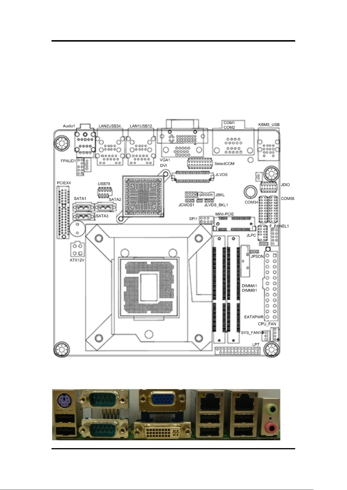
Board and Pin Assignments
2.1 Board Layout
MANO861 Mini ITX Board
Chapter 2
2.2 Rear Panel I/O
Board and Pin Assignments 5
Page 14
MANO861 Mini ITX Board
Jumper
Description
Setting
JCMOS1
Clear CMOS
Default: Normal Operation
1-2 close
JPSON
AT/ATX Power Mode Selection
Default: ATX Mode
2-3 close
JLVDS_BKL1
LVDS Backlight Power Selection
Default: +5V
1-2 close
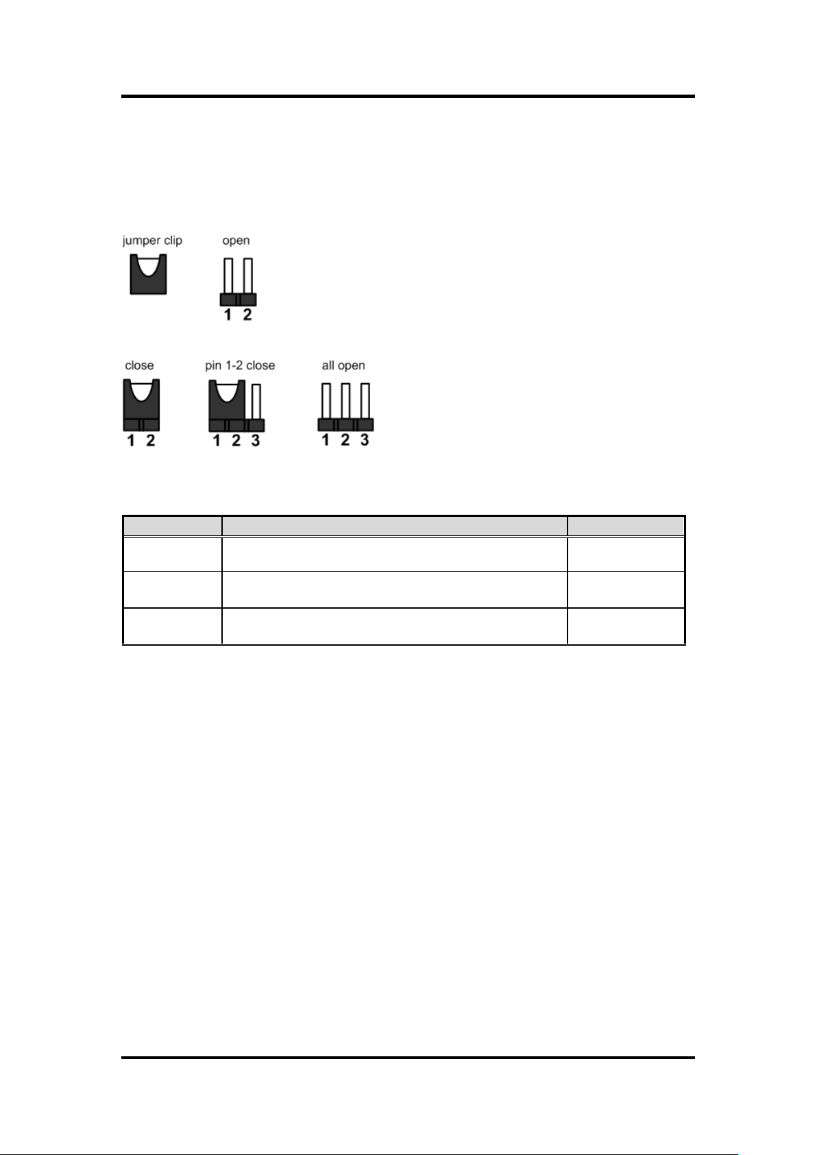
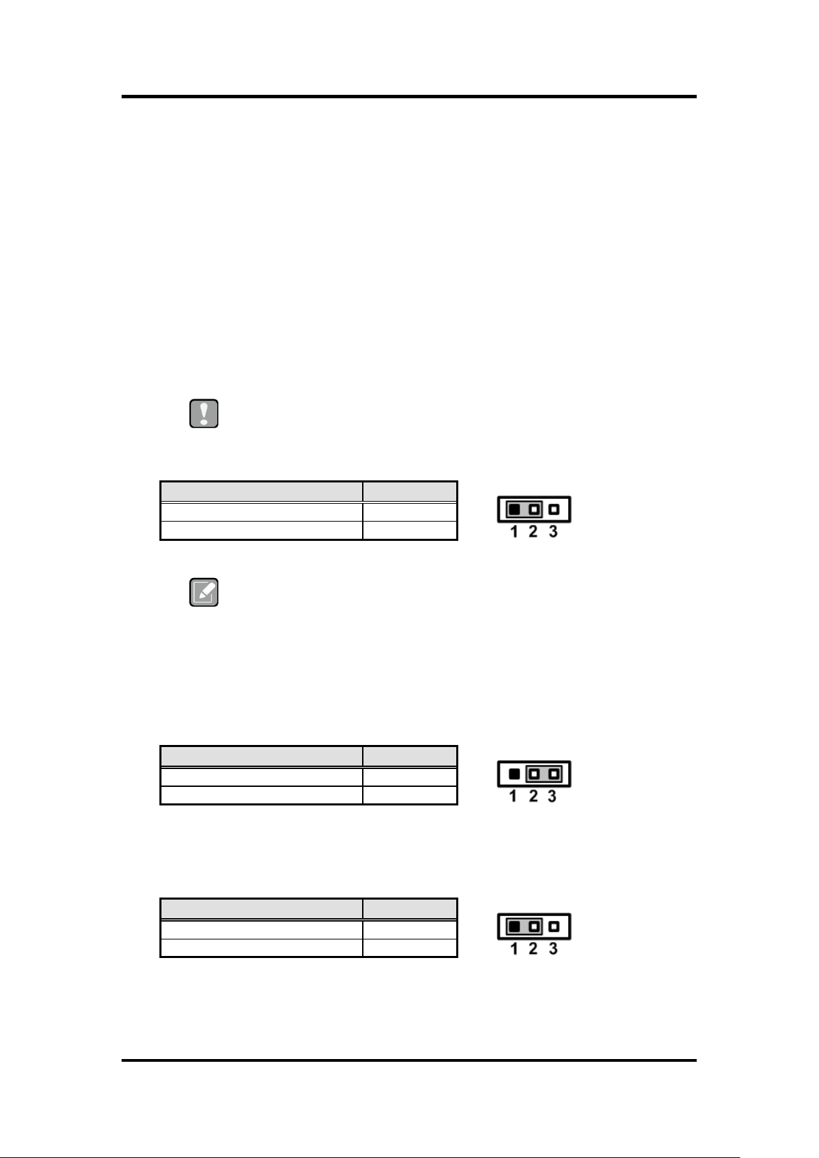
2.3 Jumper Settings
Jumper is a small component consisting of jumper clip and jumper pins. Install jumper clip on 2
jumper pins to close. And remove jumper clip from 2 jumper pins to open. The following
illustration shows how to set up jumper.
Before applying power to MANO861 Series, please make sure all of the jumpers are in factory
default position. Below you can find a summary table and onboard default settings.
6 Board and Pin Assignments
Page 15
MANO861 Mini ITX Board
Caution
Except when clearing the RTC RAM, never remove the cap on this jumper
default position. Removing the cap will cause system boot failure!
Note
You do not need to clear the RTC when the system hangs due to
overclocking. For system failure due to overclocking, use the C.P.R. (CPU
Parameter Recall) feature. Shut down and reboot the system so the BIOS
can automatically reset parameter settings to default values.
Function
Setting
Normal operation (Default)
1-2 close
Clear CMOS
2-3 close
Function
Setting
AT mode
1-2 close
ATX mode (Default)
2-3 close
Function
Setting
+5V (Default)
1-2 close
+3.3V
2-3 close
2.3.1 Clear CMOS (JCMOS1)
This jumper allows you to clear the Real Time Clock (RTC) RAM in CMOS. You can
clear the CMOS memory of date, time, and system setup parameters by erasing the
CMOS RTC RAM data. The onboard button cell battery powers the RAM data in CMOS,
which includes system setup information such as system passwords.
To erase the RTC RAM:
1. Turn OFF the computer and unplug the power cord.
2. Remove the onboard battery.
3. Move the jumper cap from pins 1-2 (default) to pins 2-3. Keep the cap on pins 2-3
for about 5~10 seconds, then move the cap back to pins 1-2.
4. Re-install the battery.
5. Plug the power cord and turn ON the computer.
6. Hold down the <Del> key during the boot process and enter BIOS setup to re-enter
data.
2.3.2 AT/ATX Power Mode Selection (JPSON)
This jumper allows you to select AT mode or ATX mode.
2.3.3 LVDS Backlight Power Selection (JLVDS_BKL1)
This jumper allows you to select LVDS backlight power.
Board and Pin Assignments 7
Page 16
MANO861 Mini ITX Board
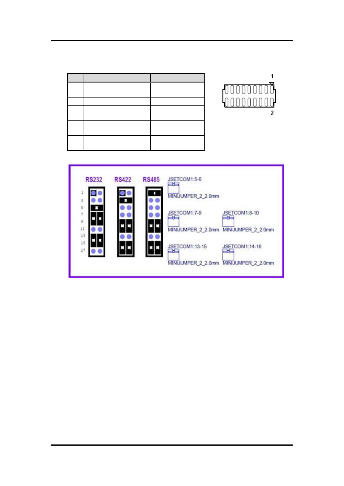
Pin
Signal
Pin
Signal
1
UART1_RXD
2
COM1_485_RXD
3
UART1_RXD
4
COM1_422_RXD
5
UART1_RXD
6
COM1_232_RXD
7
COM1_BUF_DCD#
8
COM1_BUF_TXD
9
COM1_DCD#
10
COM1_TXD
11
COM1_TXD422-
12
COM1_RXD422+
13
COM1_BUF_RXD
14
COM1_BUF_DTR#
15
COM1_RXD
16
COM1_DTR#
17
COM1_TXD422+
18
COM1_RXD422-
2.3.4 SelectCOM Connector (SelectCOM)
Select COM for RS-232/422/485.
8 Board and Pin Assignments
Page 17

MANO861 Mini ITX Board
Connector
Description
KBMS_USB
USB 2.0, PS/2 Keyboard and Mouse Connector
COM1~2
COM1 and COM2 Connector
DVI
DVI Port
VGA1
VGA Port
LAN1USB12
LAN1, USB 2.0 Port 1 and 2
LAN2USB34
LAN2, USB 2.0 Port 3 and 4
AUDIO1
Audio Jack
DIMMA1
204-pin DDR3 SO-DIMM Slot A1
DIMMB1
204-pin DDR3 SO-DIMM Slot B1
PCIEX4
PCI-Express x4 Slot
MINI-PCIE
PCI-Express Mini Card Connector
CPU_FAN
CPU Fan Connector
SYS_FAN1
System Fan Connector
COM3~6
COM3~COM6 Connectors
JDIO
GPIO Connector
F_PANEL1
Front Panel Connector
EATXPWR
EATX Power Connector
FPAUD1
Internal Audio Connector
JLVDS
LVDS Connector
JBKL
LCD Inverter Connector
SATA1~3
Serial ATA Connectors
ATX12V
ATX Power Connector
USB78
USB Connector
SelectCOM
SelectCOM Connector
SPI1
SPI Connector
JLPC
LPC Connector
LPT
LPT Connector
2.4 Connectors
Signals go to other parts of the system through connectors. Loose or improper connection
might cause problems, please make sure all connectors are properly and firmly connected.
Here is a summary table which shows all connectors on the hardware.
Board and Pin Assignments 9
Page 18
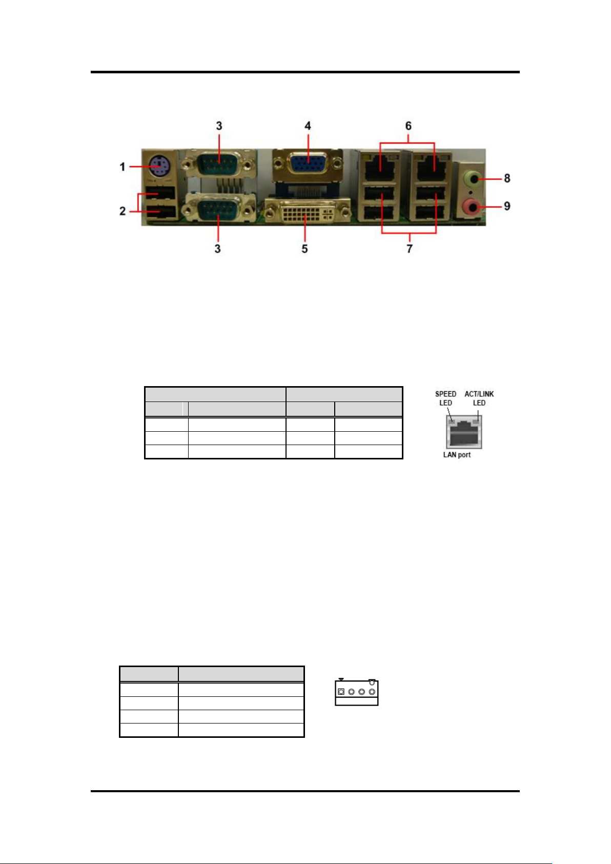
MANO861 Mini ITX Board
SPEED LED
ACT / LINK LED
Status
Description
Status
Description
OFF
10Mbps connection
OFF
No link
Orange
100Mbps connection
Green
Link
Green
1Gbps connection
Blinking
Data activity
Pin
Signal
1
GND
2
+12V
3
Tach
4
PWM
1
2.4.1 Rear Panel Connectors
1. PS/2 port (purple). This port is for a PS/2 keyboard and mouse.
2. USB 2.0 ports 5 and 6. These two 4-pin Universal Serial Bus (USB) ports are
available for connecting USB 2.0 devices.
3. Serial connectors. These 9-pin COM1 and COM2 ports are for serial devices.
4. VGA port. This 15-pin VGA port connects to a VGA monitor.
5. DVI-D port. This 29-pin DVI-D port is for a DVI monitor.
6. LAN (RJ-45) ports. Each of these ports allows Gigabit connection to a Local Area
Network (LAN) through a network hub. Refer to the table below for the LAN port
LED indications.
7. USB 2.0 ports 1~4. These four 4-pin Universal Serial Bus (USB) ports are
available for connecting USB 2.0 devices.
8. Line-out port (Green). This port connects a headphone or a speaker. In 4-channel,
6-channel, and 8-channel configuration, the function of this port becomes front
speaker-out.
9. Microphone port (pink). This port connects a microphone.
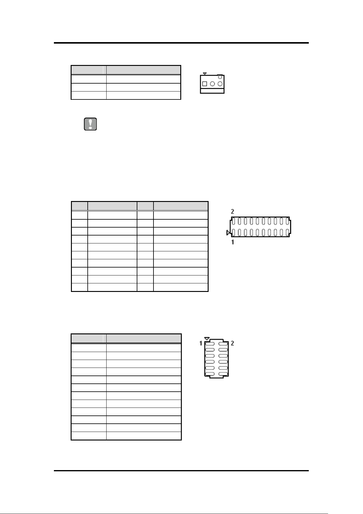
2.4.2 FAN Connectors (CPU_FAN and SYS_FAN1)
The fan connectors support cooling fans of 280mA (3.36 W max.) at 4800rpm or a total
of 1A~2.22A (26.64W max.) at +12V. Connect the fan cables to the fan connectors on
the motherboard, making sure that the black wire of each cable matches the ground pin
of the connector.
CPU fan interface is available through CPU_FAN, see table below.
10 Board and Pin Assignments
Page 19
Caution
Do not forget to connect the fan cables to the fan connectors. Insufficient
air flow inside the system may damage the motherboard components.
These are not jumpers! DO NOT place jumper caps on the fan connectors.
Pin
Signal
1
GND
2
SYSFAN1_VCC(PWM)
3
SYSFAN1_IO
Pin
Signal
Pin
Signal
1
DCD#
2
DSR#
3
RXD
4
RTS#
5
TXD
6
CTS#
7
DTR#
8
RI# 9 GND
10
GND
11
DCD#
12
DSR#
13
RXD
14
RTS#
15
TXD
16
CTS#
17
DTR#
18
RI#
19
GND
20
GND
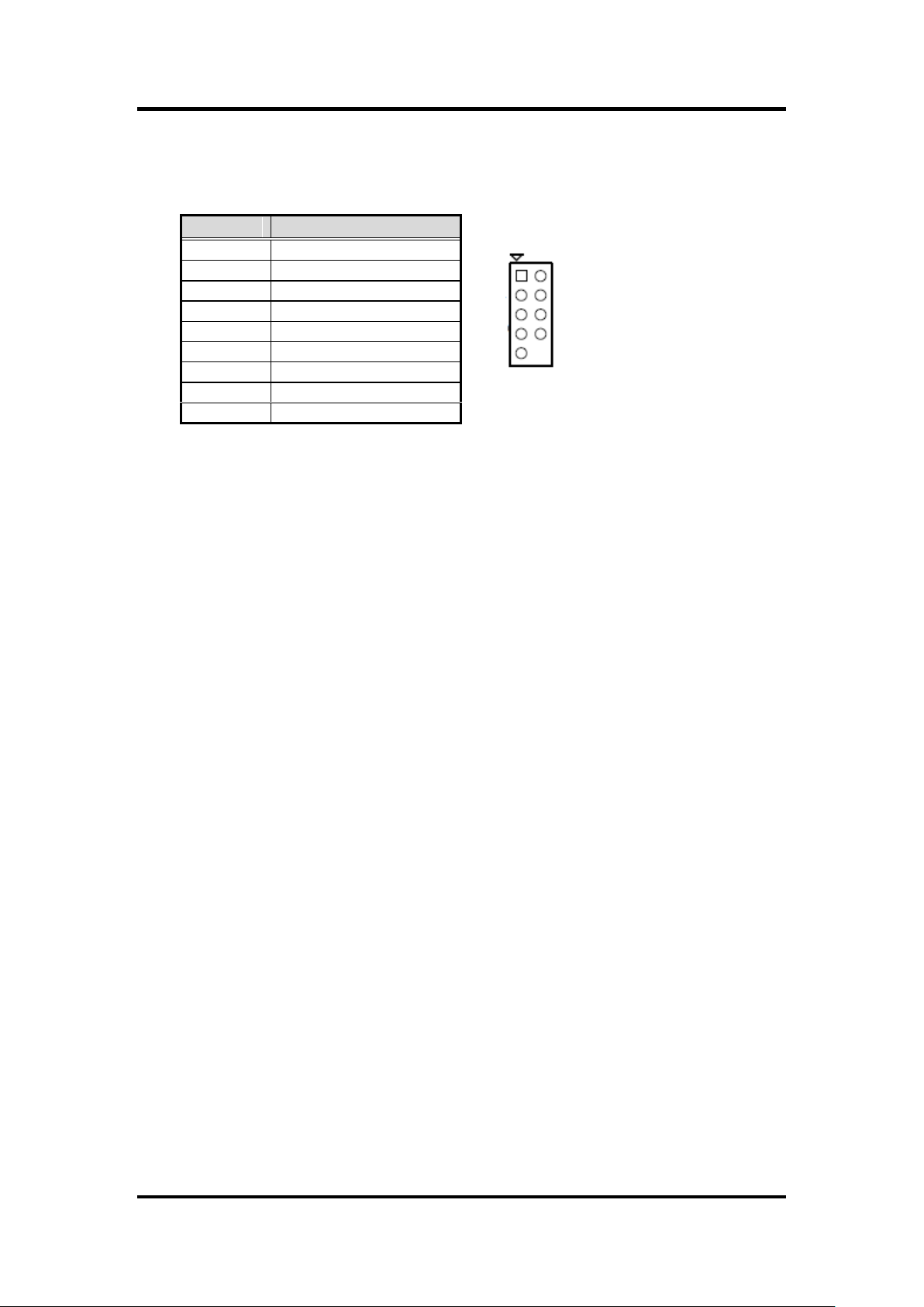
Pin
Signal
1
SIO_GPIO0
2
SIO_GPIO4
3
SIO_GPIO1
4
SIO_GPIO5
5
SIO_GPIO2
6
SIO_GPIO6
7
SIO_GPIO3
8
SIO_GPIO7
9
SMB_CLK_MAIN
10
SMB_DAT_MAIN
11
GND
12
VCC GPIO
System fan interface is available through SYS_FAN1, see table below.
1
MANO861 Mini ITX Board
2.4.3 COM Connectors (COM34 and COM56)
These connectors are for serial (COM) ports. Connect the serial port module cable to
this connector, then install the module to a slot opening at the back of the system
chassis.
COM34, COM56
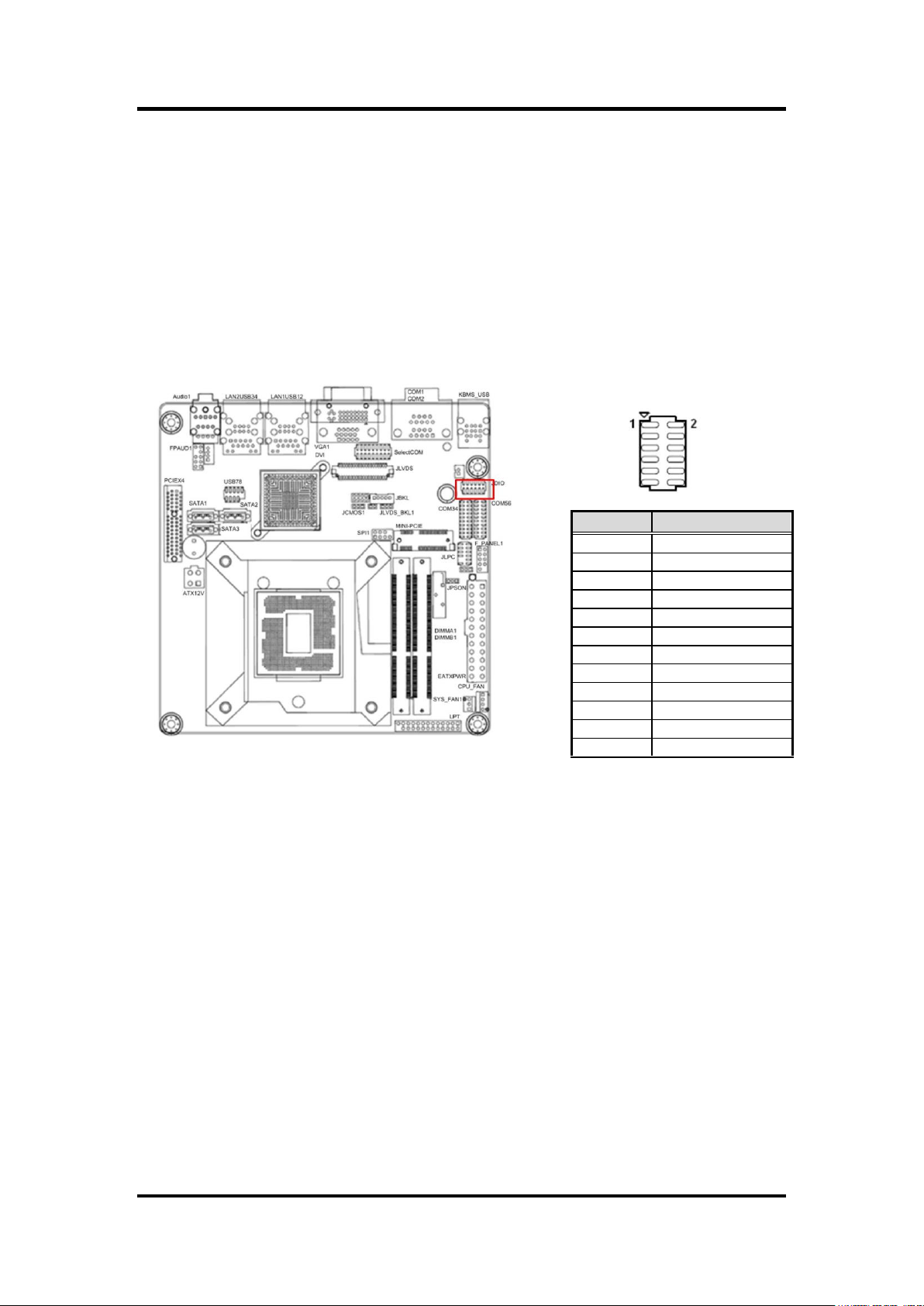
2.4.4 GPIO Connector (JDIO)
This connector is for GPIO function.
Board and Pin Assignments 11
Page 20
MANO861 Mini ITX Board
Pin
Signal
1
HDDLED+
2
POWERLED+-
3
HDDLED-
4
POWERLED-
5
GND
6
PWSWITCH
7
RESET
8
GND
9
NC
2.4.5 Front Panel Connector (F_PANEL1)
This connector is for a chassis-mounted front panel. The functions are described as
follows.
1
ATX Power Button/Soft-off Button (Pin 6-8 PWRBT)
This 2-pin connector is for the system power button. Pressing the power button turns the
system on or puts the system in sleep or soft-off mode depending on the BIOS settings.
Pressing the power switch and holding it for more than four seconds while the system is
ON turns the system OFF.
Reset Button (Pin 5-7 SYS_RST)
This 2-pin connector is for the chassis-mounted reset button for system reboot without
turning off the system power.
Power LED (Pin 2-4 PWRLED)
This 2-pin connector is for the system power LED. Connect the chassis power LED
cable to this connector. The system power LED lights up when you turn on the system
power, and blinks when the system is in sleep mode.
Hard Disk Drive Activity LED (Pin 1-3 HDLED)
This 2-pin connector is for the HDD Activity LED. Connect the HDD Activity LED cable to
this connector. The IDE LED lights up or flashes when data is read from or written to the
HDD.
12 Board and Pin Assignments
Page 21
MANO861 Mini ITX Board
Note
Use of a PSU with a higher power output is recommended when
configuring a system with more power-consuming devices. The
system may become unstable or may not boot up if the power is
inadequate.
Make sure that your power supply unit (PSU) can provide at least the
minimum power required by your system.
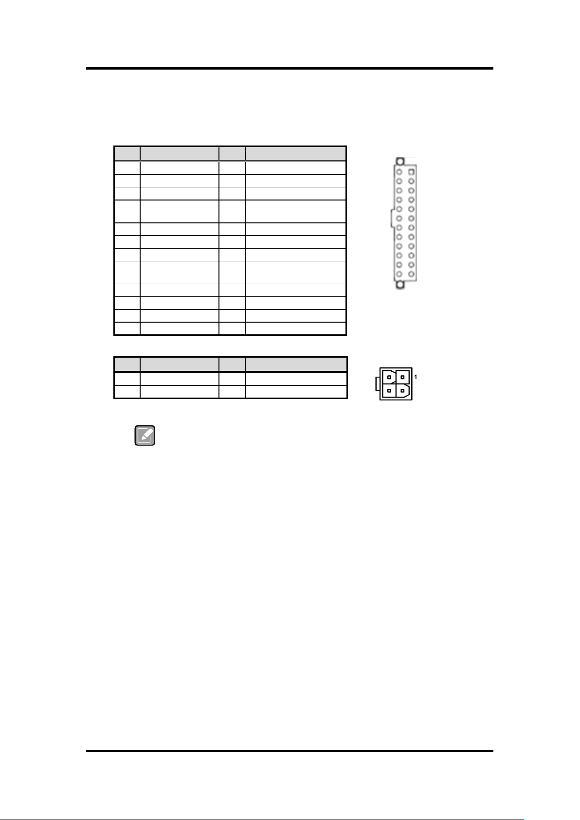
Pin
Signal
Pin
Signal
1
+3.3V
13
+3.3V
2
+3.3V
14
-12V
3
Ground
15
Ground
4
+5V
16
PS-ON# (power supply
remote on/off)
5
Ground
17
Ground
6
+5V
18
Ground
7
Ground
19
Ground
8
PWRGD (Power
Good)
20
No connect
9
+5V (Standby)
21
+5V
10
+12V
22
+5V
11
+12V
23
+5V
12
+3.3V
24
Ground
Pin
Signal
Pin
Signal
1
GND
3
+12V
2
GND
4
+12V
1
12
24
13
2.4.6 Power Connectors (EATXPWR and ATX12V)
Both connectors are for ATX power supply plugs. The power supply plugs are designed
to fit these connectors in only one orientation. Find the proper orientation and push down
firmly until the connectors completely fit.
EATXPWR
ATX12V
Board and Pin Assignments 13
Page 22
MANO861 Mini ITX Board
Important
For motherboards with the optional HD Audio feature, we recommend that
you connect a high-definition front panel audio module to this connector to
avail of the motherboard’s high‑definition audio capability.
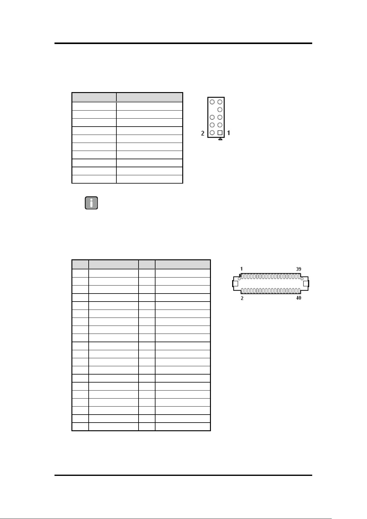
Pin
Signal
1
MIC2_L
2
GND
3
MIC2_R
4
PRESENSE
5
LIN2_R
6
MIC2_JD
7
FIO_SENSE
8
NC 9 LIN2_L
10
LINE_JD
Pin
Signal
Pin
Signal
1
VDD(+3.3V)
2
VDD(+5V)
3
VDD(+3.3V)
4
VDD(+5V)
5
I2C_CLK
6
I2C_DATA
7
GND
8
GND
9
LVDS_A1+
10
LVDS_A0+
11
LVDS_A1-
12
LVDS_A0-
13
GND
14
GND
15
LVDS_A3+
16
LVDS_A2+
17
LVDS_A3-
18
LVDS_A2-
19
GND
20
GND
21
LVDS_B1+
22
LVDS_B0+
23
LVDS_B1-
24
LVDS_B0-
25
GND
26
GND
27
LVDS_B3+
28
LVDS_B2+
29
LVDS_B3-
30
LVDS_B2-
31
GND
32
GND
33
LVDS_B_CK+
34
LVDS_A_CK+
35
LVDS_B_CK-
36
LVDS_A_CK-
37
GND
38
GND
39
VDD(+12V)
40
VDD(+12V)
2.4.7 Internal Audio Connector (FPAUD1)
This connector is for a chassis-mounted front panel audio I/O module that supports
either HD Audio or legacy AC ‘97 (optional) audio standard. Connect one end of the front
panel audio I/O module cable to this connector.
2.4.8 LVDS Connector (JLVDS)
The connector is for 24-bit dual channel LVDS panel.
14 Board and Pin Assignments
Page 23

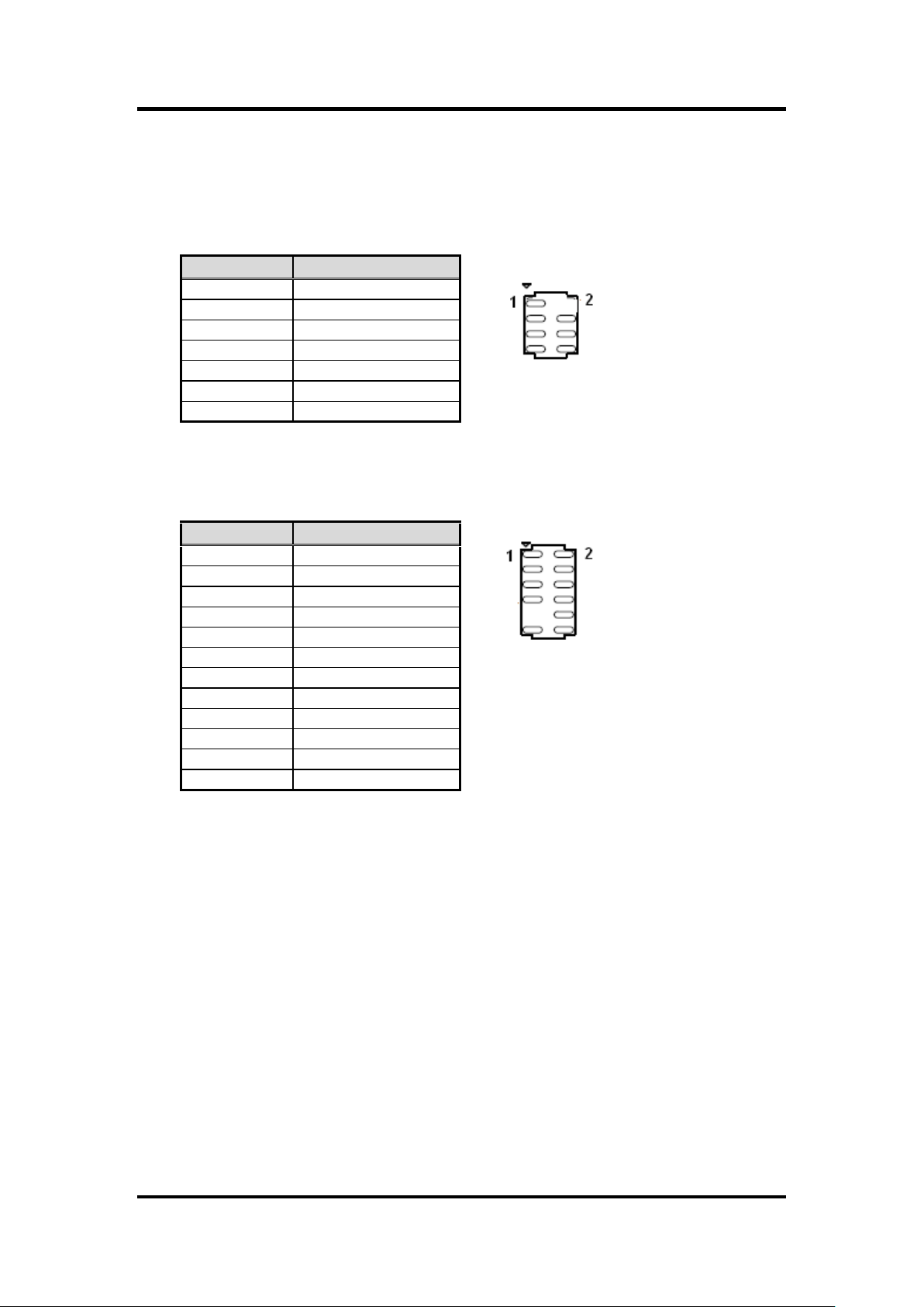
Pin
Signal
1
+12V
2
GND
3
BL_EN
4
BRIGHT1
5
+5V
Pin
Signal
1
GND
2
SATA_TXP2
3
SATA_TXN2
4
GND
5
SATA_RXN2
6
SATA_RXP2
7
GND
Pin
Signal
Pin
Signal
1
USB+5V
2
USB+5V
3
USB-
4
USB-
5
USB+
6
USB+
7
GND
8
GND
9
NC
2.4.9 LCD Inverter Connector (JBKL)
The connector is for the control of internal LVDS brightness.
MANO861 Mini ITX Board
1
2.4.10 Serial ATA Connectors (SATA1~SATA3)
These connectors support SATA 2.0 and are for the Serial ATA signal cables for Serial
ATA hard disk drives.
SATA1, SATA2, SATA3
2.4.11 USB Connector (USB78)
These connectors are for USB 2.0 ports. Connect the optional USB module cable to any
of these connectors, then install the module to a slot opening at the back of the system
chassis. These USB connectors comply with USB 2.0 specification that supports up to
480 Mbps connection speed.
Board and Pin Assignments 15
Page 24
MANO861 Mini ITX Board
Pin
Signal
1
+3V 2 GND
3
SPI_CS#
4
SPI_CLK
5
SPI_MISO
6
SPI_MOSI
7
SPI_HOLD#
Pin
Signal
1
NC
2
+3.3
3
LPC_AD3
4
PRST_SIO#
5
LPC_AD1
6
LPC_AD2
7
LPC_FRAME#
8
LPC_AD0
9 10
GND
11
CLK33M_LPC
12
GND
2.4.12 SPI Connector (SPI1)
Is a point-to-point interface standard, which allows network equipment designers to
develop an array of next-generation multi-service switches and routers to support
multi-service traffic with aggregate bandwidths up to OC-192 (10Gb/s) and beyond,
enabling them to dramatically increase system performance.
2.4.13 LPC Connector (JLPC)
16 Board and Pin Assignments
Page 25

Pin
Signal
Pin
Signal
1
STB#
2
AFD#
3
DATA0
4
ERR#
5
DATA1
6
INIT#
7
DATA2
8
SLIN#
9
DATA3
10
GND
11
DATA4
12
GND
13
DATA5
14
GND
15
DATA6
16
GND
17
DATA7
18
GND
19
ACK#
20
GND
21
BUSY
22
GND
23
PE
24
GND
25
SLCT
26
NC
2.4.14 LPT Connector (LPT)
MANO861 Mini ITX Board
Board and Pin Assignments 17
Page 26

MANO861 Mini ITX Board
This page is intentionally left blank.
18 Board and Pin Assignments
Page 27

MANO861 Mini ITX Board
Caution
Unplug the power cord from the wall socket before touching any component.
Use a grounded wrist strap or touch a safely grounded object or a metal
object, such as the power supply case, before handling components to avoid
damaging them due to static electricity.
Hold components by the edges to avoid touching the ICs on them.
Whenever you uninstall any component, place it on a grounded anti-static pad
or in the bag that came with the component.
Before you install or remove any component, ensure that the ATX power
supply is switched off or the power cord is detached from the power supply.
Failure to do so may cause severe damage to the motherboard, peripherals,
and/or components.
Warning
Make sure to unplug the power cord before installing or removing the
motherboard. Failure to do so can cause you physical injury and damage
motherboard components.
Caution
Do not over-tighten the screws! Doing so can damage the motherboard.
Chapter 3
Hardware Installation
Take note of the following precautions before you install motherboard components or change
any motherboard settings.
3.1 Motherboard Overview
Before you install the motherboard, study the configuration of your chassis to ensure that the
motherboard fits into it. Refer to the chassis documentation before installing the motherboard.
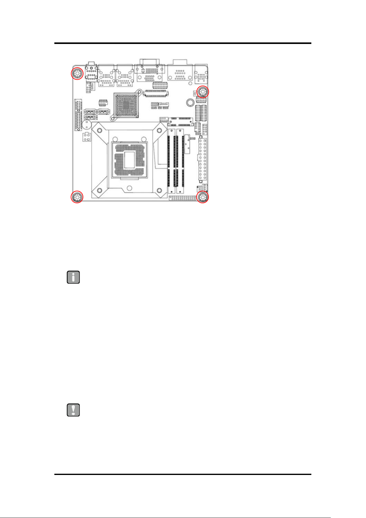
3.1.1 Placement Direction
When installing the motherboard, make sure that you place it into the chassis in the
correct orientation. The edge with external ports goes to the rear part of the chassis as
indicated in the image below.
3.1.2 Screw Holes
Place four (4) screws into the holes indicated by circles to secure the motherboard to the
chassis.
Hardware Installation 19
Page 28
MANO861 Mini ITX Board
Important
Your boxed Intel
®
Core™ i7/ i5/ i3 mobile processor package should come
with installation instructions for the CPU, fan and heatsink assembly. If the
instructions in this section do not match the CPU documentation, follow the
latter.
Upon purchase of the motherboard, make sure that the PnP cap is on the
socket and the socket pins are not bent. Contact your retailer immediately if
the PnP cap is missing, or if you see any damage to the PnP cap/socket
pins/motherboard components. Axiomtek will shoulder the cost of repair only
if the damage is shipment/transit-related.
Keep the cap after installing the motherboard. Axiomtek will process Return
Merchandise Authorization (RMA) requests only if the motherboard comes
with the cap on the LGA1155 socket.
The product warranty does not cover damage to the socket pins resulting
from incorrect CPU installation/removal, or misplacement/loss/incorrect
removal of the PnP cap.
Install the CPU fan and heatsink assembly before you install motherboard to
the chassis.
Caution
If you purchased a separate CPU heatsink and fan assembly, make sure that you
have properly applied Thermal Interface Material to the CPU heatsink or CPU
before you install the heatsink and fan assembly.
Place this side towards the rear of the chassis.
3.2 Central Processing Unit (CPU)
The motherboard comes with a surface mount Intel® LGA1155 socket supports 22nm/32nm
Intel® Core™ i7 / i5 / i3 / Pentium® / Celeron® processor in the LGA1155 package.
20 Hardware Installation
Page 29

MANO861 Mini ITX Board
Caution
Before installing the CPU, make sure that the socket box is facing
towards you and the load lever is on your left.
3.2.1 Installing the CPU
1. Locate the CPU socket on the motherboard.
2. Separate CPU cooler and its base first with screw driver.
3. Assemble the CPU fan retention module.
Hardware Installation 21
Page 30

MANO861 Mini ITX Board
Caution
The CPU fits in only one correct orientation. DO NOT force the CPU into
the socket to prevent bending the connectors on the socket and
damaging the CPU!
CPU socket triangle
Gold triangle
4. Position the CPU over the socket, making sure that the gold triangle is the same
side as CPU socket triangle.
5. Lock and unlock CPU.
22 Hardware Installation
Page 31

MANO861 Mini ITX Board
Important
Do not forget to connect the CPU fan connector! Hardware monitoring
errors can occur if you fail to plug this connector.
3.2.2 Installing the CPU Heatsink and Fan
1. Place the heatsink base on the relative bottom of motherboard.
2. Place the heatsink assembly on the top of the CPU, making sure that the four
fasteners match the holes on the motherboard.
3. Screw tightly the four fasteners.
4. Connect the CPU fan cable to the connector on the motherboard labeled
CPU_FAN.
Hardware Installation 23
Page 32
MANO861 Mini ITX Board
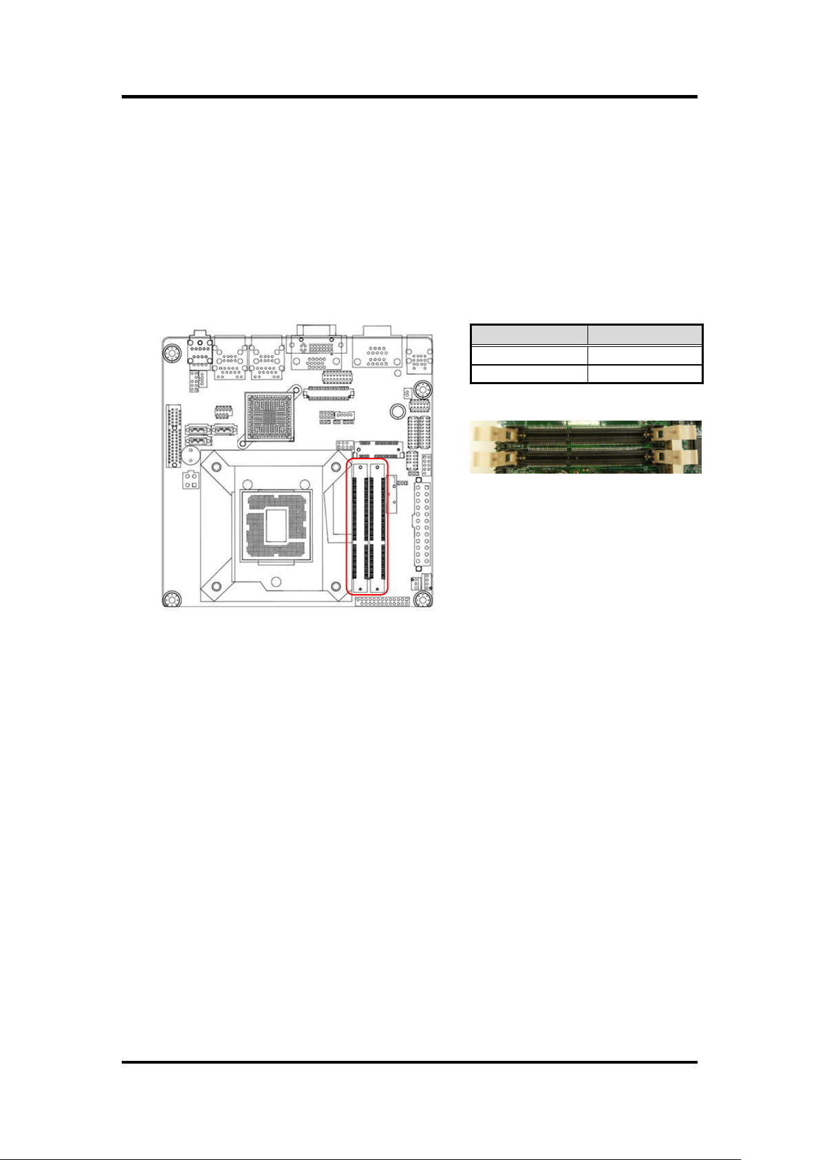
Channel
Slot
Channel A
DIMMA1
Channel B
DIMMB1
204-pin DDR3 SO-DIMM sockets
3.3 System Memory
3.3.1 Overview
The motherboard comes with two 204-pin Double Data Rate 3 (DDR3) Small Outline
Dual Inline Memory Modules (SO-DIMM) sockets.
A DDR3 module has the same physical dimensions as a DDR SO-DIMM but has a
204-pin footprint compared to the 204-pin DDR2 DIMM. DDR3 DIMMs are notched
differently to prevent installation on a DDR2 DIMM socket. The following figure illustrates
the location of the sockets:
24 Hardware Installation
Page 33

MANO861 Mini ITX Board
Important
IF you installed four 1GB memory modules, the system may detect
less than 3GB of total memory because of address space allocation
for other critical functions. This limitation applies to Windows XP
32-bit version operating system since it does not support PAE
(Physical Address Extension) mode.
IF you install Windows XP 32-bit version operating system, we
recommend that you install less than 3GB of total memory.
For dual channel configuration, the total size of memory module(s)
installed per channel must be the same for better performance
(DIMMA1=DIMMB1).
Always install SO-DIMMs with the same CAS latency. For optimum
compatibility, it is recommended that you obtain memory modules
from the same vendor.
Due to CPU limitation, SO-DIMM modules with 128Mb memory chips
or double-sided x16 memory chips are not supported in this
motherboard.
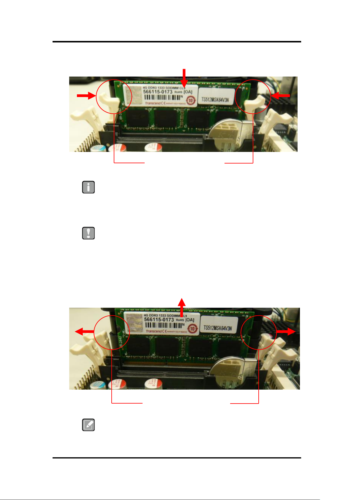
DDR3 SO-DIMM notch
Unlocked retaining clip
3.3.2 Memory Configurations
You may install 1GB, 2GB, and 4GB non-ECC DDR3 SO-DIMMs into the SO-DIMM
sockets using the memory configurations in this section.
3.3.3 Installing a SO-DIMM
1. Unlock a SO-DIMM socket by pressing the retaining clips outward.
2. Align a SO-DIMM on the socket such that the notch on the SO-DIMM matches the
break on the socket.
Hardware Installation 25
Page 34
MANO861 Mini ITX Board
Important
A DDR3 SO-DIMM is keyed with a notch so that it fits in only one
direction. DO NOT force a SO-DIMM into a socket to avoid damaging
the SO-DIMM.
The DDR3 SO-DIMM sockets do not support DDR2 SO-DIMMs. DO
NOT install DDR2 SO-DIMM to the DDR3 SO-DIMM socket.
Caution
Make sure to unplug the power supply before adding or removing
SO-DIMMs or other system components. Failure to do so may cause
severe damage to both the motherboard and the components.
Note
Support the SO-DIMM lightly with your fingers when pressing the
retaining clips. The SO-DIMM might get damaged when it flips out with
extra force.
Locked retaining clip
Unlocked retaining clip
3. Firmly insert the SO-DIMM into the socket until the retaining clips snap back in
place and the SO-DIMM is properly seated.
3.3.4 Removing a SO-DIMM
1. Simultaneously press the retaining clips downward to unlock the SO-DIMM.
2. Remove the SO-DIMM from the socket.
26 Hardware Installation
Page 35
MANO861 Mini ITX Board
Warning
Make sure to unplug the power cord before adding or removing expansion cards.
Failure to do so may cause you physical injury and damage motherboard
components.
3.4 Expansion Card
In the future, you may need to install expansion cards. The following sub-sections describe the
slots and the expansion cards that they support.
3.4.1 Installing an Expansion Card
1. Before installing the expansion card, read the documentation that came with it and
make the necessary hardware settings for the card.
2. Remove the system unit cover (if your motherboard is already installed in a
chassis).
3. Remove the bracket opposite the slot that you intend to use. Keep the screw for
later use.
4. Align the card connector with the slot and press firmly until the card is completely
seated on the slot.
5. Secure the card to the chassis with the screw you removed earlier.
6. Replace the system cover.
3.4.2 Configuring an Expansion Card
After installing the expansion card, configure it by adjusting the software settings.
1. Turn on the system and change the necessary BIOS settings, if any. See Chapter 5
for information on BIOS setup.
2. Assign an IRQ to the card if needed.
3. Install the software drivers for the expansion card.
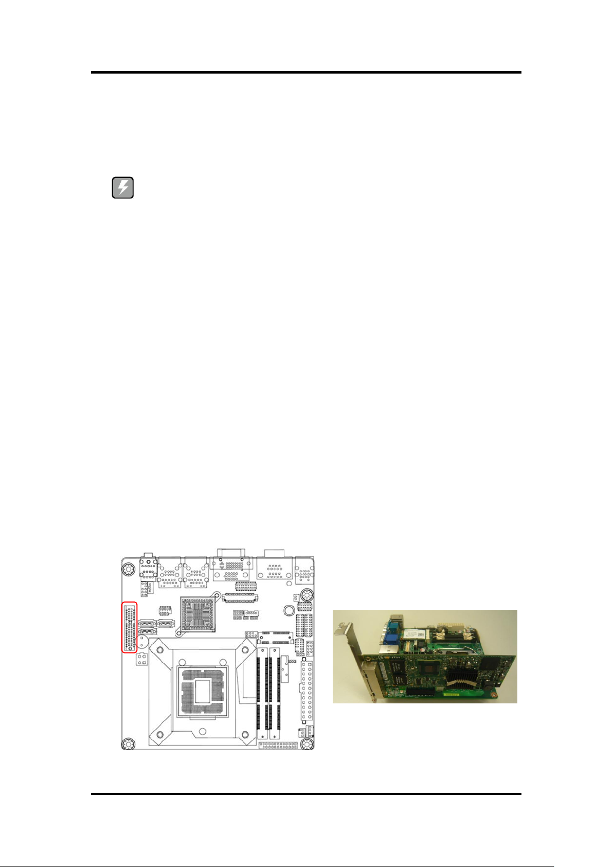
3.4.3 PCI-Express x4 Slot
This motherboard supports one PCI-Express x4. The following figure shows a graphics
card installed on the PCI-Express x4 slot.
Hardware Installation 27
Page 36

MANO861 Mini ITX Board
3.4.4 PCI-Express Mini Card Connector
This motherboard supports one PCI-Express Mini Card connector. The following figure
shows a Decode card installed on this connector.
28 Hardware Installation
Page 37

MANO861 Mini ITX Board
Chapter 4
Hardware Description
4.1 Microprocessors
The MANO861 Series supports Intel® CoreTM i7 / CoreTM i5 / CoreTM i3 / Pentium® / Celeron®
processors, which enable your system to operate under Windows® XP, Windows® 7 and Linux
environments. The system performance depends on the microprocessor. Make sure all correct
settings are arranged for your installed microprocessor to prevent the CPU from damages.
4.2 BIOS
The MANO861 Series uses AMI Plug and Play BIOS with a single 32Mbit SPI Flash.
4.3 System Memory
The MANO861 Series supports two 204-pin DDR3 SO-DIMM sockets for a maximum memory
of 16GB DDR3 SDRAMs. The memory module comes in sizes of 1GB, 2GB and 4GB.
Hardware Description 29
Page 38

MANO861 Mini ITX Board
4.4 I/O Port Address Map
The Intel® CoreTM i7 / CoreTM i5 / CoreTM i3 / Pentium® / Celeron® processors communicate via
I/O ports. Total 1KB port addresses are available for assigning to other devices via I/O
expansion cards.
30 Hardware Description
Page 39

MANO861 Mini ITX Board
Hardware Description 31
Page 40
MANO861 Mini ITX Board
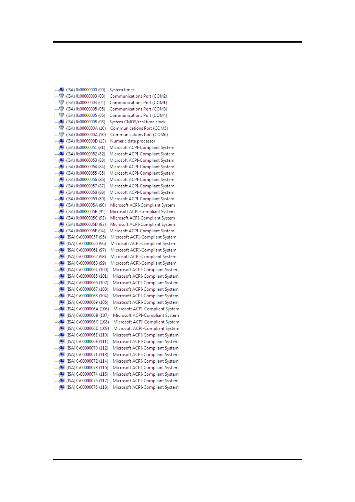
4.5 Interrupt Controller (IRQ) Map
The interrupt controller (IRQ) mapping list is shown as follows:
32 Hardware Description
Page 41

MANO861 Mini ITX Board
Hardware Description 33
Page 42

MANO861 Mini ITX Board
34 Hardware Description
Page 43

4.6 Memory Map
The memory mapping list is shown as follows:
MANO861 Mini ITX Board
Hardware Description 35
Page 44

MANO861 Mini ITX Board
This page is intentionally left blank.
36 Hardware Description
Page 45

MANO861 Mini ITX Board
Note
Some of the navigation keys differ from one screen to another.
Chapter 5
AMI BIOS Setup Utility
The AMI UEFI BIOS provides users with a built-in setup program to modify basic system
configuration. All configured parameters are stored in a flash chip to save the setup information
whenever the power is turned off. This chapter provides users with detailed description about
how to set up basic system configuration through the AMI BIOS setup utility.
5.1 Starting
To enter the setup screens, follow the steps below:
1. Turn on the computer and press the <Del> key immediately.
2. After you press the <Del> key, the main BIOS setup menu displays. You can access the
other setup screens from the main BIOS setup menu, such as the Advanced and Chipset
menus.
It is strongly recommended that you should avoid changing the chipset’s defaults. Both AMI
and your system manufacturer have carefully set up these defaults that provide the best
performance and reliability.
5.2 Navigation Keys
The BIOS setup/utility uses a key-based navigation system called hot keys. Most of the BIOS
setup utility hot keys can be used at any time during the setup navigation process. These keys
include <F1>, <F2>, <Enter>, <ESC>, <Arrow> keys, and so on.
AMI BIOS Setup Utility 37
Page 46

MANO861 Mini ITX Board
Hot Keys
Description
Left/Right
The Left and Right <Arrow> keys allow you to select a setup screen.
Up/Down
The Up and Down <Arrow> keys allow you to select a setup screen or
sub-screen.
+ Plus/Minus
The Plus and Minus <Arrow> keys allow you to change the field value of a
particular setup item.
Tab
The <Tab> key allows you to select setup fields.
F1
The <F1> key allows you to display the General Help screen.
F2
The <F2> key allows you to Load Previous Values.
F3
The <F3> key allows you to Load Optimized Defaults.
F4
The <F4> key allows you to save any changes you have made and exit
Setup. Press the <F4> key to save your changes.
Esc
The <Esc> key allows you to discard any changes you have made and exit
the Setup. Press the <Esc> key to exit the setup without saving your
changes.
Enter
The <Enter> key allows you to display or change the setup option listed for a
particular setup item. The <Enter> key can also allow you to display the
setup sub- screens.
38 AMI BIOS Setup Utility
Page 47
MANO861 Mini ITX Board
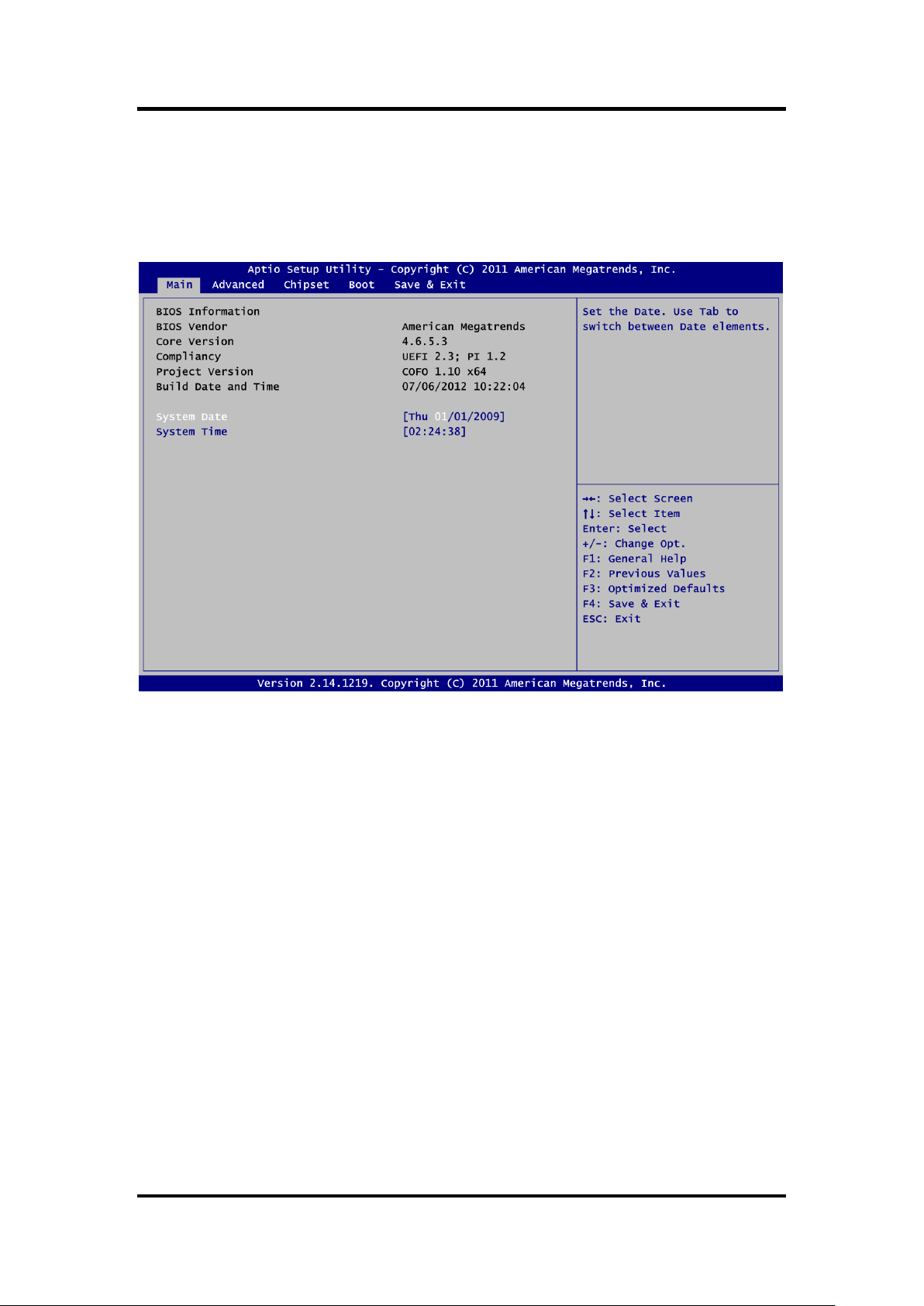
5.3 Main Menu
When you first enter the setup utility, you will enter the Main setup screen. You can always
return to the Main setup screen by selecting the Main tab. System Time/Date can be set up as
described below. The Main BIOS setup screen is shown below.
BIOS Information
Display the auto-detected BIOS information.
System Date/Time
Use this option to change the system time and date. Highlight System Time or System Date
using the <Arrow> keys. Enter new values through the keyboard. Press the <Tab> key or the
<Arrow> keys to move between fields. The date must be entered in MM/DD/YY format. The
time is entered in HH:MM:SS format.
AMI BIOS Setup Utility 39
Page 48

MANO861 Mini ITX Board
Caution
Take caution when changing the settings of the Advanced menu items. Incorrect
field values can cause the system to malfunction.
5.4 Advanced Menu
The Advanced menu also allows users to set configuration of the CPU and other system
devices. You can select any of the items in the left frame of the screen to go to the sub menus:
► ACPI Settings
► CPU Configuration
► SATA Configuration
► PCH-FW Configuration
► USB Configuration
► Second Super IO Configuration
► Super IO Configuration
► H/W Monitor
► Option Rom Policy
► CPU PPM Configuration
For items marked with “”, please press <Enter> for more options.
40 AMI BIOS Setup Utility
Page 49

MANO861 Mini ITX Board
ACPI Settings
You can use this screen to select options for the ACPI configuration, and change the value
of the selected option. A description of the selected item appears on the right side of the
screen.
ACPI Sleep State
Select the highest ACPI sleep state the system will enter when the suspend button is
pressed. Configuration options are Suspend Disabled, S1 only (CPU Stop Clock), and S3
only (Suspend to RAM).
To correctly support wake by use of USB from the S3 system power state, please refer to
the following Microsoft’s link:
http://support.microsoft.com/kb/841858/en-us
S3 Video Repost
Enable or disable video repost.
Resume On RTC Alarm
Enable or disable system wake on alarm even. When enabled, system will wake upon the
hr/min/sec specified.
Wake On PCIE#
Enable or disable PCIE to generate a wake event.
AMI BIOS Setup Utility 41
Page 50
MANO861 Mini ITX Board
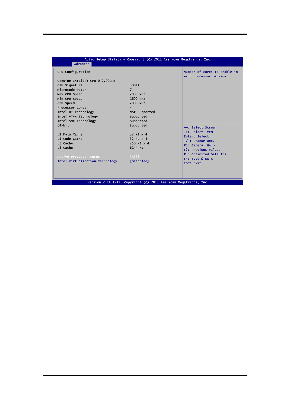
CPU Configuration
This screen shows the CPU information.
Active Processor Cores
Allow users to set how many processor cores should be active.
Intel Virtualization Technology
This item allows a hardware platform to run multiple operating systems separately and
simultaneously, enabling one system to virtually function as several systems.
42 AMI BIOS Setup Utility
Page 51

MANO861 Mini ITX Board
SATA Configuration
In this Configuration menu, you can see the currently installed hardware in the SATA ports.
During system boot up, the BIOS automatically detects the presence of SATA devices.
SATA Controller(s)
Enable or disable SATA device.
SATA Mode Selection
Determine how SATA controller(s) operate. Operation mode options are: IDE Mode, AHCI
Mode and RAID Mode.
AMI BIOS Setup Utility 43
Page 52

MANO861 Mini ITX Board
PCH-FW Configuration
This screen displays Management Engine (ME) Firmware information.
44 AMI BIOS Setup Utility
Page 53

MANO861 Mini ITX Board
USB Configuration
You can use this screen to select options for the USB Configuration, and change the value
of the selected option. A description of the selected item appears on the right side of the
screen.
USB Devices
Display all detected USB devices.
Legacy USB Support
Use this item to enable or disable support for USB device on legacy operating system. The
default setting is Enabled. Auto option disables legacy support if no USB devices are
connected. Disable option will keep USB devices available only for EFI applications.
AMI BIOS Setup Utility 45
Page 54

MANO861 Mini ITX Board
Second Super IO Configuration
You can use this screen to select options for the Second Super IO Configuration, and
change the value of the selected option. A description of the selected item appears on the
right side of the screen. For items marked with “”, please press <Enter> for more
options.
Serial Port 3~6 Configuration
Use these items to set parameters of serial port 3~6.
46 AMI BIOS Setup Utility
Page 55

MANO861 Mini ITX Board
Super IO Configuration
You can use this screen to select options for the Super IO Configuration, and change the
value of the selected option. A description of the selected item appears on the right side of
the screen. For items marked with “”, please press <Enter> for more options.
Serial Port 1~2 Configuration
Use these items to set parameters of serial port 1~2.
Parallel Port Configuration
Use this item to set parameters of parallel port.
Watch Dog Timer
Enable or disable watchdog timer function.
Chassis Opened Warning
Enable or disable chassis opened warning setting.
AMI BIOS Setup Utility 47
Page 56

MANO861 Mini ITX Board
H/W Monitor
Use this screen for Smart Fan configuration and hardware health status monitoring.
This screen displays the temperature of system and CPU, cooling fan speed in RPM and
system voltages (VCORE, +12V, +5V, 5VSB, etc).
Smart Fan
This option allows users to configure Smart Fan function.
48 AMI BIOS Setup Utility
Page 57

Option Rom Policy
MANO861 Mini ITX Board
Boot Option Filter
This option controls what devices system can boot to.
Launch PXE OpROM policy
Enable or disable boot options for legacy network devices.
Launch Storage OpROM policy
Control the execution of UEFI and legacy storage OpROM.
AMI BIOS Setup Utility 49
Page 58

MANO861 Mini ITX Board
CPU PPM Configuration
Use this screen for CPU PPM configuration.
EIST
Enable or disable Intel® SpeedStep. When enabled, CPU speed is controlled by the
operating system. When disabled, CPU runs at its default speed.
Turbo Mode
This item is for enabling or disabling turbo mode. When enabled, it allows processor cores
to run faster than marked frequency under certain conditions.
CPU C3 Report
Enable or disable CPU C3 report to the operating system.
CPU C6 Report
Enable or disable CPU C6 report to the operating system.
50 AMI BIOS Setup Utility
Page 59

MANO861 Mini ITX Board
5.5 Chipset Menu
The Chipset menu allows users to change the advanced chipset settings. You can select any
of the items in the left frame of the screen to go to the sub menus:
► PCH-IO Configuration
► System Agent (SA) Configuration
For items marked with “”, please press <Enter> for more options.
AMI BIOS Setup Utility 51
Page 60
MANO861 Mini ITX Board
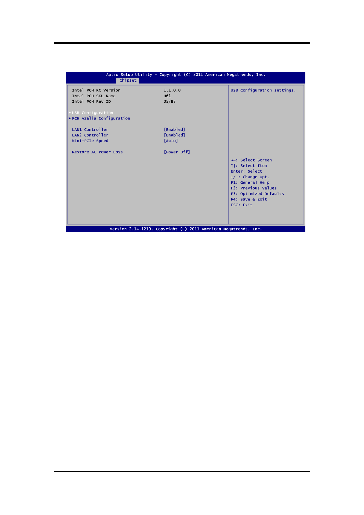
PCH-IO Configuration
This screen allows users to set PCH parameters.
USB Configuration
USB configuration settings.
PCH Azalia Configuration
PCH Azalia device configuration settings.
LAN1 Controller
Enable or disable LAN1 controller.
LAN2 Controller
Enable or disable LAN2 controller.
Mini-PCIe Speed
Allow you to select mini PCI-Express speed.
Restore AC Power Loss
Set the system power status when power returns from a power failure situation. The
system power status options are Power Off, Power On and Last State.
52 AMI BIOS Setup Utility
Page 61

PCH USB Configuration
MANO861 Mini ITX Board
EHCI1/EHCI2
Enable or disable the EHCI controller.
USB Ports Per-Port Disable Control
Enable or disable each USB port individually.
AMI BIOS Setup Utility 53
Page 62

MANO861 Mini ITX Board
PCH Azalia Configuration
Azalia
Control detection of the Azalia device. Configuration options are Disabled, Enabled and
Auto.
54 AMI BIOS Setup Utility
Page 63

MANO861 Mini ITX Board
System Agent (SA) Configuration
This screen shows System Agent information and provides function for specifying related
parameters. For items marked with “”, please press <Enter> for more options.
VT-d
Enable or disable Intel® chipset virtualization technology for directed I/O. VT-d can help
end users improve security and reliability of the systems and also improve performance of
I/O devices in virtualized environment.
AMI BIOS Setup Utility 55
Page 64
MANO861 Mini ITX Board
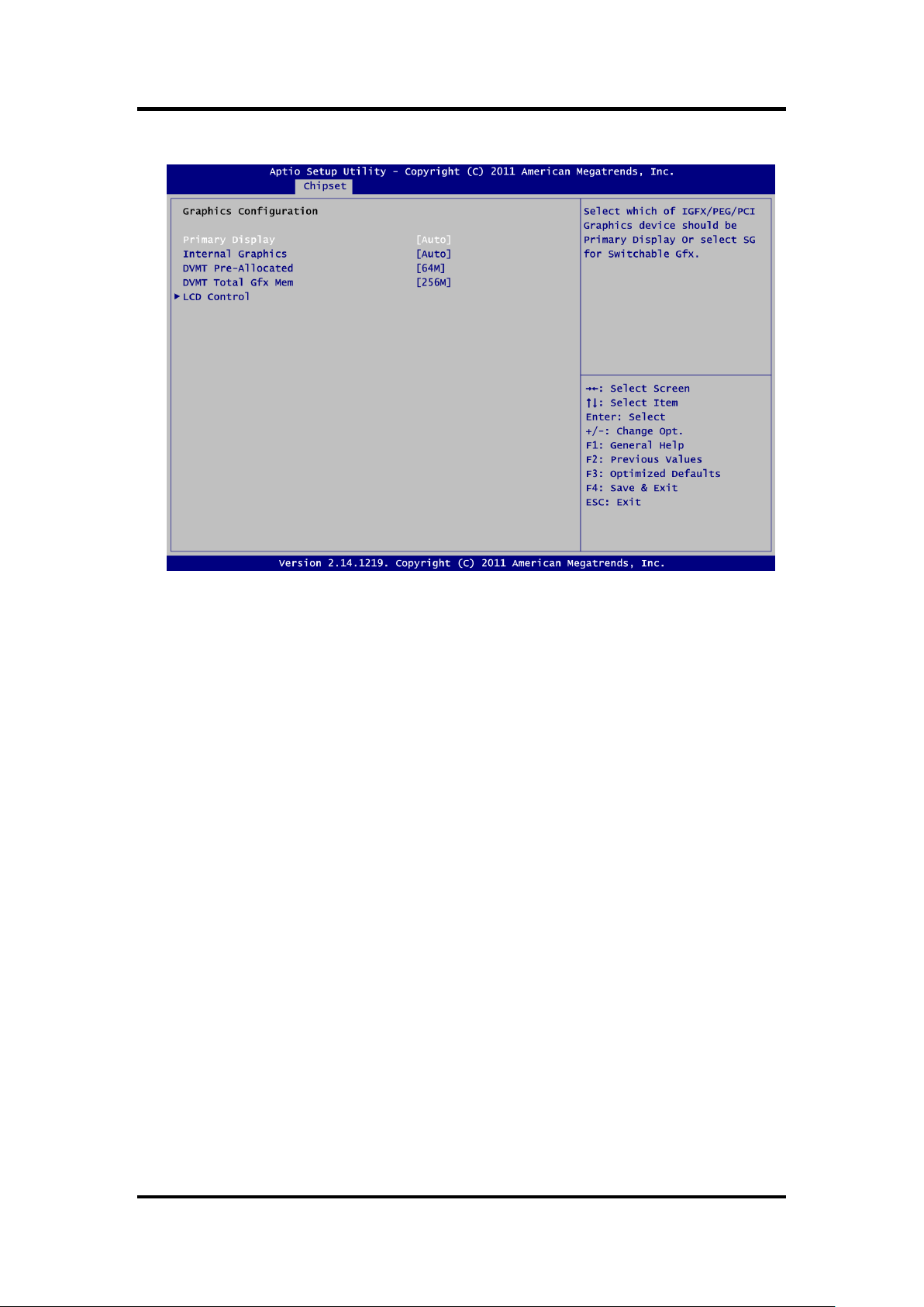
Graphics Configuration
Primary Display
Allow you to select which graphics controller to use as the primary boot device.
Internal Graphics
Enable or disable IGD.
DVMT Pre-Allocated
Select DVMT pre-allocated memory size.
DVMT Total Gfx Mem
Select DVMT total memory size.
56 AMI BIOS Setup Utility
Page 65

NB PCIe Configuration
MANO861 Mini ITX Board
PEG0 – Gen X
Select PEG0 speed.
PEG0 ASPM
Control ASPM support for the PEG device.
Enable PEG
Enable or disable PEG always.
Detect Non-Compliance Device
Enable or disable the detection of a non-compliance PCI-Express device in PEG.
AMI BIOS Setup Utility 57
Page 66
MANO861 Mini ITX Board
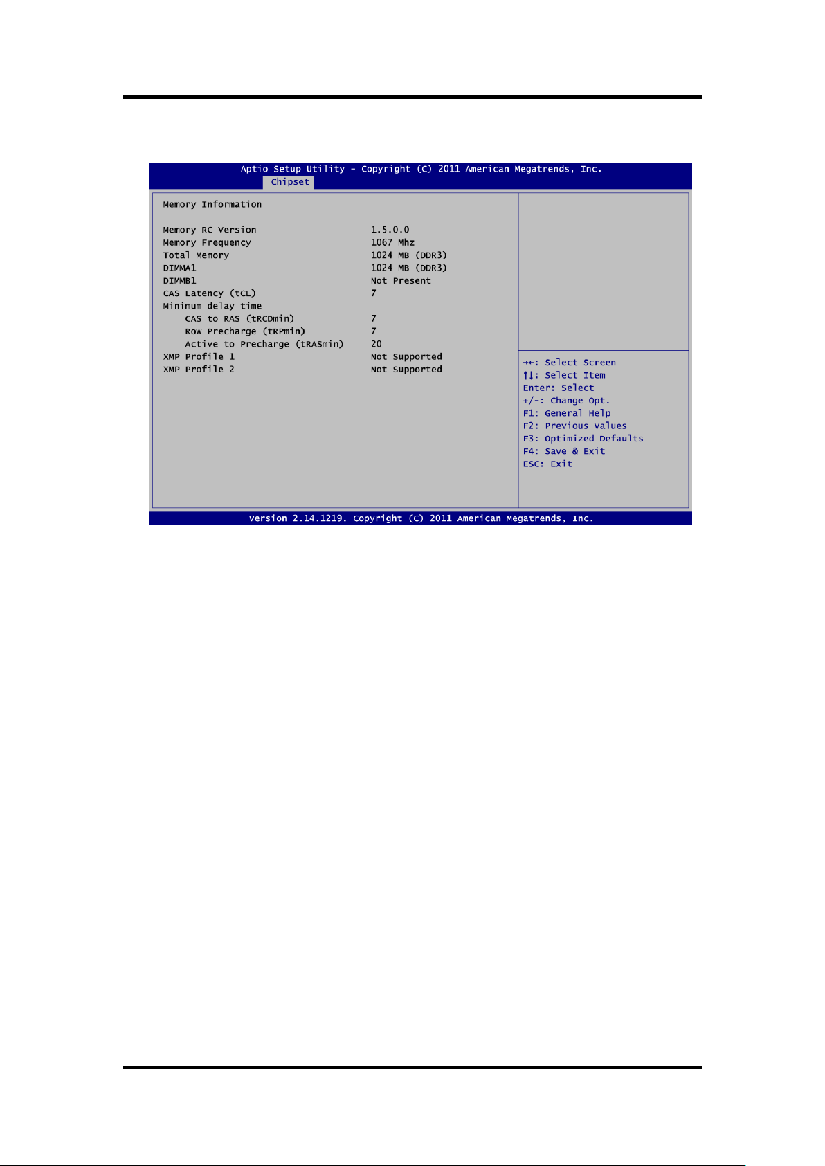
Memory Configuration
This screen displays system memory information.
58 AMI BIOS Setup Utility
Page 67
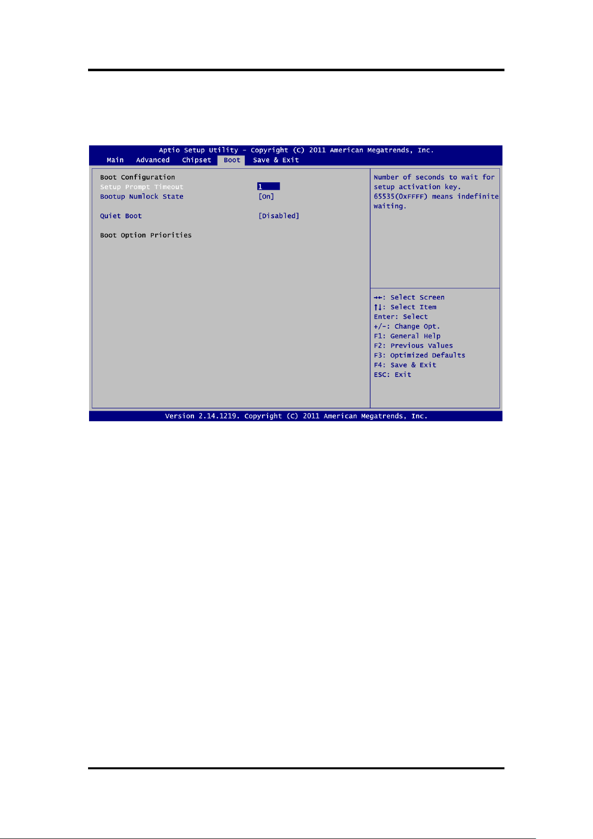
5.6 Boot Menu
The Boot menu allows users to change boot options of the system.
MANO861 Mini ITX Board
Setup Prompt Timeout
Number of seconds to wait for setup activation key. 65535(0xFFFF) means indefinite
waiting.
Bootup NumLock State
Use this item to select the power-on state for the keyboard NumLock.
Quiet Boot
Select to display either POST output messages or a splash screen during boot-up.
Boot Option Priorities
These are settings for boot priority. Specify the boot device priority sequence from the
available devices.
AMI BIOS Setup Utility 59
Page 68
MANO861 Mini ITX Board
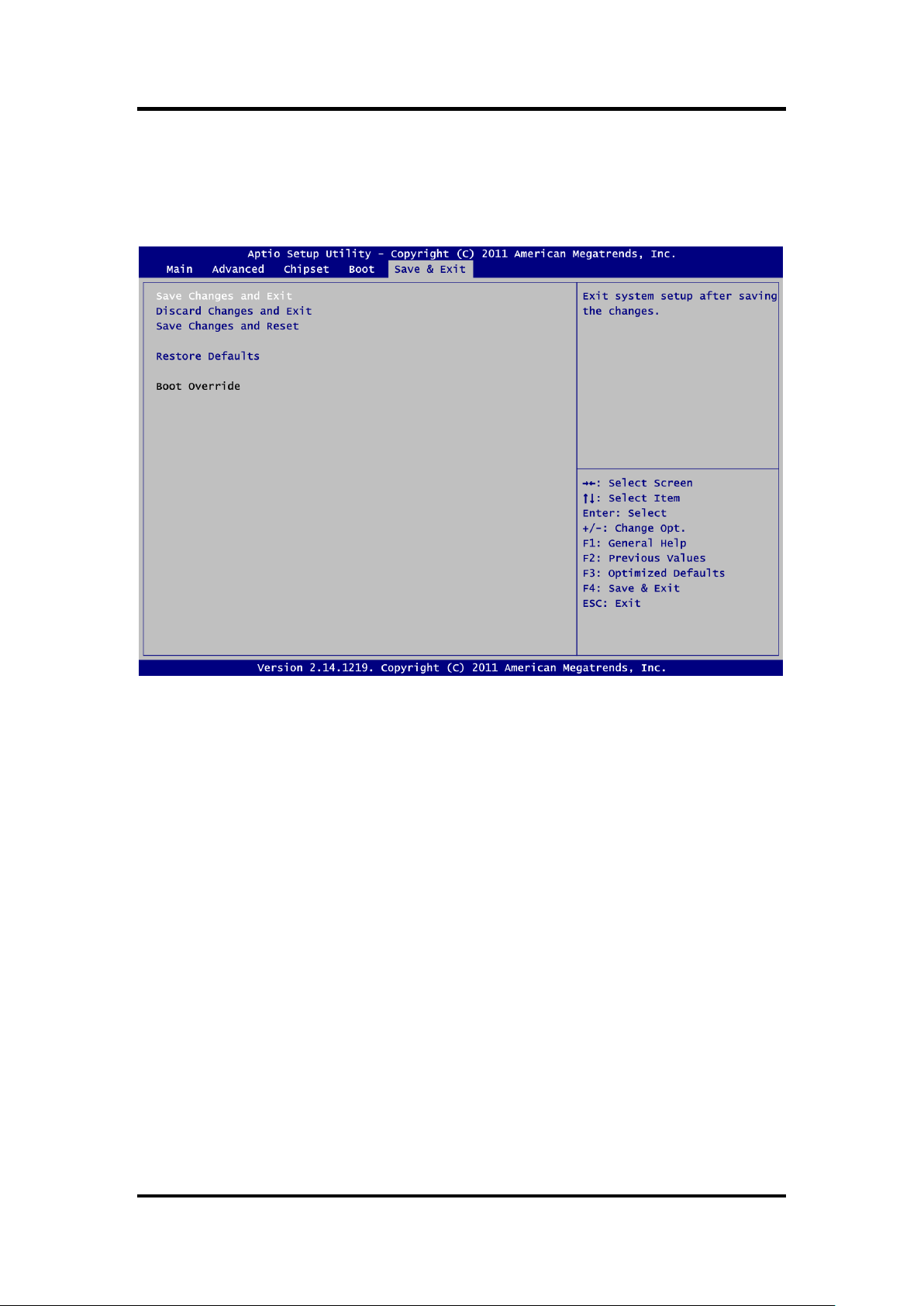
5.7 Save & Exit Menu
The Save & Exit menu allows users to load your system configuration with optimal or fail-safe
default values.
Save Changes and Exit
When you have completed the system configuration changes, select this option to leave
Setup and return to Main Menu. Select Save Changes and Exit from the Save & Exit menu
and press <Enter>. Select Yes to save changes and exit.
Discard Changes and Exit
Select this option to quit Setup without making any permanent changes to the system
configuration and return to Main Menu. Select Discard Changes and Exit from the Save &
Exit menu and press <Enter>. Select Yes to discard changes and exit.
Save Changes and Reset
When you have completed the system configuration changes, select this option to leave
Setup and reboot the computer so the new system configuration parameters can take
effect. Select Save Changes and Reset from the Save & Exit menu and press <Enter>.
Select Yes to save changes and reset.
Restore Defaults
It automatically sets all Setup options to a complete set of default settings when you select
this option. Select Restore Defaults from the Save & Exit menu and press <Enter>.
Boot Override
Select a drive to immediately boot that device regardless of the current boot order.
60 AMI BIOS Setup Utility
Page 69

MANO861 Mini ITX Board
Begin
Enable and Initialize
Watchdog Timer
Program “A”
Disable Watchdog
Timer
Next
Next
Next
Next
Begin
Enable and Initialize
Watchdog Timer
Program “A”
Reset Watchdog
Timer
Next
Next
Next
Next
Appendix A
Watchdog Timer
About Watchdog Timer
Software stability is major issue in most application. Some embedded systems are not
watched by human for 24 hours. It is usually too slow to wait for someone to reboot when
computer hangs. The systems need to be able to reset automatically when things go wrong.
The watchdog timer gives us solution.
The watchdog timer is a counter that triggers a system reset when it counts down to zero from
a preset value. The software starts counter with an initial value and must reset it periodically. If
the counter ever reaches zero which means the software has crashed, the system will reboot.
The integrated watchdog timer can be set up by programming. There are 1~255 levels
available.
How to Use Watchdog Timer
Assume that program A needs to keep running in a system. The value of watchdog timer must
be set bigger than the running time of program A. Then, after the running time of program A is
finished, either to disable or to reset watchdog timer.
When program A has problems that cause system shut down, the system can be rebooted by
watchdog timer when the value of watchdog timer has counted down to 0.
Watchdog Timer 61
Page 70

MANO861 Mini ITX Board
Sample Program
Assembly sample code :
#define NCT6776F_CONFIG_INDEX 0x2e
#define NCT6776F_CONFIG_DATA 0x2f
#define NCT6776F_CONFIG_MODE_ENTER_VALUE 0x87
#define NCT6776F_CONFIG_MODE_EXIT_VALUE 0xAA
#define NCT6776F_LDN_SEL_REGISTER 0x07
#define NCT6776F_ACTIVATE_REGISTER 0x30
#define NCT6776F_LDN_GPIO3 0x09
#define NCT6776F_LDN_WDT 0x08
#ifdef Oem_NCT6776F_WDT_PRESENT
#if Oem_NCT6776F_WDT_PRESENT
UINT8 Data8=0;
IoWrite8(NCT6776F_CONFIG_INDEX, NCT6776F_CONFIG_MODE_ENTER_VALUE);
IoWrite8(NCT6776F_CONFIG_INDEX, NCT6776F_CONFIG_MODE_ENTER_VALUE);
IoWrite8(NCT6776F_CONFIG_INDEX,0x2B);//Pin80 function selection to GP34
Data8 = IoRead8(NCT6776F_CONFIG_DATA) | 0x10;
IoWrite8 (NCT6776F_CONFIG_DATA , Data8);
IoWrite8(NCT6776F_CONFIG_INDEX, NCT6776F_LDN_SEL_REGISTER);//LDN 0x09
IoWrite8(NCT6776F_CONFIG_DATA, NCT6776F_LDN_GPIO3);
IoWrite8(NCT6776F_CONFIG_INDEX,NCT6776F_ACTIVATE_REGISTER);//CR 30h
Data8 = IoRead8(NCT6776F_CONFIG_DATA) | 0x08;
IoWrite8(NCT6776F_CONFIG_DATA , Data8);
IoWrite8(NCT6776F_CONFIG_INDEX,0xE4);//Set GP34 to output mode
Data8 = IoRead8(NCT6776F_CONFIG_DATA) & 0xEF;
IoWrite8 (NCT6776F_CONFIG_DATA , Data8);
IoWrite8(NCT6776F_CONFIG_INDEX,0xE5);//Set GP34 to output High
Data8 = IoRead8(NCT6776F_CONFIG_DATA) | 0x10;
IoWrite8 (NCT6776F_CONFIG_DATA , Data8);
IoWrite8(NCT6776F_CONFIG_INDEX,0xEA);// selection Pin 34 to WDTO
Data8 = IoRead8(NCT6776F_CONFIG_DATA) | 0x10;
IoWrite8 (NCT6776F_CONFIG_DATA , Data8);
IoWrite8(NCT6776F_CONFIG_INDEX,NCT6776F_LDN_SEL_REGISTER);//LDN 0x08
IoWrite8 (NCT6776F_CONFIG_DATA , NCT6776F_LDN_WDT1);
IoWrite8(NCT6776F_CONFIG_INDEX,NCT6776F_ACTIVATE_REGISTER);//CR 30h
Data8 = IoRead8(NCT6776F_CONFIG_DATA) | gSetup.WDT_Control;
IoWrite8 (NCT6776F_CONFIG_DATA , Data8);
IoWrite8(NCT6776F_CONFIG_INDEX,0xF5);//Watchdog Timer: CR F5h Bit3
Data8 = IoRead8(NCT6776F_CONFIG_DATA) | gSetup.WDT_CountMode;
IoWrite8 (NCT6776F_CONFIG_DATA , Data8);
IoWrite8(NCT6776F_CONFIG_INDEX,0xF6); //Watchdog Timer Counter Register
IoWrite8(NCT6776F_CONFIG_DATA, gSetup.WDT_TimeOut);
IoWrite8(NCT6776F_CONFIG_INDEX,NCT6776F_CONFIG_MODE_EXIT_VALUE);
#endif // #if Oem_NCT6776F_WDT_PRESENT
#endif // #ifdef Oem_NCT6776F_WDT_PRESENT
62 Watchdog Timer
Page 71
MANO861 Mini ITX Board
Pin
Signal
1
SIO_GPIO0
2
SIO_GPIO4
3
SIO_GPIO1
4
SIO_GPIO5
5
SIO_GPIO2
6
SIO_GPIO6
7
SIO_GPIO3
8
SIO_GPIO7
9
SMB_CLK_MAIN
10
SMB_DAT_MAIN
11
GND
12
VCC GPIO
Appendix B
Digital I/O
About Digital I/O
The onboard digital I/O has 8 bits. Each bit can be set to function as input or output by software
programming. In default, all pins are pulled high with +5V level (according to main power). The
BIOS default settings are 4 inputs and 4 outputs where all of these pins are set to 1.
JDIO
Digital I/O Programming
Assembly sample code :
#define NCT6776F_CONFIG_INDEX 0x2e
#define NCT6776F_CONFIG_DATA 0x2f
#define NCT6776F_CONFIG_MODE_ENTER_VALUE 0x87
#define NCT6776F_CONFIG_MODE_EXIT_VALUE 0xAA
#define NCT6776F_LDN_SEL_REGISTER 0x07
#define NCT6776F_ACTIVATE_REGISTER 0x30
#define NCT6776F_LDN_GPIO1 0x07
#define NCT6776F_LDN_GPIO3 0x09
#ifdef Oem_NCT6776F_Digital_IO_PRESENT
#if Oem_NCT6776F_Digital_IO_PRESENT
UINT8 Data8=0;
IoWrite8(NCT6776F_CONFIG_INDEX , NCT6776F_CONFIG_MODE_ENTER_VALUE);
IoWrite8(NCT6776F_CONFIG_INDEX , NCT6776F_CONFIG_MODE_ENTER_VALUE);
Digital I/O 63
Page 72

MANO861 Mini ITX Board
IoWrite8(NCT6776F_CONFIG_INDEX,0x27); //CR27 bit6, bit7 need to set 1, GP70 to GP77
Data8 = IoRead8(NCT6776F_CONFIG_DATA) | 0xC0;
IoWrite8 (NCT6776F_CONFIG_DATA , Data8);
IoWrite8 (NCT6776F_CONFIG_INDEX , NCT6776F_LDN_SEL_REGISTER);
IoWrite8 (NCT6776F_CONFIG_DATA , NCT6776F_LDN_GPIO3);
IoWrite8 (NCT6776F_CONFIG_INDEX , NCT6776F_ACTIVATE_REGISTER);
Data8=IoRead8(NCT6776F_CONFIG_DATA)|0x80;//Active GPIO7
IoWrite8 (NCT6776F_CONFIG_DATA , Data8);
IoWrite8 (NCT6776F_CONFIG_INDEX , NCT6776F_LDN_SEL_REGISTER);
IoWrite8 (NCT6776F_CONFIG_DATA , NCT6776F_LDN_GPIO1);
IoWrite8(NCT6776F_CONFIG_INDEX, 0xE0);
IoWrite8(NCT6776F_CONFIG_DATA, 0xFF);
IoWrite8 (NCT6776F_CONFIG_INDEX , NCT6776F_CONFIG_MODE_EXIT_VALUE);
#endif // #if Oem_NCT6776F_Digital_IO_PRESENT
#endif //#ifdef Oem_NCT6776F_Digital_IO_PRESENT
64 Digital I/O
 Loading...