

Page 1

MANO840
Intel
®
Bay Trail SoC CPU
Mini ITX Motherboard
User’s Manual
Page 2

ii
Disclaimers
This manual has been carefully checked and believed to contain accurate information.
Axiomtek Co., Ltd. assumes no responsibility for any infringements of patents or an y third
party’s rights, and any liability arising from such use.
Axiomtek does not warrant or assume any legal liability or responsibility for the accuracy,
completeness or usefulness of any information in this document. Axiomtek does not make any
commitment to update the information in this manual.
Axiomtek reserves the right to change or revise this document and/or product at any time
without notice.
No part of this docum ent may be reproduced, stor ed in a retrieval system , or transmitted, in
any form or by any means, electronic, mechanical, photocopying, recording, or otherwise,
without the prior written permission of Axiomtek Co., Ltd.
CAUTION
If you replace wrong batteries, it causes the danger of explosion. It is r ecommended by the
manufacturer that you follow the manufacturer’s instructions to only replace the same or
equivalent type of battery, and dispose of used ones.
Copyright 2014 Axiomtek Co., Ltd.
All Rights Reserved
August 2014, Version A1
Printed in Taiwan
Page 3

iii
ESD Precautions
Computer boards have integrated circuits sensitive to static electricity. To prevent chipsets
from electrostatic discharge damage, please take care of the following jobs with precautions:
Do not remove boar ds or integrate d circ uits from their anti-static p ack aging until you are
ready to install them.
Before holding the boar d or integrate d circuit, touch an unpainted p ortion of the s ystem
unit chassis for a few seconds. It discharges static electricity from your body.
Wear a wrist-ground ing strap, available from m ost electronic component stores, when
handling boards and components .
Trademarks Acknowledgments
Axiomtek is a trademark of Axiomtek Co., Ltd.
Windows
®
is a trademark of Microsoft Corporation.
AMI is a trademark of American Megatrend Inc.
IBM, PC/AT, PS/2, VGA are trademarks of International Business Machines Corporation.
Intel
®
is a trademark of Intel Corporation.
Realtek is a trademark of Realtek Semi-Conductor Co., Ltd.
Other brand names and trademarks are the properties and registered brands of their
respective owners.
Page 4

iv
Conventions Used in This Manual
To make sure that you perf or m c ertain tas ks properly, take note of the f ollo wing symb ols us ed
throughout this manual.
Warning
Information to prevent injury to yourself when trying to complete a task.
Caution
Information to prevent damage to the components when trying to com plete a
task.
Important
Instructions that you MUST follow to complete a task.
Note
Tips and additional information to help you complete a task.
Page 5

v
Table of Contents
Disclaimers ..................................................................................................... ii
ESD Precautions ........................................................................................... iii
Conventions Used in This Manual ............................................................... iv
Chapter 1 Introduction ............................................. 1
1.1 Features ............................................................................................... 2
1.2 Specifications ...................................................................................... 2
1.3 Utilities Supported .............................................................................. 3
1.4 Block Diagram ..................................................................................... 4
Chapter 2 Board and Pin Assignments .................... 5
2.1 Board Layout ....................................................................................... 5
2.2 Rear Panel I/O ...................................................................................... 5
2.3 Jumper Settings .................................................................................. 6
2.3.1 Clear CMOS (CLR_CMOS) ........................................................................ 7
2.3.2 VCON Voltage Select (VCON) .................................................................... 7
2.3.3 L VDS Backlight Power Select (LCD_PWR1) .............................................. 7
2.3.4 COM RI/+5V/+12V Select (COM_RI) .......................................................... 8
2.3.5 SATA DOM Power Select (SATA_P7) ......................................................... 8
2.4 Connectors .......................................................................................... 9
2.4.1 Rear Panel Connectors ............................................................................. 10
2.4.2 FAN Connectors (CPU_FAN and SYS_FAN) ........................................... 10
2.4.3 Digital I/O Connector (DIO) ........................................................................ 11
2.4.4 Front Panel Connector (F_PANEL) ............................................................ 11
2.4.5 ATX Power Connector (ATX12V) .............................................................. 12
2.4.6 Audio Connector (F_AUDIO) .................................................................... 12
2.4.7 LVDS Connector (LVDS) ........................................................................... 13
2.4.8 LCD Inverter Connector (LVDSPW) .......................................................... 14
2.4.9 SATA Power Connector (SATA_PWR) ...................................................... 14
2.4.10 Speaker Connector (SPKR) ...................................................................... 15
2.4.11 SATA Connectors (SATA1 and SATA2) ..................................................... 15
2.4.12 USB 2.0 Connector (F_USB) .................................................................... 16
2.4.13 USB 3.0 Connector (USB3.0) ................................................................... 16
2.4.14 COM Connector (JCOM3-1) ..................................................................... 17
2.4.15 Parallel Port Connector (LPT) ................................................................... 17
Chapter 3 Hardware Installation ........................... 19
3.1 Motherboard Overview ..................................................................... 19
Page 6

vi
3.1.1
Placement Direction .................................................................................. 19
3.1.2 Screw Holes .............................................................................................. 19
3.2 System Memory ................................................................................. 20
3.2.1 Overview ................................................................................................... 20
3.2.2 Memory Configurations ............................................................................. 21
3.3.3 Installing a SO-DIMM ................................................................................ 21
3.2.4 Removing a SO-DIMM .............................................................................. 23
3.3 Expansion Card ................................................................................. 23
3.3.1 Installing an Expansion Card..................................................................... 23
3.3.2 Configuring an Expansion Card ................................................................ 24
3.3.3 PCI-Express x1 Slot (PCIE) ...................................................................... 24
3.3.4 PCI-Express Mini Card Connector ............................................................ 24
Chapter 4 Hardware Description ........................... 25
4.1 Microprocessors ............................................................................... 25
4.2 BIOS ................................................................................................... 25
4.3 System Memory ................................................................................. 25
4.4 I/O Port Address Map ........................................................................ 26
4.5 Interrupt Controller (IRQ) Map ......................................................... 28
4.6 Memory Map ...................................................................................... 35
Chapter 5 AMI BIOS Setup Utility .......................... 37
5.1 Starting ............................................................................................... 37
5.2 Navigation Keys ................................................................................ 37
5.3 Main Menu .......................................................................................... 39
5.4 Advanced Menu ................................................................................. 40
5.5 Chipset Menu ..................................................................................... 52
5.6 Boot Menu .......................................................................................... 55
5.7 Security Menu .................................................................................... 57
5.8 Save & Exit Menu .............................................................................. 58
Page 7
MANO840 Mini ITX Motherboard
Introduction 1
Chapter 1
Introduction
MANO840 is designed with Intel
®
Celeron™ J1900 SoC for industrial applications that request
performance computing and reliable stability. The motherboard has onboard CPU Intel
®
Celeron™ J1900 Quad core 2.42GHz.
MANO840 has ric h I/O c onnec tivit y with PS/2, COM por t, Dual LAN, U SB port an d audi o jack
integrated in a standard 170mm x 170mm Mini ITX form factor. These motherboards also
support dual display for LVDS, HDMI and VGA. MANO840 also comes with plenty of
connectivity and expansio n options. Vertical USB 3.0 port, 8-b it GPIO, tw o SATA 2.0 ports,
PCI-Express Mini Card and PCI-Express x 1 slot enable eas y integration. 1000/100/10Mbps
Ethernet port is also available to deliver high speed networking.
Page 8

MANO840 Mini ITX Motherboard
2 Introduction
1.1 Features
Intel
®
Celeron™ J1900 SoC processor
1 DDR3L 1333/1066MHz up to 8GB
1 PCI-Express x1 slot
1 USB 3.0 and 5 USB 2.0 supported
2 SATA 2.0 supported
6 COM ports supported
Dual view display
1.2 Specifications
CPU
Intel
®
Celeron™ J1900 SoC processor.
BIOS
AMI 64Mb SPI ROM.
System Memory
One 204-pin DDR3L SO-DIMM socket.
Maximum up to 8GB DDR3L 1333/1066MHz memory.
Onboard Multi I/O
Serial ports: Five RS-232 ports and one RS-232 por t with 5V/ 12 V power .
One PS/2 keyboard/mouse.
Serial ATA
Two SATA 2.0 ports (3Gb/s performance).
USB Interface
One USB 3.0 port.
Five USB 2.0 ports.
Display
One VGA - up to 2560x1600 (@60Hz).
One HDMI - up to 1920x1080 (@60Hz).
One LVDS – up to 1920x1200 (@60Hz).
Ethernet
LAN1 - 1000/100/10Mbps with Realtek RTL8111G GbE LAN.
LAN2 - 1000/100/10M bps w ith Realtek RTL8111G GbE LAN.
Audio
HD audio compliant via Realtek ALC269.
MIC-in and line-out.
Digital I/O
Eight channels.
Expansion Interface
One PCI-Express x1 slot.
One PCI-Express Mini Card
Page 9

MANO840 Mini ITX Motherboard
Introduction 3
Hardware Monitoring
Detect CPU/system temperature, voltage and fan speed.
Watchdog Timer
1~255 seconds; up to 255 levels.
Power Management
ACPI (Advanced Configuration and Power Interface).
Form Factor
Mini ITX form factor.
Note
All specifications and images are subject to change without notice.
1.3 Utilities Supported
Chipset driver
Ethernet driver
Graphics driver
Audio driver
Page 10

MANO840 Mini ITX Motherboard
4 Introduction
1.4 Block Diagram
Page 11

MANO840 Mini ITX Motherboard
Board and Pin Assignments 5
Chapter 2
Board and Pin Assignments
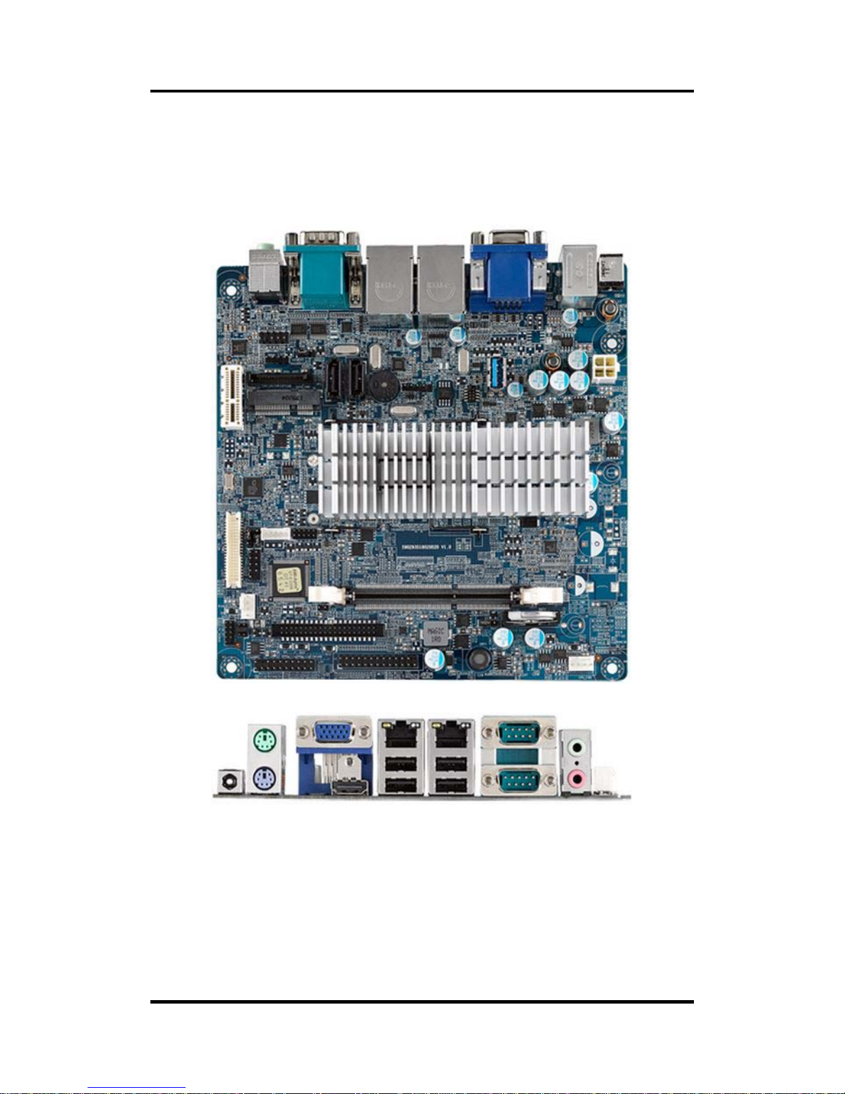
2.1 Board Layout
2.2 Rear Panel I/O
Page 12

MANO840 Mini ITX Motherboard
6 Board and Pin Assignments
2.3 Jumper Settings
Jumper is a small component consisting of jumper clip and jumper pins. Install jumper clip on 2
jumper pins to close. And remove jumper clip from 2 jumper pins to open. The following
illustration shows how to set up jumper.
Before applying power to MANO840 Series, please make sure all of the jumpers are in factory
default position. Below you can find a summary table and onboard default settings.
Note
Once the default jumper setting needs to be changed, please do it under power-off
condition.
Jumper
Description
Setting
CLR_CMOS
Clear CMOS
Default: Normal Operation
1-2 Close
VCON
VCON Voltage Select
Default: Ground
2-3 Close
LCD_PWR1
LVDS Backlight Power Select
Default: +5V
1-2 Close
COM_RI
COM RI/+5V/+12V Select
Default: RI
3-4 Close
SATA_P7
SATA DOM Power Select
Default: GND
1-2 Close
Page 13

MANO840 Mini ITX Motherboard
Board and Pin Assignments 7
2.3.1 Clear CMOS (CLR_CMOS)
This jumper allows you to clear the Real Time Clock (RTC) RAM in CMOS. You can
clear the CMOS memor y of date, time, and system setup parameters by erasing the
CMOS RTC RAM data. The onboard button cell battery powers the RAM data in CMOS,
which includes system setup information such as system passwords.
To erase the RTC RAM:
1. Turn OFF the computer and unplug the power cord.
2. Remove the onboard battery.
3. Move the jumper clip f rom pins 1-2 (default) to pins 2-3. Keep the clip on pins 2-3
for about 5~10 seconds, then move the clip back to pins 1-2.
4. Re-install the battery.
5. Plug the power cord and turn ON the computer.
6. Hold down the <Del> key during the boot process and enter BIOS setup to re-enter
data.
Caution
Except when clearing the RTC RAM, never remove the clip on this jumper
default position. Removing the clip will cause system boot failure!
Note
You do not need to clear the RTC when the system hangs due to
overclocking. For system failure due to overclocking, use the C.P.R. (CPU
Parameter Recall) feature. Shut down and reboot the system so the BIOS
can automatically reset parameter settings to default values.
2.3.2 VCON Voltage Select (VCON)
This jumper allows you to select the panel type of LVDS panel.
2.3.3 LVDS Backlight Power Select (LCD_PWR1)
This jumper allows you to select the panel power mode of LVDS panel.
Function Setting
Normal operation (Default) 1-2 close
Clear CMOS 2-3 close
Function Setting
+3.3 1-2 close
GND(Default) 2-3 close
Function Setting
+5V (Default) 1-2 close
+3.3V 2-3 close
Page 14

MANO840 Mini ITX Motherboard
8 Board and Pin Assignments
2.3.4 COM RI/+5V/+12V Select (COM_RI)
This jumper allows you to select the power mode of COM port.
2.3.5 SATA DOM Power Select (SATA_P7)
This jumper allows you to select the power mode of SATA DOM.
Function Setting
+12V 1-2 close
RI (Default) 3-4 close
+5V 5-6 close
Function Setting
GND (Default) 1-2 close
+5V 2-3 close
Page 15

MANO840 Mini ITX Motherboard
Board and Pin Assignments 9
2.4 Connectors
Signals go to other parts of the system through connectors. Loose or impr oper connection
might cause problems, please mak e sure all connectors are properly and f irmly connected.
Here is a summary table which shows connectors on the hardware.
Connector Description
DC_IN 12V DC Inlet
PSKBM PS/2 Keyboard and Mouse Mini Din
HDMI HDMI Port
VGA VGA Port
USBLAN1 LAN1 and 2 USB 2.0 Port
USBLAN2 LAN2 and 2 USB 2.0 Port
COM COM1 and COM2 Ports
AUDIO Audio Jack
CPU_FAN CPU Fan Connector
SYS_FAN System Fan Connector
DIO Digital I/O Connector
F_PANEL Front Panel Connector
ATX12V ATX Power Connector
F_AUDIO Audio Connector
LVDS LVDS Connector
LVDSPW LCD Inverter Connector
SATA_PWR SATA Power Connector
SPKR Speaker Connector
SATA1~SATA2 SATA Connectors
F_USB USB 2.0 Connector
USB3.0 USB 3.0 Connector
JCOM3-1 COM3~COM6 Connector
LPT Parallel Port Connector
PCIE PCI-Express x1 Slot
MPE PCI-Express Mini Card Connector
DIMM 204-pin DDR3L SO-DIMM Socket
Page 16

MANO840 Mini ITX Motherboard
10 Board and Pin Assignments
2.4.1 Rear Panel Connectors
1. DC_IN. This inlet is for 12V DC inlet.
2. PS/2 mouse port (green). This port is for a PS/2 mouse.
3. PS/2 keyboard port (purple). This port is for a PS/2 keyboard.
4. VGA port. This 15-pin VGA port connects to a VGA monitor.
5. HDMI port. This 19-pin HDMI 1.3 port connects to a HDMI monitor.
6. LAN (RJ-45) ports. Each o f these ports allows Gig ab it c onn ec tio n t o a L oc al Are a
Network (LAN) throu gh a network hub. Ref er to the table below for the LAN port
LED indications.
7. USB 2.0 ports 1~4. These four 4-pin Universal Serial Bus (USB) ports are
available for connecting USB 2.0 devices.
8. Serial connector. This 9-pin COM1 port is for serial devices.
9. Serial connector. This 9-pin COM2 port is for serial devices.
10. Line-out port (Green). This port connects a headphone or a speaker.
11. Microphone port (pink). This port connects a microphone.
2.4.2 FAN Connectors (CPU_FAN and SYS_FAN)
The fan connectors suppor t cooling f ans of 280m A (3.36 W max.) at 4800rpm or a total
of 1A~2.22A (26.64W max.) at +12V. Connect the fan cables to the fan connectors on
the motherboard, making sure that the b lack wire of each c ab le matches the ground pi n
of the connector.
CPU fan interface is avai la ble through CPU_FAN, see table below.
ACT/LINK LED SPEED LED
Status
Description
Status
Description
OFF No link OFF 10Mbps connection
Yellow Link Orange 100Mbps connection
Blinking Data activity Green 1Gbps connection
Pin Signal
1 GND
2 +12V
3 SENSE
4 GPO
Page 17

MANO840 Mini ITX Motherboard
Board and Pin Assignments 11
System fan interface is available through SYS_FAN, see table below.
Caution
Do not forget to connect the fan cables to the fan connectors. Insufficient
air flow inside the system may damage the motherboard components.
These are not jumpers! DO NOT place jumper caps on the fan conne ctors.
2.4.3 Digital I/O Connector (DIO)
This connector is for GPIO function.
2.4.4 Front Panel Connector (F_PANEL)
This connector is for a c has sis-m ounted f ront panel I/O module that supp orts power on/
reset switch and HDD/ power LED indicator. The functions are described as follows.
2
1
ATX Power Button/Soft-off Button (Pin 6-8 PWRBT)
This 2-pin connector is for the system power button. Pressing the power button turns the
system on or puts the system in sleep or soft -off mode depending on th e BIOS s et tings.
Pressing the power switch and h old in g it f or m ore than four seconds while the sys tem is
ON turns the system OFF.
Reset Button (Pin 5-7 SYS_RST)
This 2-pin connector is for the chassis-m ounted reset button for s ystem reboot without
turning off the system power.
Power LED (Pin 2-4 PWRLED)
This 2-pin connector is for the system power LED. Connect the chassis power LED
cable to this connector. The system power LED lights up w hen you turn on th e system
power, and blinks when the system is in sleep mode.
Pin
Signal
1 GND
2 +12V
3 SENSE
4 GPO
Pin Signal Pin Signal
1 GPIO_S0_SC17_DI 2 GPIO_S0_SC21_DO
3 GPIO_S0_SC18_DI 4 GPIO_S0_SC22_DO
5 GPIO_S0_SC19_DI 6 GPIO_S0_SC23_DO
7 GPIO_S0_SC20_DI 8 GPIO_S0_SC24_DO
9 5VSB 10 GND
Pin Signal Pin Signal
1 HDDLED+ 2 POWERLED+3 HDDLED- 4 POWERLED5 GND 6 PWSWITCH
7 RESET 8 GND
9 NC
1
2
Page 18

MANO840 Mini ITX Motherboard
12 Board and Pin Assignments
Hard Disk Drive Activity LED (Pin 1-3 HDLED)
This 2-pin connector is for the HDD Activity LED. Connect the HDD Activity LED cable to
this connector. The IDE LED lights up or flashes when data is read from or written to the
HDD.
2.4.5 ATX Power Connector (ATX12V)
The connector is for A TX power supply plugs. The power supply plugs are designed to fit
these connectors in only one orientation. Find the proper orientation and push down
firmly until the connectors completely fit.
Note
Use of a PSU with a higher power output is recommended when
configuring a system with more power-consuming devices. The
system may become unstable or may not boot up if the power is
inadequate.
Make sure that your power supply unit (PSU) can provide at least the
minimum power required by your system.
2.4.6 Audio Connector (F_AUDIO)
This connector is for a chassis-mounted front panel audio I/O module that supports
either HD Audio or legacy AC ‘97 (optional) audio standard. Connect one end of the front
panel audio I/O module cable to this connector.
1
Important
For motherboards with the optional HD Audio feature, we recommend that
you connect a high-definition fron t panel audi o modu l e to thi s conne ctor t o
avail of the motherboard’s high-definition audio capability.
Pin Signal Pin Signal
1 GND 3 +12V
2 GND 4 +12V
Pin Signal Pin Signal
1 MIC2_L 2 AUGND
3 MIC2_R 4 FP_AUD_DETECT
5 HPOUT-R 6 MIC2-JD
7 AUGND 8 NC
9 HPOUT-L 10 HPOUT-JD
1
2
Page 19

MANO840 Mini ITX Motherboard
Board and Pin Assignments 13
2.4.7 LVDS Connector (LVDS)
The connector is for 24-bit dual channel LVDS panel.
Pin Signal Pin Signal
1 LCD_VDD 2 LCD_VDD
3 GND 4 GND
5 LCD_VDD 6 LCD_VDD
7 TXO0- 8 TXE09 TXO0+ 10 TXE0+
11 GND 12 GND
13 TXO1- 14 TXE115 TXO1+ 16 TXE1+
17 GND 18 GND
19 TXO2- 20 TXE221 TXO2+ 22 TXE2+
23 GND 24 GND
25 TXOC- 26 TXEC27 TXOC+ 28 TXEC+
29 GND 30 GND
31 DDC_CLK 32 DDC_DATA
33 GND 34 GND
35 TXO3- 36 TXE337 TXO3+ 38 TXE3+
39 BKLT_EN 40 VCON
Page 20

MANO840 Mini ITX Motherboard
14 Board and Pin Assignments
2.4.8 LCD Inverter Connector (LVDSPW)
The connector is for the control of internal LVDS brightness.
1
Signal Description:
PWM
For inverter with adjustable backlight function, it is possible to control the LCD
brightness through the PWM signal.
ENBKL
LCD backlight ON/OFF control signal.
2.4.9 SATA Power Connector (SATA_PWR)
This connector supports SATA device power.
Pin Signal
1 +12V
2 GND
3 ENBKL
4 PWM
5 +5V
Pin Signal
1 3.3V
2 3.3V
3 3.3V
4 GND
5 GND
6 GND
7 5V
8 5V
9 5V
10 GND
11 GND
12 GND
13 12V
14
12V
15 12V
Vadj = 0.75V ~ 4.25V
(Recommended: 4.7KΩ, >1/16W)
1
Page 21

MANO840 Mini ITX Motherboard
Board and Pin Assignments 15
2.4.10 Speaker Connector (SPKR)
This connector supports speaker signal.
2.4.11 SATA Connectors (SATA1 and SATA2)
These connectors suppor t SATA 2.0 and are for the Serial ATA signal cables for Serial
ATA hard disk drives.
Note
Connect the right-angle side of SATA signal cable to
SATA device. Or you may connect the right-angle
side of SATA cable to the onboard SATA port to
avoid mechanical conflict with large graphics cards.
Pin
Signal
1 SPK-LL2 SPK-LL+
3 SPK-RR4 SPK-RR+
Pin
Signal
1 GND
2 SATA_TXP2
3 SATA_TXN2
4 GND
5 SATA_RXN2
6 SATA_RXP2
7 GND
1
SATA1
SATA2
Page 22

MANO840 Mini ITX Motherboard
16 Board and Pin Assignments
2.4.12 USB 2.0 Connector (F_USB)
This connector is for USB 2.0 port. Connect the optional USB module cable to this
connector then install the module to a slot openi ng at the back of the s ystem chassis.
This USB connector complies with USB 2.0 s pecification that supports up to 48 0Mbps
connection speed.
2.4.13 USB 3.0 Connector (USB3.0)
This connector prov ides USB Rev. 3.0 supporting transm ission rate up to 5Gbps and
fuse protect.
Pin
Signal
1 PS2_USB
2 USB_DN2_CMK
3 USB_DP2_CMK
4 GND
5 NC
Pin
Signal
1 VCC
2 -DATA1
3 +DATA1
4 GND
5 -SRX1
6 +SRX1
7 GND
8 -STX1
9 +STX1
1
Page 23

MANO840 Mini ITX Motherboard
Board and Pin Assignments 17
2.4.14 COM Connector (JCOM3-1)
This connector is for four serial ports (COM3~COM6). Connect the serial port m odule
cable to this connector then install the module to a slot opening at the back of the system
chassis.
2.4.15 Parallel Port Connector (LPT)
This connector is for parallel port function.
Pin Signal Pin Signal
1 COM3_DCD# 2 COM3_DSR#
3 COM3_RXD 4 COM3_RTS#
5 COM3_TXD 6 COM3_CTS#
7 COM3_DTR# 8 RI3xPOWER
9 GND 10 GND
11 COM4_DCD# 12 COM4_DSR#
13 COM4_RXD 14 COM4_RTS#
15 COM4_TXD 16 COM4_CTS#
17 COM4_DTR# 18 COM4_RI#
19 GND 20 GND
21 COM5_DCD# 22 COM5_DSR#
23 COM5_RXD 24 COM5_RTS#
25 COM5_TXD 26 COM5_CTS#
27 COM5_DTR# 28 COM5_RI#
29 GND 30 GND
31 JDDCD6# 32 COM6_DSR#
33 JRRXD6 34 COM6_RTS#
35 JTTXD6 36 COM6_CTS#
37 JDDTR6# 38 COM6_RI#
39 GND 40 GND
Pin Signal Pin Signal
1 -NSTB 14 -AFD
2 PD0 15 -ERROR
3 PD1 16 -INIT
4 PD2 17 -SLIN
5 PD3 18 GND
6 PD4 19 GND
7 PD5 20 GND
8 PD6 21 GND
9 PD7 22 GND
10 ACK_L 23 GND
11 BUSY 24 GND
12 PE 25 GND
13
SLCT
26
NC
1
1
14
Page 24

MANO840 Mini ITX Motherboard
18 Board and Pin Assignments
This page is intentionally left blank.
Page 25

MANO840 Mini ITX Motherboard
Hardware Installation 19
Chapter 3
Hardware Installation
Tak e note of the fol lowing prec autions befor e you install m otherboard com ponents or chan ge
any motherboard settings.
Caution
Unplug the power cord from the wall socket before touching any component.
Use a grounded wrist strap or touch a safely grounded object or a metal
object, such as the power supply case, before handling components to avoid
damaging them due to static electricity.
Hold components by the edges to avoid touching the ICs on them.
Whenever you uninstall any component, pl ace it o n a gro unded ant i-static pa d
or in the bag that came with the component.
Before you install or remove any component, ensure that the ATX power
supply is switched off or the power cord is detached from the power supply.
Failure to do so may cause severe damage to the motherboard, peripherals,
and/or components.
3.1 Motherboard Overview
Before you install the mother board, stud y the configuratio n of your chass is to ensure that t he
motherboard fits into it. Refer to the chassis documentation before installing the motherboard.
Warning
Make sure to unplug the power cord before installing or removing the
motherboard. Failure to do so can cause you physical injury and damage
motherboard components.
3.1.1 Placement Direction
When installing the m otherboard, make sure that you pl ace it into the chassis in the
correct orientation. The ed ge with exter nal ports goes to th e rear part of the ch assis as
indicated in the image below.
3.1.2 Screw Holes
Place four (4) screws into the holes indicated by circles to secure the motherboard to the
chassis.
Caution
Do not over-tighten the screws! Doing so can damage the motherboard.
Page 26

MANO840 Mini ITX Motherboard
20 Hardware Installation
Place this side towards the rear of the chassis.
3.2 System Memory
3.2.1 Overview
The motherboard com es with one 204-pin Dou ble Data Rate 3 Low voltage (DDR3L)
Small Outline Dual Inline Memory Modules (SO-DIMM) socket.
A DDR3L module has the same ph ysical dimensions as a DDR SO-DIMM but has a
204-pin footprint compared to the 204-pin DDR2 DIMM. DDR3L DIMMs are notched
differently to prevent installation on a DDR2 DIMM socket. The following figure illustrates
the location of the sockets:
204-pin DDR3L SO-DI MM socket
Channel Socket
Channel A DIMM
Page 27

MANO840 Mini ITX Motherboard
Hardware Installation 21
3.2.2 Memory Configurations
You may install 1GB, 2GB, 4GB and 8GB non-ECC DDR3L SO-DIMM into the SO-DIMM
socket using the memory configurations in this section.
Important
If you installed over 4GB memory module, the system may detect
less than 3GB of total memory because of address space allocation
for other critical functions. This limitation applies to Windows 32-bit
version operating system since it does not support PAE (Physical
Address Extension) mode.
If you install Windows 32-bit version operating system, we
recommend that you install less than 3GB of total memory.
Due to CPU limitation, SO-DIMM modules with 128Mb memory chips
or double-sided x16 memory chips are not supported in this
motherboard.
3.3.3 Installing a SO-DIMM
1. Unlock a SO-DIMM socket by pressing the retaining clips outward.
Page 28

MANO840 Mini ITX Motherboard
22 Hardware Installation
2. Align a SO-DIMM on the socket suc h th at t he notch on the SO-DIMM matc hes the
break on the socket.
3. Firmly insert the SO-DIMM into the sock et until the retaining clips snap back in
place and the SO-DIMM is properly seated.
Important
A DDR3L SO-DIMM is keyed with a notch so that it fits in only one
direction. DO NOT force a SO-DIMM into a socket to avoid damaging
the SO-DIMM.
The DDR3L SO-DIMM socket does not support DDR2 SO-DIMM. DO
NOT install DDR2 SO-DIMM to the DDR3L SO-DIMM socket.
Caution
Make sure to unplug the power supply before adding or removing
SO-DIMM or other system components. Failure to do so may cause
severe damage to both the motherboard and the components.
DDR3L SO-DIMM notch
Unlocked retaini n g clip
Locked retaining clip
Page 29

MANO840 Mini ITX Motherboard
Hardware Installation 23
3.2.4 Removing a SO-DIMM
1. Simultaneously press the retaining clips downward to unlock the SO-DIMM.
2. Remove the SO-DIMM from the socket.
Note
Support the SO-DIMM lightly with your fingers when pressing the
retaining clips. The SO-DIMM might get damaged when it flips out with
extra force.
3.3 Expansion Card
In the future, you may need to install expansion cards. The following sub-sections describe the
slots and the expansion cards that they support.
Warning
Make sure to unplug the power cord before adding or removing expansion cards.
Failure to do so may cause you physical injury and damage motherboard
components.
3.3.1 Installing an Expansion Card
1. Before installing the expansion car d, read the documentation that c ame with it and
make the necessary hardware settings for the card.
2. Remove the system unit cover (if your motherboard is already installed in a
chassis).
3. Remove the bracket oppos ite the slot that you intend to use. Keep th e screw for
later use.
4. Align the card connector with the sl ot and press firml y until the card is complete ly
seated on the slot.
5. Secure the card to the chassis with the screw you removed earlier.
6. Replace the system cover.
Unlocked retaini n g clip
Page 30

MANO840 Mini ITX Motherboard
24 Hardware Installation
3.3.2 Configuring an Expansion Card
After installing the expansion card, configure it by adjusting the software settings.
1. Turn on the system and change the necessary BIOS settings, if any. See Chapter 5
for information on BIOS setup.
2. Assign an IRQ to the card if needed.
3. Install the software drivers for the expansion card.
3.3.3 PCI-Express x1 Slot (PCIE)
This motherboard supports one PCI-Express x1. The following figure shows a
PCI-Express x1 card installed on the PCI-Express x1 slot.
3.3.4 PCI-Express Mini Card Connector
This motherboard s upports one PCI-Express Mini Card. The following f igure shows a
PCI-Express Mini Card installed on this connector.
Page 31

MANO840 Mini ITX Motherboard
Hardware Description 25
Chapter 4
Hardware Description
4.1 Microprocessors
The MANO840 Series supports Intel
®
CeleronTM J1900 SoC processor, which enable your
system to operate under Windows
®
7, Windows® 8 and Linux environments. The system
performance depends on the microprocessor. Make sure all corr ect settings are arranged for
your installed microprocessor to prevent the CPU from damages.
4.2 BIOS
The MANO840 Series uses AMI Plug and Play BIOS with a single 64Mb SPI Flash.
4.3 System Memory
The MANO840 Series supports one 204-pin DDR3L SO-DIMM sock et for maximum memory
capacity up to 8GB DDR3L SDRAMs. The mem or y module c omes in sizes of 1GB, 2GB, 4GB
and 8GB.
Page 32
MANO840 Mini ITX Motherboard
26 Hardware Description
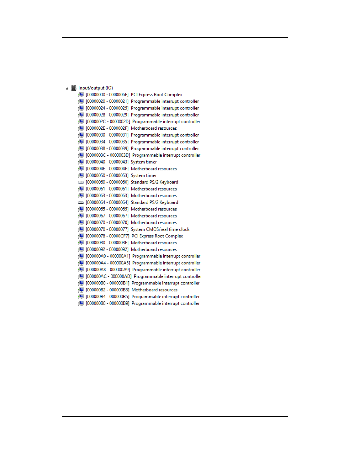
4.4 I/O Port Address Map
The Intel
®
CeleronTM J1900 SoC processor communicates via I/O ports. Total 1KB port
addresses are available for assigning to other devices via I/O expansion cards.
Page 33

MANO840 Mini ITX Motherboard
Hardware Description 27
Page 34

MANO840 Mini ITX Motherboard
28 Hardware Description
4.5 Int e rrupt Controller (IRQ) Map
The interrupt controller (IRQ) mapping list is shown as follows:
Page 35

MANO840 Mini ITX Motherboard
Hardware Description 29
Page 36

MANO840 Mini ITX Motherboard
30 Hardware Description
Page 37

MANO840 Mini ITX Motherboard
Hardware Description 31
Page 38

MANO840 Mini ITX Motherboard
32 Hardware Description
Page 39

MANO840 Mini ITX Motherboard
Hardware Description 33
Page 40

MANO840 Mini ITX Motherboard
34 Hardware Description
Page 41

MANO840 Mini ITX Motherboard
Hardware Description 35
4.6 Memory Map
The memory mapping list is shown as follows:
Page 42

MANO840 Mini ITX Motherboard
36 Hardware Description
This page is intentionally left blank.
Page 43

MANO840 Mini ITX Motherboard
AMI BIOS Setup Utility 37
Chapter 5
AMI BIOS Setup Utility
The AMI UEFI BIOS provides users with a built-in setup program to modify basic system
configuration. All configured parameters are stored in a flash chip to save the setup information
whenever the power is turn ed off. This chapter provide s users with detailed desc ription about
how to set up basic system configuration through the AMI BIOS setup utility.
5.1 Starting
To enter the setup screens, follow the steps below:
1. Turn on the computer and press the <Del> key immediately.
2. After you press the <Del> key, the main BIOS setup m enu displa ys. You can access the
other setup screens from the main BIOS setup menu, such as the Advanced and Chipset
menus.
Note
If your computer cannot boot after making and saving system changes with BIOS
setup, you can restore BIOS optimal defaults by setting CLR_CMOS (see section
2.3.1).
It is strongly recomm ended that you should avoid ch anging the chipset’s defaults. Both AMI
and your system manufacturer have carefully set up these defaults that provide the best
performance and reliability.
5.2 Navigat ion Keys
The BIOS setup/utilit y uses a key-based n avigati on system called hot k eys. Most of the BIOS
setup utility hot keys can be used at any time during the setup navigation process. These keys
include <F1>, <F 2>, <Enter>, <ESC>, <Arrow> keys, and so on.
Note
Some of the navigation keys differ from one screen to another.
Page 44

MANO840 Mini ITX Motherboard
38 AMI BIOS Setup Utility
Hot Keys Description
Left/Right
The Left and Right <Arrow> keys allow you to select a setup screen.
Up/Down
The Up and Down <Arrow> keys allow you to select a setup screen or
sub-screen.
Enter
The <Enter> key allows you to display or change the setup option listed for a
particular setup item. The <Enter> key can also allow you to display the
setup sub- screens.
+− Plus/Minus
The Plus and Minus <Arrow> keys allow you to change the field value of a
particular setup item.
F1
The <F1> key allows you to display the General Help screen.
F2
The <F2> key allows you to Load Previous Values.
F3
The <F3> key allows you to Load Optimized Defaults.
F4
The <F4> key allows you to save any changes you have made and exit
Setup. Press the <F4> key to save your changes.
Esc
The <Esc> key allows you to discard any changes you have made and exit
the Setup. Press the <Esc> key to exit the set
up without saving your
changes.
Page 45

MANO840 Mini ITX Motherboard
AMI BIOS Setup Utility 39
5.3 Main Menu
When you first enter the setup utility, you will enter the Main setup s creen. You can always
return to the Main setup screen by selecting the Main tab. System Time/Date can be set up as
described below. The Main BIOS setup screen is shown below.
BIOS Information
Display the auto-detected BIOS infor mation.
System Date/Time
Use this option to ch ange the system time and date. High light System Time or System Date
using the <Arrow> ke ys. Enter new values through t he ke yboard. Press the <Tab> key or the
<Arrow> keys to m ove between fields. T he date must be entered in MM/DD/YY form at. The
time is entered in HH:MM:SS format.
Page 46

MANO840 Mini ITX Motherboard
40 AMI BIOS Setup Utility
5.4 Advanced Menu
Launch PXE OpROM
Enable or disable the boot ROM funct ion of the onboard LAN chip when the system boots
up.
The Advanced menu also allows users to set configuration of the CPU and other system
devices. You can select any of the items in the left frame of the screen to go to the sub menus:
► ACPI Settings
► RTC Wake Settings
► CPU Configuration
► SATA Configuration
► Intel IGD SWSCI OpRegion
► USB Configuration
► Super IO Configuration
► H/W Monitor
► TXE Configuration
► Trusted Computing
► DIO Configuration
For items marked with “”, please press <Enter> for more options.
Caution
Take caution when changing the settings of the Advanced menu items. Incorrect
field values can cause the system to malfunction.
Page 47

MANO840 Mini ITX Motherboard
AMI BIOS Setup Utility 41
ACPI Settings
You can use this screen to select options for the ACPI configuration, and change the value
of the selected option. A description of the selected item appears on the ri ght side of the
screen.
ACPI Sleep State
Select the highest ACPI sleep state the system will enter when the suspend button is
pressed. Configuration options are Suspend Disabled and S3 (Suspend to RAM).
Page 48

MANO840 Mini ITX Motherboard
42 AMI BIOS Setup Utility
RTC Wake Settings
Wake system with Fixed Time
Enable or disable system wake on alarm even. When enabled, system will wak e upon th e
hr/min/sec specified.
Page 49

MANO840 Mini ITX Motherboard
AMI BIOS Setup Utility 43
CPU Configuration
This screen shows the CPU information.
Page 50

MANO840 Mini ITX Motherboard
44 AMI BIOS Setup Utility
SATA Configuration
In this Configuration menu, you can see the currently installed hardware in the SATA ports.
During system boot up, the BIOS automatically detects the presence of SATA devices.
SATA Mode
Determine how SATA controller(s) operate. Operation mode options are Disabled, IDE
Mode and AHCI Mode.
Page 51

MANO840 Mini ITX Motherboard
AMI BIOS Setup Utility 45
Intel IGD SWSCI OpRegion
LCD Panel Type
This option allows you to selec t the type of LCD panel connected to the m otherboard’s
built-in graphics chip.
Page 52

MANO840 Mini ITX Motherboard
46 AMI BIOS Setup Utility
USB Configuration
You can use this screen to select options for the USB Configuration, and change the value
of the selected option. A des cription of the select ed item appears on the right side of the
screen.
USB Devices
Display all detected USB devices.
Legacy USB Support
Enable or disable support f or USB device on legac y operating s ystem . T he default setti ng
is Enabled. Auto option disables legacy support if no USB devices are connected. Disable
option will keep USB devices available only for EFI applications.
XHCI Mode
Enable option allow XHCI mode support. Disable option will keep XHCI mode disable.
Auto option will auto detec t which mode is better. Smart auto option will auto de tect the
suitable mode for device plugged.
Page 53

MANO840 Mini ITX Motherboard
AMI BIOS Setup Utility 47
Super IO Configuration
You can use this screen to select optio ns for the Super IO Configuration, and change the
value of the selected option. A description of the selected item appears on the right side of
the screen. For items marked with “”, please press <Enter> for more options.
Serial Port 1~6 Configuration
Set parameters of serial port 1 (COM1) ~ serial port 6 (COM6).
Change settings
Select an optimal setting for super IO device.
Parallel Port Configuration
Set parameters of LPT port.
Change settings
Select an optimal setting for super IO device.
Restore AC Power Loss
Set the state after power loss.
Watch Dog Timer
Select watchdog count mode second/minute.
Watch Dog Timer Time Out Value
Timer will start to count from end of POST. 00 - Time out Disable.
Page 54

MANO840 Mini ITX Motherboard
48 AMI BIOS Setup Utility
H/W Monitor
Use this screen for Smart Fan configuration and hardware health status monitoring.
This screen displa ys the te mper ature of s ystem and CPU, cooling fan speed in RPM and
system voltages (CPU VCORE, 5V, 5VSB, 12V and 3.3V).
Smart Fan Function
Select CPU fan mode. When this feature is set to automatic the CPU’s fan speed will
rotate according to the CPU’s temperature; the higher the temperature, the faster the
speed of rotation.
Smart Fan Mode Configuration
Select Manual mode or Thermal Cruise mode.
Page 55

MANO840 Mini ITX Motherboard
AMI BIOS Setup Utility 49
TXE Configuration
TXE
Enable or disable TXE firmware.
Page 56

MANO840 Mini ITX Motherboard
50 AMI BIOS Setup Utility
Trusted Computing
Security Device Support
Enable or disable BIOS support for security device.
Page 57

MANO840 Mini ITX Motherboard
AMI BIOS Setup Utility 51
DIO Configuration
Allow user to check digital input 1~4 port state and set digital output 5~8 port setting.
EUP Function
Page 58

MANO840 Mini ITX Motherboard
52 AMI BIOS Setup Utility
5.5 Chipset Menu
The Chipset menu allows u sers to change the ad vanced chipset settin gs. You ca n select any
of the items in the left frame of the screen to go to the sub menus:
► North Bridge
► South Bridge
For items marked with “”, please press <Enter> for more options.
Page 59

MANO840 Mini ITX Motherboard
AMI BIOS Setup Utility 53
North Bridge
This screen is for North Bridge configuration.
DVMT Total Gfx Mem
When set to Max Mode, the graphics driver will reserve a Max. of system memory as
graphics memory, according to system and graphics requirement
DVMT Pre-Allocated
Select DVMT pre-allocated graphics memory size used by the int ernal graphics device
(IGD).
Initiate Graphic Adapter
Set initial graphic adapter.
Page 60

MANO840 Mini ITX Motherboard
54 AMI BIOS Setup Utility
South Bridge
LAN 1/2 Controller
Enable or disable onboard LAN1/LAN2 controller.
Azalia HD Audio
Enable or disable onboard HD Audio controller.
Azalia Internal HDMI Codec
Enable or disable onboard Audio internal HDMI controller.
Resume from LAN1/2
Enable or disable resume from LAN1/LAN2 function.
Resume from WAK# / RING
Enable or disable COM port WAK#/RING function.
Page 61

MANO840 Mini ITX Motherboard
AMI BIOS Setup Utility 55
5.6 Boot Menu
The Boot menu allows users to change boot options of the system.
Operation System Select
Select which OS would be installed. Configuration options are Windows 7 or other OS,
Windows 8.x, W indows 8.x with CSM and Manual.
Quiet Boot
Enable or disable Quiet Boot mode.
Fast Boot
Enable or disable Fast Boot mode.
Setup Prompt Timeout
Increasing the value will make the POST take longer; the default setting is 1 second.
Bootup NumLock State
Select the keyboard number lock status.
Page 62

MANO840 Mini ITX Motherboard
56 AMI BIOS Setup Utility
Boot Mode Select
This item could be set to Legacy or UEFI.
Set Boot Priority
Set boot device priority by BIOS setting.
Page 63

MANO840 Mini ITX Motherboard
AMI BIOS Setup Utility 57
5.7 Security Menu
The Security menu allows users to change the security settings for the system.
Administrator Password
Set setup administrator password.
User Password
Set user password.
Page 64

MANO840 Mini ITX Motherboard
58 AMI BIOS Setup Utility
5.8 Save & Exit Menu
The Save & Exit m enu allows users t o load your s yste m configurati on with optim al or f ail -safe
default values.
Save Changes and Exit
Exit system setup after saving the changes.
Discard Changes and Exit
Exit system setup without saving the changes.
Restore Defaults
Restore/load default values for all the setup option.
 Loading...