

Page 1

MANO831 Series
Intel® AtomTM D2550 Mini ITX
Motherboard
User’s Manual
Page 2

Disclaimers
This manual has been carefully checked and believed to contain accurate information.
Axiomtek Co., Ltd. assumes no responsibility for any infringements of patents or any third
party’s rights, and any liability arising from such use.
Axiomtek does not warrant or assume any legal liability or responsibility for the accuracy,
completeness or usefulness of any information in this document. Axiomtek does not make any
commitment to update the information in this manual.
Axiomtek reserves the right to change or revise this document and/or product at any time
without notice.
No part of this document may be reproduced, stored in a retrieval system, or transmitted, in
any form or by any means, electronic, mechanical, photocopying, recording, or otherwise,
without the prior written permission of Axiomtek Co., Ltd.
CAUTION
If you replace wrong batteries, it causes the danger of explosion. It is recommended by the
manufacturer that you follow the manufacturer’s instructions to only replace the same or
equivalent type of battery, and dispose of used ones.
Copyright 2012 Axiomtek Co., Ltd.
All Rights Reserved
November 2012, Version A1
Printed in Taiwan
ii
Page 3

ESD Precautions
Computer boards have integrated circuits sensitive to static electricity. To prevent chipsets
from electrostatic discharge damage, please take care of the following jobs with precautions:
Do not remove boards or integrated circuits from their anti-static packaging until you are
ready to install them.
Before holding the board or integrated circuit, touch an unpainted portion of the system
unit chassis for a few seconds. It discharges static electricity from your body.
Wear a wrist-grounding strap, available from most electronic component stores, when
handling boards and components.
Trademarks Acknowledgments
Axiomtek is a trademark of Axiomtek Co., Ltd.
Windows® is a trademark of Microsoft Corporation.
AMI is a trademark of American Megatrend Inc.
IBM, PC/AT, PS/2, VGA are trademarks of International Business Machines Corporation.
Intel® is a trademark of Intel Corporation.
Winbond is a trademark of Winbond Electronics Corp.
Realtek is a trademark of Realtek Semi-Conductor Co., Ltd.
Other brand names and trademarks are the properties and registered brands of their
respective owners.
iii
Page 4

Warning
Information to prevent injury to yourself when trying to complete a task.
Caution
Information to prevent damage to the components when trying to complete a
task.
Important
Instructions that you MUST follow to complete a task.
Note
Tips and additional information to help you complete a task.
Conventions Used in This Manual
To make sure that you perform certain tasks properly, take note of the following symbols used
throughout this manual.
iv
Page 5

Table of Contents
Disclaimers ..................................................................................................... ii
ESD Precautions ........................................................................................... iii
Conventions Used in This Manual ............................................................... iv
Chapter 1 Introduction ............................................. 1
1.1 Features ............................................................................................... 1
1.2 Specifications ...................................................................................... 2
1.3 Utilities Supported .............................................................................. 3
1.4 Block Diagram ..................................................................................... 4
Chapter 2 Board and Pin Assignments .................... 5
2.1 Board Layout ....................................................................................... 5
2.2 Jumper Settings .................................................................................. 7
2.2.1 Clear CMOS (JCMOS1) .............................................................................. 8
2.2.2 COM3 RS-232/422/485 Mode Setting (JP1, JP2, JP3) .............................. 8
2.2.3 COM4 RS-232/422/485 Mode Setting (JP4, JP5, JP6) .............................. 9
2.2.4 COM3 RI/+5V/+12V Selection (JCOMPWR3) ............................................ 9
2.2.5 COM4 RI/+5V/+12V Selection (JCOMPWR4) ............................................ 9
2.2.6 LVDS Backlight Power Selection (JLVDS_P1) ............................................ 9
2.2.7 AT/ATX Power Mode Selection (JDS6) ..................................................... 10
2.2.8 SATA Port 2 Function Selection (JSATA_SEL1) ....................................... 10
2.2.9 System Deep S5 Power Saving Control (JDS5) ....................................... 10
2.3 Connectors ........................................................................................ 11
2.3.1 Rear Panel Connectors ............................................................................. 12
2.3.2 FAN Connectors (CPU_FAN1 and SYS_FAN1) ....................................... 12
2.3.3 Front Panel Connector (F_PANEL) ........................................................... 13
2.3.4 ATX Power Connector (ATX12V) .............................................................. 14
2.3.5 Serial Connectors (COM3 and COM4) ..................................................... 14
2.3.6 Internal Audio Connector (AAFP1) ............................................................ 15
2.3.7 Digital Audio Connector (SPDIF_OUT1) ................................................... 15
2.3.8 TPM Connector (TPM1) ............................................................................ 16
2.3.9 Serial ATA Connectors (SATA1 and SATA2) ............................................. 16
2.3.10 USB Connectors (USB45 and USB6) ....................................................... 17
2.3.11 Keyboard/Mouse Connector (KB1) ........................................................... 17
2.3.12 LVDS Connectors (JLVDS1 and JLVDS2) ................................................ 18
2.3.13 LVDS Backlight Connector (JBKL1) .......................................................... 19
2.3.14 GPIO Connector (JDIO1) .......................................................................... 19
2.3.15 Serial ATA Power Connectors (SATAPW1 and SATAPW2) ...................... 19
v
Page 6

Chapter 3 Hardware Installation ........................... 21
3.1 Motherboard Overview ..................................................................... 21
3.1.1 Placement Direction .................................................................................. 21
3.1.2 Screw Holes .............................................................................................. 21
3.2 Central Processing Unit (CPU) ......................................................... 22
3.2.1 CPU Location ............................................................................................ 22
3.2.2 The CPU Heatsink and Fan ...................................................................... 23
3.3 System Memory ................................................................................. 24
3.3.1 Overview ................................................................................................... 24
3.3.2 Memory Configurations ............................................................................. 25
3.3.3 Installing a SO-DIMM ................................................................................ 25
3.3.4 Removing a SO-DIMM .............................................................................. 27
3.4 Expansion Card ................................................................................. 27
3.4.1 Installing an Expansion Card..................................................................... 27
3.4.2 Configuring an Expansion Card ................................................................ 28
3.4.3 PCI Slot ..................................................................................................... 28
3.4.4 PCI-Express Mini Card Connector ............................................................ 28
3.4.5 CompactFlashTM Socket ............................................................................ 29
Chapter 4 Hardware Description ........................... 31
4.1 Microprocessors ............................................................................... 31
4.2 BIOS ................................................................................................... 31
4.3 System Memory ................................................................................. 31
4.4 I/O Port Address Map ................................ ................................ ........ 32
4.5 Interrupt Controller (IRQ) Map ......................................................... 34
4.6 Memory Map ...................................................................................... 37
Chapter 5 AMI BIOS Setup Utility .......................... 39
5.1 Starting ............................................................................................... 39
5.2 Navigation Keys ................................................................................ 39
5.3 Main Menu .......................................................................................... 41
5.4 Advanced Menu ................................................................................. 42
5.5 Chipset Menu ..................................................................................... 53
5.6 Boot Menu .......................................................................................... 58
5.7 Security Menu .................................................................................... 60
5.8 Save & Exit Menu .............................................................................. 61
vi
Page 7

MANO831 Mini ITX Board
Chapter 1
Introduction
The MANO831 is designed to unleash the power of the new Intel® Atom™ processor D2550
which supports the new revolutionary two–chip layout. The Intel® Cedarview processor also
provides additional flexibility and upgradeability with two slots of single channel DDR3 memory
at 1066 MHz supporting up to 4GB maximum. With breakthrough low-power silicon, MANO831
can be used with a passive thermal solution based on the recommended boundary conditions.
MANO831 represents a fundamental shift in system design—small, yet powerful enough to
enable a big internet experience for all audiences.
1.1 Features
Intel
2 DDR3 1066/800MHz up to 4GB
7 USB 3.0 supported
2 SATA 2.0 supported
CompactFlash
®
AtomTM D2550
TM
supported
Introduction 1
Page 8

MANO831 Mini ITX Board
1.2 Specifications
CPU
Intel
System Chipset
Intel
BIOS
AMI 16Mb SPI ROM.
System Memory
D2550: Two 204-pin SO-DIMM sockets support up to 4GB single channel DDR3
Onboard Multi I/O
Controller: Winbond 83627DHG.
Serial ports: Two RS-232 ports with 5V/12V power and two RS-232/422/485 with
One PS/2 keyboard/mouse.
Serial ATA
Two SATA 2.0 ports (3Gb/s performance).
USB Interface
Seven USB 2.0 ports.
Display
One DVI
One VGA
Two LVDS.
Ethernet
Two Realtek RTL8111E Gigabit LAN.
Audio
HD audio compliant (with MIC-in/line-out/line-in and front audio header) via Realtek
Expansion Interface
One PCI slot.
One PCI-Express Mini Card.
One CompactFlash
Hardware Monitoring
Monitoring temperature, voltage and cooling fan status. Auto throttling control when
Watchdog Timer
1~255 seconds; up to 256 levels.
Power Management
ACPI (Advanced Configuration and Power Interface).
®
AtomTM D2550 1.86GHz dual-core processor.
®
NM10.
1066/800MHz SDRAM.
5V/12V power.
ALC892.
TM
socket.
CPU overheats.
2 Introduction
Page 9

Note
All specifications and images are subject to change without notice.
Form Factor
Mini ITX form factor.
1.3 Utilities Supported
Chipset driver
Ethernet driver
Graphics driver
Audio driver
TPM driver
ME driver
RAID driver
USB3.0 driver
MANO831 Mini ITX Board
Introduction 3
Page 10

MANO831 Mini ITX Board
1.4 Block Diagram
4 Introduction
Page 11

Board and Pin Assignments
2.1 Board Layout
MANO831 Mini ITX Board
Chapter 2
Top View
Board and Pin Assignments 5
Page 12

MANO831 Mini ITX Board
Bottom View
6 Board and Pin Assignments
Page 13
MANO831 Mini ITX Board
Jumper
Description
Setting
JCMOS1
Clear CMOS
Default: Normal Operation
1-2 close
JP1
COM3 RS-232/422/485 Mode Setting
Default: RS-232 Mode
1-3, 2-4 close
JP2
1-3, 2-4 close
JP3
1-2 close
JP4
COM4 RS-232/422/485 Mode Setting
Default: RS-232 Mode
1-3, 2-4 close
JP5
1-2 close
JP6
1-3, 2-4 close
JCOMPWR3
COM3 RI/+5V/+12V Selection
Default: RI
3-4 close
JCOMPWR4
COM4 RI/+5V/+12V Selection
Default: RI
3-4 close
JLVDS_P1
LVDS Backlight Power Selection
Default: +3.3V
2-3 close
JDS6
AT/ATX Power Mode Selection
Default: ATX Mode
2-3 close
JSATA_SEL1
SATA Port 2 Function Selection
Default: SATA HDD
2-3 close
JDS5
System Deep S5 Power Saving Control
Default: Normal ACPI S5 State
2-3 close
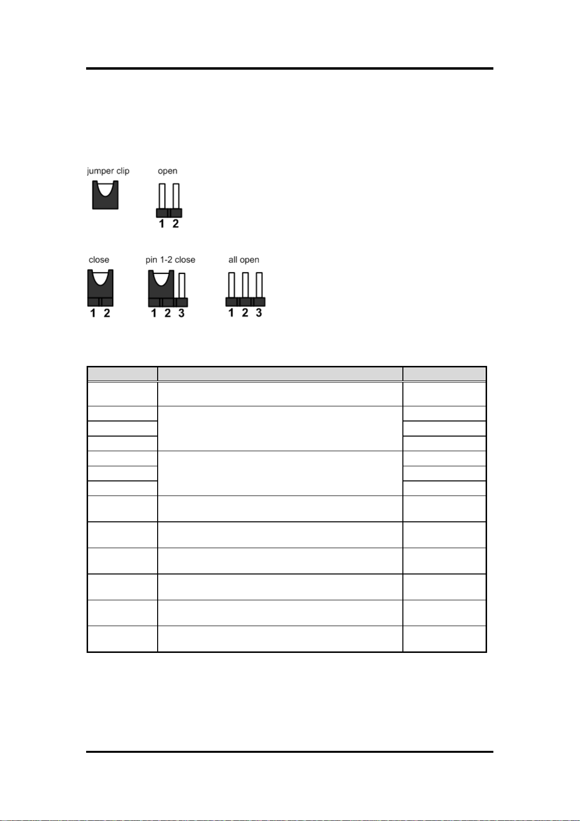
2.2 Jumper Settings
Jumper is a small component consisting of jumper clip and jumper pins. Install jumper clip on 2
jumper pins to close. And remove jumper clip from 2 jumper pins to open. The following
illustration shows how to set up jumper.
Before applying power to MANO831 Series, please make sure all of the jumpers are in factory
default position. Below you can find a summary table and onboard default settings.
Board and Pin Assignments 7
Page 14

MANO831 Mini ITX Board
Caution
Except when clearing the RTC RAM, never remove the cap on this jumper
default position. Removing the cap will cause system boot failure!
Function
Setting
Normal operation (Default)
1-2 close
Clear CMOS
2-3 close
Function
Setting
RS-232 mode
(Default)
JP1 1-3, 2-4 close
JP2 1-3, 2-4 close
JP3 1-2 close
RS-422 mode
JP1 3-5, 4-6 close
JP2 3-5, 4-6 close
JP3 3-4 close
RS-485 mode
JP1 3-5, 4-6 close
JP2 3-5, 4-6 close
JP3 5-6 close
2.2.1 Clear CMOS (JCMOS1)
This jumper allows you to clear the Real Time Clock (RTC) RAM in CMOS. You can
clear the CMOS memory of date, time, and system setup parameters by erasing the
CMOS RTC RAM data. The onboard button cell battery powers the RAM data in CMOS,
which includes system setup information such as system passwords.
To erase the RTC RAM:
1. Turn OFF the computer and unplug the power cord.
2. Remove the onboard battery.
3. Move the jumper cap from pins 1-2 (default) to pins 2-3. Keep the cap on pins 2-3
for about 5~10 seconds, then move the cap back to pins 1-2.
4. Re-install the battery.
5. Plug the power cord and turn ON the computer.
6. Hold down the <Del> key during the boot process and enter BIOS setup to re-enter
data.
2.2.2 COM3 RS-232/422/485 Mode Setting (JP1, JP2, JP3)
This jumper allows you to select the operation mode of COM port 3.
8 Board and Pin Assignments
Page 15

MANO831 Mini ITX Board
Function
Setting
RS-232 mode
(Default)
JP4 1-3, 2-4 close
JP5 1-2 close
JP6 1-3, 2-4 close
RS-422 mode
JP4 3-5, 4-6 close
JP5 3-4 close
JP6 3-5, 4-6 close
RS-485 mode
JP4 3-5, 4-6 close
JP5 5-6 close
JP6 3-5, 4-6 close
Function
Setting
+12V
1-2 close
RI (Default)
3-4 close
+5V
5-6 close
Function
Setting
+12V
1-2 close
RI (Default)
3-4 close
+5V
5-6 close
Function
Setting
+5V
1-2 close
+3.3V (Default)
2-3 close
2.2.3 COM4 RS-232/422/485 Mode Setting (JP4, JP5, JP6)
This jumper allows you to select the operation mode of COM port 4.
2.2.4 COM3 RI/+5V/+12V Selection (JCOMPWR3)
This jumper allows you to select the power mode of COM port 3.
2.2.5 COM4 RI/+5V/+12V Selection (JCOMPWR4)
This jumper allows you to select the power mode of COM port 4.
2.2.6 LVDS Backlight Power Selection (JLVDS_P1)
This jumper allows you to select LVDS backlight power.
Board and Pin Assignments 9
Page 16

MANO831 Mini ITX Board
Function
Setting
AT mode
1-2 close
ATX mode (Default)
2-3 close
Function
Setting
CF
1-2 close
SATA HDD (Default)
2-3 close
Function
Setting
Deep S5 state
1-2 close
Normal ACPI S5 state (Default)
2-3 close
2.2.7 AT/ATX Power Mode Selection (JDS6)
This jumper allows you to select AT mode or ATX mode.
2.2.8 SATA Port 2 Function Selection (JSATA_SEL1)
2.2.9 System Deep S5 Power Saving Control (JDS5)
10 Board and Pin Assignments
Page 17

MANO831 Mini ITX Board
Connector
Description
COM1, COM2
COM1 and COM2 Connector
VGA1
VGA Port
DC1
12V DC IN
DVI
DVI–D Port
LAN1_USB23
LAN1 and USB 2.0 Connector
LAN2_USB01
LAN2 and USB 2.0 Connector
Audio1
Audio Jack
SODIMM_1
204-pin DDR3 SO-DIMM Slot 1
SODIMM_2
204-pin DDR3 SO-DIMM Slot 2
PCI
PCI Slot
MINI-CARD1
PCI-Express Mini Card Connector
CF1
CompactFlashTM Socket
CPU_FAN1
CPU Fan Connector
SYS_FAN1
System Fan Connector
F_PANEL
Front Panel Connector
ATX12V
ATX Power Connector
COM3, COM4
Serial Connectors
AAFP1
Internal Audio Connector
SPDIF_OUT1
Digital Audio Connector
TPM1
TPM Connector
SATA1, SATA2
Serial ATA Connectors
USB45, USB6
USB Connectors
KB1
Keyboard/Mouse Connector
JLVDS1, JLVDS2
LVDS Connectors
JBKL1
LVDS Backlight Connector
JDIO1
GPIO Connector
SATAPW1, SATAPW2
Serial ATA Power Connectors
2.3 Connectors
Signals go to other parts of the system through connectors. Loose or improper connection
might cause problems, please make sure all connectors are properly and firmly connected.
Here is a summary table which shows all connectors on the hardware.
Board and Pin Assignments 11
Page 18

MANO831 Mini ITX Board
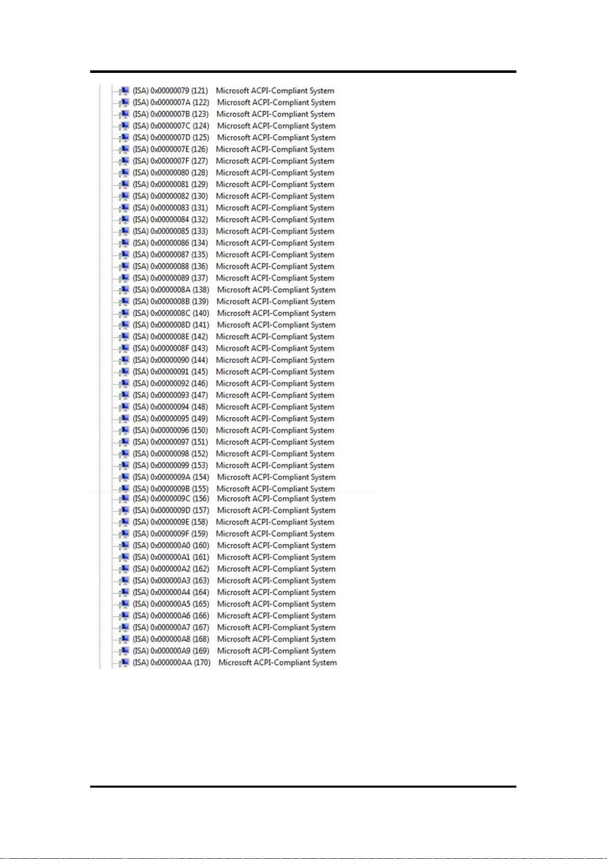
Caution
Do not forget to connect the fan cables to the fan connectors. Insufficient
air flow inside the system may damage the motherboard components.
These are not jumpers! DO NOT place jumper caps on the fan connectors.
Pin
Signal
1
GND
2
+12VPWM
3
Sensor
Pin
Signal
1
GND
2
+12VPWM
3
Sensor
1
1
2.3.1 Rear Panel Connectors
2.3.2 FAN Connectors (CPU_FAN1 and SYS_FAN1)
The fan connectors support cooling fans of 280mA (3.36 W max.) at 4800rpm or a total
of 1A (12W max.) at +12V. Connect the fan cables to the fan connectors on the
motherboard, making sure that the black wire of each cable matches the ground pin of
the connector.
CPU fan interface is available through CPU_FAN1, see table below.
System fan interface is available through SYS_FAN1, see table below.
12 Board and Pin Assignments
Page 19

MANO831 Mini ITX Board
Pin
Signal
1
HDD_LED+
2
SUPLED
3
SATA_LED#
4
GND
5
GND
6
PANSWIN#
7
SRST#
8
GND
9
NC
2.3.3 Front Panel Connector (F_PANEL)
This connector is for a chassis-mounted front panel I/O module that supports power
on/reset switch and HDD/power LED indicate.
1
2
ATX Power Button/Soft-off Button (Pin 6-8 PWRBT)
This 2-pin connector is for the system power button. Pressing the power button turns the
system on or puts the system in sleep or soft-off mode depending on the BIOS settings.
Pressing the power switch and holding it for more than four seconds while the system is
ON turns the system OFF.
Reset Button (Pin 5-7 SYS_RST)
This 2-pin connector is for the chassis-mounted reset button for system reboot without
turning off the system power.
Power LED (Pin 2-4 PWRLED)
This 2-pin connector is for the system power LED. Connect the chassis power LED
cable to this connector. The system power LED lights up when you turn on the system
power, and blinks when the system is in sleep mode.
Hard Disk Drive Activity LED (Pin 1-3 HDLED)
This 2-pin connector is for the HDD Activity LED. Connect the HDD Activity LED cable to
this connector. The IDE LED lights up or flashes when data is read from or written to the
HDD.
Board and Pin Assignments 13
Page 20

MANO831 Mini ITX Board
Note
Use of a PSU with a higher power output is recommended when
configuring a system with more power-consuming devices. The
system may become unstable or may not boot up if the power is
inadequate.
Make sure that your power supply unit (PSU) can provide at least the
minimum power required by your system.
Pin
Signal
Pin
Signal
1
GND
3
+12V
2
GND
4
+12V
Pin
Signal
1
DDCD2#
2
RRXD2
3
TTXD2
4
DDTR2#
5
GND
6
DDSR2#
7
RRTS2#
8
CCTS2#
9
RRI2
1
1
2.3.4 ATX Power Connector (ATX12V)
This connector is for ATX power supply plug. The power supply plug is designed to fit
this connector in only one orientation. Find the proper orientation and push down firmly
until the connector completely fit.
2.3.5 Serial Connectors (COM3 and COM4)
These connectors are for serial (COM) ports. Connect the serial port module cable to
this connector, then install the module to a slot opening at the back of the system
chassis.
COM3, COM4
14 Board and Pin Assignments
Page 21

MANO831 Mini ITX Board
Important
For motherboards with the optional HD Audio feature, we recommend that
you connect a high-definition front panel audio module to this connector to
avail of the motherboard’s high
definition audio capability.
Pin
Signal
1
MIC2_L
2
GND
3
MIC2_R
4
PRESENSE
5
LIN2_R
6
SENSE1_RTN
7
SENSE_B
8
NC 9 LIN2_L
10
SENSE2_RTN
Pin
Signal
1
+5V 2 NA
3
SPDIF_O
4
GND
1
1
2
2.3.6 Internal Audio Connector (AAFP1)
This connector is for a chassis-mounted front panel audio I/O module that supports
either HD Audio or legacy AC ‘97 (optional) audio standard. Connect one end of the front
panel audio I/O module cable to this connector.
2.3.7 Digital Audio Connector (SPDIF_OUT1)
This connector is for the S/PDIF audio module to allow digital sound output. Connect
one end of the S/PDIF audio cable to this connector and the other end to the S/PDIF
module.
Board and Pin Assignments 15
Page 22

MANO831 Mini ITX Board
Pin
Signal
Pin
Signal
1
CK_33M
2
GND
3
LFRAME#
4
NA 5 PLTRST#
6
SMB_DATA
7
LAD3
8
LAD2
9
3V
10
LAD1
11
LAD0
12
GND
13
NC
14
NC
15
3VSB
16
SERIRQ
17
GND
18
CLKRUN#
19
LPCPD#
20
SMB_CLK
Pin
Signal
1
GND
2
SATA_TXP2
3
SATA_TXN2
4
GND
5
SATA_RXN2
6
SATA_RXP2
7
GND
2.3.8 TPM Connector (TPM1)
This connector is for support TPM.
2.3.9 Serial ATA Connectors (SATA1 and SATA2)
These connectors support SATA 2.0 and are for hard disk drives.
16 Board and Pin Assignments
Page 23

MANO831 Mini ITX Board
Caution
Never connect a 1394 cable to the USB connectors. Doing so will damage
the motherboard!
Pin
Signal
Pin
Signal
1
USB+5V
2
USB+5V
3
USB_P4_N
4
USB_P5_N
5
USB_P4_P
6
USB_P5_P
7
GND
8
GND
9
NC
Pin
Signal
1
+5V
2
USB_P6_N
3
USB_P6_P
4
GND
5
NC
Pin
Signal
1
Keyboard Clock
2
Keyboard Data
3
Mouse Data
4
GND
5
+5V STBY
6
Mouse Clock
1 1 1
2.3.10 USB Connectors (USB45 and USB6)
These connectors are for USB 2.0 ports. Connect the optional USB module cable to any
of these connectors, then install the module to a slot opening at the back of the system
chassis. These USB connectors comply with USB 2.0 specification that supports up to
480 Mbps connection speed.
USB45
USB6
2.3.11 Keyboard/Mouse Connector (KB1)
This connector is for PS/2 keyboard and mouse.
2
Board and Pin Assignments 17
Page 24

MANO831 Mini ITX Board
Pin
Signal
Pin
Signal
1
+3.3V
2
+5V 3 +3.3V
4
+5V 5 LVDS DDC CLK
6
LVDS DDC DATA
7
GND
8
GND
9
LVDS_TX1_P
10
LVDS_TX0_P
11
LVDS_TX1_N
12
LVDS_TX0_N
13
GND
14
GND
15
LVDS_TX3_P
16
LVDS_TX2_P
17
LVDS_TX3_N
18
LVDS_TX2_N
19
GND
20
GND
21
NC
22
NC
23
NC
24
NC
25
GND
26
GND
27
NC
28
NC
29
NC
30
NC
31
GND
32
GND
33
NC
34
LVDS_CLK_P
35
NC
36
LVDS_CLK_N
37
GND
38
GND
39
+12V
40
+12V
Pin
Signal
Pin
Signal
1
+3.3V
2
+5V 3 +3.3V
4
+5V
5
LVDS2 DDC CLK
6
LVDS2 DDC DATA
7
GND
8
GND
9
LVDS0_TX1_P
10
LVDS0_TX0_P
11
LVDS0_TX1_N
12
LVDS0_TX0_N
13
GND
14
GND
15
LVDS0_TX3_P
16
LVDS0_TX2_P
17
LVDS0_TX3_N
18
LVDS0_TX2_N
19
GND
20
GND
21
LVDS1_TX1_P
22
LVDS1_TX0_P
23
LVDS1_TX1_N
24
LVDS1_TX0_N
25
GND
26
GND
27
LVDS1_TX3_P
28
LVDS1_TX2_P
29
LVDS1_TX3_N
30
LVDS1_TX2_N
31
GND
32
GND
33
LVDS1_CLK_P
34
LVDS0_CLK_P
35
LVDS1_CLK_N
36
LVDS0_CLK_N
37
GND
38
GND
39
+12V
40
+12V
2.3.12 LVDS Connectors (JLVDS1 and JLVDS2)
The JLVDS1 is for 18/24-bit single channel LVDS panel.
The JLVDS2 is for 18/24-bit dual channel LVDS panel.
1
1
18 Board and Pin Assignments
Page 25

Pin
Signal
1
+12V
2
GND
3
Backlight Enable
4
Backlight Ctrl
5
+5V
Pin
Signal
Pin
Signal
1
SIO_GPIO0
2
SIO_GPIO4
3
SIO_GPIO1
4
SIO_GPIO5
5
SIO_GPIO2
6
SIO_GPIO6
7
SIO_GPIO3
8
SIO_GPIO7
9
SMBUS CLOCK
10
SMBUS DATA
11
GND
12
+5V STBY
Pin
Signal
1
+12V
2
GND
3
GND
4
+5V
1
2.3.13 LVDS Backlight Connector (JBKL1)
The connector is for the control of internal LVDS brightness.
MANO831 Mini ITX Board
1
2.3.14 GPIO Connector (JDIO1)
This connector is for GPIO function.
1
2.3.15 Serial ATA Power Connectors (SATAPW1 and SATAPW2)
These connectors provide 5V/12V power for Serial ATA hard disk drives.
SATAPW1, SATAPW2
Board and Pin Assignments 19
Page 26

MANO831 Mini ITX Board
This page is intentionally left blank.
20 Board and Pin Assignments
Page 27

MANO831 Mini ITX Board
Caution
Unplug the power cord from the wall socket before touching any component.
Use a grounded wrist strap or touch a safely grounded object or a metal
object, such as the power supply case, before handling components to avoid
damaging them due to static electricity.
Hold components by the edges to avoid touching the ICs on them.
Whenever you uninstall any component, place it on a grounded anti-static pad
or in the bag that came with the component.
Before you install or remove any component, ensure that the ATX power
supply is switched off or the power cord is detached from the power supply.
Failure to do so may cause severe damage to the motherboard, peripherals,
and/or components.
Warning
Make sure to unplug the power cord before installing or removing the
motherboard. Failure to do so can cause you physical injury and damage
motherboard components.
Caution
Do not over tighten the screws! Doing so can damage the motherboard.
Chapter 3
Hardware Installation
Take note of the following precautions before you install motherboard components or change
any motherboard settings.
3.1 Motherboard Overview
Before you install the motherboard, study the configuration of your chassis to ensure that the
motherboard fits into it. Refer to the chassis documentation before installing the motherboard.
3.1.1 Placement Direction
When installing the motherboard, make sure that you place it into the chassis in the
correct orientation. The edge with external ports goes to the rear part of the chassis as
indicated in the image below.
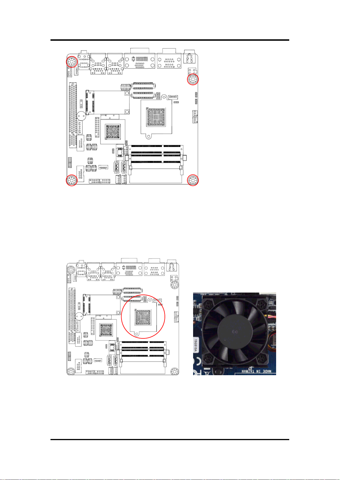
3.1.2 Screw Holes
Place four (4) screws into the holes indicated by circles to secure the motherboard to the
chassis.
Hardware Installation 21
Page 28
MANO831 Mini ITX Board
Place this side towards the
rear of the chassis.
3.2 Central Processing Unit (CPU)
The motherboard comes with onboard Intel® Atom™ D2550 processor.
3.2.1 CPU Location
Locate the CPU on the motherboard.
22 Hardware Installation
Page 29
MANO831 Mini ITX Board
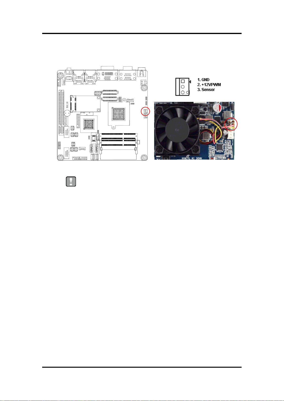
Caution
Do not forget to connect the fan cables to the fan connectors. Insufficient
air flow inside the system may damage the motherboard components.
These are not jumpers! DO NOT place jumper caps on the fan
connectors.
CPU FAN
1
3.2.2 The CPU Heatsink and Fan
Intel® Atom™ processor requires a specially designed heatsink and fan assembly to
ensure optimum thermal condition and performance.
Hardware Installation 23
Page 30

MANO831 Mini ITX Board
Channel
Socket
Single Channel
SODIMM_1
SODIMM_2
204-pin DDR3 SO-DIMM sockets
3.3 System Memory
3.3.1 Overview
The motherboard comes with two 204-pin Double Data Rate 3 (DDR3) Small Outline
Dual Inline Memory Modules (SO-DIMM) sockets.
A DDR3 module has the same physical dimensions as a DDR SO-DIMM but has a
204-pin footprint compared to the 204-pin DDR2 DIMM. DDR3 SO-DIMM is notched
differently to prevent installation on a DDR2 SO-DIMM socket. The following figure
illustrates the location of the sockets:
24 Hardware Installation
Page 31

MANO831 Mini ITX Board
Important
IF you installed two 2GB memory modules, the system may detect
less than 3GB of total memory because of address space allocation
for other critical functions. This limitation applies to Windows XP
32-bit version operating system since it does not support PAE
(Physical Address Extension) mode.
IF you install Windows XP 32-bit version operating system, we
recommend that you install less than 3GB of total memory.
Retaining clip
DDR3 SO-DIMM notch
3.3.2 Memory Configurations
You may install 1GB and 2GB unbuffered non-ECC DDR3 SO-DIMMs into the SO-DIMM
sockets using the memory configurations in this section.
3.3.3 Installing a SO-DIMM
1. Align a SO-DIMM on the socket such that the notch on the SO-DIMM matches the
break on the socket.
Hardware Installation 25
Page 32

MANO831 Mini ITX Board
Important
A DDR3 SO-DIMM is keyed with a notch so that it fits in only one
direction. DO NOT force a SO-DIMM into a socket to avoid damaging
the SO-DIMM.
The DDR3 SO-DIMM sockets do not support DDR2 SO-DIMMs. DO
NOT install DDR2 SO-DIMM to the DDR3 SO-DIMM socket.
Caution
Make sure to unplug the power supply before adding or removing
SO-DIMMs or other system components. Failure to do so may cause
severe damage to both the motherboard and the components.
DDR3 SO-DIMM notch
Retaining clip
2. Firmly insert the SO-DIMM into the socket until the retaining clips snap back in
place and the SO-DIMM is properly seated.
26 Hardware Installation
Page 33

MANO831 Mini ITX Board
Note
Support the SO-DIMM lightly with your fingers when pressing the
retaining clips. The SO-DIMM might get damaged when it flips out with
extra force.
Warning
Make sure to unplug the power cord before adding or removing expansion cards.
Failure to do so may cause you physical injury and damage motherboard
components.
DDR3 SO-DIMM notch
Retaining clip
3.3.4 Removing a SO-DIMM
1. Simultaneously press the retaining clips downward to unlock the SO-DIMM.
2. Remove the SO-DIMM from the socket.
3.4 Expansion Card
In the future, you may need to install expansion cards. The following sub-sections describe the
slots and the expansion cards that they support.
3.4.1 Installing an Expansion Card
1. Before installing the expansion card, read the documentation that came with it and
make the necessary hardware settings for the card.
2. Remove the system unit cover (if your motherboard is already installed in a
chassis).
3. Remove the bracket opposite the slot that you intend to use. Keep the screw for
later use.
4. Align the card connector with the slot and press firmly until the card is completely
seated on the slot.
5. Secure the card to the chassis with the screw you removed earlier.
6. Replace the system cover.
Hardware Installation 27
Page 34

MANO831 Mini ITX Board
3.4.2 Configuring an Expansion Card
After installing the expansion card, configure it by adjusting the software settings.
1. Turn on the system and change the necessary BIOS settings, if any. See Chapter 5
for information on BIOS setup.
2. Assign an IRQ to the card if needed.
3. Install the software drivers for the expansion card.
3.4.3 PCI Slot
This motherboard supports one PCI slot that complies with the PCI specifications. The
following figure shows an IC card installed on the PCI slot.
3.4.4 PCI-Express Mini Card Connector
This motherboard supports one PCI-Express Mini Card connector that complies with the
PCI-Express Mini Card specifications. The following figure shows a capture card
installed on this connector.
28 Hardware Installation
Page 35

MANO831 Mini ITX Board
3.4.5 CompactFlashTM Socket
This motherboard supports one CompactFlashTM card socket and its location is on
bottom side of the PCB. The following figure shows a CompactFlashTM card installed on
the CompactFlashTM socket.
Hardware Installation 29
Page 36

MANO831 Mini ITX Board
This page is intentionally left blank.
30 Hardware Installation
Page 37

MANO831 Mini ITX Board
Chapter 4
Hardware Description
4.1 Microprocessors
The MANO831 Series supports Intel® AtomTM D2550 processors, which enable your system to
operate under Windows® XP, Windows® 7 and Linux environments. The system performance
depends on the microprocessor. Make sure all correct settings are arranged for your installed
microprocessor to prevent the CPU from damages.
4.2 BIOS
The MANO831 Series uses AMI Plug and Play BIOS with a single 16Mbit SPI Flash.
4.3 System Memory
The MANO831 Series supports two 204-pin DDR3 SO-DIMM sockets for a maximum memory
of 4GB DDR3 SDRAMs. The memory module comes in sizes of 1GB and 2GB.
Hardware Description 31
Page 38

MANO831 Mini ITX Board
4.4 I/O Port Address Map
The Intel® AtomTM D2550 processors communicate via I/O ports. Total 1KB port addresses are
available for assigning to other devices via I/O expansion cards.
32 Hardware Description
Page 39

MANO831 Mini ITX Board
Hardware Description 33
Page 40

MANO831 Mini ITX Board
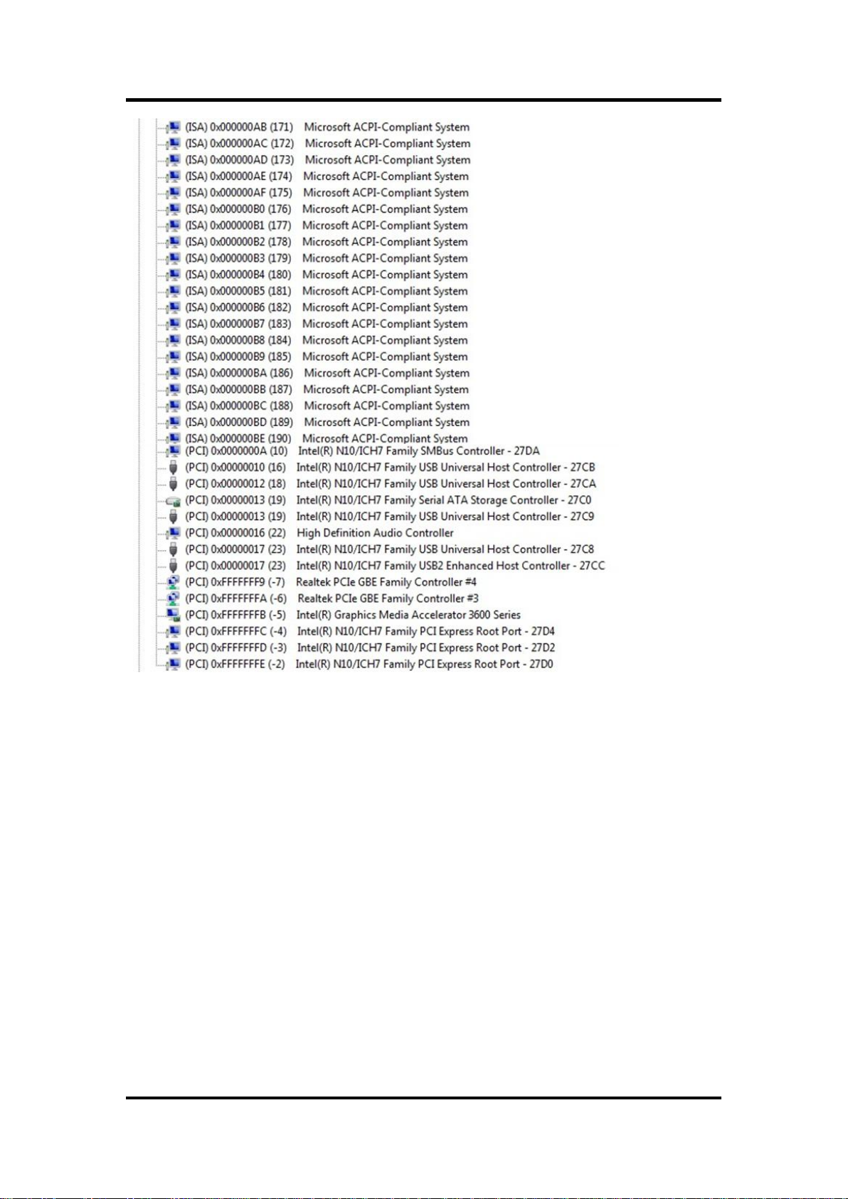
4.5 Interrupt Controller (IRQ) Map
The interrupt controller (IRQ) mapping list is shown as follows:
34 Hardware Description
Page 41
MANO831 Mini ITX Board
Hardware Description 35
Page 42
MANO831 Mini ITX Board
36 Hardware Description
Page 43
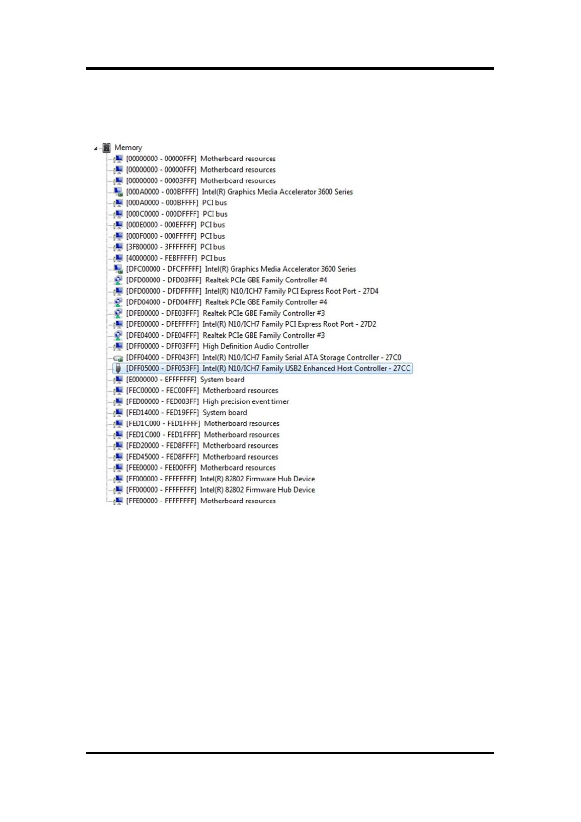
4.6 Memory Map
The memory mapping list is shown as follows:
MANO831 Mini ITX Board
Hardware Description 37
Page 44

MANO831 Mini ITX Board
This page is intentionally left blank.
38 Hardware Description
Page 45

MANO831 Mini ITX Board
Note
Some of the navigation keys differ from one screen to another.
Chapter 5
AMI BIOS Setup Utility
The AMI UEFI BIOS provides users with a built-in setup program to modify basic system
configuration. All configured parameters are stored in a flash chip to save the setup information
whenever the power is turned off. This chapter provides users with detailed description about
how to set up basic system configuration through the AMI BIOS setup utility.
5.1 Starting
To enter the setup screens, follow the steps below:
1. Turn on the computer and press the <Del> key immediately.
2. After you press the <Del> key, the main BIOS setup menu displays. You can access the
other setup screens from the main BIOS setup menu, such as the Advanced and Chipset
menus.
It is strongly recommended that you should avoid changing the chipset’s defaults. Both AMI
and your system manufacturer have carefully set up these defaults that provide the best
performance and reliability.
5.2 Navigation Keys
The BIOS setup/utility uses a key-based navigation system called hot keys. Most of the BIOS
setup utility hot keys can be used at any time during the setup navigation process. These keys
include <F1>, <F2>, <Enter>, <ESC>, <Arrow> keys, and so on.
AMI BIOS Setup Utility 39
Page 46

MANO831 Mini ITX Board
Hot Keys
Description
Left/Right
The Left and Right <Arrow> keys allow you to select a setup screen.
Up/Down
The Up and Down <Arrow> keys allow you to select a setup screen or
sub-screen.
+ Plus/Minus
The Plus and Minus <Arrow> keys allow you to change the field value of a
particular setup item.
Tab
The <Tab> key allows you to select setup fields.
F1
The <F1> key allows you to display the General Help screen.
F2
The <F2> key allows you to Load Previous Values.
F3
The <F3> key allows you to Load Optimized Defaults.
F4
The <F4> key allows you to save any changes you have made and exit
Setup. Press the <F4> key to save your changes.
Esc
The <Esc> key allows you to discard any changes you have made and exit
the Setup. Press the <Esc> key to exit the setup without saving your
changes.
Enter
The <Enter> key allows you to display or change the setup option listed for a
particular setup item. The <Enter> key can also allow you to display the
setup sub- screens.
40 AMI BIOS Setup Utility
Page 47

MANO831 Mini ITX Board
5.3 Main Menu
When you first enter the setup utility, you will enter the Main setup screen. You can always
return to the Main setup screen by selecting the Main tab. System Time/Date can be set up as
described below. The Main BIOS setup screen is shown below.
BIOS Information
Display the auto-detected BIOS information.
Intel RC Version
Intel Reference Code version.
System Language
Use this option to choose the system default language.
System Date/Time
Use this option to change the system time and date. Highlight System Time or System Date
using the <Arrow> keys. Enter new values through the keyboard. Press the <Tab> key or the
<Arrow> keys to move between fields. The date must be entered in MM/DD/YY format. The
time is entered in HH:MM:SS format.
AMI BIOS Setup Utility 41
Page 48

MANO831 Mini ITX Board
Caution
Take caution when changing the settings of the Advanced menu items. Incorrect
field values can cause the system to malfunction.
5.4 Advanced Menu
Launch PXE OpROM
Enable or disable the boot ROM function of the onboard LAN chip when the system boots
up.
The Advanced menu also allows users to set configuration of the CPU and other system
devices. You can select any of the items in the left frame of the screen to go to the sub menus:
► PCI Subsystem Settings
► ACPI Settings
► Trusted Computing
► CPU Configuration
► IDE Configuration
► USB Configuration
► Super IO Configuration
► Hardware Monitor
► Serial Port Console Redirection
► PPM Configuration
For items marked with “”, please press <Enter> for more options.
42 AMI BIOS Setup Utility
Page 49

MANO831 Mini ITX Board
PCI Subsystem Settings
You can use this screen to select options for PCI subsystem settings, and change the
value of the selected option. A description of the selected item appears on the right side of
the screen.
PCI Bus Driver Version
Display the information of PCI bus driver version.
PCI ROM Priority
In case of multiple option ROMs (Legacy and EFI Compatible), specifies what PCI option
ROM to launch.
AMI BIOS Setup Utility 43
Page 50

MANO831 Mini ITX Board
ACPI Settings
You can use this screen to select options for the ACPI configuration, and change the value
of the selected option. A description of the selected item appears on the right side of the
screen.
ACPI Sleep State
Select the ACPI sleep state the system will enter when the suspend button is pressed.
Configuration options are Suspend Disabled, S1 only (CPU Stop Clock), and S3 only
(Suspend to RAM).
Wake On LAN Control
Enable or disable Wake on LAN control.
Resume On RTC Alarm
Enable or disable system wake on alarm even. When enabled, system will wake upon the
hr/min/sec specified.
Wake On PCI PME Control
Enable or disable Wake on PCI PME control.
44 AMI BIOS Setup Utility
Page 51

MANO831 Mini ITX Board
Trusted Computing
This screen provides function for specifying the Trusted Platform Module (TPM) settings.
TPM Support
Enable or disable TPM support.
Current Status Information
Display current TPM status information.
AMI BIOS Setup Utility 45
Page 52

MANO831 Mini ITX Board
CPU Configuration
This screen shows the CPU information.
Hyper-threading
Use this item to enable or disable Hyper-Threading Technology, which makes a single
physical processor perform multi-tasking function as two logical ones.
Execute Disable Bit
Enable or disable the No-Execution Page Protection Technology.
Limit CPUID Maximum
You can enable this item to let legacy operating systems boot even without support for
CPUs with extended CPU ID functions. This item should be disabled for Windows XP.
46 AMI BIOS Setup Utility
Page 53

MANO831 Mini ITX Board
IDE Configuration
In this Configuration menu, you can see the currently installed hardware in the IDE ports.
During system boot up, the BIOS automatically detects the presence of SATA devices.
SATA Controller(s)
Enable or disable SATA controller(s).
Configure SATA as
Determine how SATA controller(s) operate. Operation mode options are IDE Mode, AHCI
Mode and RAID Mode.
AMI BIOS Setup Utility 47
Page 54

MANO831 Mini ITX Board
USB Configuration
You can use this screen to select options for the USB Configuration, and change the value
of the selected option. A description of the selected item appears on the right side of the
screen.
USB Devices
Display all detected USB devices.
Legacy USB Support
Use this item to enable or disable support for USB device on legacy operating system. The
default setting is Enabled. Auto option disables legacy support if no USB devices are
connected. Disable option will keep USB devices available only for EFI applications.
EHCI Hand-off
This is a workaround for OSes without EHCI hand-off support. The EHCI ownership
change should be claimed by EHCI driver.
USB transfer time-out
The time-out value for control, bulk and interrupt transfers.
Device reset time-out
USB mass storage device start unit command time-out.
Device power-up delay
Maximum time the device will take before it properly reports itself to the host controller.
Auto option uses default value: for a root port it is 100ms, for a hub port the delay is taken
from hub descriptor.
48 AMI BIOS Setup Utility
Page 55

MANO831 Mini ITX Board
Super IO Configuration
You can use this screen to select options for the Super IO Configuration, and change the
value of the selected option. A description of the selected item appears on the right side of
the screen. For items marked with “”, please press <Enter> for more options.
Serial Port 1~4 Configuration
Use this item to set parameters of serial port 1~4.
AC Power Loss State
Set the system power status when power returns from a power failure situation. The
system power status options are Power Off, Power On and Last State.
Watch Dog Count Mode
Set watchdog count mode.
Watch Dog Time-out Value
Set watchdog time-out value.
AMI BIOS Setup Utility 49
Page 56
MANO831 Mini ITX Board
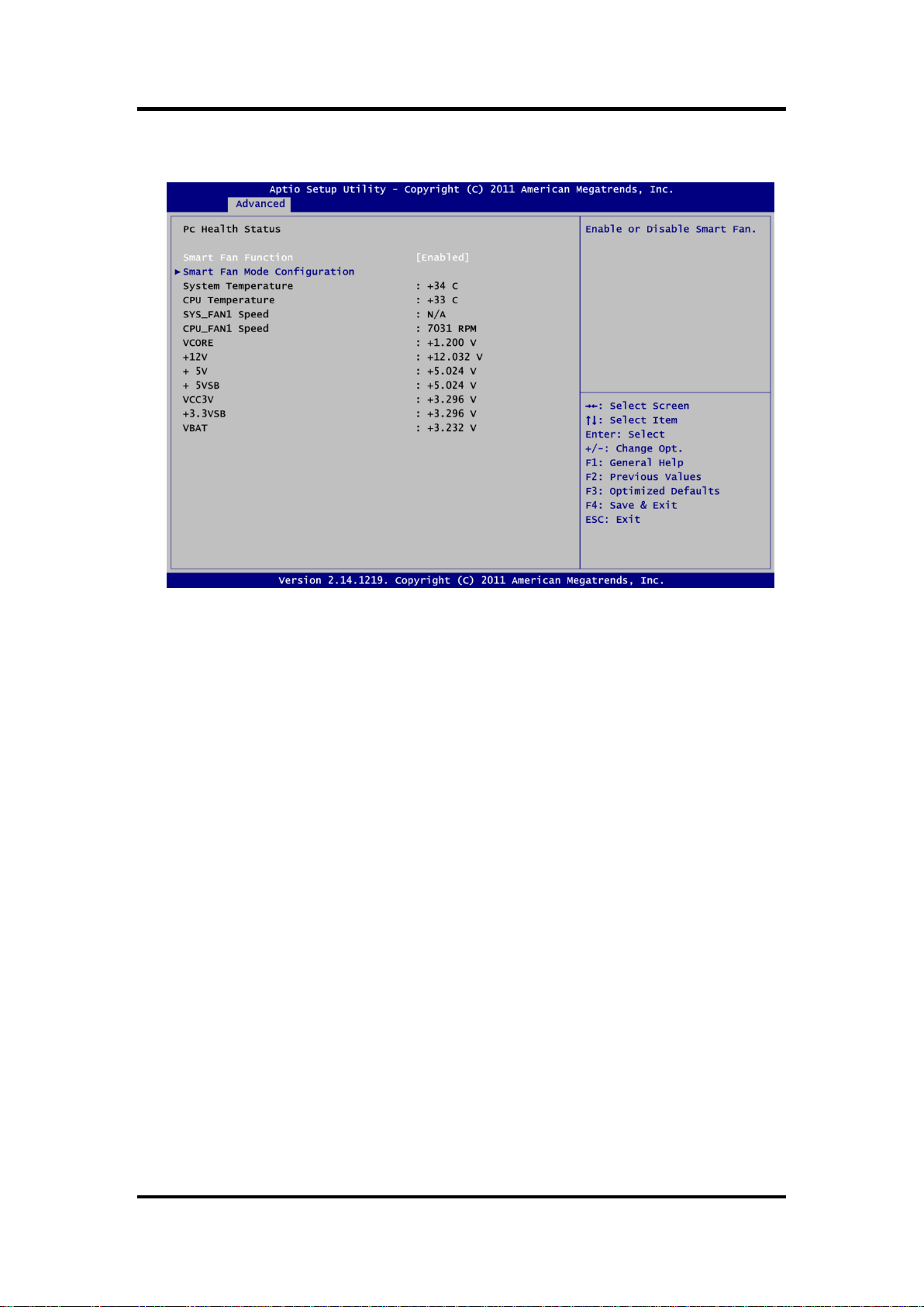
Hardware Monitor
Use this screen for Smart Fan configuration and hardware health status monitoring.
This screen displays the temperature of system and CPU, cooling fan speed in RPM and
system voltages (VCORE, +12V, +5V, +5VSB, etc).
Smart Fan Function
Enable or disable Smart Fan.
Smart Fan Mode Configuration
Use this option for Smart Fan mode configuration.
50 AMI BIOS Setup Utility
Page 57

Serial Port Console Redirection
MANO831 Mini ITX Board
Console Redirection
Enable or disable console redirection for Microsoft Windows Emergency Management
Services (EMS).
Console Redirection Settings
Display console redirection settings screen.
AMI BIOS Setup Utility 51
Page 58

MANO831 Mini ITX Board
PPM Configuration
Use this screen for PPM configuration.
CPU C state Report
Enable or disable CPU C state report to OS.
52 AMI BIOS Setup Utility
Page 59

MANO831 Mini ITX Board
5.5 Chipset Menu
The Chipset menu allows users to change the advanced chipset settings. You can select any
of the items in the left frame of the screen to go to the sub menus:
► Host Bridge
► South Bridge
For items marked with “”, please press <Enter> for more options.
AMI BIOS Setup Utility 53
Page 60
MANO831 Mini ITX Board
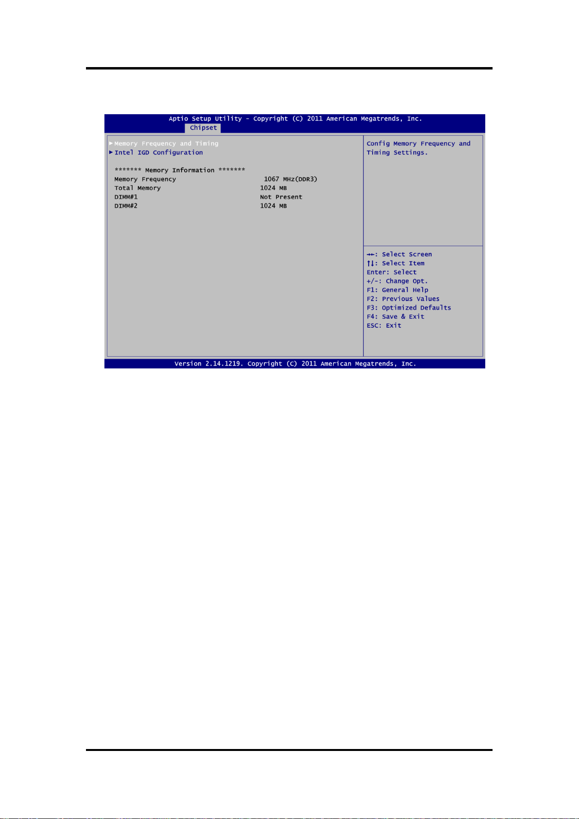
Host Bridge
This screen allows users to set Host Bridge parameters.
Memory Frequency and Timing
Display memory frequency and timing settings screen.
Intel IGD Configuration
Display internal graphics configuration screen.
Memory Information
Display detected memory information.
54 AMI BIOS Setup Utility
Page 61

Memory Frequency and Timing
MANO831 Mini ITX Board
MRC Fast Boot
Enable or disable MRC fast boot function.
Max TOLUD
Maximum value of TOLUD. Dynamic assignment would adjust TOLUD automatically
based on largest MMIO length of installed graphic controller.
AMI BIOS Setup Utility 55
Page 62

MANO831 Mini ITX Board
Intel IGD Configuration
Boot Display Type
Select the video device which will be activated during POST.
LVDS2 Control
Enable and disable LVDS2 control.
LCD Panel Type
Select LCD panel type for LVDS port.
Color Depth
Select the panel color depth. Configuration options are 18 Bit and 24 Bit.
Panel Scaling
This items allow users to set panel scaling.
Brightness Control
Select LVDS brightness control level.
56 AMI BIOS Setup Utility
Page 63

South Bridge
For items marked with “”, please press <Enter> for more options.
MANO831 Mini ITX Board
TPT Devices
Enable or disable Intel® IO controller hub (TPT) devices.
PCI Express Root Port 4
Control the PCI Express root port.
Onboard LAN1/2 Controller
Enable or disable onboard LAN1/LAN2 controller.
DMI Link ASPM Control
Enable or disable the control of Active State Power Management of the DMI Link.
High Precision Timer
Enable or disable the high precision timer
SLP_S4 Assertion Width
Set the minimum assertion width of the SLP_S4# signal to guarantee that the DRAMs
have been safely power-cycled.
AMI BIOS Setup Utility 57
Page 64

MANO831 Mini ITX Board
5.6 Boot Menu
The Boot menu allows users to change boot options of the system.
Setup Prompt Timeout
Number of seconds to wait for setup activation key. 65535(0xFFFF) means indefinite
waiting.
Bootup NumLock State
Use this item to select the power-on state for the keyboard NumLock.
Quiet Boot
Select to display either POST output messages or a splash screen during boot-up.
GateA20 Active
If Upon Request is selected, GA20 can be disabled using BIOS services. If Always is
selected, disabling G20 is not allowed; this option is useful when any RT code is executed
above 1MB.
Option ROM Messages
Set display mode for option ROM. Configuration options are Force BIOS and Keep
Current.
Interrupt 19 Capture
If this item is enabled, this function makes the option ROMs to trap Interrupt 19. The
default setting is Disabled.
CSM Support
Enable or disable CSM support.
58 AMI BIOS Setup Utility
Page 65

MANO831 Mini ITX Board
Boot Option Priorities
These are settings for boot priority. Specify the boot device priority sequence from the
available devices.
Boot Option #1..#2
These items are used to form the boot order and are dynamically generated. They
represent either a legacy BBS (BIOS Boot Specification) class of devices or a native EFI
boot entry. Press <Return> on each option to select the BBS class / EFI boot entry
desired.
CD/DVD ROM Drive BBS/Hard Drive BBS Priorities
These items are for configuring the boot order for a specific device class. These options
are only visible if at least one device for this class is detected.
AMI BIOS Setup Utility 59
Page 66

MANO831 Mini ITX Board
5.7 Security Menu
The Security menu allows users to change the security settings for the system.
Administrator Password
This item indicates whether an administrator password has been set (installed or
uninstalled).
User Password
This item indicates whether an user password has been set (installed or uninstalled).
60 AMI BIOS Setup Utility
Page 67

MANO831 Mini ITX Board
5.8 Save & Exit Menu
The Save & Exit menu allows users to load your system configuration with optimal or fail-safe
default values.
Save Changes and Exit
When you have completed the system configuration changes, select this option to leave
Setup and return to Main Menu. Select Save Changes and Exit from the Save & Exit menu
and press <Enter>. Select Yes to save changes and exit.
Discard Changes and Exit
Select this option to quit Setup without making any permanent changes to the system
configuration and return to Main Menu. Select Discard Changes and Exit from the Save &
Exit menu and press <Enter>. Select Yes to discard changes and exit.
Save Changes and Reset
When you have completed the system configuration changes, select this option to leave
Setup and reboot the computer so the new system configuration parameters can take
effect. Select Save Changes and Reset from the Save & Exit menu and press <Enter>.
Select Yes to save changes and reset.
Discard Changes and Reset
Select this option to quit Setup without making any permanent changes to the system
configuration and reboot the computer. Select Discard Changes and Reset from the Save
& Exit menu and press <Enter>. Select Yes to discard changes and reset.
Save Changes
When you have completed the system configuration changes, select this option to save
changes. Select Save Changes from the Save & Exit menu and press <Enter>. Select Yes
to save changes.
AMI BIOS Setup Utility 61
Page 68

MANO831 Mini ITX Board
Discard Changes
Select this option to quit Setup without making any permanent changes to the system
configuration. Select Discard Changes from the Save & Exit menu and press <Enter>.
Select Yes to discard changes.
Restore Defaults
It automatically sets all Setup options to a complete set of default settings when you select
this option. Select Restore Defaults from the Save & Exit menu and press <Enter>.
Save as User Defaults
Select this option to save system configuration changes done so far as User Defaults.
Select Save as User Defaults from the Save & Exit menu and press <Enter>.
Restore User Defaults
It automatically sets all Setup options to a complete set of User Defaults when you select
this option. Select Restore User Defaults from the Save & Exit menu and press <Enter>.
Boot Override
Select a drive to immediately boot that device regardless of the current boot order.
62 AMI BIOS Setup Utility
 Loading...