

Page 1

FDK172-834
Open Frame Display
PANEL PC
User’s Manual
Page 2

Disclaimers
This manual has been carefully checked and believed to contain accurate information.
Axiomtek Co., Ltd. assumes no responsibility for any infringements of patents or any third
party’s rights, and any liability arising from such use.
Axiomtek does not warrant or assume any legal liability or responsibility for the accuracy,
completeness or usefulness of any information in this document. Axiomtek does not make any
commitment to update the information in this manual.
Axiomtek reserves the right to change or revise this document and/or product at any time
without notice.
No part of this document may be reproduced, stored in a retrieval system, or transmitted, in
any form or by any means, electronic, mechanical, photocopying, recording, or otherwise,
without the prior written permission of Axiomtek Co., Ltd.
CAUTION
If you replace wrong batteries, it causes the danger of explosion. It is recommended by the
manufacturer that you follow the manufacturer’s instructions to only replace the same or
equivalent type of battery, and dispose of used ones.
Copyright 2015 Axiomtek Co., Ltd.
All Rights Reserved
Apr 2015, Version A1
Printed in Taiwan
ii
Page 3

Safety Precautions
Before getting started, read the following important cautions.
1. Be sure to ground yourself to prevent static charge when installing the internal
components. Use a grounding wrist strap and place all electronic components in any
static-shielded devices. Most electronic components are sensitive to static electrical
charge.
2. Disconnect the power cords from the FDK191 Series before making any installation. Be
sure both the system and the external devices are turned OFF. Sudden surge of power
could ruin sensitive components. Make sure the NA-550 Series is properly grounded.
3. Do not open the system’s top cover. If opening the cover for maintenance is a must, only
a trained technician is allowed to do so. Integrated circuits on computer boards are
sensitive to static electricity. To avoid damaging chips from electrostatic discharge,
observe the following precautions:
Before handling a board or integrated circuit, touch an unpainted portion of the
system unit chassis for a few seconds. This will help to discharge any static
electricity on your body.
When handling boards and components, wear a wrist-grounding strap, available
from most electronic component stores.
Trademarks Acknowledgments
Axiomtek is a trademark of Axiomtek Co., Ltd.
Windows® is a trademark of Microsoft Corporation.
IBM, PC/AT, PS/2, VGA are trademarks of International Business Machines Corporation.
Intel® and Pentium® are trademarks of Intel Corporation.
AMI is trademark of American Megatrend Inc.
Other brand names and trademarks are the properties and registered brands of their
respective owners.
iii
Page 4

Table of Contents
Disclaimers ..................................................................................................... ii
Safety Precautions ........................................................................................ iii
Chapter 1 Introduction ............................................. 1
1.1 General Description ............................................................................ 1
1.2 Specifications ...................................................................................... 2
1.3 Dimensions and Outlines ................................................................... 4
1.4 I/O Outlets ............................................................................................ 5
1.5 Packing List ......................................................................................... 6
Chapter 2 Hardware and Installation ...................... 7
2.1 Open and close back cover ................................................................ 8
2.2 CF card Installation ........................................................................... 10
2.3 Serial Ports Interface ........................................................................ 10
2.3.1 COM port Connector .................................................................................. 11
2.4 Ethernet .............................................................................................. 12
2.5 Mountings: Openframe/VESA .......................................................... 13
2.5.1 Openframe Mount ..................................................................................... 13
2.5.2 VESA Mounting ......................................................................................... 14
2.6 HDD Installation ................................ ................................................. 15
2.7 DRAM Installation .............................................................................. 17
2.8 Mini cards installation ....................................................................... 18
2.8.1 Wireless LAN card installation .................................................................. 18
2.8.2 mSATA Card Installation ............................................................................ 20
2.9 SBC87834 Jumpers and Connectors............................................... 21
2.9.1 Jumper Settings ........................................................................................ 23
2.9.2 Connectors ................................................................................................ 24
Chapter 3 AMI BIOS Setup Utility .......................... 35
3.1 Navigation Keys ................................................................................ 35
3.2 Main Menu .......................................................................................... 36
3.3 Advanced Menu ................................................................................. 37
3.4 Chipset Menu ..................................................................................... 46
3.5 Security .............................................................................................. 49
iv
Page 5

3.6 Boot Menu .......................................................................................... 50
3.7 Save&Exit ........................................................................................... 51
Chapter 4 Drivers Installation .............................. 53
4.1 System ............................................................................................... 53
4.1.1 Win 7 ......................................................................................................... 53
4.1.2 Win 8/8.x ................................................................................................... 54
4.2 Touch Screen ..................................................................................... 54
4.2.1 Specification .............................................................................................. 54
4.2.2 Driver Installation- Windows 7/8.x ............................................................. 55
4.3 Embedded O.S. .................................................................................. 57
4.3.1 WES 7 & WE8S ......................................................................................... 57
Appendix A Watchdog Timer ................................... 59
About Watchdog Timer ................................................................................ 59
How to Use Watchdog Timer ....................................................................... 59
WDT Sample Program ................................................................................. 60
Appendix B Backlight Control ................................. 63
About Backlight Control .............................................................................. 63
How to Use Backlight Control ..................................................................... 63
Removed Brightness Control Tool ............................................................. 72
v
Page 6

This page is intentionally left blank.
vi
Page 7

FDK172-834 User’s Manual
Chapter 1
Introduction
This chapter contains general information and detailed specifications of the FDK172-834
series. Chapter 1 includes the following sections:
General Description
Specification
Dimensions
I/O Outlets
Package List
1.1 General Description
The FDK series is an open frame touch panel computer, equipped with a 17-inch TFT LCD
display and low power consumption Intel® AtomTM processor J1900 2.0 GHz. The panel
computer is able to install a CompactFlash™ card and provide a Mini card slot for wireless
module. This slim series is designed for immediate integration and can be widely deployed in
indoor kiosk, HMI automation, and many more applications. Its slim ID can fits into any space
or encased in any chassis. FDK172-834 comes with a front panel open frame design.
Other than offering above configuration advantages, this open frame panel computer series
also highlights an ultra slim profile and compact footprint in thickness. Moreover, the
brightness adjustment knob located on the back cover makes maintenance easier and faster.
For WiFi & 3G connection, this slim unit incorporates a Mini Card slot for expansion capability.
FDK172-834 utilizes one 204-pin DDR3 1066 SODIMM system memory max. up to 8GB, one
SATA HDD and one CFast or mSATA. It provides over-current protection-fuse and a full set of
I/O including VGA, RS-232, RS-232/422/485, USB 2.0, audio (line-out), and Gigabit Ethernet.
Introduction 1
Page 8

FDK172-834 User’s Manual
1.2 Specifications
Main CPU Board
CPU
Intel
System Memory
One 204-pin DDR3L 1333MHz SO-DIMM socket
Maximum memory up to 8GB
BIOS
America Megatrends BIOS
I/O System
Standard I/O
2 x RS-232/422/485, 2 x RS232
2 x USB 2.0, 2 x USB 3.0
1 x VGA
Ethernet
1 x INTEL I210IT RJ45 for Giga Ethernet
Audio
1x Line-out
Expansion
2 x Full size Mini-card slot
Storage
1 x 2.5” SATA HDD
1 x Cfast or 1 x mSATA
Power connector
12V DC power jack type, 24V DC phoenix type
Note: When FDK172-832 connects to display via VGA port, LVDS will be turned off and shown
on VGA display during start the system. After installing graphics driver, FDK172-834 will have
dual display.
®
AtomTM J1900 2.00GHz processor onboard
2 Introduction
Page 9

System Specification
17” SXGA(1280x1024) TFT LCD
Touch (equip on FDK172-834-R models)
5-wired resistive touch
Heat Dispensing Design
Disk drive housing
One 2.5” SATA drive
Net Weight
5.52 Kgs (12.16 lb)
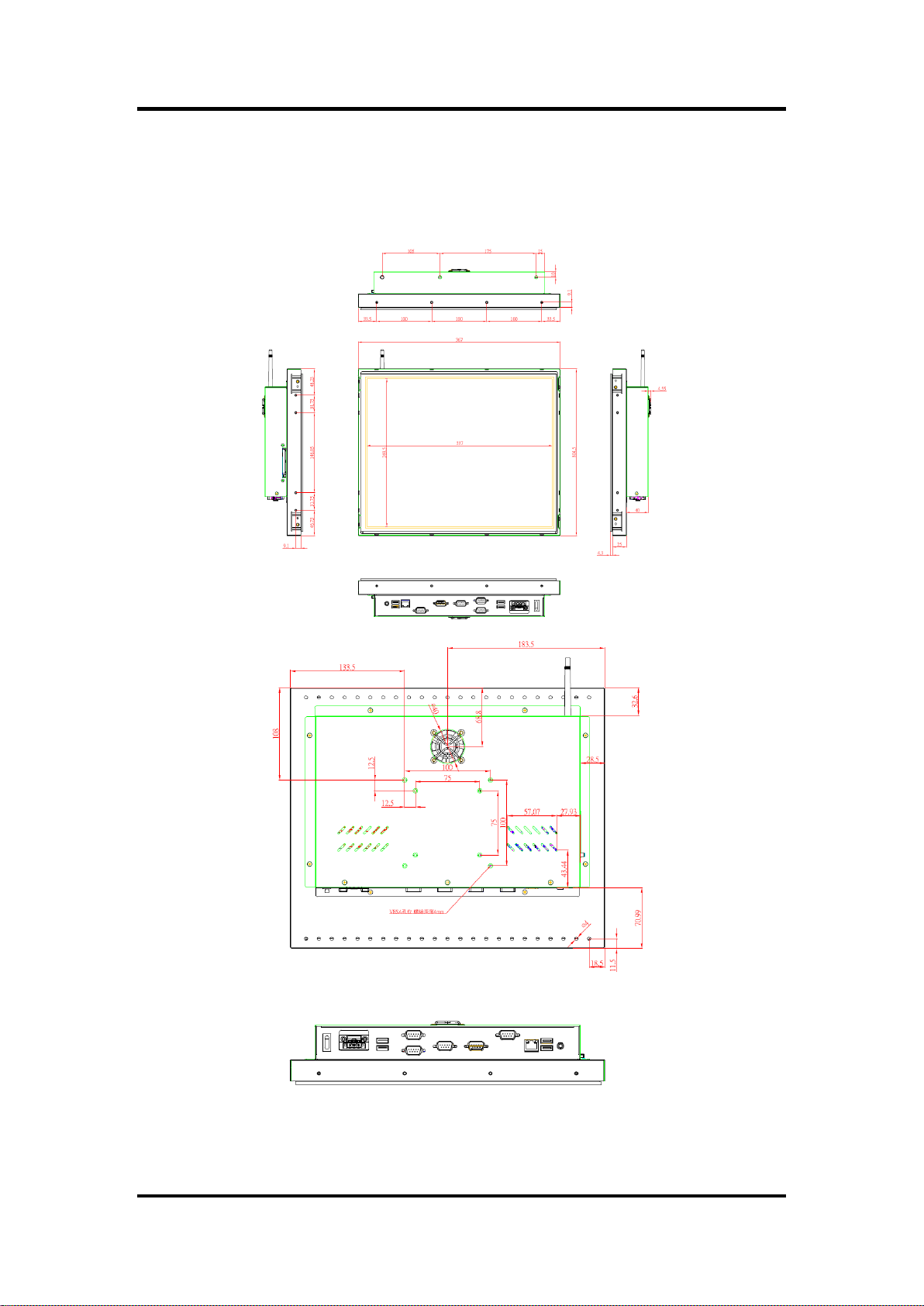
Dimension (Main Body Size)
367x 65x 304.5 mm
Operation Temperature
0℃ to 50℃
Relative Humidity
10% to 90% @ 40℃, Non-Condensing
Power input
12/24VDC with phoenix power connector
FDK172-834 User’s Manual
NOTE All specifications and images are subject to change without notice.
NOTE If the operation temperature is higher than 40℃, the wide temperature
DRAM/HDD/CF are recommended to be used on the device.
NOTE LVDS is the primary display.
Introduction 3
Page 10
FDK172-834 User’s Manual
1.3 Dimensions and Outlines
The following diagrams show the dimensions and outlines of FDK172-834.
4 Introduction
Page 11
FDK172-834 User’s Manual
No
Function
No
Function
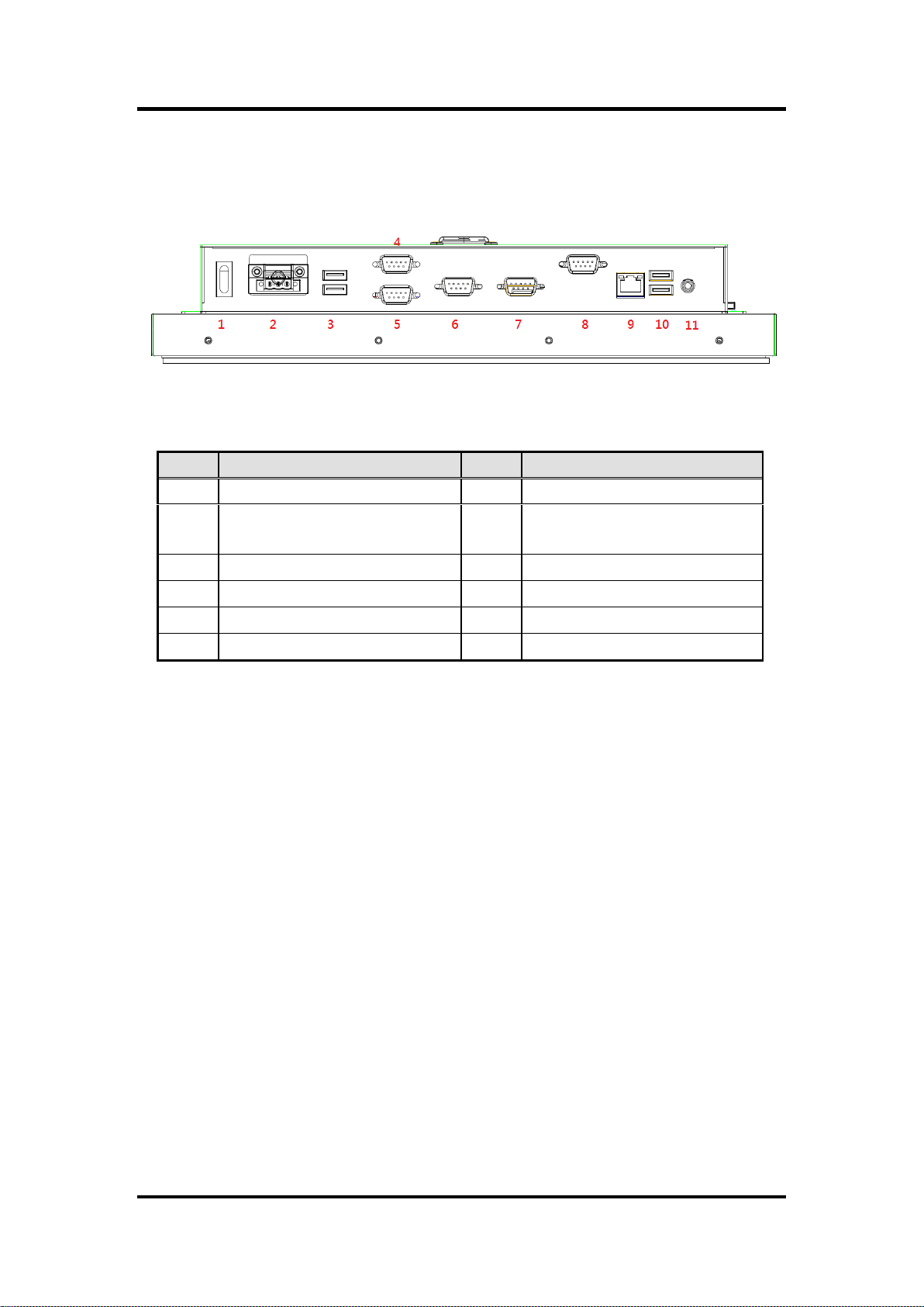
1
POWER SWITCH (ATX)
7
COM 2 (RS-232/422/485)
2
1 x 12VDC Power input connector or
24V DC phoenix connector
8
1 X VGA
3
2 X USB 2.0
9
1 X ETHERNET (RJ-45)
4
COM 3 (RS-232)
10
2 X USB 3.0
5
COM 4 (RS-232)
11
1 X AUDIO (LINE-OUT)
6
COM 1 (RS-232/422/485)
1.4 I/O Outlets
Please refer to the following illustration for I/O locations of the FDK172-834.
Introduction 5
Page 12

FDK172-834 User’s Manual
1.5 Packing List
When you receive the FDK172-834, the bundled package should contain the following items:
FDK172-834 unit x 1
Driver CD x1
Power adaptor x 1 (for 12V DC Power Jack type only)
Phoenix terminal x 1 (for phoenix type only)
If you can not find the package or any items are missing, please contact Axiomtek distributors
immediately.
6 Introduction
Page 13

FDK172-834 User’s Manual
Chapter 2
Hardware and Installation
The FDK172-834 provides rich I/O ports and flexible expansions for you to meet different
demand, for example CF card. The chapter will show you how to install the hardware. It
includes:
Open and close back cover
CompactFlash™ Card
Serial Port
Ethernet
Mounting Method
Hard disk
DRAM
Wireless LAN Card
SBC87834 jumpers and connectors
Hardware and Installation 7
Page 14
FDK172-834 User’s Manual
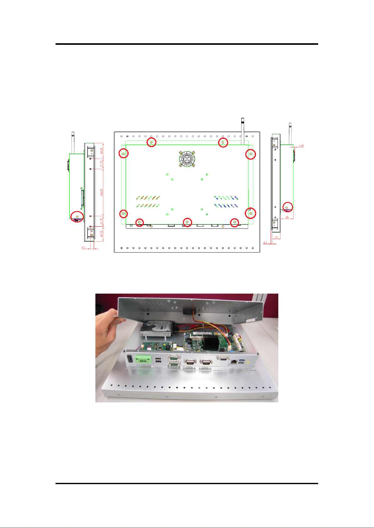
2.1 Open and close back cover
This section tells users how to open and close the back cover. Please follow the steps below.
Step 1 Unscrew eleven screws on the back cover. Please refer the photo of top side,
right side and left side.
Step 2 When users open the back cover, there is a cable connecting between a fan
and the motherboard.
8 Hardware and Installation
Page 15
FDK172-834 User’s Manual
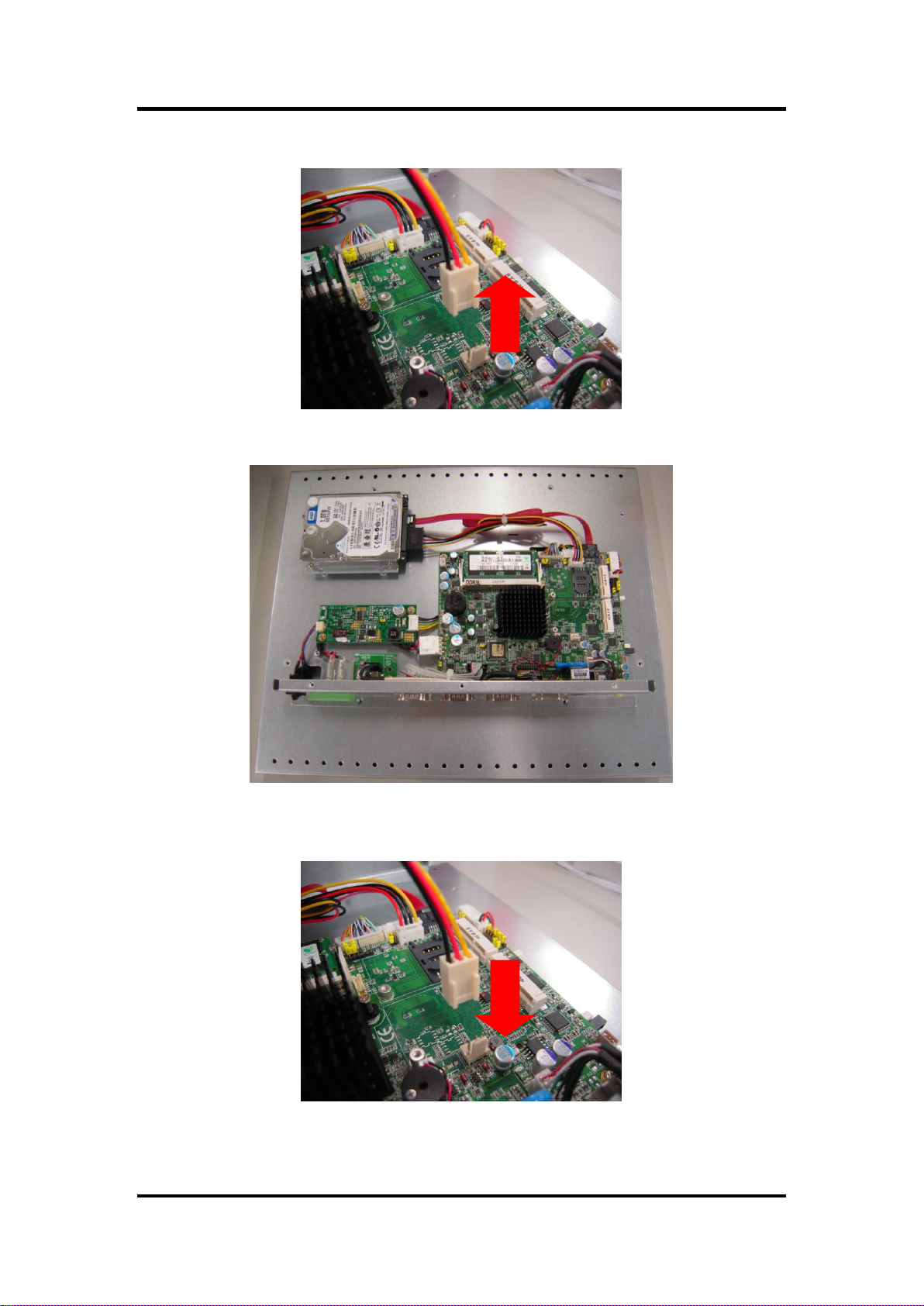
Step 3 Remove the connector first before remove the back cover totally.
Step 4 After removing the back cover, users can see the inside of the unit.
Step 5 Before closing the back cover, users must connect the fan cable to the
motherboard first.
Step 6 Then close back cover and fix back the eleven screws.
Hardware and Installation 9
Page 16
FDK172-834 User’s Manual
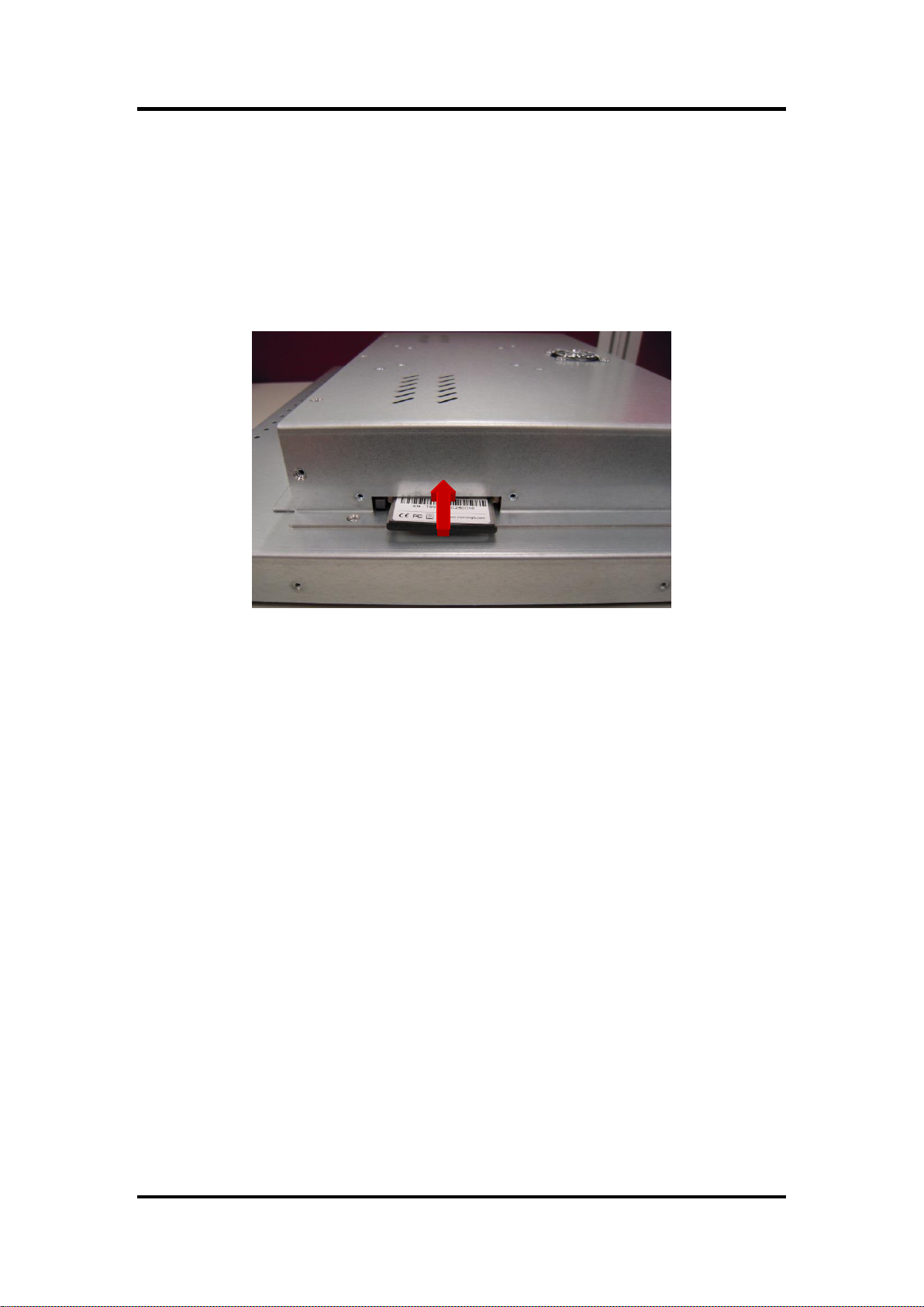
2.2 CF card Installation
The FDK172-834 provides one CF slot for users to install CompactFlash™ card. Please refer
to the following instructions for installation:
Step 1 Turn off the system, and unplug the power cord.
Step 2 Locate the CompactFlashTM socket, and insert the card into the socket.
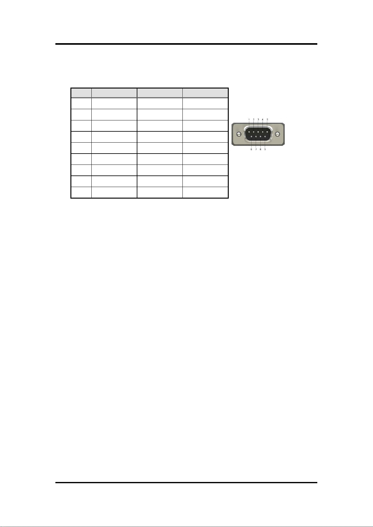
2.3 Serial Ports Interface
The FDK172-834 has four serial ports. COM1 and COM2 are RS-232/422/485, while COM3
and COM4 are RS-232.
10 Hardware and Installation
Page 17
FDK172-834 User’s Manual
Pin
RS-232
RS-422
RS-485
1
DCD
TX-
Data-
2
RXD
TX+
Data+
3
TXD
RX+
No use
4
DTR
RX-
No use
5
GND
GND
GND
6
DSR
No use
No use
7
RTS
No use
No use
8
CTS
No use
No use
9
RI
No use
No use
2.3.1 CO M port Connector
The pin assignment of RS-232/RS-422/RS-485 is listed on the following table.
Hardware and Installation 11
Page 18
FDK172-834 User’s Manual
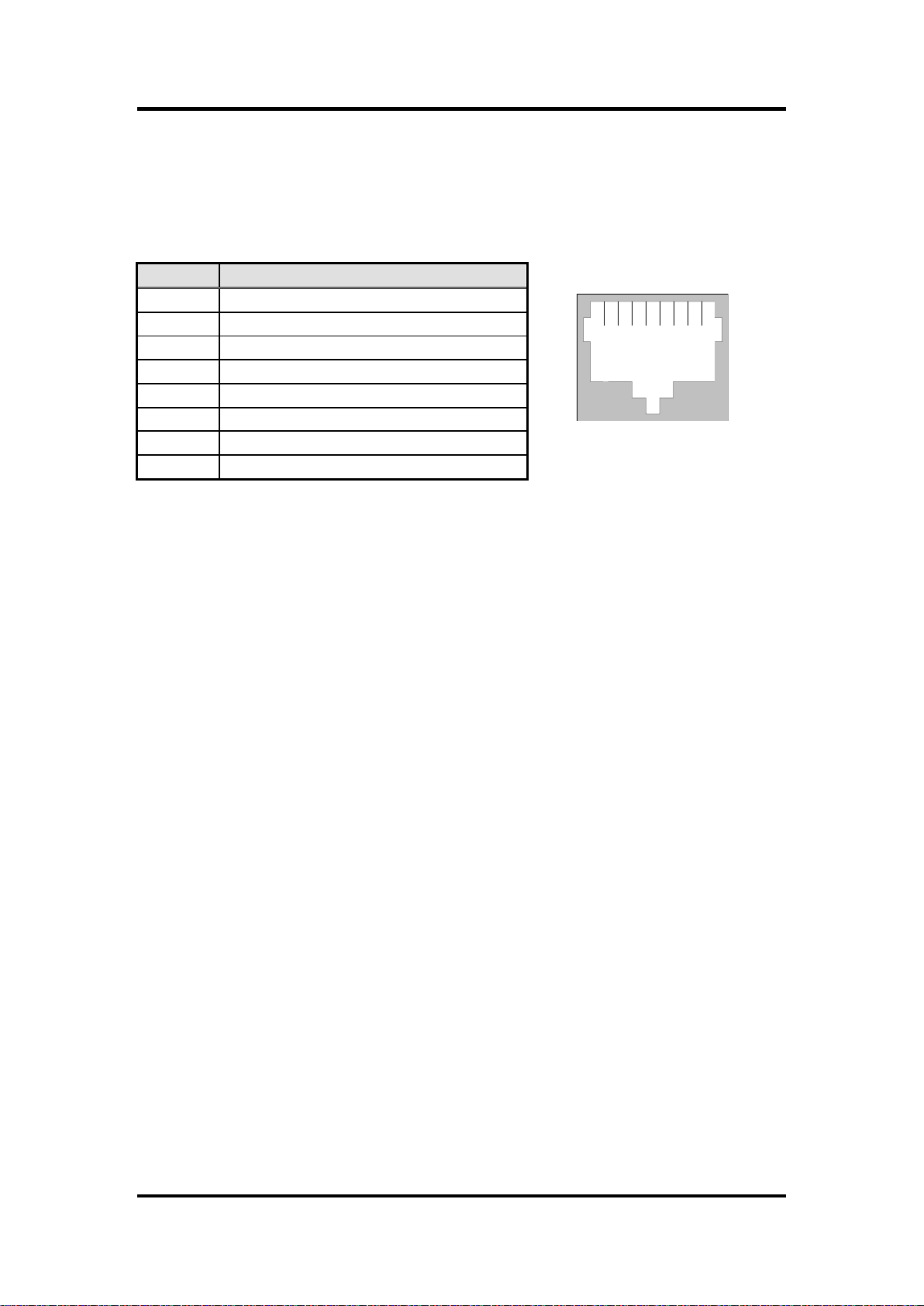
Pin
Signal
1234567
8
RJ-45
1
TX+ (Data transmission positive
2
TX- (Data transmission negative)
3
Rx+(Data reception positive)
4
RJ45 termination
5
RJ45 termination
6
Rx- (Data reception negative)
7
RJ45 termination
8
RJ45 termination
2.4 Ethernet
The FDK172-834 is equipped with a high performance Plug and Play Ethernet interface, full
compliant with IEEE 802.3 standard, and can be connected with a RJ-45 LAN connector.
Please refer to detailed pin assignment list below:
12 Hardware and Installation
Page 19
FDK172-834 User’s Manual
2.5 Mountings: Openframe/VESA
There are two mounting ways for the FDK172-834 series, openframe and VESA mountings.
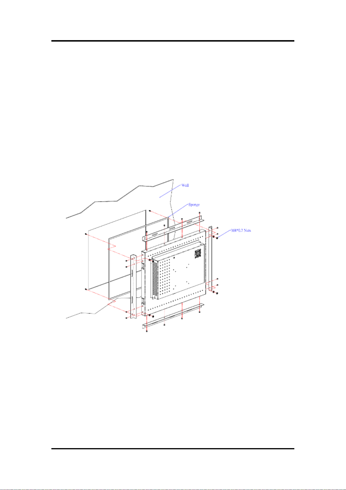
2.5.1 Openframe Mount
The FDK172-834 series can be mounted into the wall or put on customized front bezel.
Please follow the steps below to for the open frame mounting installation.
Step 1 Users need to prepare the front bezel/wall, screws, nuts, sponge, and
L-type holders by themselves.
Step 2 Follow section 1.4 dimensions and drawing below. Place the
FDK172-834 unit on the front bezel or wall.
Step 3 Screw the FDK172-834 to fix it.
Hardware and Installation 13
Page 20
FDK172-834 User’s Manual
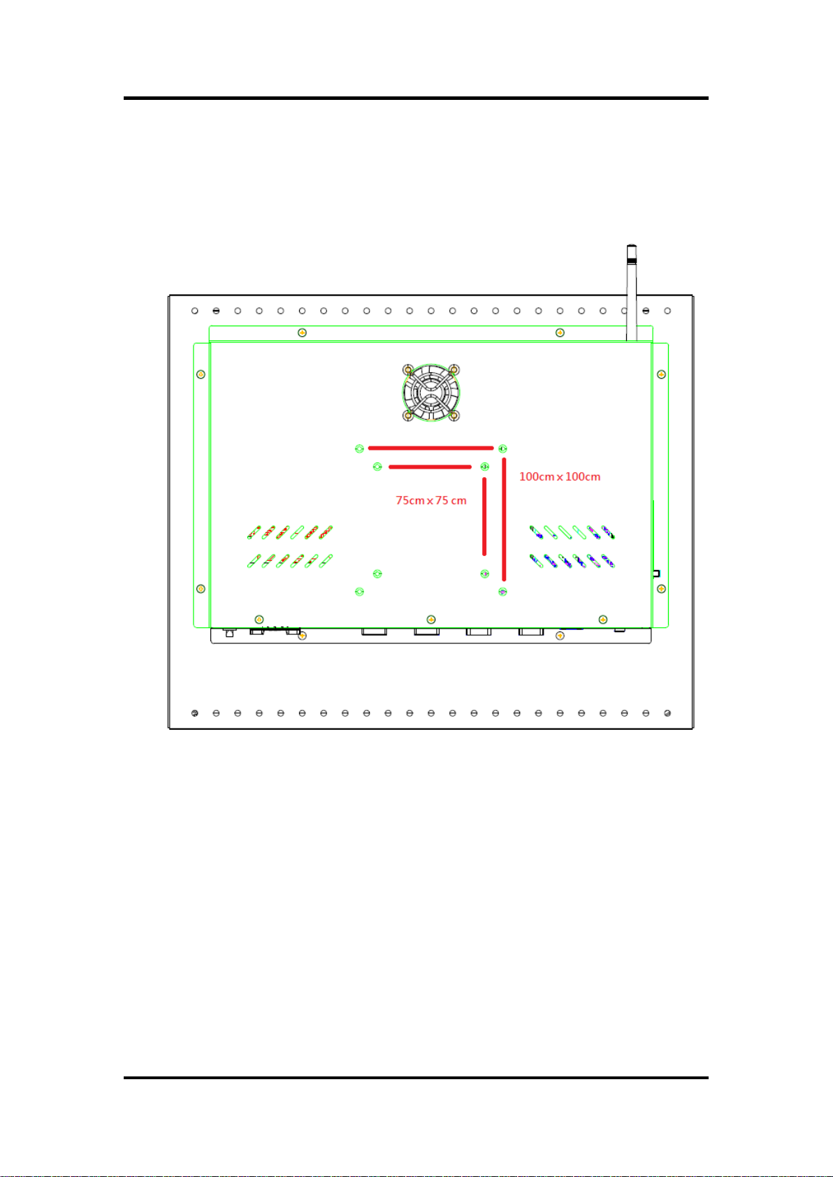
2.5.2 VESA Mounting
FDK172-834 series provides two types of VESA holes, 75mm x 75mm and 100mm x
100mm. These VESA holes can easy for users to install FDK172-834 series via many
different types of VESA mounting holders, such as VESA arm, VESA wall holders…etc.
14 Hardware and Installation
Page 21
FDK172-834 User’s Manual
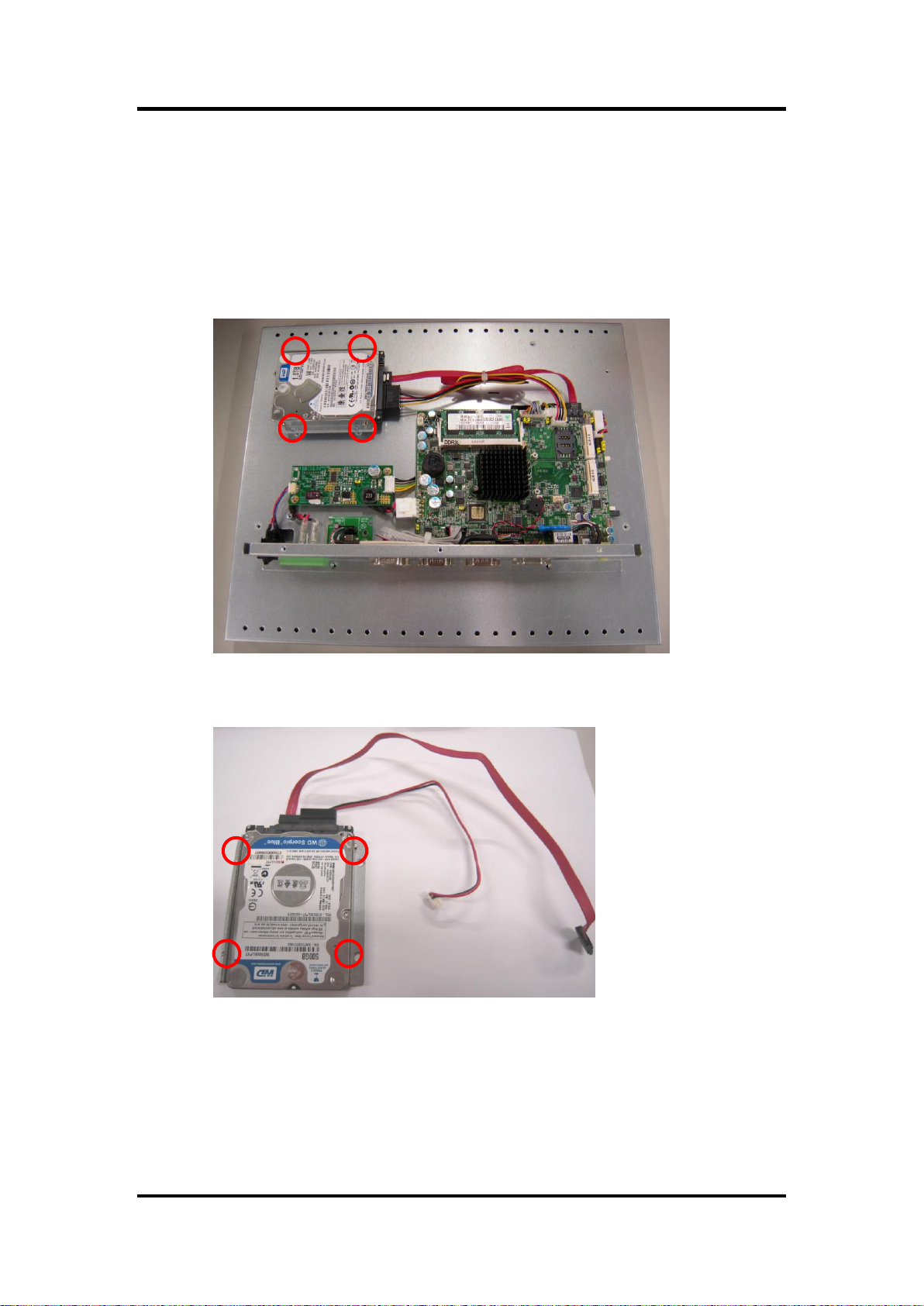
2.6 HDD Installation
The FDK172-834 provides a convenient Hard Disk Drive (HDD) bracket for users to install 2.5”
SATA HDD. Please follow the steps:
Step 1 Refer section 2.1 to open the back cover.
Step 2 Unscrew 4 screws to take off the HDD bracket.
Step 3 Fix the HDD on bracket by 4 screws, and connect SATA cable as well as
power cable.
Hardware and Installation 15
Page 22
FDK172-834 User’s Manual
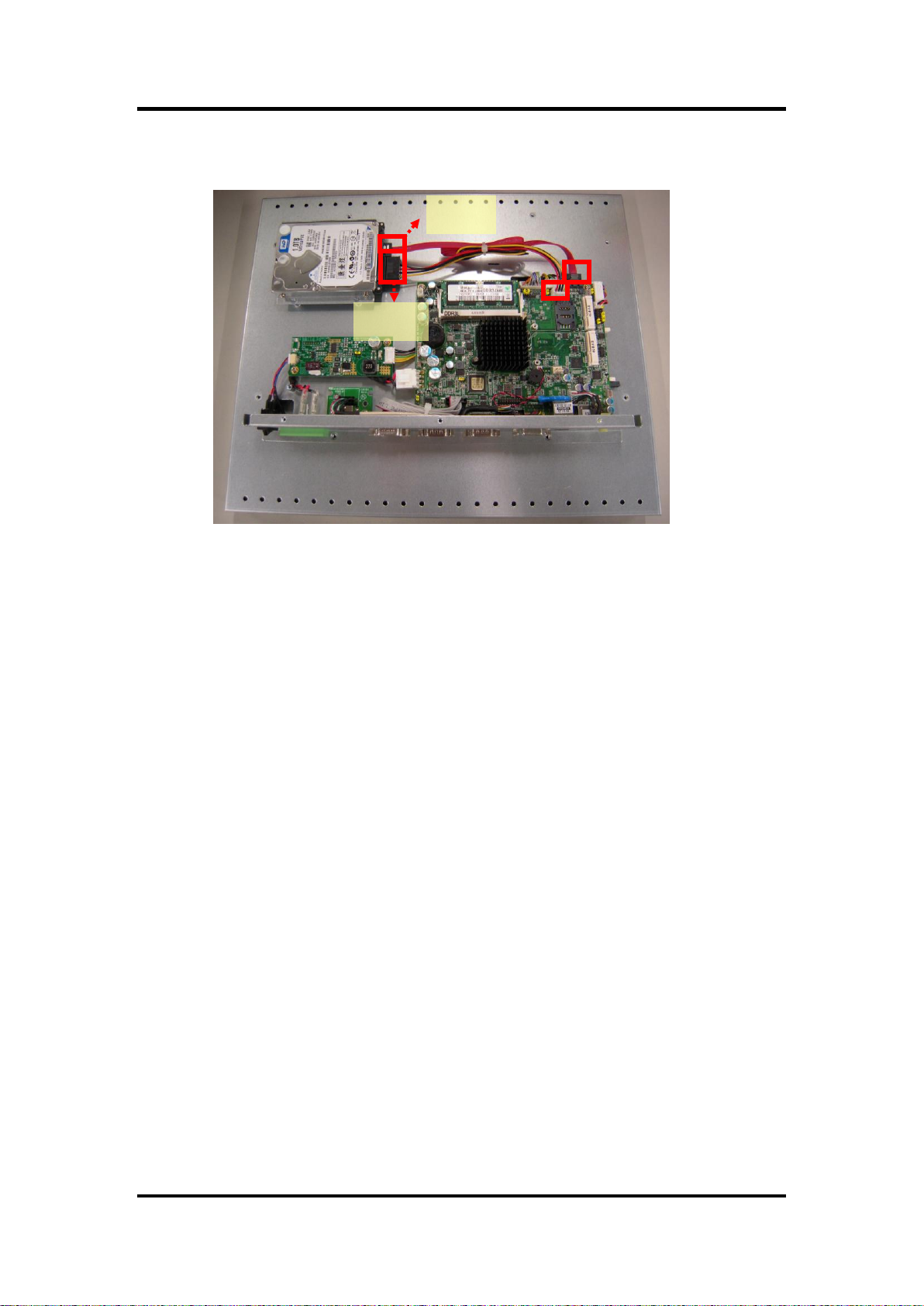
Data
Power
Step 4 Fix the HDD bracket into the system, and plug the data and power cable to
HDD. Installation completes.
16 Hardware and Installation
Page 23
FDK172-834 User’s Manual
1
2
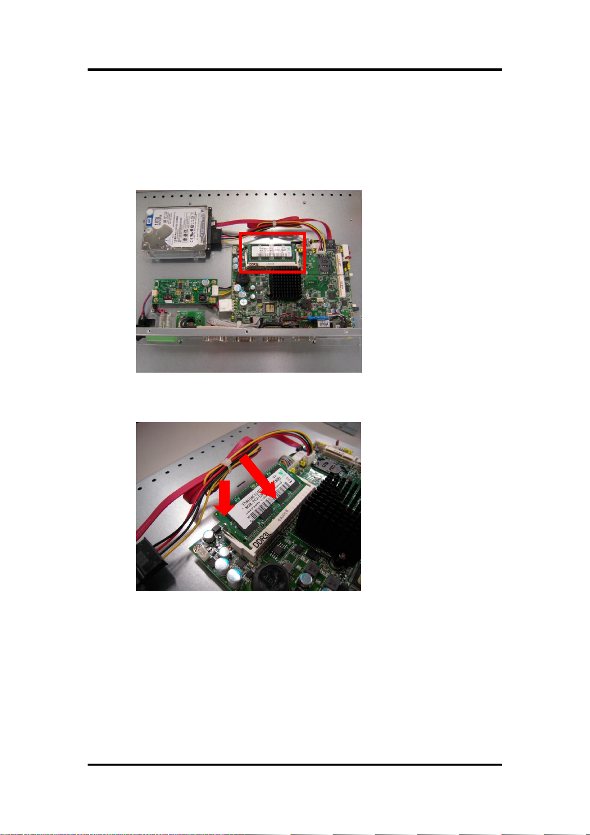
2.7 DRAM Installation
The FDK172-834 provides one 204-pin DDR3 SODIMM socket that support system memory
up to 4GB. Please follow steps below to install the memory modules:
Step 1 Refer to section 2.1 to open the back cover and find out DIMM socket on
mainboard (SBC87832).
Step 2 Insert the DRAM to the DIMM socket, and then push it down firmly until it is
clipped by the socket.
Step 3 Installation completes.
Hardware and Installation 17
Page 24
FDK172-834 User’s Manual
slot1
slot2
2.8 Mini cards installation
2.8.1 Wireless LAN card installation
The FDK172-834 provides two Mini card slots for user to install wireless LAN cards. You
can choose either slot 1 or slot 2 to install the wireless LAN card and refer to the following
instructions and illustration:
Step 1 Refer to section 2.1 to open the back cover and find out mini-card slot on
mainboard.
Step 2 Insert the wireless LAN card to the slot. Push it down firmly until it is
clipped by the slot.
18 Hardware and Installation
Page 25
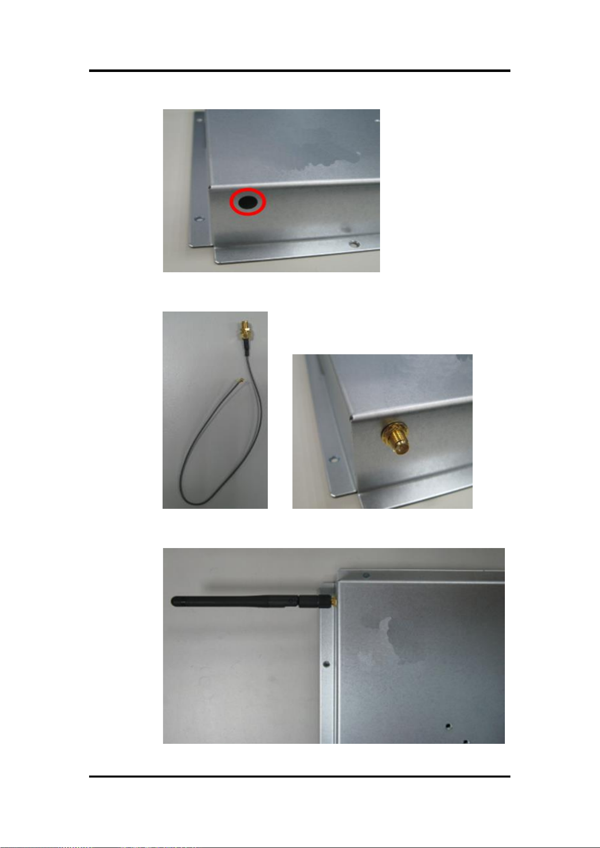
Step 3 Remove the antenna plug from the top of back cover.
Step 4 Install the antenna cable on the back cover.
FDK172-834 User’s Manual
Step 5 Install the antenna on the antenna connector.
Hardware and Installation 19
Page 26

FDK172-834 User’s Manual
slot1
slot2
Step 6 Connect the antenna cable to wireless LAN card.
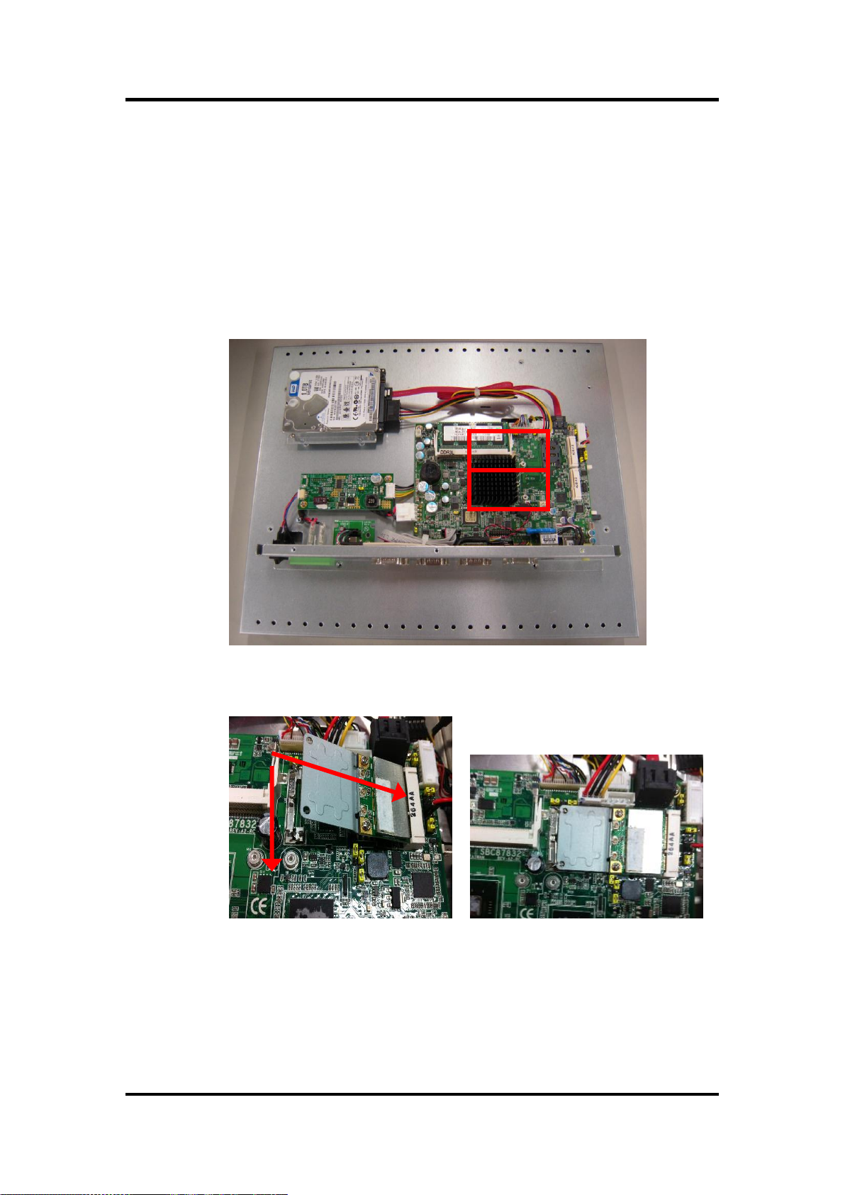
2.8.2 mSATA Card Installation
The FDK172-834 provides one Mini card slot for user to install mSATA. Please choose
the slot 2 when installing the mSATA card and refer to the following instructions and
illustration:
Step 1 Refer to section 2.1 to open the back cover and find out mini-card slot on
mainboard.
Step 2 Insert the mSATA card to the slot 2. Screw it firmly on the slot.
NOTE Please set the jumper JP6 in 2-3 when using the mSATA.
NOTE The screws of mini card slots are M12 type.
NOTE CFast or mSATA only can be chosen one of each for storage.
20 Hardware and Installation
Page 27

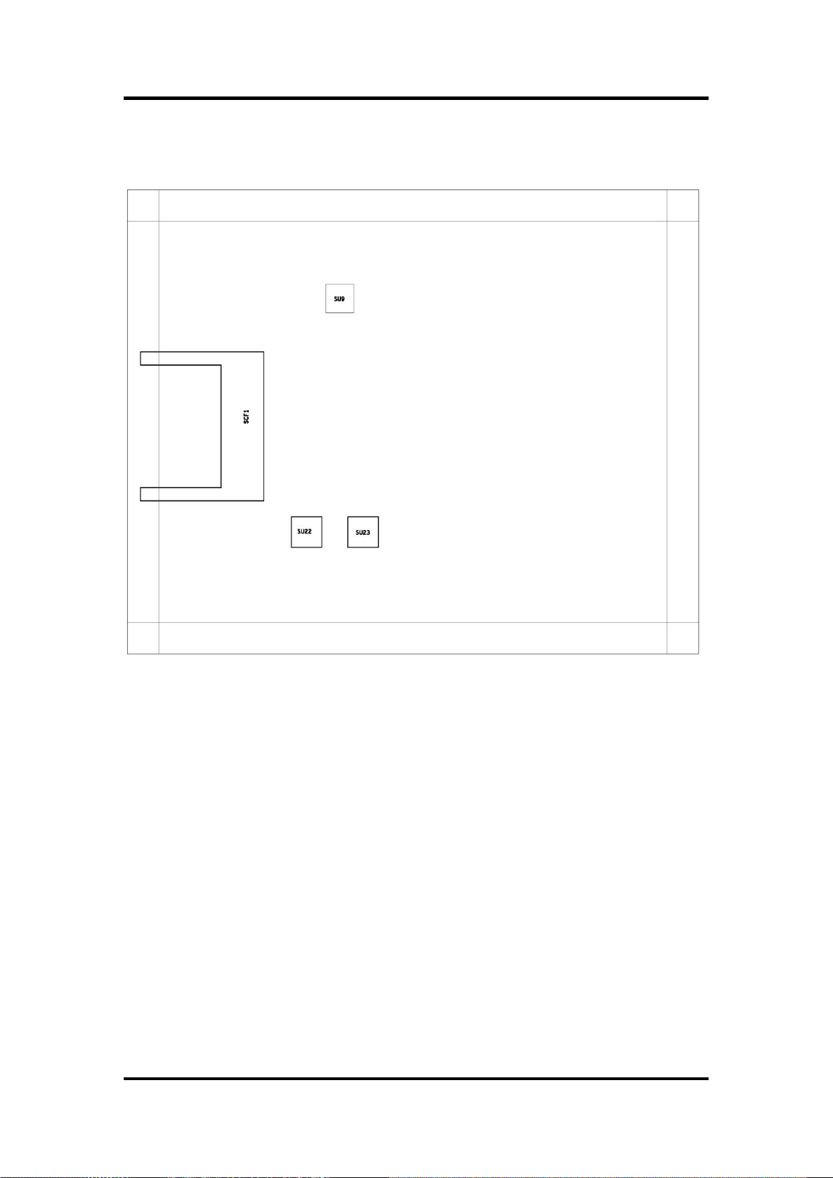
2.9 SBC87834 Jumpers and Connectors
Component Side
FDK172-834 User’s Manual
Hardware and Installation 21
Page 28
FDK172-834 User’s Manual
Solder Side
22 Hardware and Installation
Page 29

FDK172-834 User’s Manual
Jumper
★ Default Setting
Jumper Setting
JP1
★ Panel backlight control PWM mode
Panel backlight control DC mode
Short 1-2
Short 3-4
JP2
Touch Controller 4,8 WIRE
★ Touch Controller 5 WIRE
Short 1-2
Short 2-3
JP4
★ LVDS Panel Power : 3.3V
LVDS Panel Power : 5V
Short 1-2
Short 2-3
JP5
Touch OFF
★ Touch ON
Short 1-2
Short 2-3
JP6
★ PCIe device
mSATA device
Short 1-2
Short 2-3
JP7
AT mode
★ ATX mode
Short 1-2
Short 2-3
JP8
★ Normal
Clear CMOS
Short 1-2
Short 2-3
JP11
COM3_5VSB
★ COM3_5V
Short 1-2
Short 2-3
JP12
★ COM1 normal mode
COM1 pin1 with power :+5V
COM1 pin9 with power :+12V
Short 3-5,4-6
Short 1-3,4-6
Shot 3-5,2-4
JP13
★ COM2 normal mode
COM2 pin1 with power :+5V
COM2 pin9 with power :+12V
Short 3-5,4-6
Short 1-3,4-6
Shot 3-5,2-4
JP14
★ COM3 normal mode
COM3 pin1 with power :+5V
COM3 pin9 with power :+12V
Short 3-5,4-6
Short 1-3,4-6
Shot 3-5,2-4
JP15
★ COM4 normal mode
COM4 pin1 with power :+5V
COM4 pin9 with power :+12V
Short 3-5,4-6
Short 1-3,4-6
Shot 3-5,2-4
2.9.1 Jumper Settings
Making the proper jumper settings configure the SBC87834 to match the needs of your
application.
The following table shows the default jumper settings for the onboard devices.
Hardware and Installation 23
Page 30

FDK172-834 User’s Manual
Connectors
Label
LVDS connector
CN1
LVDS inverter connector
CN2
TOUCH connector
CN3
HDD power connector
CN4
Full size min-PCIe connector
CN5
FRONT PANEL pin header
CN6
SIM card connector
CN7
Full size min-PCIe connector
CN8
DC IN connector
CN9
Digital I/O pin header
CN10
Speaker Out & MIC IN connector
CN11
VGA connector
CN12
Audio connector
CN13
USB CONNECTOR (reserved)
CN14/CN20
Audio Lin In connector
CN15
Power lamp connector
CN16
Power button connector
CN17
Touch function enable/disable & LED indicator
connector
CN18
Panel control Keypad connector
CN19
CPU FAN
FAN1
System FAN
FAN2
USB2.0 box header
USB1
USB3.0 connector
USB2
Display Port connector
DP1
SATA connector
SATA1
RJ45 LAN connector
LAN1, LAN2
Serial Port connector
COM1,COM2
Serial Port box header
COM3,COM4
CFast connector
SCF1
2.9.2 Connectors
The connectors allow the CPU Board to connect with other parts of the system. Ensure
that all connectors are in place and firmly attached. The following table lists the function
of each connector on the SBC87834.
24 Hardware and Installation
Page 31

Pin
Description
Pin
Description
1
VCC
21
GND
2
VCC
22
GND
3
VCC
23
LVDSA_DATAN0
4
VCC
24
LVDSB_DATAN2
5
VCC
25
LVDSA_DATAP0
6
VCC
26
LVDSB_DATAP2
7
DDC DATA
27
GND
8
DDC CLOCK
28
GND
9
GND
29
LVDSA_DATAN1
10
GND
30
LVDSA_DATAN3
11
LVDSB_DATAN3
31
LVDSA_DATAP1
12
LVDSB_DATAN0
32
LVDSA_DATAP3
13
LVDSB_DATAP3
33
GND
14
LVDSB_DATAP0
34
GND
15
GND
35
LVDSA_DATAN2
16
GND
36
LVDSA_CLKN
17
LVDSB_CLKN
37
LVDSA_DATAP2
18
LVDSB_DATAN1
38
LVDSA_CLKP
19
LVDSB_CLKP
39
GND
20
LVDSB_DATAP1
40
GND
LVDS connector: CN1
CN1 Pin Assignment
FDK172-834 User’s Manual
Hardware and Installation 25
Page 32
FDK172-834 User’s Manual
Pin
Description
Pin
Description
1
GND
5
Inverter ON-OFF
2
GND
6
+12V
3
GND
7
+12V
4
Backlight control
8
+12V
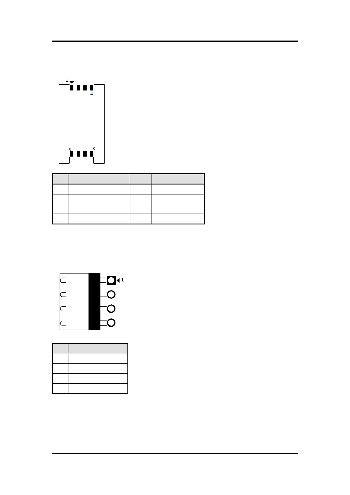
Pin
Description
1
X+ 2 X-
3
Y+
4
Sense
5
X+
6
X-
7
Y+ 8 Y-
9
GND
LVDS inverter connector: CN2
CN2 Pin Assignment
TOUCH connector: CN3
CN3 Pin Assignment
26 Hardware and Installation
Page 33
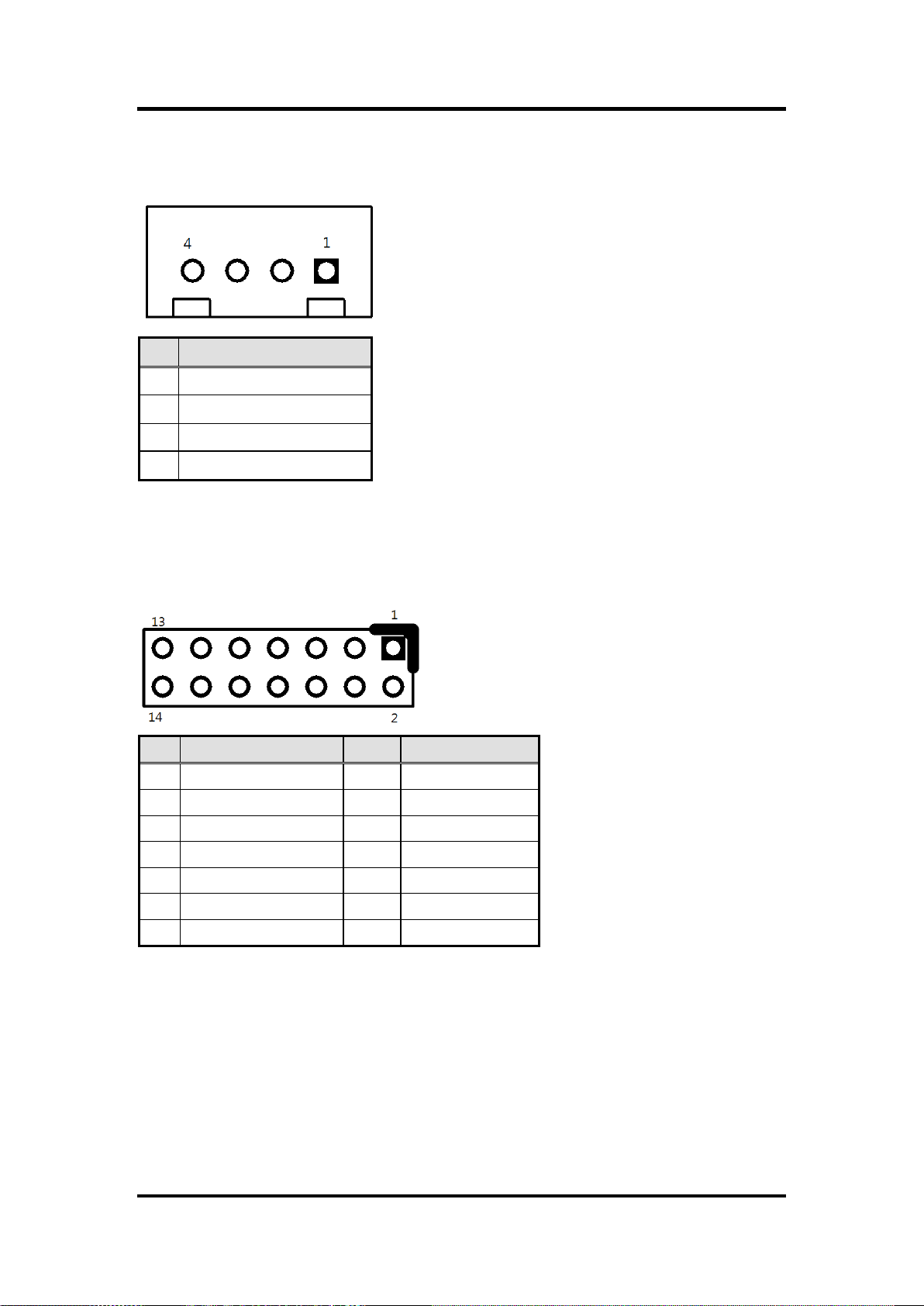
Pin
Description
1
+12V
2
GND
3
GND
4
+5V
Pin
Description
Pin
Description
1
+ 5V
2
Beep
3
GND
4
BUZZER
5
GND
6
Beep 7 NC
8
+5V 9 GND
10
PWBTN
11
GND
12
RESET
13
SATA LED
14
+3.3V
HDD power connector: CN4
CN9 Pin Assignment
FRONT PANEL pin header: CN6
CN6 Pin Assignment
FDK172-834 User’s Manual
Hardware and Installation 27
Page 34
FDK172-834 User’s Manual
Pin
Description
Pin
Description
1
UIM PWR
5
GND
2
UIM RST
6
UIM VPP
3
UIM CLK
7
UIM DATA
4
NC 8 NC
Pin
Description
1
DCIN (9V -36V)
2
DCIN (9V -36V)
3
GND
4
GND
SIM card connector: CN7
CN7 Pin Assignment
Power connector: CN9
CN9 Pin Assignment
28 Hardware and Installation
Page 35
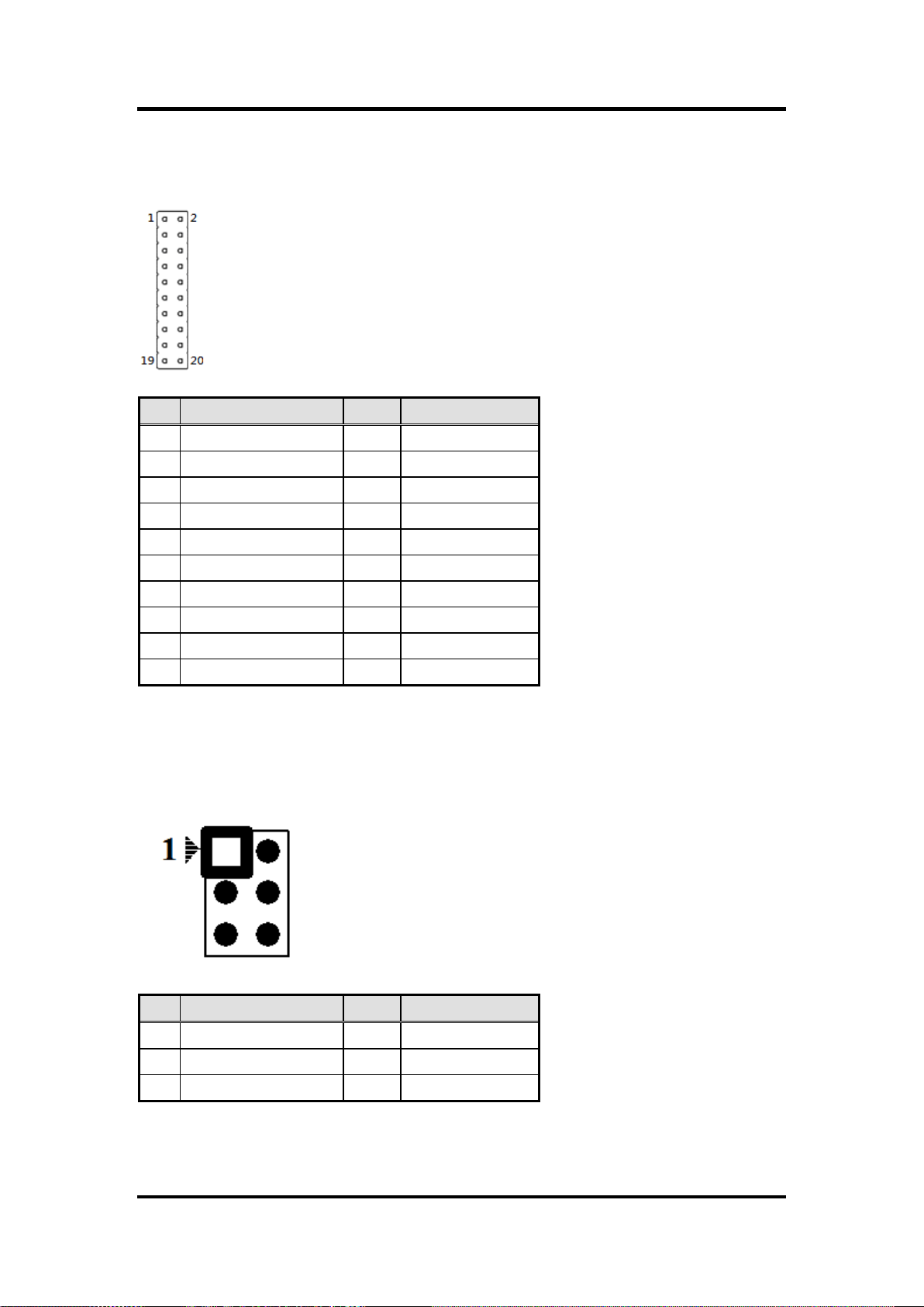
Pin
Description
Pin
Description
1
GND
6
GND
2
GPIO0
7
GPIO1
3
GPIO2
8
GPIO3
4
GPIO4
9
GPIO5
5
GPIO6
10
GPIO7
11
GPIO8
12
GPIO9
13
GPIO10
14
GPIO11
15
GPIO12
16
GPIO13
17
GPIO14
18
GPIO15
19
GND
20
GND
Pin
Description
Pin
Description
1
SPKOUT_L-
2
SPKOUT_L +
3
SPKOUT_R-
4
SPKOUT_R +
5
MIC IN
6
GND
Digital I/O pin header: CN10
CN10 Pin Assignment
FDK172-834 User’s Manual
Speaker Out & MIC IN connector: CN11
CN11 Pin Assignment
Hardware and Installation 29
Page 36

FDK172-834 User’s Manual
Pin
Description
1
VCC
2
D-
3
D+ 4 GND
5
GND
Pin
Signal
Pin
Signal
1
Red 2 GND
3
Green
4
N.C.
5
Blue
6
N.C.
7
VCC
8
DDC DATA
9
GND
10
N.C.
11
GND .
12
Horizontal Sync
13
GND
14
Vertical Sync
15
DCC CLK
16
N.C.
VGA Cable Connector: CN12
CN12 Pin Assignment
USB CONNECTOR (reserved): CN14/CN20
CN14/CN20 Pin Assignment
30 Hardware and Installation
Page 37
Pin
Description
1
LINE IN L
2
GND
5
LIN IN R
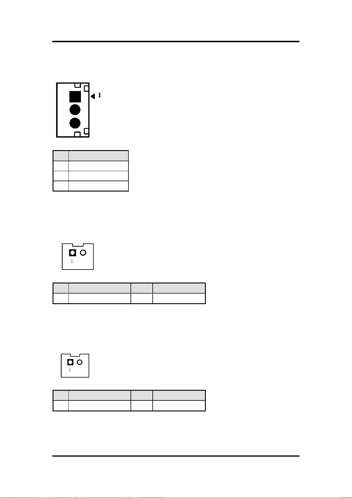
Pin
Description
Pin
Description
1
Power (+5V)
2
GND
Pin
Description
Pin
Description
1
Power Button
2
GND
Audio Lin In connector: CN15
CN15 Pin Assignment
Power lamp connector: CN16
CN16 Pin Assignment
FDK172-834 User’s Manual
Power button connector: CN17
CN17 Pin Assignment
Hardware and Installation 31
Page 38

FDK172-834 User’s Manual
Pin
Description
1
ON/OFF button
2
GND
3
LED
Pin
Description
1
GND
2
Panel ON/OFF
3
Abnormal indicate LED
4
Normal indicate LED
5
Blacklight down
6
Blacklight up
Touch function enable/disable & LED indicator connector: CN18
CN18 Pin Assignment
Panel control Keypad connector: CN19
CN19 Pin Assignment
32 Hardware and Installation
Page 39

Pin
Description
Pin
Description
1
+5V 2 +5V 3 USB-
4
USB-
5
USB+
6
USB+
7
GND
8
GND
9
GND
10
GND
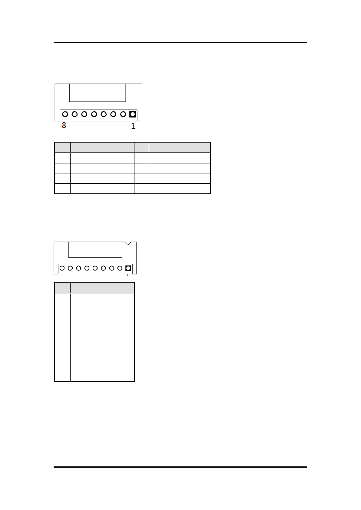
Pin
Description
Pin
Description
1
DCD
2
DSR
3
RX 4 RTS
5
TX 6 CTS
7
DTR
8
RI 9 GND
10
NC
USB box header: USB1
USB1 Pin Assignment
Serial Port box header: COM3, COM4
COM3, COM4 Pin Assignment
FDK172-834 User’s Manual
Hardware and Installation 33
Page 40

FDK172-834 User’s Manual
This page is intentionally left blank.
34 Hardware and Installation
Page 41

FDK172-834 User’s Manual
Left/Right
The Left and Right <Arrow> keys allow you to select a setup screen.
Up/Down
The Up and Down <Arrow> keys allow you to select a setup screen or sub-screen.
+ Plus/Minus
The Plus and Minus <Arrow> keys allow you to change the field value of a particular
setup item.
Tab
The <Tab> key allows you to select setup fields.
F1
The <F1> key allows you to display the General Help screen.
F2
The <F2> key allows you to load previous value
F3
The <F3> key allows you to Load Optimized Defaults.
F4
The <F4> key allows you to save any changes you have made and exit Setup.
Press the <F4> key to save your changes.
Esc
The <Esc> key allows you to discard any changes you have made and exit the
Setup. Press the
<Esc> key to exit the setup without saving your changes.
Enter
The <Enter> key allows you to display or change the setup option listed for a
particular setup item. The <Enter> key can also allow you to display the setup subscreens.
Chapter 3
AMI BIOS Setup Utility
This chapter provides users with detailed description how to set up basic system configuration
through the AMIBIOS8 BIOS setup utility.
3.1 Navigation Keys
The BIOS setup/utility uses a key-based navigation system called hot keys. Most of the BIOS
setup utility hot keys can be used at any time during the setup navigation process.
These keys include <F1>, <F2>, <F3>, <F4>, <Enter>, <ESC>, <Arrow> keys, and so on.
NOTE Some of navigation keys differ from one screen to another.
AMI BIOS Setup Utility 35
Page 42

FDK172-834 User’s Manual
3.2 Main Menu
System Time/Date
Use this option to change the system time and date. Highlight System Time or System Date
using the <Arrow> keys. Enter new values through the keyboard. Press the <Tab> key or the
<Arrow> keys to move between fields. The date must be entered in MM/DD/YY format. The
time is entered in HH:MM:SS format.
36 AMI BIOS Setup Utility
Page 43

3.3 Advanced Menu
FDK172-834 User’s Manual
The Advanced menu allows users to set configuration of the CPU and other system devices.
You can select any of the items in the left frame of the screen to go to the sub menus:
ACPI Settings
NCT6106D Super IO Configuration
NCT6106D H/W Monitor
CPU Configuration
IDE Configuration
Security Configuration
LPSS & SCC Configuration
For items marked with “”, please press <Enter> for more options.’
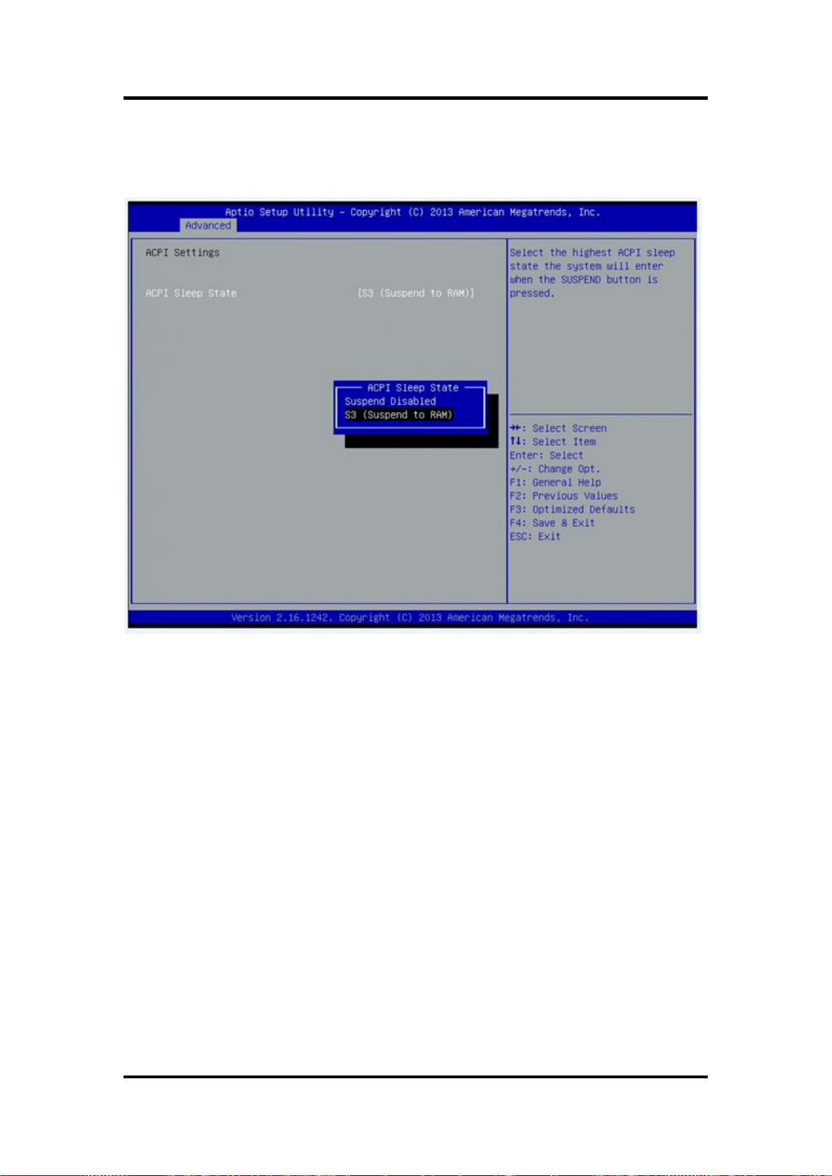
ACPI Settings
You can use this screen to select options for the ACPI Configuration, and change the value of
the selected option. A description of the selected item appears on the right side of the screen.
AMI BIOS Setup Utility 37
Page 44
FDK172-834 User’s Manual
ACPI Sleep State
Allow you to select the Advanced Configuration and Power Interface (ACPI) state to be used
for system suspend. Here are the options for your selection, Suspend disable and S3
(Suspend to RAM).
38 AMI BIOS Setup Utility
Page 45
FDK172-834 User’s Manual
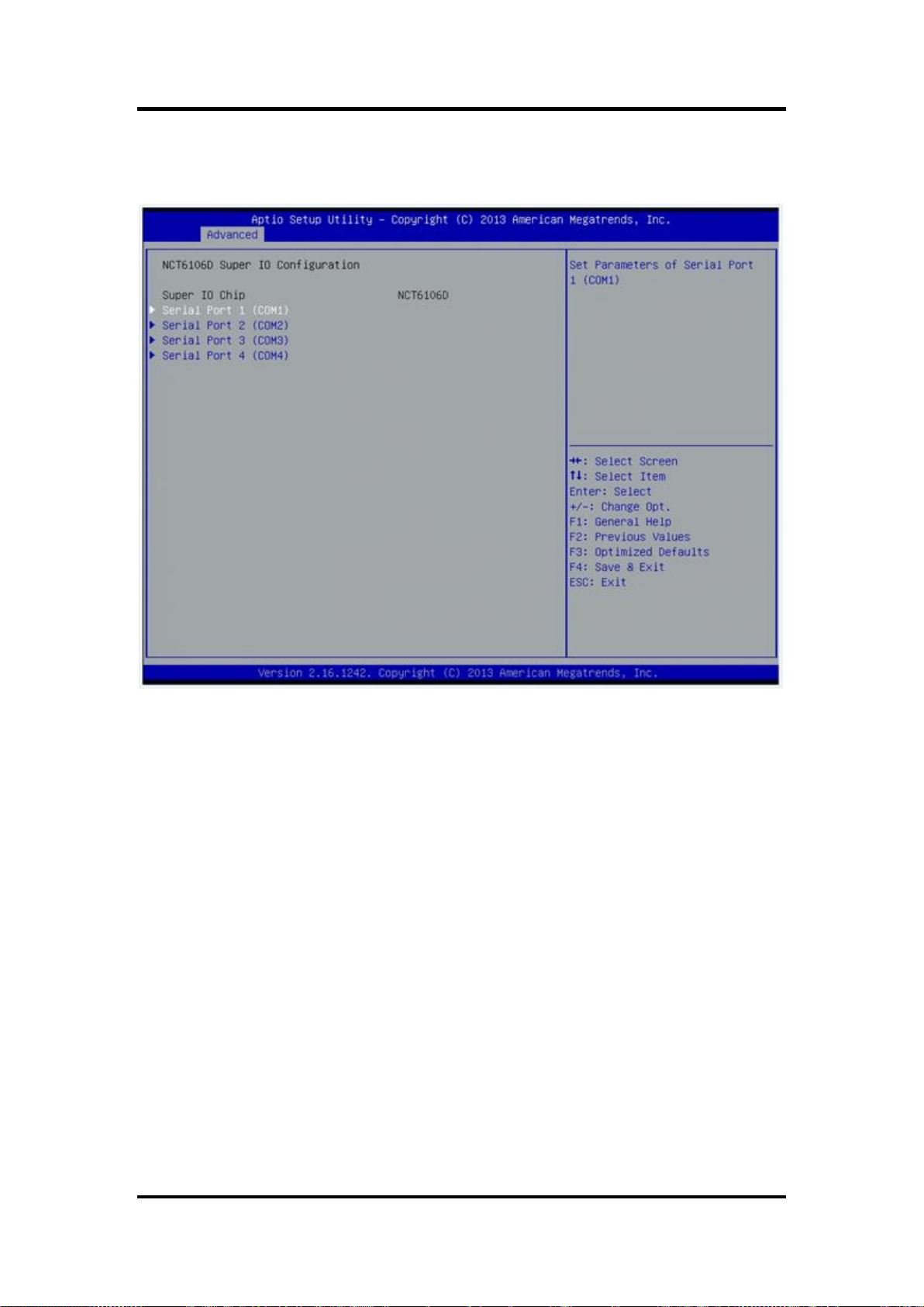
NCT6106D Super IO Configuration
Use this screen to select options for the Super IO Configuration, and change the value of the
selected option
Serial Port 1-4 configuration
Serial port:
This option used to enable or disable the serial port.
Device Setting:
This item specifies the base I/O port address and Interrupt Request address of serial port.
The port 0 Optimal setting is 3F8/IRQ4.
The port 1 Optimal setting is 2F8/IRQ3.
The port 2 Optimal setting is 3E8/IRQ7
The port 3 Optimal setting is 2E8/IRQ5.
AMI BIOS Setup Utility 39
Page 46

FDK172-834 User’s Manual
Serial type
This option used to select RS232/422/485 function.
40 AMI BIOS Setup Utility
Page 47

NCT6106D H/W Monitor
This screen shows the Hardware Health Configuration.
FDK172-834 User’s Manual
AMI BIOS Setup Utility 41
Page 48

FDK172-834 User’s Manual
CPU Configuration
This screen shows the CPU Configuration and Intel virtualization technology enable/disable
selected
42 AMI BIOS Setup Utility
Page 49

FDK172-834 User’s Manual
IDE Configuration
You can use this screen to select options for the SATA Configuration, and change the value of
the selected option.
SATA Mode
Use this item to choose the SATA operation mode. Here are the options for your selection, IDE
Mode, AHCI Mode.
AMI BIOS Setup Utility 43
Page 50
FDK172-834 User’s Manual
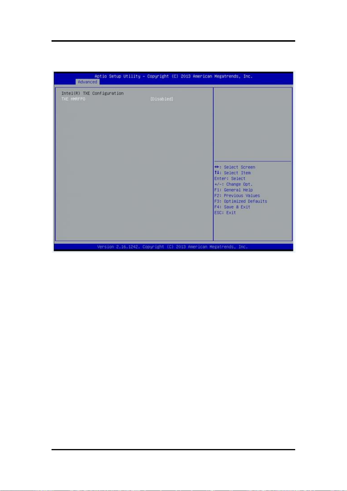
Security Configuration
The Advanced menu allows users to update the TXE firmware.
44 AMI BIOS Setup Utility
Page 51

FDK172-834 User’s Manual
LPSS & SCC Configuration
You can select any of the items in the frame of the screen to change the OS, the default setting
is Win 7.
Please be informed to select the Windows 8.x when installing Win 8 or Win 8.1.
If using the Android OS, please refer to https://01.org/android-ia.
AMI BIOS Setup Utility 45
Page 52
FDK172-834 User’s Manual
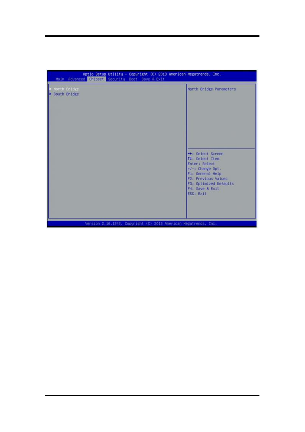
3.4 Chipset Menu
The Chipset menu allows users to change the advanced chipset settings.
46 AMI BIOS Setup Utility
Page 53

North Bridge
This screen shows the North Bridge memory information.
FDK172-834 User’s Manual
South Bridge
AMI BIOS Setup Utility 47
Page 54

FDK172-834 User’s Manual
USB Configuration
You can use this screen to select options for the USB Configuration,
If USB3.0 function used, XHCI Mode must enable and EHCI must disable.
**XHCI default is Auto.
48 AMI BIOS Setup Utility
Page 55

3.5 Security
FDK172-834 User’s Manual
AMI BIOS Setup Utility 49
Page 56
FDK172-834 User’s Manual
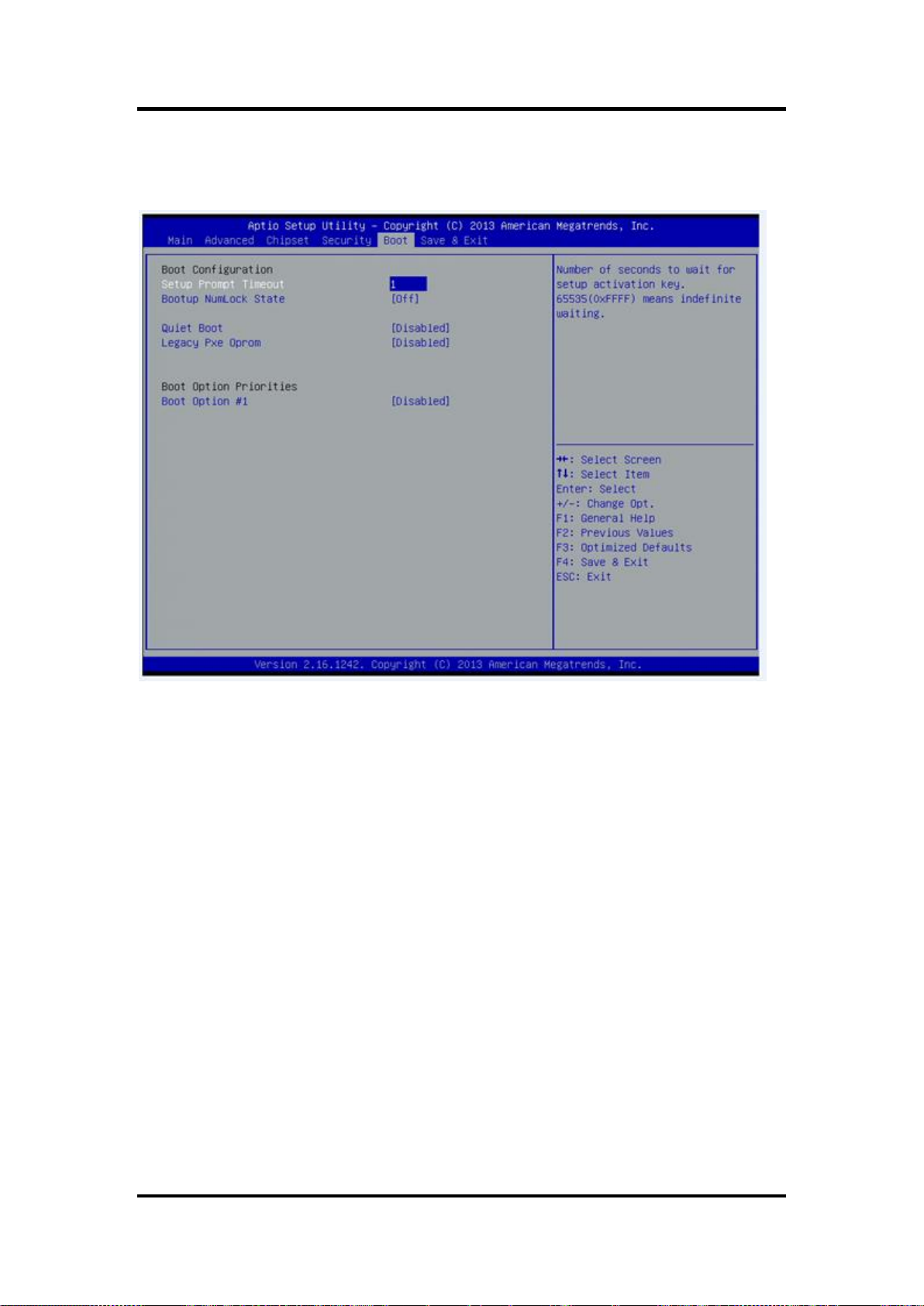
3.6 Boot Menu
The Boot menu allows users to change boot options of the system. You can select any of the
items in the left frame of the screen to go to the sub menus:
Setup Prompt Timeout
Set the Timeout for wait press key to enter Setup Menu.
Bootup NumLock State
Use this item to select the power-on state for the NumLock. The default setting is on.
Quiet Boot
Use this item to enable or disable the Quite Boot state. The default setting is disable.
Legacy Pxe OPROM
Use this item to enable or disable the reboot Execution Environment. The default setting is
disable.
Boot Option Priorities
Specifies the overall boot order from the available devices.
50 AMI BIOS Setup Utility
Page 57
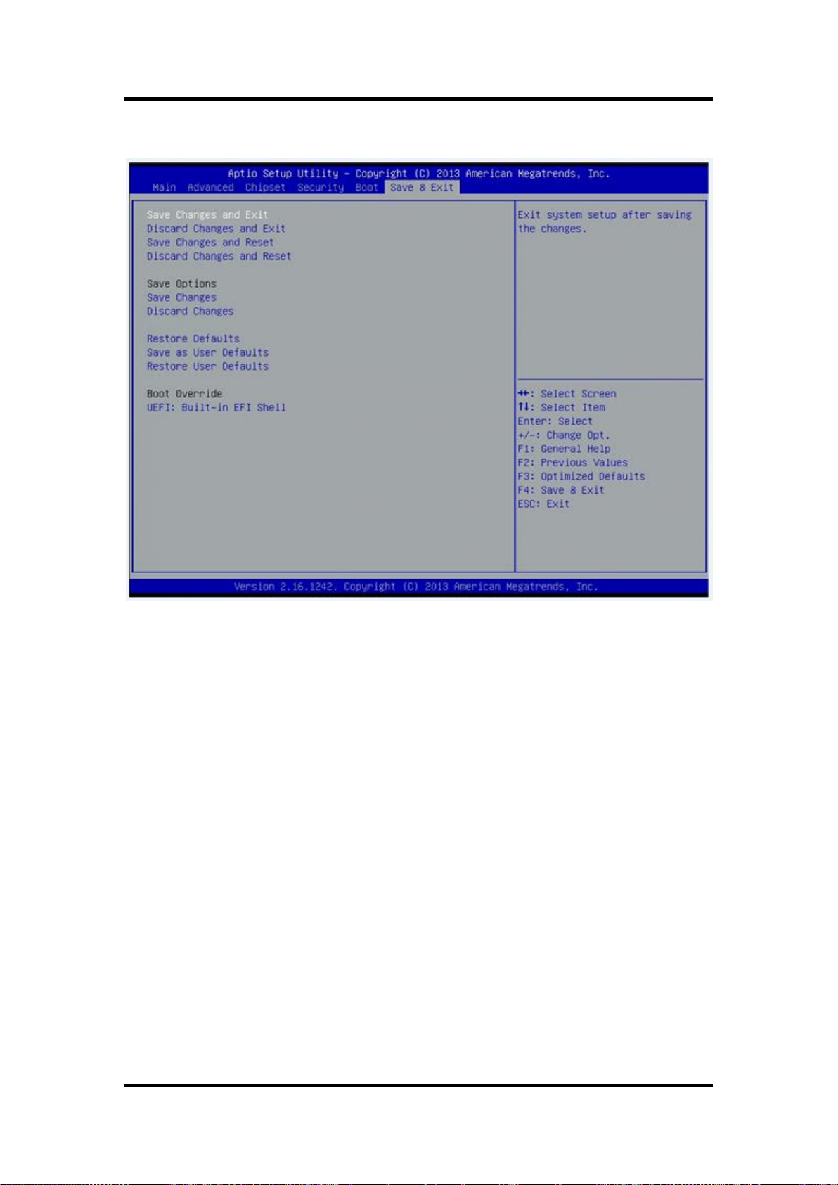
3.7 Save&Exit
FDK172-834 User’s Manual
AMI BIOS Setup Utility 51
Page 58

FDK172-834 User’s Manual
This page is intentionally left blank.
52 AMI BIOS Setup Utility
Page 59

FDK172-834 User’s Manual
Chapter 4
Drivers Installation
4.1 System
GOT5152T-834 supports Windows 7, Windows 8/8.1 ,WES 7 and WE8S. To facilitate the
installation of system driver, please carefully read the instructions in this chapter before start
installing.
4.1.1 Win 7
1. Insert Driver CD and select the “\Drivers”.
2. Select all files and follow the installing procedure.
NOTE Please install Microsoft KB2685811 before TXE installation under Windows 7,
then installing the drivers.
NOTE If graphic driver isn’t installed under Win7 or Win 8.x, only VGA function can
be waked up when VGA and DP in hibernate mode. In order to solve this issue,
user needs to re-start the computer or ensure the graphic driver is installed
properly.
Drivers Installation 53
Page 60
FDK172-834 User’s Manual
Touch Screen
5-wire Analog Resistive type
Touch Screen Controller
PenMount 6000 USB Touch Screen Controller IC
Communications
USB interface
Resolution
1024 x 1024
Power Input
5V
Power Consumption
Active: 24.6mA / Idle Mode: 13.4mA
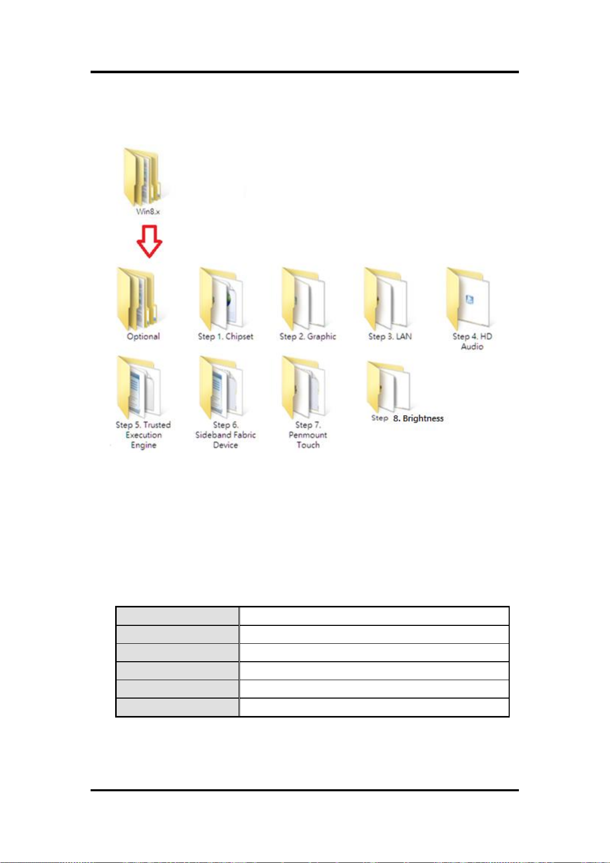
4.1.2 Win 8/8.x
1. Insert Driver CD and select the “\Drivers”.
2. Select all files and follow the installing procedure.
4.2 Touch Screen
The GOT5152T-834 uses the 5-wire analog resistive. There are the specification and driver
installation which are listed below.
4.2.1 Specification
54 Drivers Installation
Page 61
FDK172-834 User’s Manual
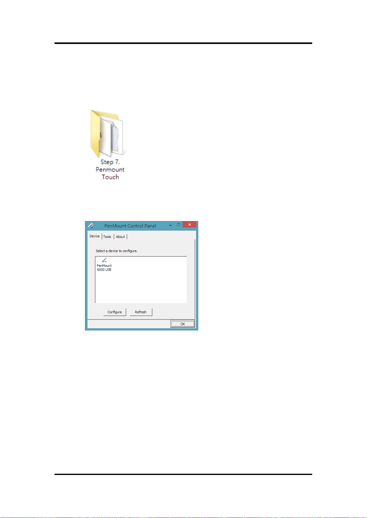
4.2.2 Driver Installation- Windows 7/8.x
The GOT5152T-834 provides a touch screen driver that users can install it under the
operating system Windows 7/8.x. To facilitate installation of the touch screen driver, you
should read the instructions in this chapter carefully before you attempt installation.
1. Insert Driver CD and follow the path to select the “\Drivers\Step 7 - Touch”.
2. Follow the installing procedure and press OK.
3. Click Start menu and select “PenMount Utilities”; and then, a “PenMount Control
Panel” pops out.
Drivers Installation 55
Page 62

FDK172-834 User’s Manual
4. Select the “Standard Calibrate” tab.
5. Calibration:
To adjust the display with touch panel, click “Calibration” and follow the calibrate
point to do calibration; there are five points on screen for calibration.
6. Press OK.
56 Drivers Installation
Page 63

FDK172-834 User’s Manual
4.3 Embedded O.S.
The GOT5152T-834 provides the WES 7 and WE8S Embedded. The O.S. is supported
devices which are listed below.
4.3.1 WES 7 & WE8S
Here are supported onboard devices:
Onboard Multi I/O
SATA HDD
USB
CRT/LCD display
10/100/1000 base-T Ethernet
CFast
Onboard Audio
Touch Screen
PenMount Touch screen
Before you can use and calibrate it, here is what you should do:
1. Set up Penmount touch device driver by executing C:\Penmount\ Windows
2. Calibrate Penmount touch by clicking on the “PM” icon, and the go on the
3. Restart the computer.
TM
or mSATA
2000-XP V5.0\setup.exe. When the installation is finished, an icon “PM” appears on
the Taskbar.
calibration.
Drivers Installation 57
Page 64

FDK172-834 User’s Manual
This page is intentionally left blank.
58 Drivers Installation
Page 65

FDK172-834 User’s Manual
Begin
Enable and Initialize
Watchdog Timer
Program “A”
Disable Watchdog
Timer
Next
Next
Next
Next
Begin
Enable and Initialize
Watchdog Timer
Program “A”
Reset Watchdog
Timer
Next
Next
Next
Next
Appendix A
Watchdog Timer
About Watchdog Timer
Software stability is major issue in most application. Some embedded systems are not
watched by human for 24 hours. It is usually too slow to wait for someone to reboot when
computer hangs. The systems need to be able to reset automatically when things go wrong.
The watchdog timer gives us solution.
The watchdog timer is a counter that triggers a system reset when it counts down to zero from
a preset value. The software starts counter with an initial value and must reset it periodically. If
the counter ever reaches zero which means the software has crashed, the system will reboot.
How to Use Watchdog Timer
The I/O port base addresses of watchdog timer are 2E (hex) and 2F (hex). The 2E (hex) and
2F (hex) are address and data port respectively.
Assume that program A is put in a loop that must execute at least once every 10ms. Initialize
watchdog timer with a value bigger than 10ms. If the software has no problems; watchdog
timer will never expire because software will always restart the counter before it reaches zero.
Watchdog Timer 59
Page 66

FDK172-834 User’s Manual
WDT Sample Program
Enable WDT
1.Enable configuration
-O 2E 87
-O 2E 87
2. Select Logic device:
-O 2E 07
-O 2F 08
3. WDT Device Enable
-O 2E 30
-O 2F 01
4. Set timer unit
-O 2E F0
-O 2F 00 (00: Sec; 08: Minute)
5. Set base timer:
-O 2E F1
-O 2F 0A Set Reset Time (Ex.0A:10 Sec)
Disable WDT
1.Enable configuration
-O 2E 87
-O 2E 87
2. Select Logic device:
-O 2E 07
-O 2F 08
3. WDT Device Disable
-O 2E 30
-O 2F 00
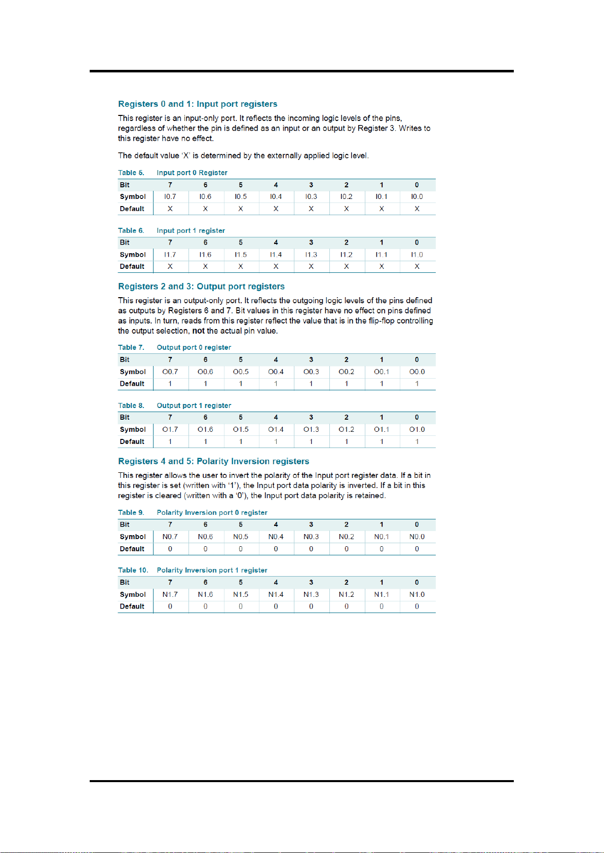
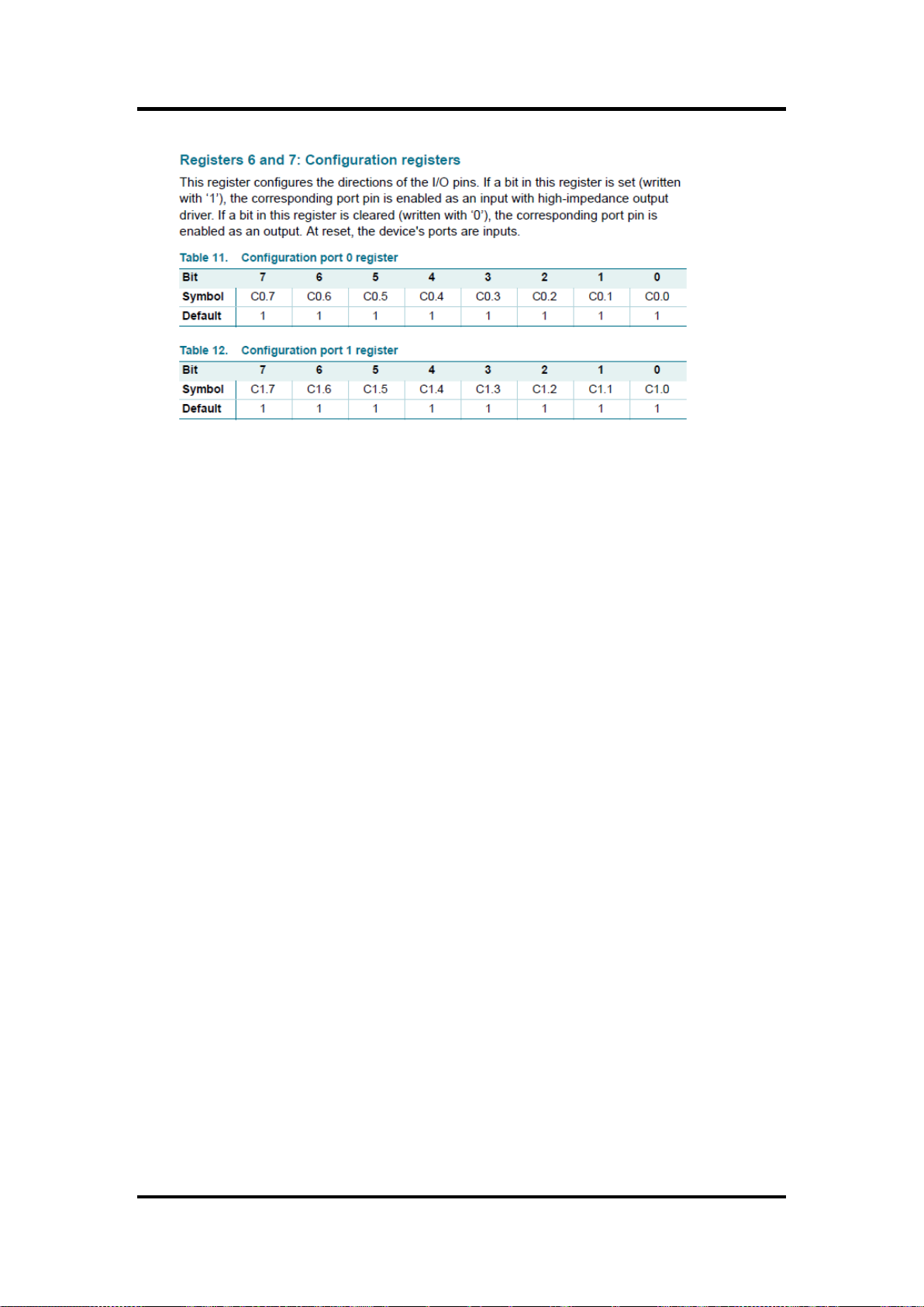
Digital I/O Software Programming
I2C to GPIO PCA9535PW GPIO
I2C address: 0b01000000.
60 Watchdog Timer
Page 67
FDK172-834 User’s Manual
Watchdog Timer 61
Page 68
FDK172-834 User’s Manual
62 Watchdog Timer
Page 69
FDK172-834 User’s Manual
Appendix B
Backlight Control
About Backlight Control
Axiomtek offers the backlight control tool under Windows 7 and Windows 8, people can adjust
the panel backlight depending on your personal taste and the amount of ambient light in the
room after installing the backlight control tool.
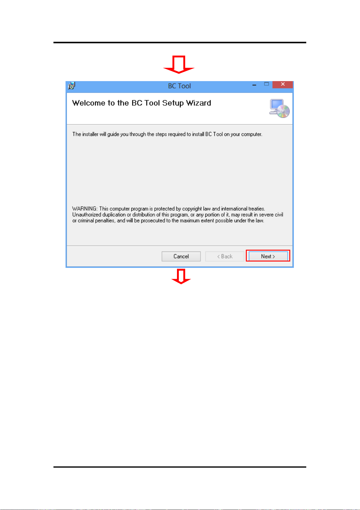
How to Use Backlight Control
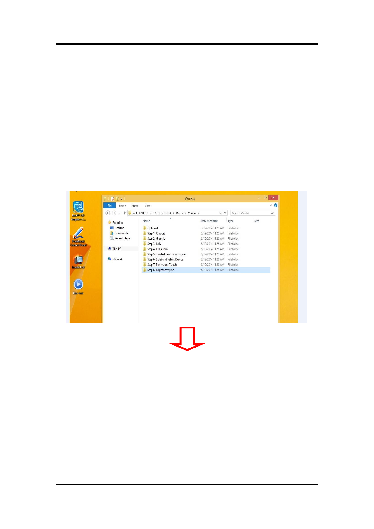
Step 1 According to the OS version, please insert the driver CD and follow the
path to select the proper driver, “\Driver\Win8.x\Step 8 – BrightnessSync” or
\Driver\Win7\Step 8 - BrightnessSync”.
Backlight Control 63
Page 70

FDK172-834 User’s Manual
64 Backlight Control
Page 71
FDK172-834 User’s Manual
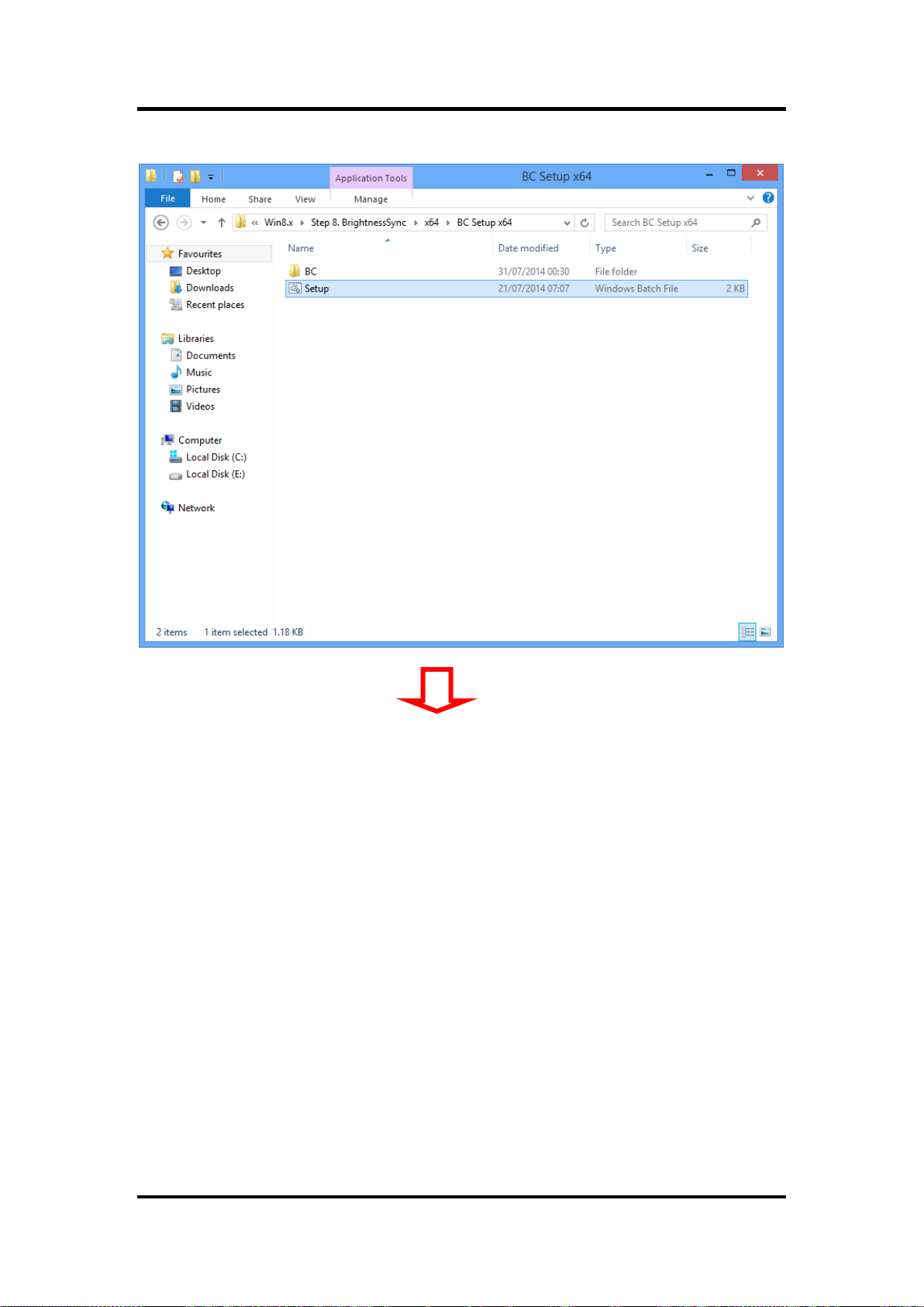
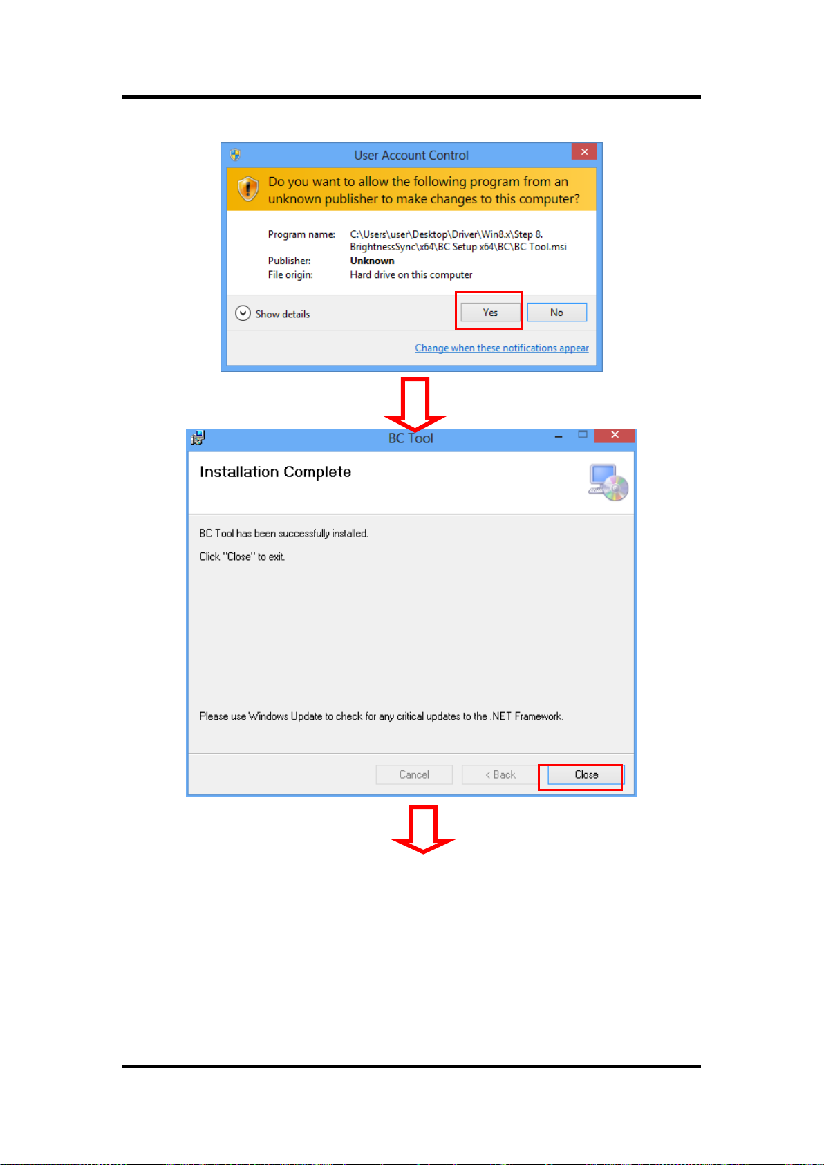
Step 2 Follow the installing procedures and press “Close”.
Backlight Control 65
Page 72

FDK172-834 User’s Manual
66 Backlight Control
Page 73
FDK172-834 User’s Manual
Backlight Control 67
Page 74

FDK172-834 User’s Manual
68 Backlight Control
Page 75
FDK172-834 User’s Manual
Backlight Control 69
Page 76
FDK172-834 User’s Manual
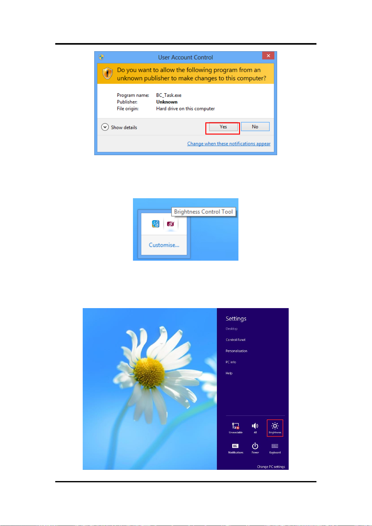
Step 3 System auto reboot, installation completed.
Step 4 Select “△” icon then find out the “Axiomtek” to ensure the brightness driver
is installed appropriately.
Step 5 How to use the brightness Control
There are two ways to adjust the display brightness.
Step 5.1 Click the “Brightness” to adjust the display brightness with the bar.
(For Windows 8.x only.)
70 Backlight Control
Page 77

FDK172-834 User’s Manual
Step 5.2. Click the “Control Panel” then select “Power Options” to adjust the display
brightness.
Backlight Control 71
Page 78

FDK172-834 User’s Manual
Removed Brightness Control Tool
Step 1 According to the OS version, please insert the driver CD and follow the
path to select the proper driver, “\Driver\Win8.x\Step 8 – Setup” or
\Driver\Win7\Step 8 - Setup”.
72 Backlight Control
Page 79

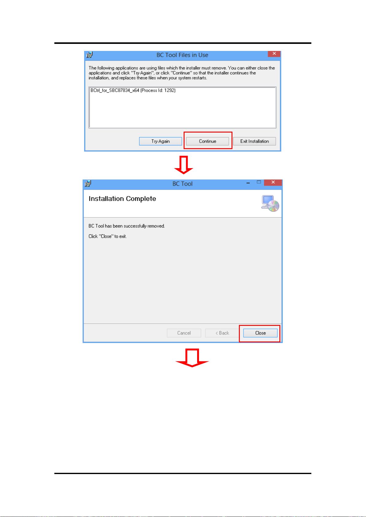
Step 2 Follow the procedures and press “Close”.
FDK172-834 User’s Manual
Backlight Control 73
Page 80
FDK172-834 User’s Manual
74 Backlight Control
Page 81

FDK172-834 User’s Manual
Step 3 System auto reboot, uninstallation completed.
Backlight Control 75
Page 82

FDK172-834 User’s Manual
This page is intentionally left blank.
76 Backlight Control
 Loading...