

Page 1

ETM831 Series
Intel
®
Atom
ETX v3.01 SoM
With
Multiple I/O Features
User’s Manual
Page 2

ii
Disclaimers
This manual has been carefully checked and believed to contain
accurate information. AXIOMTEK Co., Ltd. assumes no responsibility
for any infringements of patents or any third party’s rights, and any
liability arising from such use.
AXIOMTEK does not warrant or assume any legal liability or
responsibility for the accuracy, completeness or usefulness of any
information in this document. AXIOMTEK does not make any
commitment to update the information in this manual.
AXIOMTEK reserves the right to change or revise this document
and/or product at any time without notice.
No part of this document may be reproduced, stored in a retrieval
system, or transmitted, in any form or by any means, electronic,
mechanical, photocopying, recording, or othe rw ise, witho ut the pri or
written permission of AXIOMTEK Co., Ltd.
CAUTION
If you replace wrong batteries, it causes the danger of explosion. It is
recommended by the manufacturer that you follow the manufacturer’s
instructions to only replace the same or equivalent type of battery,
and dispose of used ones.
©Copyright 2009 AXIOMTEK Co., Ltd.
All Rights Reserved
November 2009, Version A1
Printed in Taiwan
Page 3

iii
ESD Precautions
Computer boards have integrated circuits sensitive to static electricity.
To prevent chipsets from electrostatic discharge damage, please take
care of the following jobs with precautions:
Do not remove boards or integrated circuits from their anti-static
packaging until you are ready to install them.
Before holding the board or integrated circuit, touch an unpainted
portion of the system unit chassis for a few seconds. It
discharges static electricity from your body.
Wear a wrist-grounding strap, available from most electronic
component stores, when handling boards and components.
Trademarks Acknowledgments
AXIOMTEK is a trademark of AXIOMTEK Co., Ltd.
Windows
®
is a trademark of Microsoft Corporation.
AMI are trademarks of American Megatrend Inc.
IBM, PC/AT, PS/2, VGA are trademarks of International Business
Machines Corporation.
Intel
®
and Atom are trademarks of Intel Corporation.
Winbond is a trademark of Winbond Electronics Corp.
Realtek is a trademark of Realtek Semi-Conductor Co., Ltd.
Other brand names and trademarks are the properties and registered
brands of their respective owners.
Page 4

iv
Table of Contents
Disclaimers....................................................................................ii
ESD Precautions.......................................................... ................iii
C h a p t e r 1.................................................................................... 1
Introduction............................................................................ ............1
1.1 Specifications..............................................................2
1.2 Utilities Supported.......................................................4
C h a p t e r 2.................................................................................... 5
Board Layout and Connectors...........................................................5
2.1 Board Layout and Fixing Holes...................................5
2.2 Board Dimensions ...................................................... 7
2.3 Heatspreader Installation........................................... .9
2.4 Connectors & Jumper Settings.................................11
2.4.1 ETX Connector – X1: CNS3.....................................12
2.4.2 ETX Connector – X2: CNS1.....................................14
2.4.3 ETX Connector – X3: CNS4.....................................16
2.4.4 ETX Connector – X4: CNS2.....................................18
2.4.5 7-pin SATA Connectors: SATA1, SATA2................. 20
2.4.6 Audio Connector: SFC1(Optional)............................20
2.4.7 Auto Power On Jumper: JP1.....................................21
CHAPTER 3.....................................................................................22
HARDWARE DESCRIPTION..........................................................22
3.1 Microprocessors .......................................................22
3.2 BIOS..........................................................................22
3.3 System Memory........................................................22
3.4 I/O Port Address MAP ..............................................22
3.5 Interrupt Controller....................................................25
CHAPTER 4.....................................................................................26
AMI BIOS SETUP UTILITY .............................................................26
4.1 Starting......................................................................26
4.2 Navigation Keys........................................................26
4.3 Main Menu................................................................27
4.4 Advanced Menu........................................................28
4.5 PCI PnP Menu..........................................................44
4.6 Boot Menu................................................................. 45
4.7 Security Menu...........................................................48
Page 5

v
4.8 Chipset Menu............................................................49
4.9 Exit Menu..................................................................53
A p p e n d i x A ...............................................................................55
Watchdog Timer .............................................................................. 55
Using the Watchdog Function....................................................56
Page 6

Page 7
ETM831 All-In-One ETX v3.01 SoM User’s Manual
Introduction
1
C h a p t e r 1
Introduction
The ETM831 Series is a finest embedded ETX system-on-a-module
in the market, which makes a generic interface to connect the module
to peripherals such as hard disk, mouse, and display. It supports
Intel
®
Atom N270 processor with 533MHz FSB (Front Side Bus).
The board integrates Intel
®
945GSE and ICH7M chipsets that support
one 200-pin DDR2-400/533 SDRAM with maximum up to 2GB system
memory capacity. It makes the all-in-one single module together with
excellent Multiple I/O, dual independent display CRT and LVDS LCD
through ETX connector, Fast Ethernet and 5.1 Channel HD Codec
Audio. Through ETX connectors, it also provide one FDD/LPT port,
four PCI and one full ISA bus for expansion purpose, one PATA, two
SATA and four USB 2.0 ports for high speed peripherals. It can
achieve the best stability and reliability that makes your system
perform the most endurable operation in any critical environments.
The built-in Watchdog Timer has enhanced the system reliability that
achieves a unique feature to distinguish itself from other boards.
Page 8

ETM831 All-In-One ETX v3.01 SoM User’s Manual
Introduction
2
1.1 Specifications
z CPU: Intel
®
Atom N270 1.6GHz/512KB L2 cache processor
z CPU Frequency: FSB533MHz
z System Chipset: Intel
®
945GSE and ICH7M
z BIOS
AMI BIOS, Y2K compliant
8Mbit SPI Flash, DMI, Plug and Play
RPL/PXE Ethernet Boot ROM
SmartView for multiple LCD type selection, display
mode option and application extension features
“Load Optimized Default” customized Setting in the BIOS
flash chip to prevent from CMOS battery fail
z System Memory
One x 200-pin DDR2-400/533 SODIMM socket
Maximum to 2GB DDR2 memory
z L2 Cache: integrated in CPU
z Onboard IDE
One PATA port supported through ETX connector
Two SATA-150 connectors
z Onboard Multi-I/O
Two UARTs through ETX connector
z USB Interface
Four USB ports with fuse protection and complies with
USB Spec. Rev. 2.0
z Watchdog Timer
1~255 seconds; up to 255 levels
z Graphics
CRT: up to 2048 x 1536
LCD: 18/24-bit signal&dual channel LVDS up to 1600x1200
or 1920 x 1200 ( With Chrontel CH7308B populated )
Page 9

ETM831 All-In-One ETX v3.01 SoM User’s Manual
Introduction
3
z Expansion Interface
Four PCI Bus Masters supported
One Full ISA supported
z Ethernet
One RTL8103EL Fast Ethernet controller
z Audio
5.1 channel HD Codec Audio (optional)
Realtek ALC662, HD audio
MIC-in, Line-in, Line-out
z Power Management
ACPI (Advanced Configuration and Power Interface)
z Form Factor
ETX form factor 95 mm x114 mm
NOTE: All specifications and images are subject to change
without notice.
Page 10

ETM831 All-In-One ETX v3.01 SoM User’s Manual
Introduction
4
1.2 Utilities Supported
z Chipset Driver
z VGA Driver
z Ethernet Driver
z Audio Driver
Page 11
ETM831 All-In-One ETX v3.01 SoM User’s Manual
Hardware Description
5
C h a p t e r 2
Board Layout and Connectors
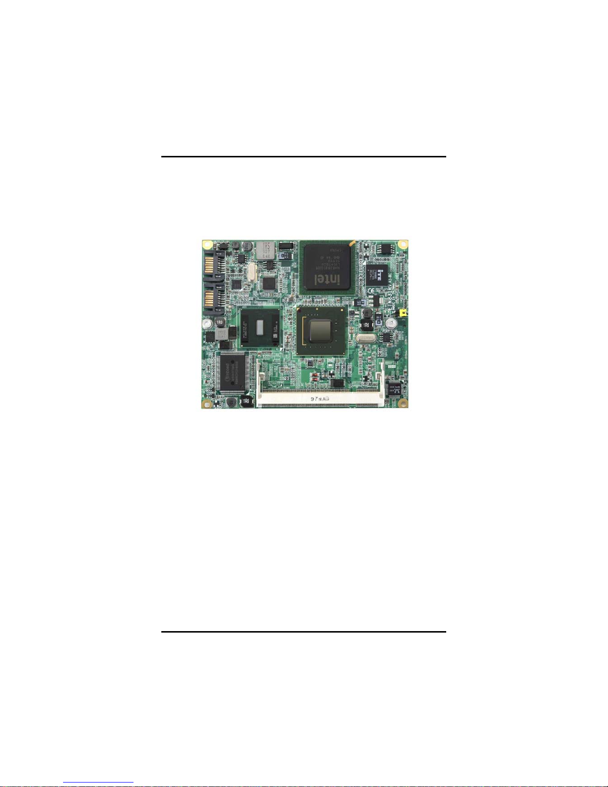
2.1 Board Layout and Fixing Holes
Component Side
Page 12
ETM831 All-In-One ETX v3.01 SoM User’s Manual
Hardware Description
6
Solder Side
Page 13
ETM831 All-In-One ETX v3.01 SoM User’s Manual
Hardware Description
7
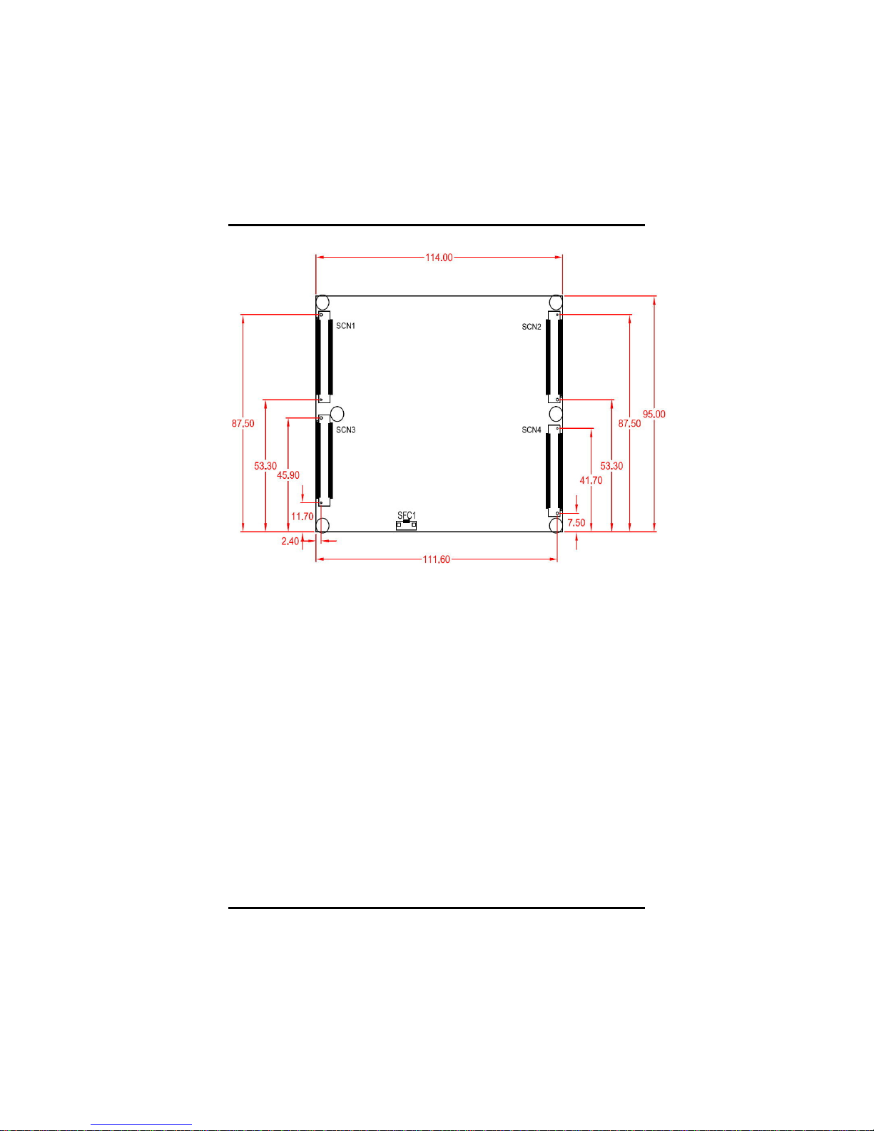
2.2 Board Dimensions
Component Side
Page 14
ETM831 All-In-One ETX v3.01 SoM User’s Manual
Hardware Description
8
Solder Side
Page 15
ETM831 All-In-One ETX v3.01 SoM User’s Manual
Hardware Description
9
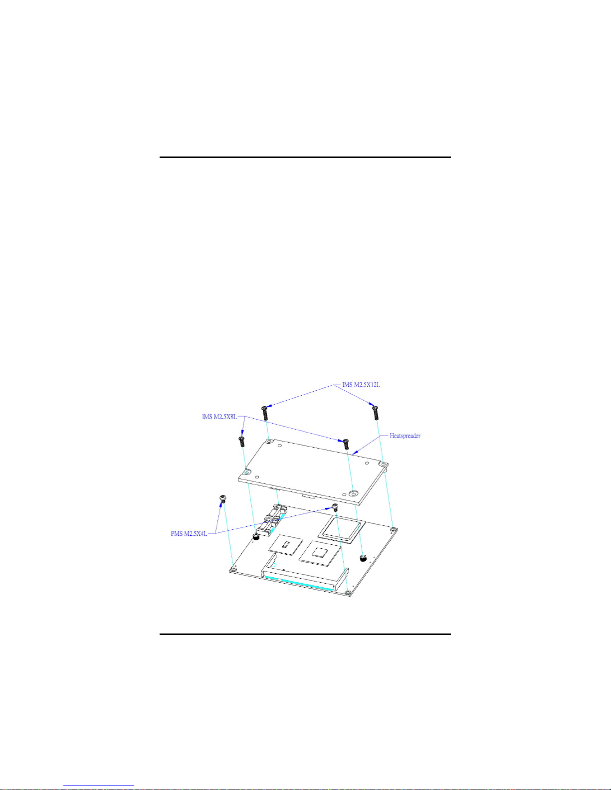
2.3 Heatspreader Installation
1. There is a protective plastic covering on the thermal pads. This
must be removed before the heatspreader can be mounted.
Each heatspreader is designed for a specific ETM module. The
thermal pads on the heatspreader are designed to make contact
with the necessary components on the ETM module. When
mounting the heatspreader you must make sure that the thermal
pads on the heatspreader make complete contact (no space
between thermal pad and component) with the corresponding
components on the ETM module. This is especially critical for
ETM modules that have higher CPU speeds (for example
1.0GHz or more) to ensure that the heatspreader acts as a
proper thermal interface for cooling solutions.
2. The two M2.5x8 screws and two M2.5x12 screws are used to
mount the heatspreader and ETM module assembly to the
baseboard. (see Figure 1)
3. If you have an additional thermal solution on the heatspreader,
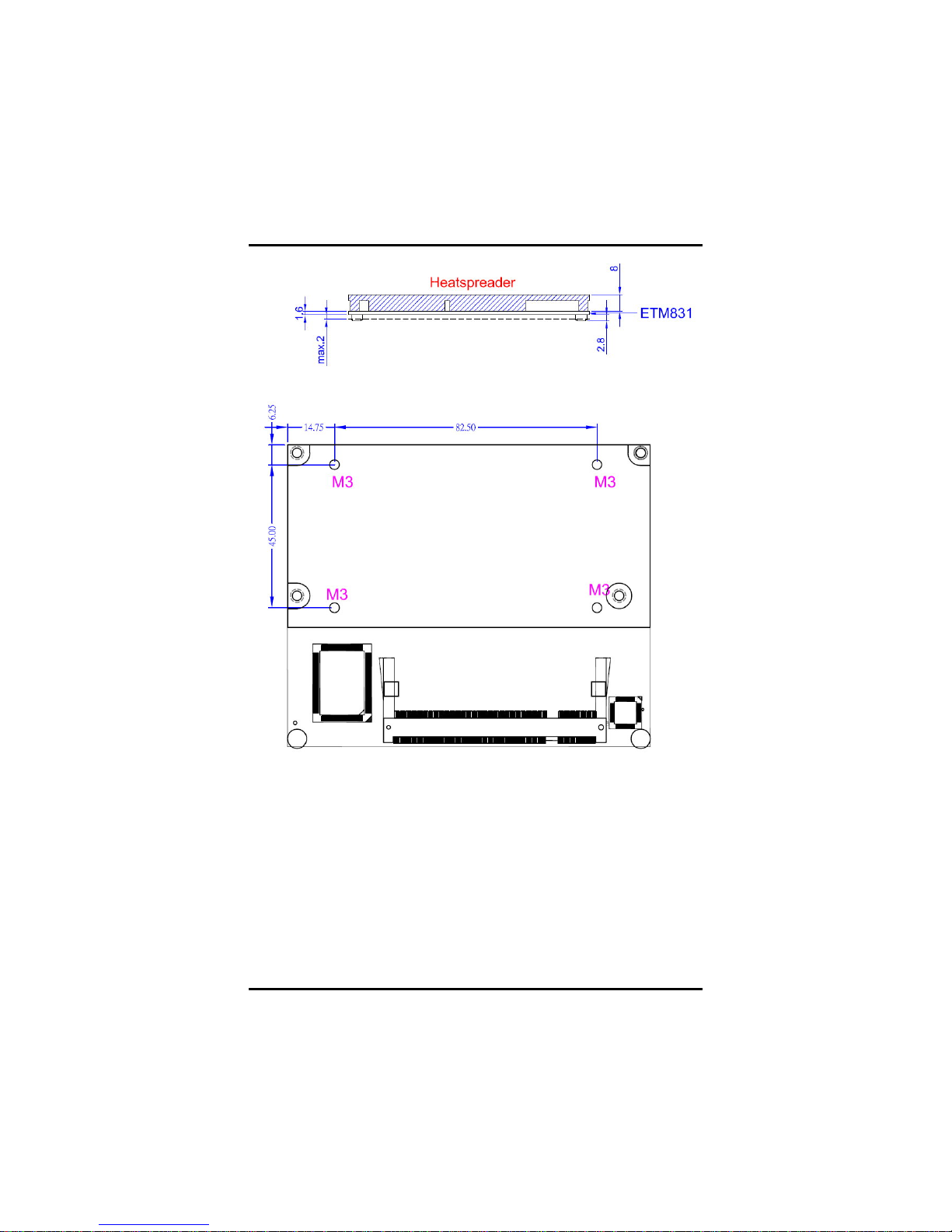
please refer to the ETM831 thermal solu tion design guide (see
Figure 2) to design your thermal solution.
Figure 1: ETM831 Heatspreader Assembly Guide
Page 16
ETM831 All-In-One ETX v3.01 SoM User’s Manual
Hardware Description
10
Figure 2: ETM831 Thermal Solution Design Guide
Page 17

ETM831 All-In-One ETX v3.01 SoM User’s Manual
Hardware Description
11
2.4 Connectors & Jumper Settings
Connectors connect the CPU card with other parts of the system.
Loose or improper connection might cause problems. Make sure all
connectors are properly and firmly connected. Here is a summary table
shows you all connectors on the ETM831 Series.
Connectors Label
SATA Connector SATA1
SATA Connector SATA2
DDRⅡSO-DIMM
DIMM1
Auro Power Button JP1
ETX Connector – X1 SCN3
ETX Connector – X2 SCN1
ETX Connector – X3 SCN4
ETX Connector – X4 SCN2
Audio Connector
(CH5.1: Rear-R/L,Center,LFE)
SFC1
Proper jumer settings configure the ETM831 to meet your application
purpose. We are herewith listing a summary table of all jumpers and
default settings for onboard devices, respectively.
Jumper Default Setting Jumper Setting
JP1 Auto Power ON
Default: Disable
Short
Page 18

ETM831 All-In-One ETX v3.01 SoM User’s Manual
Hardware Description
12
2.4.1 ETX Connector – X1: SCN3
Pin Description Pin Description
1 GND 2 GND
3 PCICLK3 4 PCICLK4
5 GND 6 GND
7 PCICLK1 8 PCICLK2
9 PCI_REQ3# 10 PCI_GNT3#
11 PCI_GNT2# 12 VCC3
13 PCI_REQ2# 14 PCI_GNT1#
15 PCI_REQ1# 16 VCC3
17 PCI_GNT0# 18 CPUFAN_IN
19 VCC 20 VCC
21 SERIRQ 22 PCI_REQ0#
23 PCI_AD0 24 VCC3
25 PCI_AD1 26 PCI_AD2
27 PCI_AD4 28 PCI_AD3
29 PCI_AD6 30 PCI_AD5
31 PCI_C/BE0# 32 PCI_AD7
33 PCI_AD8 34 PCI_AD9
35 GND 36 GND
37 PCI_AD10 38 LINE_IN_L
39 PCI_AD11 40 MIC_IN
41 PCI_AD12 42 LINE_IN_R
43 PCI_AD13 44 ASVCC
45 PCI_AD14 46 LINE_OUT_L
47 PCI_AD15 48 ASGND
49 PCI_C/BE1# 50 LINE_OUT_R
51 VCC 52 VCC
53 PCI_PAR 54 PCI_SERR#
Page 19

ETM831 All-In-One ETX v3.01 SoM User’s Manual
Hardware Description
13
Pin Description Pin Description
55 PCI_PERR# 56 CPUFAN_OUT
57 PCI_PME# 58 USB259 PCI_LOCK# 60 PCI_DEVSEL#
61 PCI_TRDY# 62 USB363 PCI_IRDY# 64 PCI_STOP#
65 PCI_FRAME# 66 USB2+
67 GND 68 GND
69 PCI_AD16 70 PCI_C/BE2#
71 PCI_AD17 72 USB3+
73 PCI_AD19 74 PCI_AD18
75 PCI_AD20 76 USB077 PCI_AD22 78 PCI_AD21
79 PCI_AD23 80 USB181 PCI_AD24 82 PCI_C/BE3#
83 VCC 84 VCC
85 PCI_AD25 86 PCI_AD26
87 PCI_AD28 88 USB0+
89 PCI_AD27 90 PCI_AD29
91 PCI_AD30 92 USB1+
93 PCI_RST# 94 PCI_AD31
95 PCI_INTC# 96 PCI_INTD#
97 PCI_INTA# 98 PCI_INTB#
99 GND 100 GND
-- End of ETX Connector-X1 (SCN3) Pin Assignment Table --
Page 20

ETM831 All-In-One ETX v3.01 SoM User’s Manual
Hardware Description
14
2.4.2 ETX Connector – X2: SCN1
Pin Description Pin Description
1 GND 2 GND
3 ISA_SD14 4 ISA_SD15
5 ISA_SD13 6 MASTER#
7 ISA_SD12 8 DREQ7
9 ISA_SD11 10 DACK7#
11 ISA_SD10 12 DREQ6
13 ISA_SD9 14 DACK6#
15 ISA_SD8 16 DREQ5
17 ISA_MEMW# 18 DACK5#
19 ISA_MEMR# 20 DREQ0
21 ISA_LA17 22 DACK0#
23 ISA_LA18 24 IRQ14
25 ISA_LA19 26 IRQ15
27 ISA_LA20 28 IRQ12
29 ISA_LA21 30 IRQ11
31 ISA_LA22 32 IRQ10
33 ISA_LA23 34 IOCS16#
35 GND 36 GND
37 SBHE# 38 MEMCS16#
39 ISA_SA0 40 ISA_OSC
41 ISA_SA1 42 BALE
43 ISA_SA2 44 TC
45 ISA_SA3 46 DACK2#
47 ISA_SA4 48 IRQ3
49 ISA_SA5 50 IRQ4
51 VCC 52 VCC
53 ISA_SA6 54 IRQ5
Page 21

ETM831 All-In-One ETX v3.01 SoM User’s Manual
Hardware Description
15
Pin Description Pin Description
55 ISA_SA7 56 IRQ6
57 ISA_SA8 58 IRQ7
59 ISA_SA9 60 SYSCLK
61 ISA_SA10 62 REFRESH#
63 ISA_SA11 64 DREQ1
65 ISA_SA12 66 DACK1#
67 GND 68 GND
69 ISA_SA13 70 DREQ3
71 ISA_SA14 72 DACK3#
73 ISA_SA15 74 IOR#
75 ISA_SA16 76 IOW#
77 ISA_SA18 78 ISA_SA17
79 ISA_SA19 80 SMEMR#
81 IOCHRDY 82 AEN
83 VCC 84 VCC
85 ISA_SD0 86 SMEMW#
87 ISA_SD2 88 ISA_SD1
89 ISA_SD3 90 N0WS#
91 DREQ2 92 ISA_SD4
93 ISA_SD5 94 IRQ9
95 ISA_SD6 96 ISA_SD7
97 IOCHK# 98 RSTDRV
99 GND 100 GND
-- End of ETX Connector-X2 (SCN1) Pin Assignment Table --
Page 22

ETM831 All-In-One ETX v3.01 SoM User’s Manual
Hardware Description
16
2.4.3 ETX Connector – X3: SCN4
Pin Description Pin Description
1 GND 2 GND
3 RED 4 BLUE
5 HSYNC 6 GREEN
7 VSYNC 8 DDCK
9 N.C 10 DDDA
11 LVDSB_CLK- 12 LVDSB_DATA313 LVDSB_CLK+ 14 LVDSB_DATA3+
15 GND 16 GND
17 LVDSB_DATA1+ 18 LVDSB_DATA2+
19 LVDSB_DATA1- 20 LVDSB_DATA221 GND 22 GND
23 LVDSA_DATA3- 24 LVDSB_DATA0+
25 LVDSA_DATA3+ 26 LVDSB_DATA027 GND 28 GND
29 LVDSA_DATA2- 30 LVDSA_CLK+
31 LVDSA_DATA2+ 32 LVDSA_CLK33 GND 34 GND
35 LVDSA_DATA0+ 36 LVDSA_DATA1+
37 LVDSA_DATA0- 38 LVDSA_DATA139 VCC 40 VCC
41 L_DDC_DAT 42 N.C
43 L_DDC_CLK 44 BLON#
45 N.C 46 DIGON
47 N.C 48 N.C
49 N.C 50 N.C
51 LPT_FLPY- 52 N.C
53 VCC 54 GND
55 STB#/I.C 56 AFD#/DENSEL
Page 23

ETM831 All-In-One ETX v3.01 SoM User’s Manual
Hardware Description
17
Pin Description Pin Description
57 N.C 58 PD7/N.C
59 IRRX 60 ERR#/HDSEL#
61 IRTX 62 PD6/N.C
63 RXD2 64 INIT#/DIR#
65 GND 66 GND
67 RTS2# 68 PD5/N.C
69 DTR2# 70 SLIN#/STEP#
71 DCD2# 72 PD4/DSKCHG#
73 DSR2# 74 PD3/RDATA#
75 CTS2# 76 PD2/WP#
77 TXD2# 78 PD1/TRK0#
79 RI2# 80 PD0/INDEX#
81 VCC 82 VCC
83 RXD1 84 ACK#/DRV
85 RTS1# 86 BUSY#/MOT
87 DTR1# 88 PE/WDATA#
89 DCD1# 90 SLCT#/WGATE#
91 DSR1# 92 MSCLK
93 CTS1# 94 MSDAT
95 TXD1# 96 KBCLK
97 RI1# 98 KBDAT
99 GND 100 GND
-- End of ETX Connector-X3 (SCN4) Pin Assignment Table --
Page 24

ETM831 All-In-One ETX v3.01 SoM User’s Manual
Hardware Description
18
2.4.4 ETX Connector – X4: SCN2
Pin Description Pin Description
1 GND 2 GND
3 5VSB 4 PWGIN
5 PS_ON 6 SPEAKER
7 PWRBTN# 8 RTC_BATTERY
9 N.C 10 N.C
11 RSMRST# 12 ACTLED
13 N.C 14 SPEEDLED
15 N.C 16 I2CLK
17 VCC 18 VCC
19 OVCR# 20 N.C
21 N.C 22 SMBDAT
23 SMBCLK 24 SMBDAT
25 N.C 26 N.C
27 N.C 28 DASP_S
29 N.C 30 PIDE_CS3#
31 N.C 32 PIDE_CS1#
33 GND 34 GND
35 IDE_PDIAG_S 36 PIDE_A2#
37 N.C 38 PIDE_A0#
39 N.C 40 PIDE_A1#
41 N.C 42 N.C
43 N.C 44 PIDE_INTRQ
45 N.C 46 PIDE_ACK#
47 N.C 48 PIDE_RDY
49 VCC 50 VCC
51 N.C 52 PIDE_IOR#
53 N.C 54 PIDE_IOW#
55 N.C 56 PIDE_DRQ
Page 25

ETM831 All-In-One ETX v3.01 SoM User’s Manual
Hardware Description
19
Pin Description Pin Description
57 N.C 58 PIDE_D15
59 N.C 60 PIDE_D0
61 N.C 62 PIDE_D14
63 N.C 64 PIDE_D1
65 GND 66 GND
67 N.C 68 PIDE_D13
69 N.C 70 PIDE_D2
71 N.C 72 PIDE_D12
73 N.C 74 PIDE_D3
75 N.C 76 PIDE_D11
77 N.C 78 PIDE_D4
79 N.C 80 PIDE_D10
81 VCC 82 VCC
83 N.C 84 PIDE_D5
85 N.C 86 PIDE_D9
87 N.C 88 PIDE_D6
89 RING# 90 CBLID_P#
91 LAN_RX- 92 PIDE_D8
93 LAN_RX+ 94 N.C
95 LAN_TX- 96 PIDE_D7
97 LAN_TX+ 98 HDRST#
99 GND 100 GND
-- End of ETX Connector-X4 (SCN2) Pin Assignment Table --
Page 26

ETM831 All-In-One ETX v3.01 SoM User’s Manual
Hardware Description
20
2.4.5 7-pin SATA Connectors: SATA1, SATA2
These SATA connectors are for high-speed SATA interface ports and
they can be connected to hard disk devices.
Pin Description
1 GND
2 TX+
3 TX4 GND
5 RX6 RX+
7 GND
SATA1,SATA2
2.4.6 Audio Connector: SFC1(Optional)
The audio connector is for six channel HD interface ports and they can
be connected to audio jack.
Pin Description
1 LFE
2 CEN_OUT
3 GND
4 SURR_OUT_L
5 GND
6 SURR_OUT_R
SFC1
Page 27

ETM831 All-In-One ETX v3.01 SoM User’s Manual
Hardware Description
21
2.4.7 Auto Power On Jumper: JP1
When Jumper JP1 is set OPEN for AC power input, the system will be
automatically power ON without pressing soft power button; when JP 1
is SHORT for AC power input, it is necessary to manually press soft
power button to make the system power ON.
Note This function is similar to the feature of Power On
after Power Failed, which is controlled by hardware
circuitry instead of BIOS.
Description Function Jumper Setting
Disable
(Default)
JP1
A
uto Power
On
Enable
JP1
Page 28

ETM831 All-In-One ETX v3.01 SoM User’s Manual
Hardware Description
22
CHAPTER 3
HARDWARE DESCRIPTION
3.1 Microprocessors
The ETM831 Series supports Intel
®
Atom™ processor N270,
which make your system operated under Windows 7, Windows
Vista, Windows XP, Windows Embedded Standard, Windows XP
Embedded, Linux and QNX.
3.2 BIOS
The ETM831 Series uses AMI Plug and Play BIOS with a s ingle
8Mbit SPI Flash, DMI, Plug and Play.
3.3 System Memory
The ETM831 Series industrial CPU card supports one 200-pin
unbuffered DDR2 SO-DIMM socket for a maximum memory of 2GB
DDR2 SDRAMs. The memory module can come in sizes of 128MB,
256MB, 512MB, 1GB and 2GB.
3.4 I/O Port Address MAP
There are total 1KB port addresses (under OS WinXP) available for
assignment to other devices via I/O expansion cards.
Page 29

ETM831 All-In-One ETX v3.01 SoM User’s Manual
Hardware Description
23
Page 30

ETM831 All-In-One ETX v3.01 SoM User’s Manual
Hardware Description
24
Page 31

ETM831 All-In-One ETX v3.01 SoM User’s Manual
Hardware Description
25
3.5 Interrupt Controller
The ETM831 Series is a 100% PC compatible control board. It
consists of 16 interrupt request lines, and four out of them can be
programmable. The mapping list of the 16 interrupt request lines is
shown as the following table.
Page 32

ETM831 All-In-One ETX v3.01 SoM User’s Manual
Award BIOS Utility
26
CHAPTER 4
AMI BIOS SETUP UTILITY
This chapter provides users with detailed description how to set up
basic system configuration through the AMIBIOS8 BIOS setup utility.
4.1 Starting
To enter the setup screens, follow the steps below:
1. Turn on the computer and press the <Del> key immediately.
2. After you press the <Delete> key, the main BIOS setup menu
displays. You can access the other setup screens from the main
BIOS setup menu, such as the Chipset and Power menus.
4.2 Navigation Keys
The BIOS setup/utility uses a key-based navigation system called hot
keys. Most of the BIOS setup utility hot keys can be used at any time
during the setup navigation process.
These keys include <F1>, <F10>, <Enter>, <ESC>, <Arrow> keys,
and so on.
Note Some of navigation keys differ from one screen to
another.
Å Left/Right
The Left and Right <Arrow> keys allow you to select
a setup screen.
ÇÈ Up/Down
The Up and Down <Arrow> keys allow you to select
a setup screen or sub-screen.
+− Plus/Minus
The Plus and Minus <Arrow> keys allow you to
change the field value of a particular setup item.
Tab
The <Tab> key allows you to select setup fields.
F1
The <F1> key allows you to display the General
Help screen.
F10
The <F10> key allows you to save any changes you
have made and exit Setup. Press the <F10> key to
save your changes.
Esc
The <Esc> key allows you to discard any changes
you have made and exit the Setup. Press the
<Esc> key to exit the setup without saving your
changes.
Enter
The <Enter> key allows you to display or change the
setup option listed for a particular setup item. The
<Enter> key can also allow you to display the setup
sub- screens.
Page 33

ETM831 All-In-One ETX v3.01 SoM User’s Manual
AMI BIOS Utility
27
4.3 Main Menu
When you first enter the Setup Utility, you will enter the Main setup
screen. You can always return to the Main setup screen by selecting
the Main tab. There are two Main Setup options. They are described
in this section. The Main BIOS Setup screen is shown below.
z System Time/Date
Use this option to change the system time and date. Highlight
System Time or System Date using the <Arrow> keys. Enter new
values through the keyboard. Press the <Tab> key or the
<Arrow> keys to move between fields. The date must be entered
in MM/DD/YY format. The time is entered in HH:MM:SS format.
Page 34

ETM831 All-In-One ETX v3.01 SoM User’s Manual
Award BIOS Utility
28
4.4 Advanced Menu
The Advanced menu allows users to set configuration of the CPU
and other system devices. You can select any of the items in the left
frame of the screen to go to the sub menus:
y CPU Configuration
y IDE Configuration
y SuperIO Configuration
y Hardware Healthe Configuration
y ACPI Configuration
y APM Configuration
y MPS Configuration
y USB Configuration
¾ CMOS BackupFunction
While this function is enabled, the system will still perform as
normal operation which boots and remain the CMOS set-up
value even without CMOS back-up battery present.
Please be advised that the system error messages will be
shown to remind abnormal operation if this CMOS back-up
function is disabled.
(Attention: if this function is enabled and CMOS back-up
battery is out of order, the system error message will be not
presented; but please still do remember to swap a new battery
to let all the system functions perform properly.)
For items marked with “f”, please press <Enter> for more options.
Page 35

ETM831 All-In-One ETX v3.01 SoM User’s Manual
AMI BIOS Utility
29
Page 36

ETM831 All-In-One ETX v3.01 SoM User’s Manual
Award BIOS Utility
30
z Configure advanced CPU settings
This screen shows the CPU Configuration, and you can change
the value of the selected option.
¾ Execute-Disable Bit Capability
This item helps you enable or disable the No-Execution
Page Protection Technology.
¾ Hyper Threading Technology
Use this item to enable or disable Hyper-Threading
Technology, which makes a single physical processor
perform multi-tasking function as two logical ones.
¾ Intel (R) SpeedStep (tm) tech
This item helps you enable or disable the Intel SpeedStep
Technology.
¾ Intel (R) C-STATE te ch
Use this item to enable or disable the C-State technology.
Page 37

ETM831 All-In-One ETX v3.01 SoM User’s Manual
AMI BIOS Utility
31
¾ Enhanced C-States
This item allows you to enable or disable any available
enhanced C-states ( C1E, C2E, C3E, C4E and Har d C4 E).
z IDE Configuration
You can use this screen to select options for the IDE
Configuration, and change the value of the selected option. A
description of the selected item appears on the right side of the
screen. For items marked wi t h “f”, please press <Ent er> for
more options.
¾ ATA/IDE Configuration
Use this item to specify the integrated IDE controller.
There are three options for your selection: Disabled,
Compatible
Page 38

ETM831 All-In-One ETX v3.01 SoM User’s Manual
Award BIOS Utility
32
¾ Legacy IDE Channels
When the ATA/IDE Configuration is set to Compatible, this
item will be displayed.
¾ Primary/Secondary/Third IDE Master/Slave
Select one of the hard disk drives to configure IDE devices
installed in the system by pressing <Enter> for more
options.
z SuperIO Configuration
You can use this screen to select options for the SuperIO
Configuration, and change the value of the selected option. A
description of the selected item appears on the right side of the
screen.
Page 39

ETM831 All-In-One ETX v3.01 SoM User’s Manual
AMI BIOS Utility
33
¾ OnBoard Floppy Controller
Use this item to enable or disable the onboard floppy drive
controller.
¾ Serial Port1 Address
This item specifies the base I/O port address and Interrupt
Request address of serial port 1. The Optimal setting is
3F8/IRQ4.
¾ Serial Port2 Address
This item specifies the base I/O port address and Interrupt
Request address of serial port 2. The Optimal setting is
2F8/IRQ3.
¾ Parallel Port Address
This item specifies the base I/O port address and Interrupt
Request address of Parallel Port. The Optimal setting is
378.
¾ Parallel Port IRQ
This item specifies the IRQ used by the Parallel Port.
¾ Parallel Port Mode
This item specifies the mode used by the Parallel Port.
Page 40

ETM831 All-In-One ETX v3.01 SoM User’s Manual
Award BIOS Utility
34
z Hardware Health Configuration
This screen shows the Hardware Health Configuration, and a
description of the selected item appears on the right side of the
screen.
¾ System Temperature/CPU Temperature
These items display the temperature of CPU and System,
Vcore, etc.
Page 41

ETM831 All-In-One ETX v3.01 SoM User’s Manual
AMI BIOS Utility
35
z ACPI Settings
You can use this screen to select options for the ACPI Settings,
and change the value of the selected option. A description of the
selected item appears on the right side of the screen.
Page 42

ETM831 All-In-One ETX v3.01 SoM User’s Manual
Award BIOS Utility
36
¾ General ACPI Configuration
Scroll to this item and press <Enter> to view the General ACPI
Configuration sub menu, which contains General ACPI
(Advanced Configuration and Power Management Interface)
options for your configuration.
Page 43

ETM831 All-In-One ETX v3.01 SoM User’s Manual
AMI BIOS Utility
37
¾ Advanced ACPI Configuration
Scroll to this item and press <Enter> to view the Advanced ACPI
Configuration sub menu, which contai ns Advanced ACPI
(Advanced Configuration and Power Management Interface)
options for your configuration.
Page 44

ETM831 All-In-One ETX v3.01 SoM User’s Manual
Award BIOS Utility
38
z APM Configuration
You can use this screen to select options for the APM
Configuration, and change the value of the selected option. A
description of the selected item appears on the right side of the
screen.
¾ Power Management/APM
Set this item to allow Power Management/APM support. The
default setting is Enabled.
Disabled
Set this item to prevent the chipset power
management and APM (Advanced Power
Management) features.
Enabled
Set this item to allow the chipset power
management and APM (Advanced Power
Management) features. This is the default
setting.
Page 45

ETM831 All-In-One ETX v3.01 SoM User’s Manual
AMI BIOS Utility
39
¾ Video Power Down Mode
This option specifies the Power State that the video subsystem
enters when the BIOS places it in a power saving state after
the specified period of display inactivity has expired. The
default setting is Suspend.
Disabled
This setting prevents the BIOS from initiating
any power saving modes concerned with the
video display or monitor.
Suspend
This option places the monitor into suspend
mode after the specified period of display
inactivity has expired. This means the monitor is
not off. The screen will appear blacked out. The
standards do not cite specific power ratings
because they vary from monitor to monitor, but
this setting use less power than Standby mode.
This is the default setting.
¾ Hard Disk Drive Power Down Mode
This option specifies the power conserving state that the hard
disk drive enters after the specified period of hard drive
inactivity has expired. The default setting is Suspend.
Disabled
This setting prevents hard disk drive power
down mode.
Suspend
This option cuts the power to the hard disk
drives during a system suspend. This is the
default setting.
Page 46

ETM831 All-In-One ETX v3.01 SoM User’s Manual
Award BIOS Utility
40
¾
Suspend Time Out (Minute)
This option specifies the
length of time the system
waits before it enters
suspend mode. The
default setting is Disabled
This setting prevents the system
from entering suspend mode. This
is the default setting.
1 Min
Set this item to allow the
computer system to enter
suspend mode after being inactive
for 1 minute.
4 Min
Set this item to allow the
computer system to enter
suspend mode after being inactive
for 4 minutes.
10 Min
Set this item to allow the
computer system to enter
suspend mode after being inactive
for 10 minutes.
¾ Throttle Slow Clock Ratio
Use this item to specify the speed of the system clock when
running the power saving states.
¾ Power Button Mode
This option specifies how the externally mounted power button
on the front of the computer chassis is used. The default
setting is On/Off.
On/Off
Pushing the power button turns the computer
on or off. This is the default setting. This is
the default setting.
Suspend
Pushing the power button places the
computer in Suspend mode or Full On power
mode.
Page 47

ETM831 All-In-One ETX v3.01 SoM User’s Manual
AMI BIOS Utility
41
¾ *** Advanced Resume Event Controls ***
¾ Resume On Ring
This item enables or disables the function of Resume On Ring
that resumes the system through incoming calls.
¾ Resume On RTC Alarm
You can set “Resume On RTC Alarm” item to enabled and key
in Data/time to power on system.
¾ Resume On LAN
This item enables or disables the function of Resume On LAN
that resumes the system through the network.
¾ Resume On PME#
This item enables or disables the function of Resume On PME#
(Power Management Event). Enabling this item allows the
system to resume from standby mode.
Page 48

ETM831 All-In-One ETX v3.01 SoM User’s Manual
Award BIOS Utility
42
z MPS Configuration
This screen shows the MPS (Multi Processor Specification)
Configuration, and you can change its value. A description of
the selected item appears on the right side of the screen.
¾ MPS Revision
Use this item to select MPS (Multi Processor Specification)
Revision 1.1 or 1.4. The default setting is 1.4.
Page 49

ETM831 All-In-One ETX v3.01 SoM User’s Manual
AMI BIOS Utility
43
z USB Configuration
You can use this screen to select options for the USB
Configuration, and change the value of the selected option. A
description of the selected item appears on the right side of the
screen.
¾ Legacy USB Support
Use this item to enable or disable support for USB device on
legacy operating system. The default setting is Enabled.
¾ USB 2.0 Controller Mode
¾ BIOS EHCI Hand-Off
Enabling this item provide the support for operating systems
without an EHCI hand-off feature. The default setting is Enabled.
Page 50

ETM831 All-In-One ETX v3.01 SoM User’s Manual
Award BIOS Utility
44
.
4.5 PCI PnP Menu
The PCI PnP menu allows users to change the advanc ed
settings for PCI/PnP devices.
¾ Clear NVRAM
Use this item to clear the data in the NVRAM (CMOS).
Here are the options for your selection, No and Yes.
¾ Plug & Play O/S
When the setting is No, Use this item to configure all the
devices in the system. When the setting is Yes and if you
install a Plug and Play operating system, the operating
system configures the Plug and Play devices not required
for boot. The default setting is No.
Page 51

ETM831 All-In-One ETX v3.01 SoM User’s Manual
AMI BIOS Utility
45
4.6 Boot Menu
The Boot menu allows users to change bo ot optio ns of the system.
You can select any of the items in the left frame of the screen to
go to the sub menus:
y Boot Settings Configuration
y LAN Boot Option
For items marked with “f”, please press <Enter> for mor e option s.
Page 52

ETM831 All-In-One ETX v3.01 SoM User’s Manual
Award BIOS Utility
46
z
Boot Settings Configuration
¾ Quick Boot
Enabling this item lets the BIOS skip some power on
self tests (POST). The default setting is Enabled.
¾ AddOn ROM Display Mode
This item selects the display mode for option ROM. The
default setting is Force BIOS.
¾ Boot Num-Lock
Use this item to select the power-on state for the
NumLock. The default setting is On.
Page 53

ETM831 All-In-One ETX v3.01 SoM User’s Manual
AMI BIOS Utility
47
¾ PS/2 Mouse Support
This item determines if the BIOS should reserve IRQ12
for the PS/2 mouse or allow other devices to make use
of this IRQ. Here are the options for your selection,
Auto, Enabled and Disabled.
¾ Wait For ‘F1’ If Error
If this item is enabled, the system waits for the F1 key
to be pressed when error occurs. The default setting is
Enabled.
¾ Hit ‘DEL’ Message Display
If this item is enabled, the system displays the
message “Press DEL to run Setup” during POST. The
default setting is Enabled.
¾ LAN1 Boot
Use these items to enable or disable the Boot ROM
function of the onboard LAN chip when the system
boots up.
Page 54

ETM831 All-In-One ETX v3.01 SoM User’s Manual
Award BIOS Utility
48
4.7 Security Menu
The Security menu allows users to change the security settings
for the system.
¾ Supervisor Password
This item indicates whether a supervisor password has
been set. If the password has been installed, Installed
displays. If not, Not Installed displays.
¾ User Password
This item indicates whether a user password has bee n
set. If the password has been installed, Installed
displays. If not, Not Installed displays.
¾ Change Supervisor Password
Select this option and press <Enter> to access the sub
menu. You can use the sub menu to change the
supervisor password.
Page 55

ETM831 All-In-One ETX v3.01 SoM User’s Manual
AMI BIOS Utility
49
4.8 Chipset Menu
The Chipset menu allows users to change the
advanced chipset settings. You can select any of the
items in the left frame of the screen to go to the sub
menus:
y North Bridge Configuration
y South Bridge Configuration
For items marked with “f”, please press <Enter> for mor e option s.
Page 56

ETM831 All-In-One ETX v3.01 SoM User’s Manual
Award BIOS Utility
50
z North Bridge Configuration
¾ DRAM Frequency
This item allows you to control the Memory Clock.
¾ Configure DRAM Timing by SPD
This item can enable or disable DRAM timing by SPD
(Serial Presence Detect) device, which is a small
EEPROM chip on the memory module, containing
important information about the module speed, size,
addressing mode and various parameters.
¾ Memory Hole
You can reserve this area of system memory for ISA
adapter ROM. When this area is reserved it cannot be
cached. Check the user information of peripherals that
need to use this area o f system memory for the
memory requirements. Here are the options, Disabled
and 15M-16M.
Page 57

ETM831 All-In-One ETX v3.01 SoM User’s Manual
AMI BIOS Utility
51
¾ Boot Graphic Adapter Priority
This item allows you to select the graphics controller as
the primary boot device.
¾ Internal Graphics Mode Select
This item allows you to select the amount of system
memory used by the internal graphics device.
¾ Video Function Configuration
Press <Enter> for the sub-menu for setting up video
function.
¾ DVMT Mode
DVMT (Dynamic Video Memory Technology) helps you
select the video mode.
¾ DVMT/Fixed Memory Size
DVMT (Dynamic Video Memory Technology) allows
you to select a maximum size of dynamic amount
usage of the video memory. The system wou ld
configure the video memory dependent on your
Page 58

ETM831 All-In-One ETX v3.01 SoM User’s Manual
Award BIOS Utility
52
application.
¾ Boot Display
This item is to select Display Device that the screen
will be shown.
¾ Panel Scaling
This item shows the setting of panel scaling and
operates the scaling function that the panel output can
fit the screen resolution connected to the output port.
¾ Suth Bridge Chipset Configuration
Page 59

ETM831 All-In-One ETX v3.01 SoM User’s Manual
AMI BIOS Utility
53
4.9 Exit Menu
The Exit menu allows users to load your system
configuration with optimal or failsafe default values.
¾ Save Changes and Exit
When you have completed the system configuration
changes, select this option to leave Setup and reboot
the computer so the new system configuration
parameters can take effect. Select Save Changes and
Exit from the Exit menu and press <Enter>. Select Ok
to save changes and exit.
¾ Discard Changes and Exit
Select this option to quit Setup without making any
permanent changes to the system configuration. Select
Discard Changes and Exit from the Exit menu and
press <Enter>. Select Ok to discard changes and exit.
¾ Discard Changes
Use this item to abandon all changes.
Page 60

ETM831 All-In-One ETX v3.01 SoM User’s Manual
Award BIOS Utility
54
¾ Load Optimal Defaults
It automatically sets all Setup options to a complete set
of default settings when you select this option. The
Optimal settings are designed for maximum system
performance, but may not work best for all computer
applications. In particular, do not use the Optimal Setup
options if your computer is experiencing system
configuration problems. Select Load Optimal Defaults
from the Exit menu and press <Enter>.
¾ Load Fail-Safe Defaults
It automatically sets all Setup options to a complete set
of default settings when you select this option. The FailSafe settings are designed for maximum system
stability, but not maximum performance. Select the
Fail-Safe Setup options if your computer is
experiencing system configuration problems.
Select Load Fail-Safe Defaults from the Exit menu and
press <Enter>. Select Ok to load Fail-Safe defaults.
Page 61

ETM831 All-In-One ETX v3.01 SoM User’s Manual
Watchdog Timer
55
A p p e n d i x A
Watchdog Timer
Watchdog Timer Setting
After the system stops working for a while, it can be auto-reset by the
Watchdog Timer. The integrated Watchdog Timer can be set up in
the system reset mode by program.
z Timeout Value Range
1 to 255
Second
z Program Sample
Watchdog Timer can be set to system reset after 5-second timeout.
2E, 87
2E, 87
2E, 07
2F, 00
Logical Device 0
2E, 2B
Set WDT Funtion En able
2F, C0
2E, 07
2F, 08
Logical Device 8
2E, 30
Activate
2F, 01
2E, F5
Set Second or Minute
2F, N
N = 00 or 08
2E, F6
Set Value
2F, M
M = 00 ~ FF
Page 62

ETM831 All-In-One ETX v3.01 SoM User’s Manual
Watchdog Timer
56
Using the Watchdog Function
Start
↓
Un-Lock WDT: O 2E 87 ; Un-lock super I/O
O 2E 87 ; Un-lock super I/O
↓
Select Logic device:
O 2E 07
O 2F 00
Set WDT Funtion :
O 2E 2B
O 2F C0
Select Logic device:
O 2E 07
O 2F 08
↓
Activate WDT: O 2E 30
O 2F 01
↓ Set Second or Minute :
O 2E F5
O 2F N N=00 or 08(See below table)
↓
Set base timer : O 2E F6
O 2F M=00,01,02,…FF(Hex) ,Value=0 to 255
↓
WDT counting
↓
re-set base timer: O 2E F6
O 2F M ; M=00,01,02,…FF(See below table)
↓
IF No re-set timer: WDT time-out, generate RESET
IF to disable WDT: O 2E 30
O 2F 00 ; Can be disable at any time
Page 63

ETM831 All-In-One ETX v3.01 SoM User’s Manual
Watchdog Timer
57
M N=0 M N=0 M N=0 M N= 8
02 1sec 33 50sec B5 180sec 11 992sec
03 2sec 38 55sec BF 190sec 22 2012sec
04 3sec 3D 60sec C9 200sec 33 3032sec
05 4sec 42 65sec D3 210sec 43 3992sec
06 5sec 47 70sec DD 220sec 54 5012sec
07 6sec 4C 75sec E7 230sec 65 6032sec
08 7sec 51 80sec F1 240sec 75 6992sec
09 8sec 56 85sec FB 250sec 86 8012sec
0B 10sec 65 100sec 05 272sec 97 9032sec
10 15sec 6F 110sec 06 332sec A7 9992sec
15 20sec 79 120sec 07 392sec B8 11012sec
1A 25sec 83 130sec 08 452sec C9 12032sec
1F 30sec 8D 140sec 09 512sec D9 12992sec
24 35sec 97 150sec 0A 572sec EA 14012sec
29 40sec A1 160sec 0B 632sec FB 15032sec
2E 45sec AB 170sec 0C 692sec
 Loading...