

Page 1

eBOX800-511-FL Series
Embedded System
User’s Manual
Page 2

ii
Disclaimers
This manual has been carefully checked and believed to contain accurate information.
Axiomtek Co., Ltd. assumes no responsibility for any infringements of patents or any third
party’s rights, or any liability arising from such uses.
Axiomtek does not warrant or assume any legal liability or responsibility for the accuracy,
completeness or usefulness of any information in this document. Axiomtek does not make any
commitment to update any information in this manual.
Axiomtek reserves the right to change or revise this document and/or product at any time
without notice.
No part of this document may be reproduced, stored in a retrieval system, or transmitted in
any forms or by any means, electronic, mechanical, photocopying, recording, among others,
without prior written permissions of Axiomtek Co., Ltd.
Copyright 2018 Axiomtek Co., Ltd.
All Rights Reserved
Nov 2018, Version A2
Printed in Taiwan
Page 3

iii
Safety Precautions
Before getting started, please read the following important safety precautions.
1. The eBOX800-511-FL does not come with an operating system which must be loaded
first before installation of any software into the computer.
2. Be sure to ground yourself to prevent static charge when installing any internal
components. Use a wrist grounding strap and place all electronic components in any
static-shielded devices. Most electronic components are sensitive to static electrical
charge.
3. Disconnect the power cord from the eBOX800-511-FL prior to making any installation.
Be sure both the system and all external devices are turned OFF. Sudden surge of
power could ruin sensitive components. Make sure the eBOX800-511-FL is properly
grounded.
4. Make sure the voltage of the power source is correct before connecting it to any power
outlet.
5. Turn off system power before cleaning. Clean the system using a cloth only. Do not
spray any liquid cleaner directly onto the screen.
6. Do not leave equipment in an uncontrolled environment where the storage temperature
is below -40℃ or above 80℃ as it may damage the equipment.
7. Do not open the system’s back cover. If opening the cover for maintenance is a must,
only a trained technician is allowed to do so. Integrated circuits on computer boards are
sensitive to static electricity. To avoid damaging chips from electrostatic discharge,
observe the following precautions:
Before handling a board or integrated circuit, touch an unpainted portion of the
system unit chassis for a few seconds. This will help discharge any static electricity on
human body.
When handling boards and components, wear a wrist grounding strap available from
most electronic component stores.
Page 4

iv
Classifications
1. Degree of production against electric shock: not classified
2. Degree of protection against ingress of water: IP67
3. Equipment not suitable for use in the presence of a flammable anesthetic mixture with air,
oxygen or nitrous oxide.
4. Mode of operation: Continuous
Page 5

v
General Cleaning Tips
Please keep the following precautions in mind while understanding the details fully before and
during any cleaning of the computer and any components within.
A piece of dry cloth is ideal to clean the device.
1. Be cautious of any tiny removable components when using a vacuum cleaner to absorb
dirt on the floor.
2. Turn the system off before clean up the computer or any components within.
3. Avoid dropping any components inside the computer or getting circuit board damp or wet.
4. For cleaning, be cautious of all kinds of cleaning solvents or chemicals which may cause
allergy to certain individuals.
5. Keep foods, drinks or cigarettes away from the computer.
Cleaning Tools:
Although many companies have created products to help improve the process of cleaning
computer and peripherals, users can also use house hold items accordingly for cleaning.
Listed below are items available for cleaning computer or computer peripherals.
Pay special attention to components requiring designated products for cleaning as
mentioned below.
Cloth: A piece of cloth is the best tool to use when rubbing up a component. Although
paper towels or tissues can be used on most hardware as well, it is recommended to use
a piece of cloth.
Water or rubbing alcohol: A piece of cloth may be somewhat moistened with water or
rubbing alcohol before being rubbed on the computer. Unknown solvents may be harmful
to plastic parts.
Absorb dust, dirt, hair, cigarette and other particles outside of a computer can be one of
the best methods of cleaning a computer. Over time these items may restrict the airflow
in a computer and cause circuitry to corrode.
Cotton swabs: Cotton swaps moistened with rubbing alcohol or water are applicable to
reach areas in keyboard, mouse and other areas.
Foam swabs: If possible, it is better to use lint free swabs such as foam swabs.
.
【Note】: It is strongly recommended that customer should shut down the system before
start to clean any single components.
Please follow the steps below:
1. Close all application programs;
2. Close operating software;
3. Turn off power switch;
4. Remove all devices;
5. Pull out power cable.
Page 6

vi
Scrap Computer Recycling
Please inform the nearest Axiomtek distributor as soon as possible for suitable solutions in
case computers require maintenance or repair; or for recycling in case computers are out of
order.
Trademarks Acknowledgments
Axiomtek is a trademark of Axiomtek Co., Ltd.
IBM, PC/AT, PS/2, VGA are trademarks of International Business Machines Corporation.
Intel® and Pentium® are registered trademarks of Intel Corporation.
MS-DOS, Microsoft C and QuickBasic are trademarks of Microsoft Corporation.
Windows 10, Windows 8.1, Windows 8, Windows 7, Windows XPE, Windows XP, Windows
CE embedded, Linux, MS-DOS, Microsoft C and Other brand names and trademarks are
the properties and registered brands of their respective owners.
Page 7

vii
Table of Contents
Disclaimers ............................................................................................................. ii
Safety Precautions ................................................................................................ iii
Classifications ....................................................................................................... iv
General Cleaning Tips ........................................................................................... v
Scrap Computer Recycling ................................................................................... vi
SECTION 1 INTRODUCTION ........................................................................ 1
1.1 General Descriptions ......................................................................... 1
1.2 System Specifications ....................................................................... 3
1.2.1 CPU ................................................................................................................... 3
1.2.2 I/O System ........................................................................................................ 3
1.2.3 System Specifications ..................................................................................... 4
1.2.4 Driver CD Contents .......................................................................................... 4
1.3 Dimensions ........................................................................................ 5
1.3.1 System Dimensions ......................................................................................... 5
1.3.2 Wall-mount Bracket Dimensions ................................................................... 6
1.3.3 VESA-mount Bracket Dimensions ................................................................. 7
1.4 I/O Outlets .......................................................................................... 8
1.5 Packing List ........................................................................................ 9
1.6 Model List ........................................................................................... 9
SECTION 2 HARDWARE INSTALLATION .................................................. 11
2.1 Installation of 2.5" SATA Device ..................................................... 12
2.2 Installation of SO-DIMM ................................................................... 14
2.3 Installation of WI-FI Mini PCIe Module (half-size) .......................... 16
2.4 Installation of 3G/4G Mini PCIe Module (full-size) ......................... 17
SECTION 3 JUMPER & CONNECTOR SETTINGS .................................... 19
3.1 Locations of Jumpers & Connectors ............................................. 19
3.2 Summary of Jumper Settings ........................................................ 21
3.2.1 Restore BIOS Optimal Defaults (JP2) .......................................................... 22
3.2.2 Auto Power On (JP3) ..................................................................................... 22
3.3 Connectors ....................................................................................... 23
3.3.1 Serial Port (M12 A-Code 8 pos Male) ........................................................... 24
3.3.2 Ethernet Port (M12 X-Code 8 pos Female) .................................................. 25
3.3.3 USB Port (M12 A-Code 8 pos Male) ............................................................. 25
3.3.4 DC Power Jack Connector (M12 A-Code 5 pos Male) ................................ 25
3.3.5 VGA Connector (M12 A-Code 12 pos Male)................................................. 26
3.3.6 Half-size PCI-Express Mini Card Connector (SCN3) .................................. 27
3.3.7 Full-Size PCI-Express Mini Card Connector (SCN1) .................................. 28
3.3.8 SATA Power Connector (CN6) ...................................................................... 29
3.3.9 CMOS Battery Connector (CN8) ................................................................... 29
3.3.10 Ethernet Connector (CN15) ......................................................................... 29
3.3.11 Power Connector (CN14) ............................................................................. 30
3.4 Waterproof Cables ........................................................................... 30
Page 8

viii
SECTION 4 BIOS SETUP UTILITY .............................................................. 33
4.1 Starting ............................................................................................. 33
4.2 Navigation Keys ............................................................................... 33
4.3 Main Menu ........................................................................................ 34
4.4 Advanced Menu ................................................................................ 35
4.5 Chipset Menu ................................................................................... 47
4.6 Boot Menu ........................................................................................ 53
4.7 Save & Exit Menu ............................................................................. 54
APPENDIX A WATCHDOG TIMER .............................................................. 57
A.1 About Watchdog Timer .................................................................... 57
A.2 How to Use Watchdog Timer .......................................................... 57
APPENDIX B iAMT SETTINGS ................................................................... 59
B.1 Entering MEBx ................................................................................ 59
B.2 Set and Change Password ............................................................. 59
B.3 iAMT Configuration ................................ ......................................... 61
B.4 iAMT Web Console .......................................................................... 69
APPENDIX C BIOS Flash Utility ................................................................. 71
APPENDIX D IO BOARD ............................................................................. 75
Page 9

eBOX800-511-FL-FL Series user’s Manual
Introduction
1
SECTION 1
INTRODUCTION
This section contains general information and detailed specifications of the
eBOX800-511-FL.Section 1 consist of the following sub-sections:
General Descriptions
System Specifications
Dimensions
I/O Outlets
Packing List
Model List
1.1 General Descriptions
The eBOX800-511-FL comes with Intel
®
Core™ i5-7300U/Intel
®
Celeron
®
3965U processor
(Kabylake SoC), utilizing a full IP67-rated aluminum die-casting and heavy-duty steel case.
It is supports Windows 10, Windows 10 IoT and Linux.
The fanless and streamlined enclosure ensures excellent heat dissipation. In addition, this
reliable box pc is designed to operate under wide temperature ranges from -30°C to 60°C,
under wide range of DC power input from 9 to 36 VDC and under harsh/outdoor applications
with M12 lockable connectors.
Features
1. Fanless with IP67-rated enclosure design
2. Intel
®
Core™ i5-7300U 2.6 GHz/ Intel
®
Celeron
®
3965U 2.2 GHz SoC onboard
3. Four antenna openings with waterproof design for WLAN & WWAN usage
4. Wide range of DC power input supported from 9 to 36 VDC
5. Flexible I/O for customized designs and mission-critical projects
Page 10

eBOX800-511-FL-FL Series user’s Manual
Introduction
2
Reliable and Stable Design
Powered by onboard quad-core processor, the eBOX800-511-FL is equipped with
M12 lockable connectors while supporting wall-mount/vest-mount kit for outdoor
applications.
Flexible Connectivity
The eBOX800-511-FL features one Gigabit Ethernet ports and two USB 2.0 ports.
Additionally, it also supports two RS-232/422/485 serial interfaces.
Embedded O.S. Supported
The eBOX800-511-FL supports not only Windows 10 but also embedded OS, such as
Windows 10 Embedded and Linux.
Various Storage Supported
In terms of storage, the eBOX800-511-FL supports one 2.5" SATA storage drive bay and
one mSATA device.
Page 11

eBOX800-511-FL-FL Series user’s Manual
Introduction
3
1.2 System Specifications
1.2.1 CPU
CPU
Intel
®
Core™ i5-7300U 2.6 GHz
Intel
®
Celeron® 3965U 2.2 GHz
Chipset
SoC integrated
BIOS
American Megatrends Inc. UEFI (Unified Extensible Firmware Interface) BIOS
System Memory
One 260-pin unbuffered DDR4 2133MHz SO-DIMM socket, up to 16 GB at the
maximum
1.2.2 I/O System
Display
1 x VGA connector (M12 A-Code 12 pos Male)
Resolution max up to 1600 x 1200 x 24
Ethernet
1 x 10/100/1000 Ethernet ports (M12 X-Code 8 pos Female)
USB Ports
1 x USB connector to 2 x USB 2.0 ports (M12 A-Code 8 pos Male)
Serial Ports
2 x RS-232/422/485 (COM1/COM2)(M12 A-Code 8 pos Male)
Mini PCIe Interface
1 x full-size PCI Express Mini Card Slots with mSATA supported
1 x half-size PCI Express Mini Card Slots
Storage
1 x 2.5" SATA HDD/SSD drive bay
1 x mSATA (enabled in BIOS setting)
Indicator
1 x Green LED as indicator for system power on
Switch
1 x ATX power switch with indicator
1 x Power input (M12 A-Code 5 pos Male)
Antenna
4 x Antenna opening N Jack type with waterproof design
Page 12

eBOX800-511-FL-FL Series user’s Manual
Introduction
4
1.2.3 System Specifications
Watchdog Timer
1~255 seconds or minutes; up to 255 levels.
Power Supply
9~36 VDC input
Operation Temperature
-30℃ ~ 60℃ (-22 ºF ~ 140ºF), with W.T. SSD & Memory)
Storage Temperature
-40℃ ~ 80℃ (-40 ºF ~ 176ºF)
Humidity
10% ~ 90% (non-condensation)
Package Vibration Endurance
2.25Grm (5-500Hz, X, Y, Z directions)
Weight
4.31 kg (9.5 lb) without package
5.1 kg (11.24 lb) with package
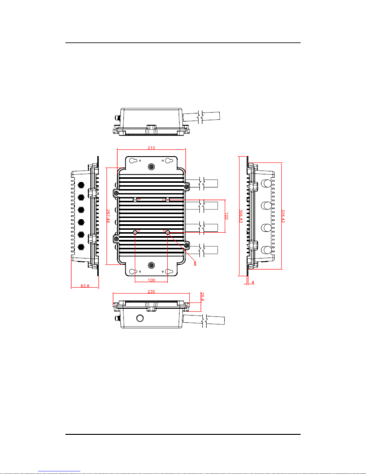
Dimension
210 mm (8.27") (W) x 366.83 mm (14.44") (D) x 83 mm (3.27”) (H)
1.2.4 Driver CD Contents
Ethernet
Chipset
Graphic
Intel Rapid Storage Technology
Audio
Intel
®
TXE Firmware
User Manual
Quick Manual
【Note】: All specifications and images are subject to change without notice.
Page 13
eBOX800-511-FL-FL Series user’s Manual
Introduction
5
1.3 Dimensions
The following diagrams show dimensions and outlines of the eBOX800-511-FL.
1.3.1 System Dimensions
Page 14
eBOX800-511-FL-FL Series user’s Manual
Introduction
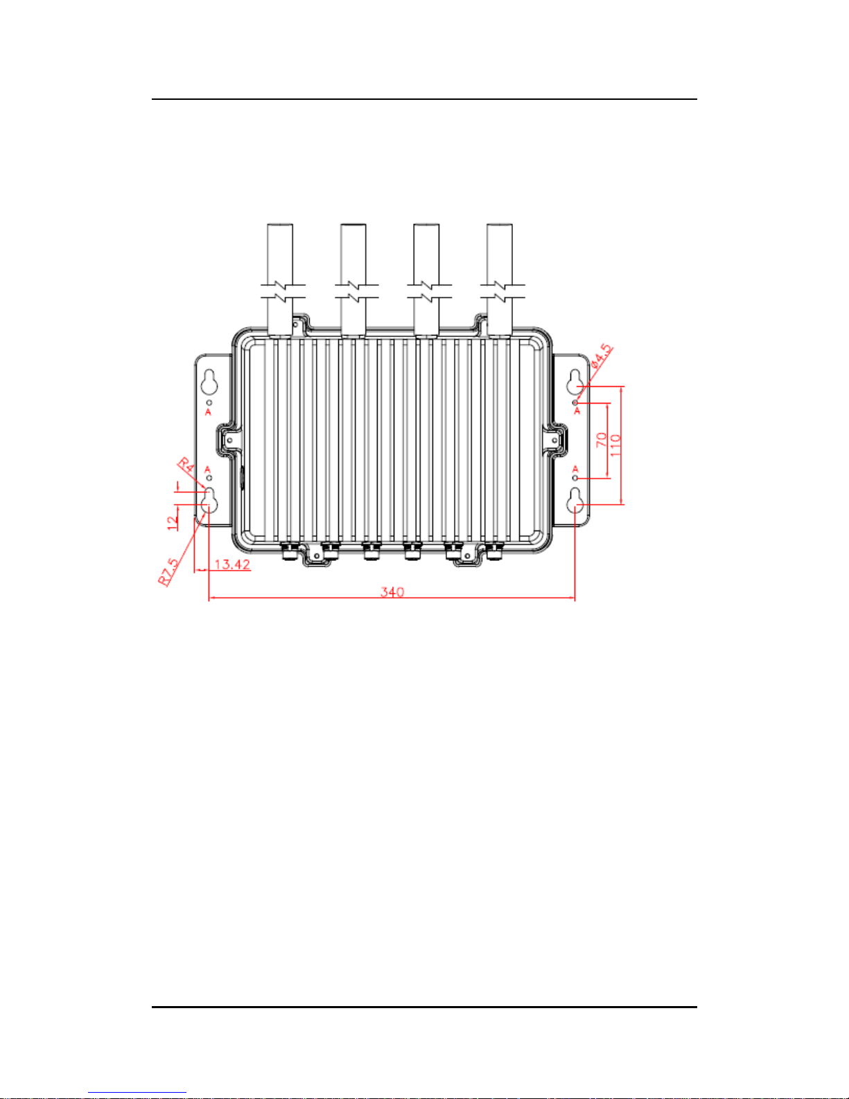
6
1.3.2 Wall-mount Bracket Dimensions
Page 15
eBOX800-511-FL-FL Series user’s Manual
Introduction
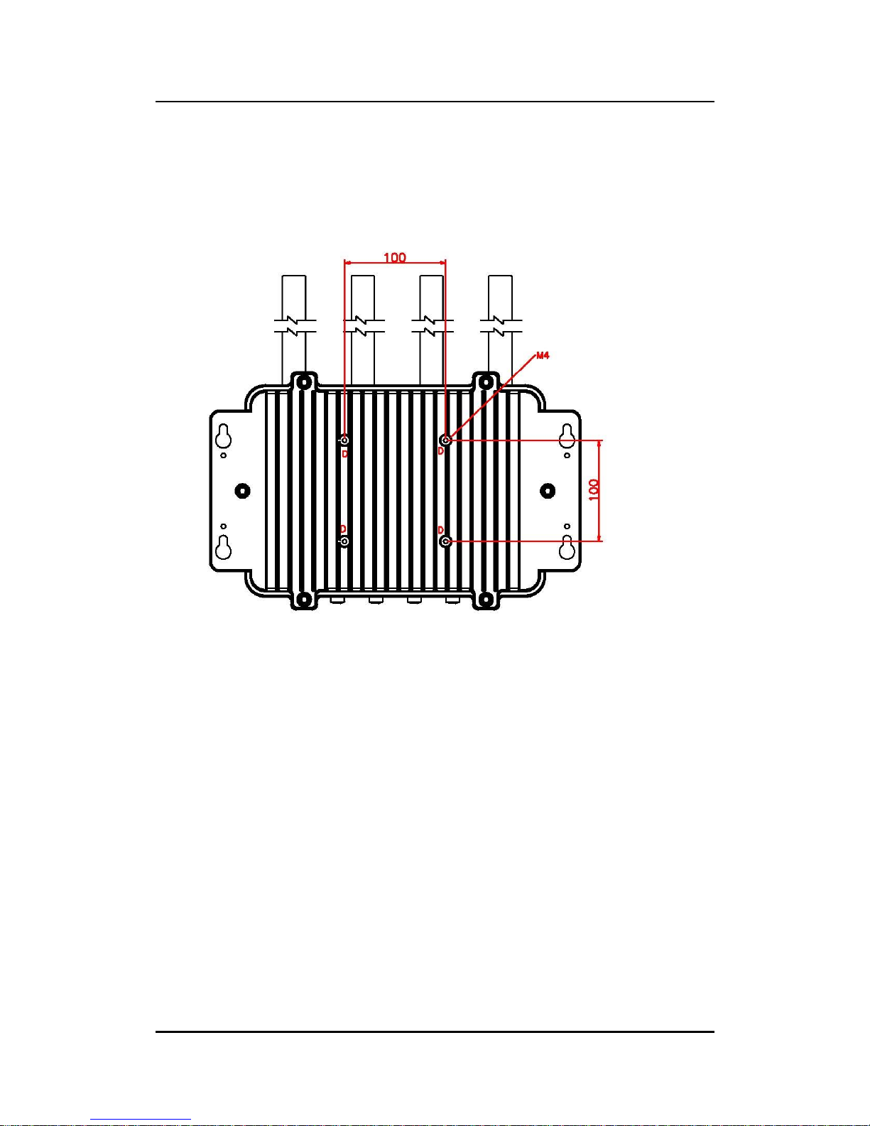
7
1.3.3 VESA-mount Bracket Dimensions
Page 16
eBOX800-511-FL-FL Series user’s Manual
Introduction
8
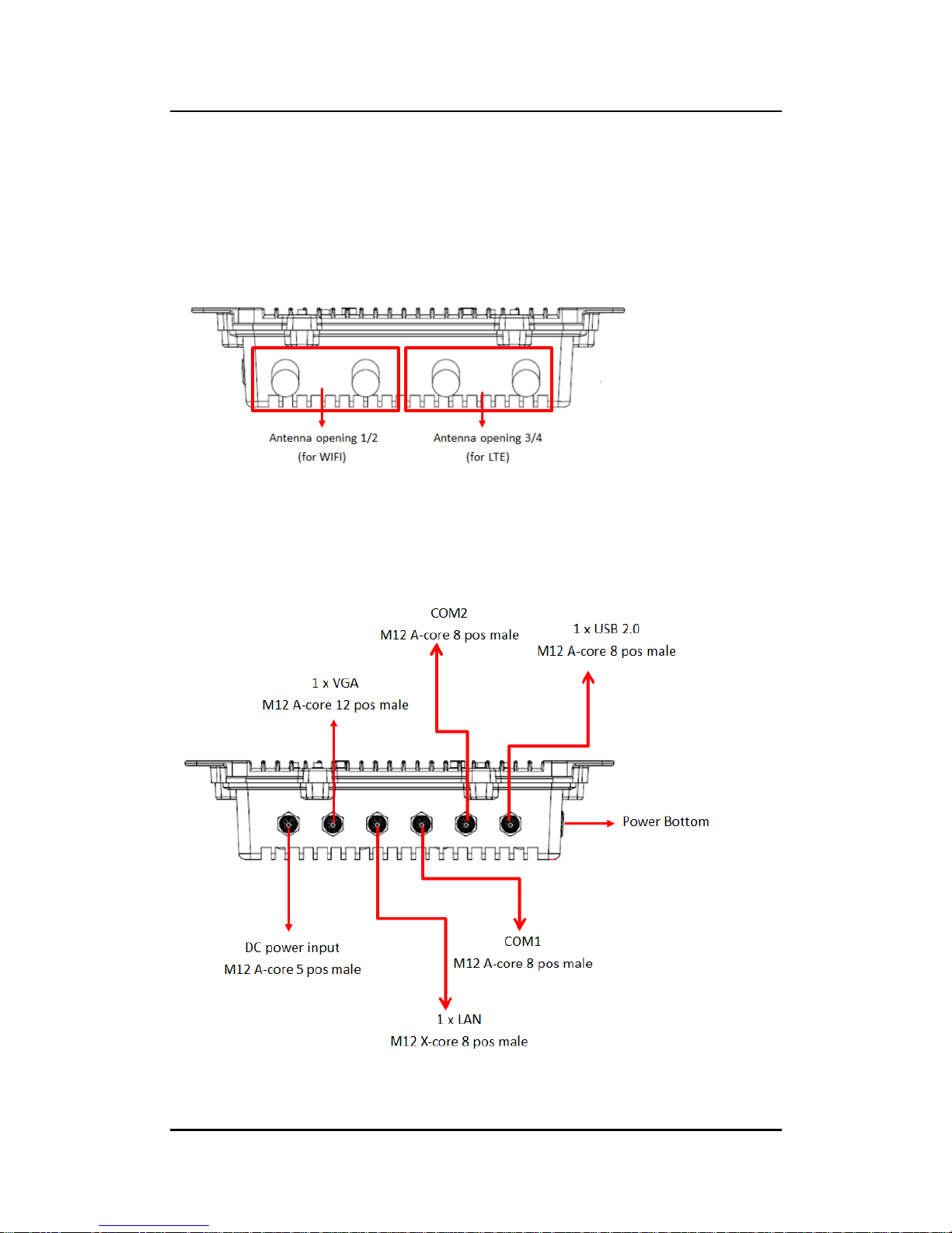
1.4 I/O Outlets
The following figures show I/O outlets on front of the eBOX800-511-FL.
Top View
Bottom View
Page 17

eBOX800-511-FL-FL Series user’s Manual
Introduction
9
1.5 Packing List
The eBOX800-511-FL comes with the following bundle package:
eBOX800-511-FL System Unit x 1
Quick Installation Guide x 1
DVD x 1 (For Driver and Manual)
waterproof PWR cable (L:1m) x 1
waterproof VGA cable (L:1.8m) x 1
waterproof USB 2.0 cable (L:1.8m) x 1
HDD mylar x 1
HDD screws x 2
HDD poron x 1
1.6 Model List
eBOX800-511-FL- DC-7300U
Rugged IP67-rated fanless embedded system with Intel
®
Core™ i5-7300U 2.6 GHz, VGA, 1 GbE LANs, 2 USBs, 2
COMs and 9~36VDC power input
eBOX800-511-FL- DC-3965U
Rugged IP67-rated fanless embedded system with Intel
®
Celeron
®
3965U 2.2 GHz, VGA, 1 GbE LANs, 2 USBs, 2
COMs and 9~36VDC power input
Please contact Axiomtek’s distributors immediately in case any abovementioned items are
missing.
Page 18

eBOX800-511-FL-FL Series user’s Manual
Introduction
10
This page is intentionally left blank.
Page 19
eBOX800-511-FL-FL Series user’s Manual
Hardware Installation
11
SECTION 2
HARDWARE INSTALLATION
The eBOX800-511-FL is convenient for various hardware configurations, such as DRAM,
HDD (Hard Disk Drive), SSD (Solid State Drive) and PCI Express Mini card modules. Section
2 contains guidelines for hardware installation.
【Note】:
Waterproof capability may be affected if a system is dissembled; under such
circumstances Axiomtek shall not be liable for any quality deterioration.
【Note】: Please refer to tightening torque below for all system screws:
HEX socket set screw: 7.5 kgf
HEX KEY specifications are shown below
N jack connector: 10 kgf
Page 20
eBOX800-511-FL-FL Series user’s Manual
Hardware Installation
12
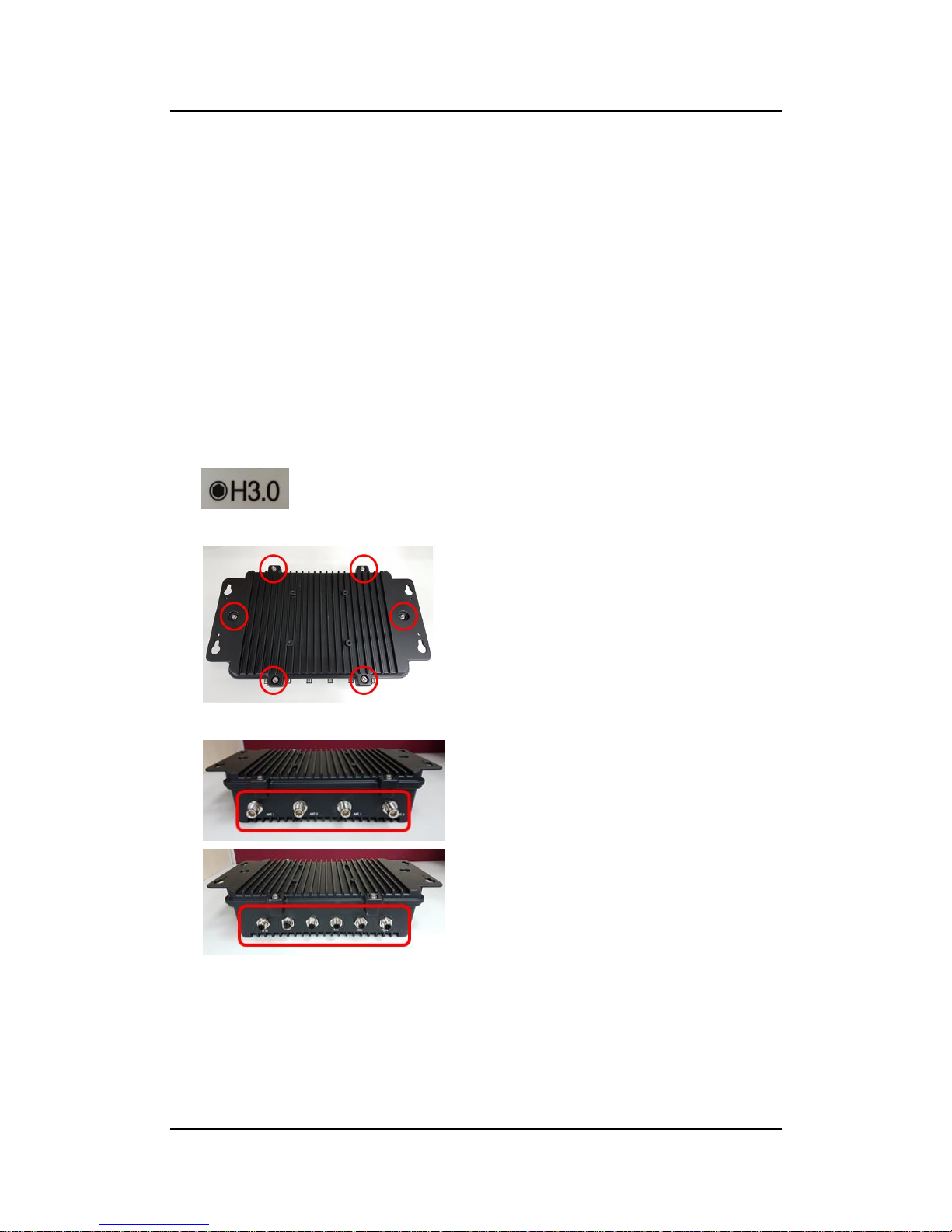
2.1 Installation of 2.5" SATA Device
Step 1 Turn off the system and unplug the power cord.
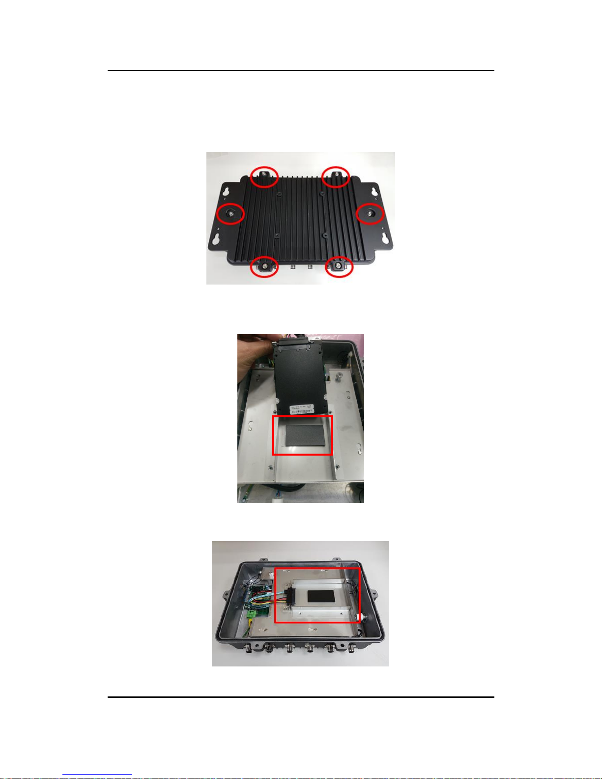
Step 2 Turn the system upside down to locate screws at the bottom and then
loosen all screws.
Step 3 Remove the bottom cover.
Note: For 7"mm HDD/SSD, please add a HDD poron before install the
HDD/SSD.
Step 4 Locate SSD/HDD within the red line as marked.
Please notice the direction of connector for HDD.
Page 21
eBOX800-511-FL-FL Series user’s Manual
Hardware Installation
13
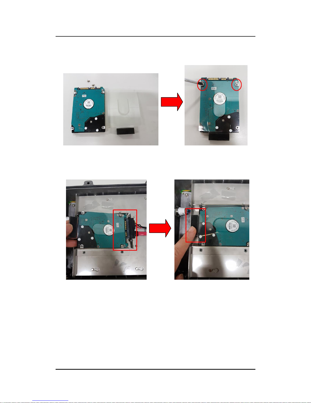
Step 5 Before install an SSD/HDD, please place the mylar on top of the
SSD/HDD and fasten two screws.
Step 6 Install the SSD/HDD into the HDD drive bay and push the poron down to
ensure the complete insertion of SSD/HDD.
Page 22
eBOX800-511-FL-FL Series user’s Manual
Hardware Installation
14
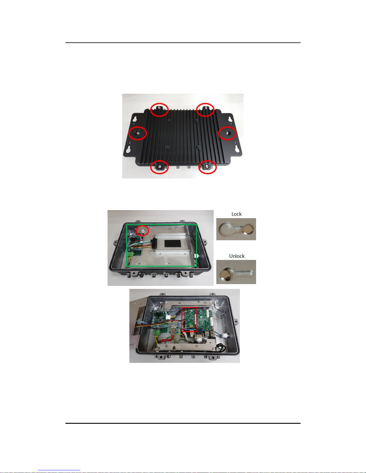
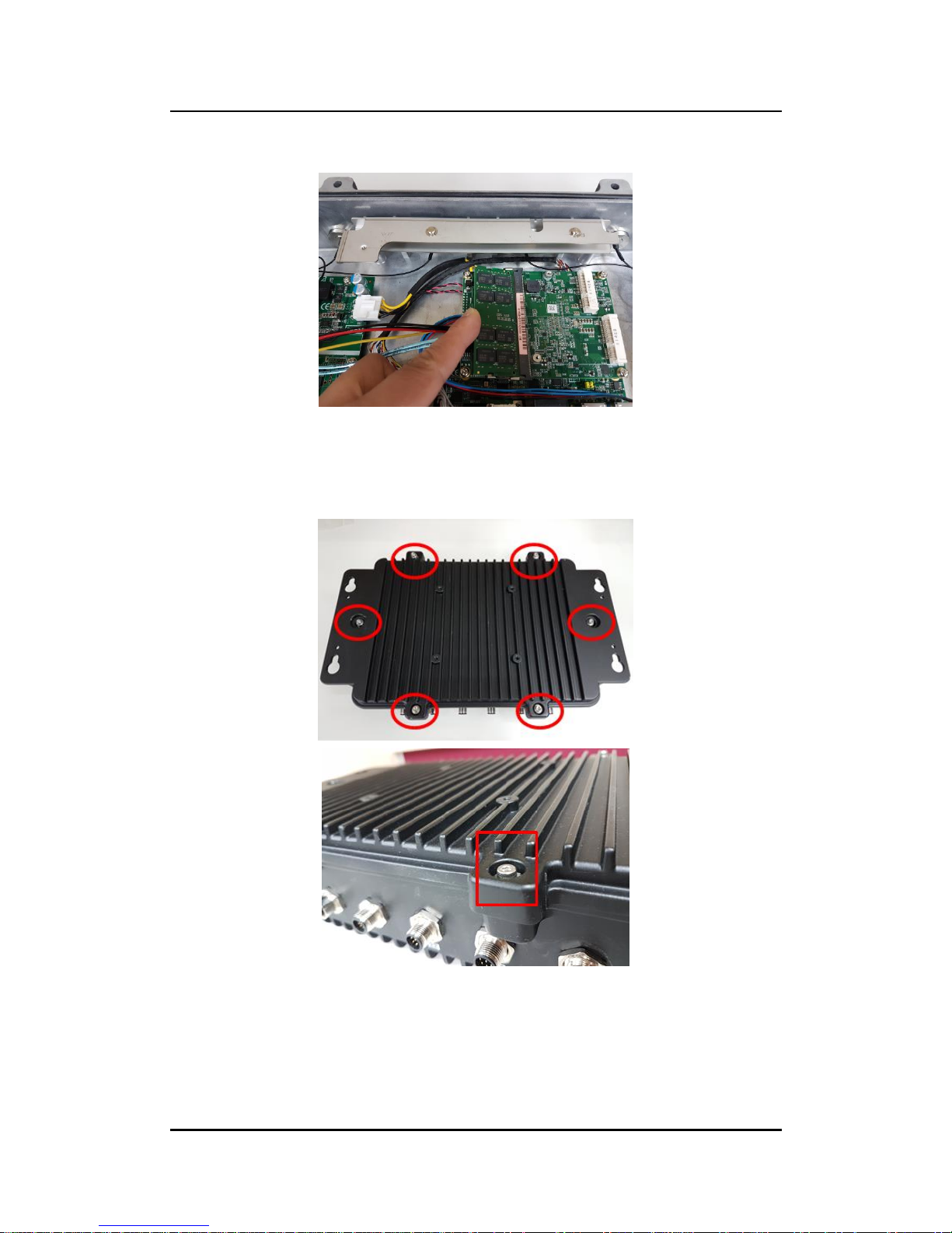
2.2 Installation of SO-DIMM
Step 1 Turn off the system and unplug the power cord.
Step 2 Six screws on the bottom heatsink are used to fasten the heatsink to
the chassis.
Step 3 Loosen the thumb screws to remove the metal plate then a SO -DIMM
socket on main board is visible.
Page 23
eBOX800-511-FL-FL Series user’s Manual
Hardware Installation
15
Step 4 Locate the memory module, insert a gold colored contact into the
socket and push the module two end latches till locked.
Step 5 Replace the metal plate, fasten the thumb screws, then put the bottom
cover and fasten six screws back onto the system.
【Note】: Make sure all screws are fastened.
Page 24
eBOX800-511-FL-FL Series user’s Manual
Hardware Installation
16
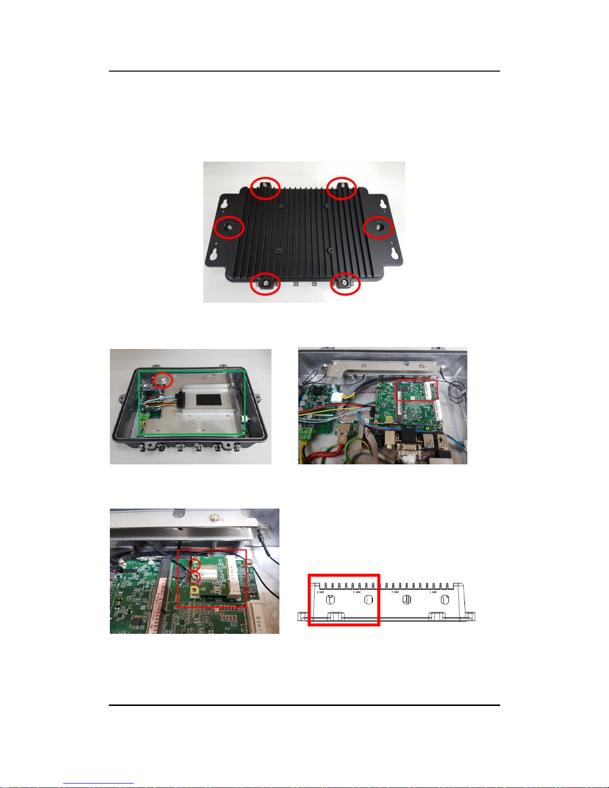
2.3 Installation of WI-FI Mini PCIe Module (half-size)
Step 1 Turn off the system and unplug the power cord.
Step 2 Turn the system upside down to locate screws at the bottom, and then
loosen all screws.
Step 3 Remove the metal plate by loosening the thumb screw, identify the WI-
FI, and then insert a WI-FI module.
Step 4 Connect RF Cable to I-PEX4 connector of WI-FI module and install
Antenna 1 and Antenna 2.
Page 25
eBOX800-511-FL-FL Series user’s Manual
Hardware Installation
17
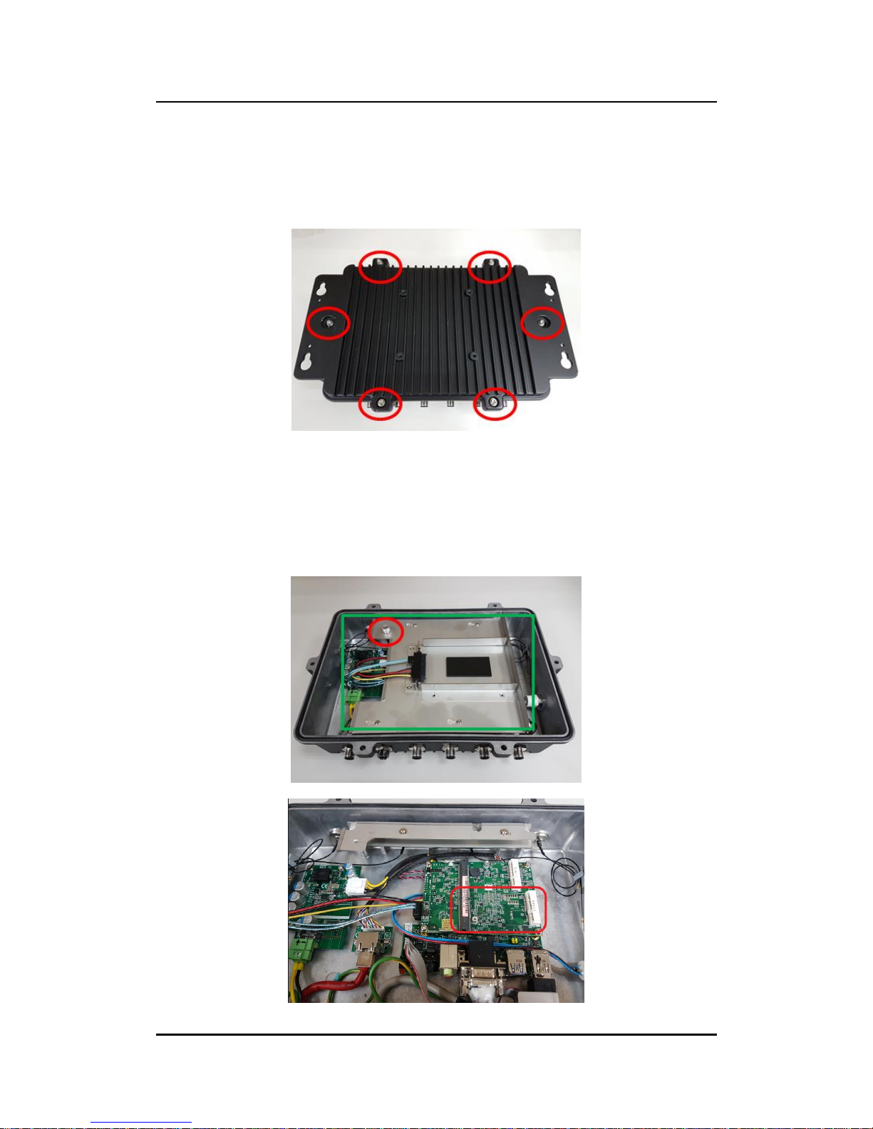
2.4 Installation of 3G/4G Mini PCIe Module (full-size)
Step 1 Turn off the system and unplug the power cord.
Step 2 Turn the system upside down to locate screws at the bottom, and then
loosen all screws.
Step 3 Remove the metal plate by loosening the thumb screws, identify the
socket, and then insert a 3G/4G module.
Note: eBOX800-511 doesn’t have SIM slot, please use 3G/4G module
with SIM on holder.
Note: Due to the full size PCIe mini card slot supports mSATA or PCIe
mini card, please choose either one to install, and refer to Section 4.4
for BIOS setting.
Page 26
eBOX800-511-FL-FL Series user’s Manual
Hardware Installation
18
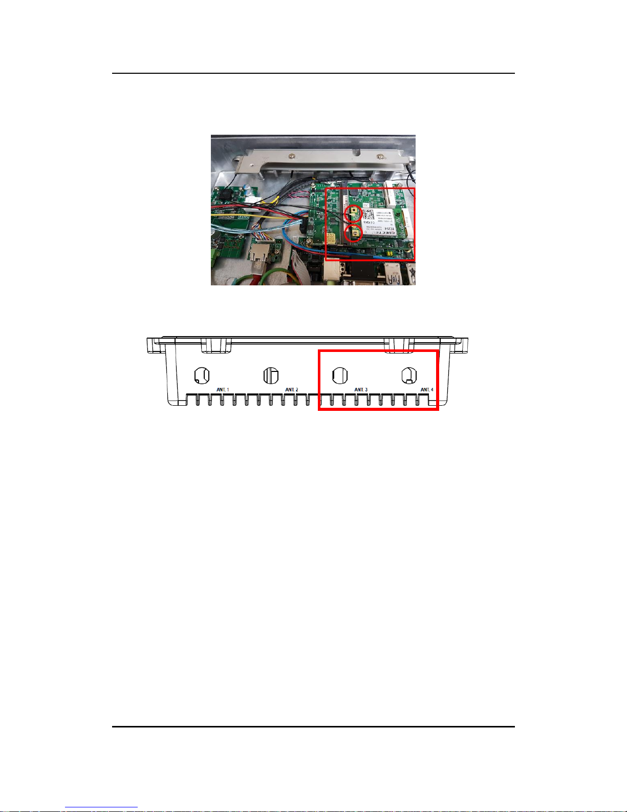
Step 4 Connect RF cable to I-PEX4 connector of 3G/4G Module and install
Antenna 3 and Antenna 4.
Page 27

eBOX800-511-FL-FL Series user’s Manual
Jumper & Connector Settings
19
SECTION 3
JUMPER & CONNECTOR SETTINGS
Proper jumper settings configure the eBOX800-511-FL to meet various application needs.
Hereby all jumpers settings along with their default settings are listed for devices onboard.
3.1 Locations of Jumpers & Connectors
PICO511 Top View
Page 28

eBOX800-511-FL-FL Series user’s Manual
Jumper & Connector Settings
20
PICO511 Bottom View
【 Note】 : It is strongly recommended that any unmentioned jumper settings
should not be modified without instructions by Axiomtek FAEs. Any
modifications without instructions might cause system failure.
Page 29

eBOX800-511-FL-FL Series user’s Manual
Jumper & Connector Settings
21
3.2 Summary of Jumper Settings
Proper jumper settings configure the eBOX800-511-FL to meet various application purposes.
A table of all jumpers and their default settings is listed below.
PICO511
Jumpers
Descriptions
Settings
JP2
Restore BIOS Optimal Defaults
Default: Normal Operation
1-2 Close
JP3
Auto Power On
Default: Enable
2-3 Close
【Note】: How to setup Jumpers
That a cap on a jumper is to “close” the jumper, whereas that offs a jumper is to “open” the
jumper.
[Open] [Closed] [Pin1-2 Closed]
Page 30

eBOX800-511-FL-FL Series user’s Manual
Jumper & Connector Settings
22
3.2.1 Restore BIOS Optimal Defaults (JP2)
Put jumper clip to pin 2-3 for a few seconds then move it back to pin 1-2. Doing this procedure
can restore BIOS optimal defaults.
3.2.2 Auto Power On (JP3)
If JP3 is enabled for power input, the system will be automatically power on without pressing
soft power button. If JP3 is disabled for power input, it is necessary to manually press soft
power button to power on the system.
Function
Setting
Normal (Default)
1-2 close
Restore BIOS optimal defaults
2-3 close
Function
Setting
Disable auto power on
1-2 close
Enable auto power on (Default)
2-3 close
Page 31

eBOX800-511-FL-FL Series user’s Manual
Jumper & Connector Settings
23
3.3 Connectors
Please refer to pin assignments below :
External Connectors
Sections
Serial Port
3.3.1
Ethernet Port
3.3.2
USB Port
3.3.3
DC Power Jack Connector
3.3.4
VGA Connector
3.3.5
Internal Connectors
Sections
Half-size PCI-Express Mini Card (on PICO511)
3.3.6
Full-size PCI-Express Mini Card or mSATA
Connector (on PICO511)
3.3.7
SATA Power Connector (CN6) (on PICO511)
3.3.8
CMOS connector (CN8) (on PICO511)
3.3.9
Ethernet connector (CN15)
3.3.10
Power connector (CN14)
3.3.11
Page 32

eBOX800-511-FL-FL Series user’s Manual
Jumper & Connector Settings
24
3.3.1 Serial Port (M12 A-Code 8 pos Male)
The following table shows pin assignments of this connector:
【Note】:Each port + 5V maximu m: 2A, +12V maxi mum: 1A .
Warning:
According to IP67 warrantee, please indicate specific COM1 settings at the time of placing
an order; don’t disassemble the system without authorization.
When receiving information via RS-422/485, if there appear some wrong codes,
please check whether RS-422/485 is connected to GND at both ends. The standard
method of RS-422/485 is to connect GND at both ends and make sure that receiver
and transmitter have the common ground.
Pins
RS-232
RS-422
RS-485
1
DCD
TX-
Data-
2
RXD
TX+
Data+
3
TXD
RX+
No use
4
DTR
RX-
No use
GND
GND
GND
5
DSR
No use
No use
6
RTS
No use
No use
7
CTS
No use
No use
8
RI
No use
No use
Page 33

eBOX800-511-FL-FL Series user’s Manual
Jumper & Connector Settings
25
3.3.2 Ethernet Port (M12 X-Code 8 pos Female)
Connectable via a M12 X-CODE LAN connector, the eBOX800-511-FL may be equipped with
a high performance Plug and Play Ethernet interface which is fully compliant with IEEE 802.3
standard.
Please refer to detailed pin assignment listed below:
3.3.3 USB Port (M12 A-Code 8 pos Male)
The USB is a Universal Serial Bus (compliant with USB 2.0 (480 Mbps)) connector on the rear
I/O. It is commonly used for installing USB peripherals such as keyboard, mouse, scanner, etc.
3.3.4 DC Power Jack Connector (M12 A-Code 5 pos Male)
Pins
Signals
Pins
Signals
L1
MDI0P
L5
MDI3P
L2
MDI0N
L6
MDI3N
L3
MDI1P
L7
MDI2N
L4
MDI1N
L8
MDI2P
Pins
Signals
Pins
Signals
1
USB VCC (+5V level)
5
USB VCC (+5V level)
2
USB #0_D-
6
USB #1_D-
3
USB #0_D+
7
USB #1_D+
4
GND
8
GND
Pins
Signals
1
9~36V
2
9~36V
3
GND
4
GND
5
Earth Ground
Page 34

eBOX800-511-FL-FL Series user’s Manual
Jumper & Connector Settings
26
3.3.5 VGA Connector (M12 A-Code 12 pos Male)
Pins
Signals
Pins
Signals
1
Red
7
Vertical Sync
2
Green
8
DDC CLK
3
Blue
9
VCC
4
DDC DATA
10
GND
5
Horizontal Sync
11
GND
6
DETECT
12
GND
Page 35

eBOX800-511-FL-FL Series user’s Manual
Jumper & Connector Settings
27
3.3.6 Half-size PCI-Express Mini Card Connector (SCN3)
This is a half-size PCI-Express Mini Card connector on the bottom side complying with PCIExpress Mini Card Spec. V1.2. It supports either PCI-Express or USB 2.0.
Pins
Signals
Pins
Signals
1
WAKE#
2
+3.3VSB
3
No use
4
GND
5
No use
6
+1.5V
7
CLKREQ#
8
No use
9
GND
10
No use
11
REFCLK-
12
No use
13
REFCLK+
14
No use
15
GND
16
No use
17
No use
18
GND
19
No use
20
W_DISABLE#
21
GND
22
PERST#
23
PE_RXN
24
+3.3VSB
25
PE_RXP
26
GND
27
GND
28
+1.5V
29
GND
30
SMB_CLK
31
PE_TXN
32
SMB_DATA
33
PE_TXP
34
GND
35
GND
36
USB_D4-
37
GND
38
USB_D4+
39
+3.3VSB
40
GND
41
+3.3VSB
42
No use
43
GND
44
No use
45
No use
46
No use
47
No use
48
+1.5V
49
No use
50
GND
51
No use
52
+3.3VSB
Page 36

eBOX800-511-FL-FL Series user’s Manual
Jumper & Connector Settings
28
3.3.7 Full-Size PCI-Express Mini Card Connector (SCN1)
This is a full-size PCI-Express Mini Card connector on the bottom side complying with PCIExpress Mini Card Spec. V1.2. It supports either PCI-Express, USB 2.0 or SATA (mSATA).
To enable or disable mSATA support, please refer to BIOS setting in section 4.4.
Pins
Signals
Pins
Signals
1
WAKE#
2
+3.3VSB
3
No use
4
GND
5
No use
6
+1.5V
7
CLKREQ#
8
No use
9
GND
10
No use
11
REFCLK-
12
No use
13
REFCLK+
14
No use
15
GND
16
No use
17
No use
18
GND
19
No use
20
W_DISABLE#
21
GND
22
PERST#
23
PE_RXN/
SATA_RXP
24
+3.3VSB
25
PE_RXP/
SATA_RXN
26
GND
27
GND
28
+1.5V
29
GND
30
SMB_CLK
31
PE_TXN/
SATA_TXN
32
SMB_DATA
33
PE_TXP/
SATA_TXP
34
GND
35
GND
36
USB_D4-
37
GND
38
USB_D4+
39
+3.3VSB
40
GND
41
+3.3VSB
42
No use
43
GND
44
No use
45
No use
46
No use
47
No use
48
+1.5V
49
No use
50
GND
51
No use
52
+3.3VSB
Page 37

eBOX800-511-FL-FL Series user’s Manual
Jumper & Connector Settings
29
3.3.8 SATA Power Connector (CN6)
The CN6 is a 4-pin (pitch=2.0mm) wafer connector, which is compliant with JST B4B-PH-K-S,
for SATA power interface.
3.3.9 CMOS Battery Connector (CN8)
This connector is for CMOS battery interface.
3.3.10 Ethernet Connector (CN15)
This is a JST BM16B-SRSS-TB 15-pin wafer connector for Ethernet interface. Gently connect
CN15 to AX93287 I/O board’s CN1.
1 15
Pins
Signals
1
+5V 2 GND
3
GND
4
+12V
Pins
Signals
1
+3.3V
2
GND
Pins
Signals
1
1000 LAN LED
2
100 LAN LED
3
GND
4
MDI3-
5
MDI3+
6
MDI1-
7
MDI2-
8
MDI2+
9
MDI1+
10
MDI0-
11
MDI0+
12
GND
13
LAN_VDD33
14
LAN_LINK_ACT
15
GND
1
Page 38

eBOX800-511-FL-FL Series user’s Manual
Jumper & Connector Settings
30
3.3.11 Power Connector (CN14)
The CN14 is a 4-pin (pitch=2.5mm) wafer connector in right angle for DC +12V input. Gently
connect CN14 to AX98251 power board’s CN1.
3.4 Waterproof Cables
The eBOX800-511-FL series uses specific M12 connector for waterproof as enclosed in the
accessory box; included in the box are also VGA, USB and Power cables. Please refer to
pictures below for cables pin definitions.
Power Cable
Pins
Signals
V+
9~36VDC power input
Earth Ground
GND
GND
GND
GND
Pins
Signals
1
+12V
2
+12V
3
GND
4
GND
Page 39

eBOX800-511-FL-FL Series user’s Manual
Jumper & Connector Settings
31
USB Cable
With two extended USB ports, the USB cable is combined with M12 connectors for waterproof.
VGA Cable
Page 40

eBOX800-511-FL-FL Series user’s Manual
Jumper & Connector Settings
32
This page is intentionally left blank.
Page 41

eBOX800-511-FL-FL Series user’s Manual
BIOS Setup Utility
33
SECTION 4
BIOS SETUP UTILITY
This section provides users with detailed descriptions in terms of how to set up basic system
configurations through the BIOS setup utility.
4.1 Starting
To enter the setup screens, follow the steps below:
1. Turn on the computer and press the <Del> key immediately.
2. After press the <Del> key, the main BIOS setup menu displays. Users can access to
other setup screens, such as the Advanced and Chipset menus, from the main BIOS
setup menu.
It is strongly recommended that users should avoid changing the chipset’s defaults. Both AMI
and system manufacturer have carefully set up these defaults that provide the best
performance and reliability.
4.2 Navigation Keys
The BIOS setup/utility uses a key-based navigation system called hot keys. Most of the BIOS
setup utility hot keys can be used at any time during the setup navigation process. These keys
include <F1>, <F2>, <Enter>, <ESC>, <Arrow> keys, and so on.
【 Note】: Some of the navigation keys differ from one screen to another.
Hot Keys
Descriptions
Left/Right
The Left and Right <Arrow> keys allow users to select a setup screen.
Up/Down
The Up and Down <Arrow> keys allow users to select a setup screen or
sub-screen.
+ Plus/Minus
The Plus and Minus <Arrow> keys allow users to change the field value of a
particular setup item.
Tab
The <Tab> key allows users to select setup fields.
F1
The <F1> key allows users to display the General Help screen.
F2
The <F2> key allows users to Load Previous Values.
F3
The <F3> key allows users to Load Optimized Defaults.
F4
The <F4> key allows users to save any changes they made and exit the
Setup. Press the <F4> key to save any changes.
Esc
The <Esc> key allows users to discard any changes they made and exit the
Setup. Press the <Esc> key to exit the setup without saving any changes.
Enter
The <Enter> key allows users to display or change the setup option listed
for a particular setup item. The <Enter> key can also allow users to display
the setup sub- screens.
Page 42

eBOX800-511-FL-FL Series user’s Manual
BIOS Setup Utility
34
4.3 Main Menu
The Main Menu screen is the first screen users see when entering the setup utility. Users can
always return to the Main setup screen by selecting the Main tab. System Time/Date can be
set up as described below. The Main BIOS setup screen is also shown below.
BIOS Information
Display the auto-detected BIOS information.
System Language
Choose the system default language.
System Date/Time
Use this option to change the system time and date. Highlight System Time or System Date
using the <Arrow> keys. Enter new values through the keyboard. Press the <Tab> key or the
<Arrow> keys to move between fields. The date must be entered in MM/DD/YY format. The
time is entered in HH:MM:SS format.
Access Level
Display the access level of current user.
Page 43

eBOX800-511-FL-FL Series user’s Manual
BIOS Setup Utility
35
4.4 Advanced Menu
The Advanced menu also allows users to set configuration of the CPU and other system
devices. Users can select any items in the left frame of the screen to go to sub menus:
► Hardware Monitor
► Utility Configuration
► ACPI Settings
► CPU Configuration
► SATA Configuration
► PCH-FW Configuration
► AMT Configuration
► USB Configuration
► Device Configuration
For items marked with “”, please press <Enter> for more options.
Page 44

eBOX800-511-FL-FL Series user’s Manual
BIOS Setup Utility
36
Hardware Monitor
Use this screen to select options for the ACPI configuration, and change the value of the
selected option. A description of the selected item appears on the right side of the screen.
This screen displays the temperature of system and CPU, system voltages (VBAT, +3.3V,
+3.3_SBY and +5V).
Page 45

eBOX800-511-FL-FL Series user’s Manual
BIOS Setup Utility
37
Utility Configuration
BIOS Flash Utility
BIOS flash utility configuration. For more detailed information, please refer to Appendix D.
Page 46

eBOX800-511-FL-FL Series user’s Manual
BIOS Setup Utility
38
ACPI Settings
ACPI Sleep State
The setting is S3 (Suspend to RAM); this option selects ACPI sleep state the system will enter
when suspend button is pressed.
Page 47

eBOX800-511-FL-FL Series user’s Manual
BIOS Setup Utility
39
CPU Configurations
This screen shows the CPU Configuration and you can change the value of the selected
option.
Intel (VMX) Virtualization Technology
Enable or disable Intel Virtualization Technology. When enabled, a VMM (Virtual Machine
Mode) can utilize the additional hardware capabilities. It allows a platform to run multiple
operating systems and applications independently, hence enabling a computer system to work
as several virtual systems.
Page 48

eBOX800-511-FL-FL Series user’s Manual
BIOS Setup Utility
40
SATA Configuration
In the SATA Configuration menu, you can see the current installed hardware in the SATA
ports. During system boot up, the BIOS automatically detects the presence of SATA devices.
SATA Mode Selection
The SATA mode is set to AHCI.
mSATA
Enable or disable mSATA feature.
Page 49

eBOX800-511-FL-FL Series user’s Manual
BIOS Setup Utility
41
PCH-HW
AMT Configuration
Use this screen to configure AMT parameters.
Page 50

eBOX800-511-FL-FL Series user’s Manual
BIOS Setup Utility
42
AMT BIOS Features
Enable or disable AMT (Active Management Technology) BIOS features. The default is
Enabled. After enabling, please refer to Appendix C for iAMT settings.
USB Configuration
USB Devices
Display all detected USB devices.
Page 51

eBOX800-511-FL-FL Series user’s Manual
BIOS Setup Utility
43
Device Configuration
A description of selected item appears on the right side of the screen. For items marked with
“”, please press <Enter> for more options.
Module Device Configuration
This option appears only if an I/O board is installed CN2 and CN3 (See Section 2.5.1). BIOS
will auto-detect all supported functions and you can use it to change settings on the I/O board.
The PICO511 supports the following I/O boards: AX93A00, AX93A01, AX93A02 and
AX93A09.
Page 52

eBOX800-511-FL-FL Series user’s Manual
BIOS Setup Utility
44
Module Device Configuration
This screen is available only if an I/O board with serial ports is connected. For items marked
with “”, please press <Enter> for more options.
AxiomType3 Super IO Configuration
Page 53

eBOX800-511-FL-FL Series user’s Manual
BIOS Setup Utility
45
Serial Port 1~2 Configuration
Set parameters related to serial port 1~2 on I/O board.
Page 54

eBOX800-511-FL-FL Series user’s Manual
BIOS Setup Utility
46
Serial Port 1 Configuration
COM Port Type
Use this item to set RS-232/422/485 communication mode.
Terminal Mode
Enable or disable terminal mode.
Page 55

eBOX800-511-FL-FL Series user’s Manual
BIOS Setup Utility
47
4.5 Chipset Menu
The Chipset menu allows users to change the advanced chipset settings. Users can select
any of the items in the left frame of the screen to go to the sub menus:
► PCH-IO Configuration
► System Agent (SA) Configuration
For items marked with “”, please press <Enter> for more options.
Page 56

eBOX800-511-FL-FL Series user’s Manual
BIOS Setup Utility
48
HD Audio
For items marked with “ , please press <Enter> for more options.
HD Audio Configuration
Use this item to set HD audio configuration.
Page 57

eBOX800-511-FL-FL Series user’s Manual
BIOS Setup Utility
49
System Agent (SA) Configuration
This screen allows users to configure parameters of South Bridge chipset.
Graphics Configuration
Use this item to open graphics configuration sub screen.
Memory Configuration
Use this item to refer to information related to system memory.
Page 58

eBOX800-511-FL-FL Series user’s Manual
BIOS Setup Utility
50
Primary IGFX Boot Display
Select the video device which will be activated during POST (Power-On Self Test).
Page 59

eBOX800-511-FL-FL Series user’s Manual
BIOS Setup Utility
51
Memory information
This screen shows the system memory information.
Page 60

eBOX800-511-FL-FL Series user’s Manual
BIOS Setup Utility
52
Security Menu
Administrator Password
This item indicates whether an administrator password has been set (installed or uninstalled).
User Password
This item indicates whether a user password has been set (installed or uninstalled).
Page 61

eBOX800-511-FL-FL Series user’s Manual
BIOS Setup Utility
53
4.6 Boot Menu
The Boot menu allows users to change boot options of the system.
Bootup NumLock State
Use this item to select the power-on state for the keyboard NumLock.
Quiet Boot
Select to display either POST output messages or a splash screen during boot-up.
Legacy PXE OpROM
Use this item to enable or disable the boot ROM function of the onboard LAN chip when the
system boots up.
Boot Option Priorities
These are settings for boot priority. Specify the boot device priority sequence from the
available devices.
Hard Drive BBS Priorities
These are settings for configuring the order for a specific device group. These options are only
visible if at least one device for this group is present.
Page 62

eBOX800-511-FL-FL Series user’s Manual
BIOS Setup Utility
54
4.7 Save & Exit Menu
The Save & Exit menu allows users to load system configurations with optimal or fail-safe
default values.
Save Changes and Exit
When users have completed the system configuration changes, select this option to leave
Setup and return to Main Menu. Select Save Changes and Exit from the Save & Exit menu
and press <Enter>. Select Yes to save changes and exit.
Discard Changes and Exit
Select this option to quit Setup without making any permanent changes to the system
configurations and return to Main Menu. Select Discard Changes and Exit from the Save &
Exit menu and press <Enter>. Select Yes to discard changes and exit.
Save Changes and Reset
When completed the system configuration changes, select this option to leave Setup and
reboot the computer so the new system configurations take effect. Select Save Changes and
Reset from the Save & Exit menu and press <Enter>. Select Yes to save changes and reset.
Discard Changes and Reset
Select this option to quit Setup without making any permanent changes to the system
configuration and reboot the computer. Select Discard Changes and Reset from the Save &
Exit menu and press <Enter>. Select Yes to discard changes and reset.
Page 63

eBOX800-511-FL-FL Series user’s Manual
BIOS Setup Utility
55
Save Changes
When completed the system configuration changes, select this option to save changes. Select
Save Changes from the Save & Exit menu and press <Enter>. Select Yes to save changes.
Discard Changes
Select this option to quit Setup without making any permanent changes to the system
configurations. Select Discard Changes from the Save & Exit menu and press <Enter>. Select
Yes to discard changes.
Restore Defaults
It automatically sets all Setup options to a complete set of default settings when users select
this option. Select Restore Defaults from the Save & Exit menu and press <Enter>.
Save as User Defaults
Select this option to save system configuration changes done so far as User Defaults. Select
Save as User Defaults from the Save & Exit menu and press <Enter>.
Restore User Defaults
It automatically sets all Setup options to a complete set of User Defaults when users select
this option. Select Restore User Defaults from the Save & Exit menu and press <Enter>.
Boot Override
Select a drive to immediately boot that device regardless of the current boot order.
Page 64

eBOX800-511-FL-FL Series user’s Manual
BIOS Setup Utility
56
This page is intentionally left blank.
Page 65

eBOX800-511-FL-FL Series user’s Manual
Watchdog Timer 57
APPENDIX A
WATCHDOG TIMER
A.1 About Watchdog Timer
After the system stops working for a while, it can be auto-reset by the watchdog timer. The
integrated watchdog timer can be set up in the system reset mode by program.
A.2 How to Use Watchdog Timer
Assembly sample code :
mov dx,fa10 ; 5 seconds (Maximum is 65535 seconds; fill in
; 0xFA10 and 0xFA11 register, ex:
0xFA11=0x01,
; 0xFA10=0x68 means 360 seconds)
mov al,05
out dx,al
mov dx,fa12 ; Enable WDT
mov al,01
out dx,al
Page 66

eBOX800-511-FL-FL Series user’s Manual
58 Watchdog Timer
This page is intentionally left blank.
Page 67

eBOX800-511-FL-FL Series user’s Manual
iAMT Settings
59
APPENDIX B
iAMT SETTINGS
The Intel® Active Management Technology (Intel® iAMT) has decreased a major barrier to IT
efficiency that uses built-in platform capabilities and popular third-party management and
security applications to allow IT a better discovering, healing, and protection their networked
computing assets.
In order to utilize Intel® iAMT you must enter the ME BIOS (<Ctrl + P> during system startup),
change the ME BIOS password, and then select “Intel® iAMT” as the manageability feature.
B.1 Entering MEBx
1. Go to BIOS to enable iAMT function (see section 4.4).
2. Exit from BIOS after starting iAMT, and press <Ctrl + P> to enter MEBx Setting.
Note
It is better to press <Ctrl + P> before the screen popping out.
B.2 Set and Change Password
1. You will be asked to set a password when first log in. The default password is “admin”.
Page 68

eBOX800-511-FL-FL Series user’s Manual
iAMT Settings
60
2. You will be asked to change the password before setting ME.
3. You must confirm your new password while revising. The new password must contain:
(example: !!11qqQQ) (default value).
Eight characters
One upper case
One lower case
One number
One special symbol, such as ! 、 $ or ; , (、 " , excepted)
Underline ( _ ) and space are valid characters for password, but they won’t make higher
complexity.
4. From Main Menu, select ME General Settings to get into ME Platform Configuration
screen. In this screen you can modify Local FW Update setting.
5. Return to Main Menu.
Page 69

eBOX800-511-FL-FL Series user’s Manual
iAMT Settings
61
B.3 iAMT Configuration
1. From Main Menu, select Intel
®
Standard Manageability Configuration and press <Enter>.
2. Set Manageability Feature Selection to Enabled.
Page 70

eBOX800-511-FL-FL Series user’s Manual
iAMT Settings
62
SOL/Storage Redirection/KVM
This screen is for enabling or disabling Serial-over-LAN (SOL)/Storage
Redirection/Keyboard Video Mouse (KVM) functionality.
User Consent
i
Page 71

eBOX800-511-FL-FL Series user’s Manual
iAMT Settings
63
User Opt-in
Configure this item when user consent should be required.
Opt-in Configurable from Remote IT
Enable or disable remote change capability of user consent feature.
Network Setup
1. From Intel® AMT Configuration Menu, select Network Setup.
2. Select ME Network Name Settings to set computer host and domain name.
Page 72

eBOX800-511-FL-FL Series user’s Manual
iAMT Settings
64
3. Select TCP/IP to get into Network interface. Get into DHCP Mode and set it to Disabled.
Page 73

eBOX800-511-FL-FL Series user’s Manual
iAMT Settings
65
4. If DHCP Mode is disabled, set the following settings:
IP address
Subnet mask
5. Go back to Intel® iAMT Configuration, then select Activate Network Access and press
<Enter>.
Page 74

eBOX800-511-FL-FL Series user’s Manual
iAMT Settings
66
6. Exit from MEBx after completing the iAMT settings.
Remote Setup and Configuration
1. Select TLS PKI to get into remote configuration screen. Then select Start Configuration
to activate it.
Page 75

eBOX800-511-FL-FL Series user’s Manual
iAMT Settings
67
2. Select Manage Hashes to add, delete and activate hash.
Page 76

eBOX800-511-FL-FL Series user’s Manual
iAMT Settings
68
Power Control
AMT ON in Host Sleep States
Select the appropriate AMT ON in Host Sleep States setting. Options are ON in S0 and
ON in S0, ME Wake in S3, S4-5 (AC only).
Idle Timeout
This is timeout value for Wake_On_ME in minutes. It must be set to a non-zero value.
Page 77

eBOX800-511-FL-FL Series user’s Manual
iAMT Settings
69
B.4 iAMT Web Console
1. From a web browser, please type http://(IP ADDRESS):16992, which connects to iAMT
Web.
Example: http://10.1.40.214:16992
2. To log on, you will be required to type in username and password for access to the Web.
USER: admin (default value)
PASS: (MEBx password)
Page 78

eBOX800-511-FL-FL Series user’s Manual
iAMT Settings
70
3. Enter the iAMT Web.
4. Click Remote Control, and select commands on the right side.
5. When you have finished using the iAMT Web console, close the Web browser.
Page 79

eBOX800-511-FL-FL Series user’s Manual
BIOS Flash Utility
71
APPENDIX C
BIOS Flash Utility
The BIOS Flash utility is a new helpful function in BIOS setup program. With this function you
can easily update system BIOS without having to enter operating system. In this appendix you
may learn how to do it in just a few steps. Please read and follow the instructions below
carefully.
1. In your USB flash drive, create a new folder and name it “Axiomtek”, see figure below.
2. Copy BIOS ROM file (e.g. PICO511.005) to “Axiomtek” folder.
3. Insert the USB flash drive to your system.
Page 80

eBOX800-511-FL-FL Series user’s Manual
BIOS Flash Utility
72
4. Enter BIOS setup menu and go to Advanced\Utility Configuration. Select BIOS Flash
Utility and press <Enter>.
5. BIOS automatically detect all USB drive(s) attached to the system. In this example only
one USB drive is attached to the system. That’s why, you can see only one device is
displayed in figure below.
6. Select the USB drive containing BIOS ROM file you want to update using the <> or
<> key. Then press <Enter> to get into “Axiomtek” folder.
Page 81

eBOX800-511-FL-FL Series user’s Manual
BIOS Flash Utility
73
7. Now you can see the BIOS ROM file on the screen, press <Enter> to select.
8. Select Start to flash system BIOS option to begin updating procedure.
PICO511.005
Page 82

eBOX800-511-FL-FL Series user’s Manual
BIOS Flash Utility
74
9. Please wait while BIOS completes the entire flash update process: erase data, write new
data and verify data.
10. When you see the following figure, press <Enter> to finish the update process. After that
the system will shut down and restart immediately.
Page 83

eBOX800-511-FL-FL Series user’s Manual
IO Board
75
APPENDIX D
IO BOARD
The AX93287/AX93A00 is an I/O expansion board which is suggested to attach carefully to
PICO511. Its specifications and detailed information are given in this appendix.
AX93287 TOP View AX93287 Side View
Ethernet Connector from AX93287 (CN1)
Note: CN1 is suggested to connect CN3 on AX92902 via LAN cable.
Pins
Signals
Pins
Signals
1
100_LAN_LED
9
MDI1-
2
1000_LAN_LE
D
10
MDI1+
3
NC
11
NC 4 MDI3-
12
MDI0-
5
MDI3+
13
MDI0+
6
NC
14
NC 7 MDI2-
15
LINK_ACT
8
MDI2+
16
VDD3
Pins
Signals
Pins
Signals
L1
MDI0+
L5
MDI2+
L2
MDI0-
L6
MDI2-
L3
MDI1+
L7
MDI3+
L4
MDI1-
L8
MDI3-
A
100 LAN LED (Green) / 1000 LAN LED
(Orange)
B
Active LED (Yellow)
Page 84

eBOX800-511-FL-FL Series user’s Manual
IO Board
76
AX93A00 TOP View
CN9
CN5
CN10
JP1
JP2
D18
CN3
CN8
JP3
CN4
CN6
CN7
CN1
CN2
1
1
1
AX93A00 side view
AX93A00
Jumpers
Descriptions
Settings
JP1
USB port 0 and 1
Power Selection
+5V_SBY (Default)
1-2 Close
+5V
2-3 Close
JP2
USB port 2 and 3
Power Selection
+5V_SBY (Default)
1-2 Close
+5V
2-3 Close
JP3
COM1 Data/Power
Selection
Power: Set COM1 pin 9 to +12V level
1-3 Close
RS-232 Data: Set COM1 pin 9 to RI
(Default)
3-5 Close
Power: Set COM1 pin 1 to +5V level
2-4 Close
RS-232 Data: Set COM1 pin 1 to DCD
(Default)
4-6 Close
COM 1 Connector (CN8)
Pins
RS-232
RS-422
RS-485
1
DCD
TX-
Data-
2
RXD
TX+
Data+
3
TXD
RX+
No use
4
DTR
RX-
No use
5
GND
No use
No use
6
DSR
No use
No use
7
RTS
No use
No use
8
CTS
No use
No use
9
RI
No use
No use
Page 85

eBOX800-511-FL-FL Series user’s Manual
IO Board
77
COM 2 Wafer Connector (CN4)
Pins
RS-232
RS-422
RS-485
1
DCD
TX-
Data-
2
DSR
No use
No use
3
RXD
TX+
Data+
4
RTS
No use
No use
5
TXD
RX+
No use
6
CTS
No use
No use
7
DTR
RX-
No use
8
RI
No use
No use
9
GND
No use
No use
10
No use
No use
No use
 Loading...