

Page 1

eBOX670-891-FL Series
Embedded System
User’s Manual
Page 2

ii
Disclaimers
This manual has been carefully checked and believed to contain accurate information.
Axiomtek Co., Ltd. assumes no responsibility for any infringements of patents or any third
party’s rights, or any liability arising from such uses.
Axiomtek does not warrant or assume any legal liability or responsibility for the accuracy,
completeness or usefulness of any information in this document. Axiomtek does not make any
commitment to update any information in this manual.
Axiomtek reserves the right to change or revise this document and/or product at any time
without notice.
No part of this document may be reproduced, stored in a retrieval system, or transmitted in
any forms or by any means, electronic, mechanical, photocopying, recording, among others,
without prior written permissions of Axiomtek Co., Ltd.
Copyright 2016 Axiomtek Co., Ltd.
All Rights Reserved
Nov 2016, Version A1
Printed in Taiwan
Page 3

iii
Safety Precautions
Before getting started, please read the following important safety precautions.
1. The eBOX670-891-FL does not come with an operating system which must be loaded
first before installation of any software into the computer.
2. Be sure to ground yourself to prevent static charge when installing any internal
components. Use a wrist grounding strap and place all electronic components in any
static-shielded devices. Most electronic components are sensitive to static electrical
charge.
3. Disconnect the power cord from the eBOX670-891-FL prior to making any installation.
Be sure both the system and all external devices are turned OFF. Sudden surge of
power could ruin sensitive components. Make sure the eBOX670-891-FL is properly
grounded.
4. Make sure the voltage of the power source is correct before connecting it to any power
outlet.
5. Turn Off system power before cleaning. Clean the system using a cloth only. Do not
spray any liquid cleaner directly onto the screen.
6. Do not leave equipment in an uncontrolled environment where the storage temperature
is below -40℃ or above 80℃ as it may damage the equipment.
7. Do not open the system’s back cover. If opening the cover for maintenance is a must,
only a trained technician is allowed to do so. Integrated circuits on computer boards are
sensitive to static electricity. To avoid damaging chips from electrostatic discharge,
observe the following precautions:
Before handling a board or integrated circuit, touch an unpainted portion of the
system unit chassis for a few seconds. This will help discharge any static electricity on
human body.
When handling boards and components, wear a wrist grounding strap available from
most electronic component stores.
Page 4

iv
Classifications
1. Degree of production against electric shock: not classified
2. Degree of protection against ingress of water: IP40
3. Equipment not suitable for use in the presence of a flammable anesthetic mixture with air,
oxygen or nitrous oxide.
4. Mode of operation: Continuous
Page 5

v
General Cleaning Tips
Please keep the following precautions in mind while understanding the details fully before and
during any cleaning of the computer and any components within.
A piece of dry cloth is ideal to clean the device.
1. Be cautious of any tiny removable components when using a vacuum cleaner to absorb
dirt on the floor.
2. Turn the system off before clean up the computer or any components within.
3. Avoid dropping any components inside the computer or getting circuit board damp or wet.
4. For cleaning, be cautious of all kinds of cleaning solvents or chemicals which may cause
allergy to certain individuals.
5. Keep foods, drinks or cigarettes away from the computer.
Cleaning Tools:
Although many companies have created products to help improve the process of cleaning
computer and peripherals, users can also use house hold items accordingly for cleaning.
Listed below are items available for cleaning computer or computer peripherals.
Pay special attention to components requiring designated products for cleaning as
mentioned below.
Cloth: A piece of cloth is the best tool to use when rubbing up a component. Although
paper towels or tissues can be used on most hardware as well, it is recommended to use
a piece of cloth.
Water or rubbing alcohol: A piece of cloth may be somewhat moistened with water or
rubbing alcohol before being rubbed on the computer. Unknown solvents may be harmful
to plastic parts.
Absorb dust, dirt, hair, cigarette and other particles outside of a computer can be one of
the best methods of cleaning a computer. Over time these items may restrict the airflow
in a computer and cause circuitry to corrode.
Cotton swabs: Cotton swaps moistened with rubbing alcohol or water are applicable to
reach areas in keyboard, mouse and other areas.
Foam swabs: If possible, it is better to use lint free swabs such as foam swabs.
.
【Note】: It is strongly recommended that customer should shut down the system before
start to clean any single components.
Please follow the steps below:
1. Close all application programs;
2. Close operating software;
3. Turn off power switch;
4. Remove all devices;
5. Pull out power cable.
Page 6

vi
Scrap Computer Recycling
Please inform the nearest Axiomtek distributor as soon as possible for suitable solutions in
case computers require maintenance or repair; or for recycling in case computers are out of
order.
Trademarks Acknowledgments
Axiomtek is a trademark of Axiomtek Co., Ltd.
IBM, PC/AT, PS/2, VGA are trademarks of International Business Machines
Corporation. Intel® and Pentium® are registered trademarks of Intel Corporation.
MS-DOS, Microsoft C and QuickBasic, Windows 10, Windows 8.1, Windows 8,
Windows 7, Windows XPE, Windows XP, Windows CE embedded, Linux are
trademarks of Microsoft Corporation.
Other brand names and trademarks are the properties and registered brands of their
respective owners.
Page 7

vii
Table of Contents
Disclaimers ............................................................................................................... ii
Safety Precautions .................................................................................................. iii
Classifications ......................................................................................................... iv
General Cleaning Tips ............................................................................................. v
Scrap Computer Recycling ..................................................................................... vi
SECTION 1 INTRODUCTION .................................................................................... 1
1.1 General Descriptions ........................................................................... 1
1.2 System Specifications ......................................................................... 2
1.2.1 CPU ...................................................................................................................... 2
1.2.2 I/O System ........................................................................................................... 3
1.2.3 System Specifications ........................................................................................ 4
1.2.4 Driver CD Contents ............................................................................................. 4
1.3 Dimensions .......................................................................................... 5
1.3.1 System Dimensions ............................................................................................ 5
1.3.2 Wall-mount Bracket Dimensions ....................................................................... 6
1.4 I/O Outlets ............................................................................................ 7
1.5 Packing List .......................................................................................... 8
1.6 Model List ............................................................................................. 8
SECTION 2 HARDWARE INSTALLATION............................................................. 9
2.1 Installation of CPU .............................................................................. 9
2.2 Installation of 2.5" SATA Device ...................................................... 12
2.3 Installation of SO-DIMM ..................................................................... 14
2.4 Installation of CFastTM Module ......................................................... 16
2.5 Installation of Mini PCIe Module (full-size) ...................................... 17
2.6 Installation of Flexible I/O Modules .................................................. 18
SECTION 3 JUMPER & CONNECTOR SETTINGS............................................ 21
3.1 Locations of Jumpers & Connectors ............................................... 21
3.2 Summary of Jumper Settings .......................................................... 23
3.2.1 Restore BIOS Optimal Defaults (JP1) ............................................................. 23
3.3 Connectors ....................................................................................... 24
3.3.1 DC-in Phoenix Power Connector .................................................................... 25
3.3.2 HDMI Connector ................................................................................................ 25
3.3.3 DisplayPort Connector ..................................................................................... 26
3.3.4 Serial Port Connector (COM 1~COM 4) .......................................................... 26
3.3.5 USB 3.0 Connector ........................................................................................... 27
3.3.6 Ethernet Connector (LAN1~LAN4) .................................................................. 27
3.3.7 USB 2.0 Connector ........................................................................................... 28
3.3.8 Audio Connector ............................................................................................... 28
3.3.9 Digital I/O ........................................................................................................... 29
3.3.10 ATX Power On/OFF .......................................................................................... 30
3.3.11 Reset Button .................................................................................................... 30
3.3.12 Remote Power Switch Connector ................................................................... 30
Page 8

viii
3.3.13 AT/ATX Switch .................................................................................................. 30
3.3.14 CFast™ Socket ................................................................................................. 31
3.3.15 SATA Connector (SATA 1 & 2) ........................................................................ 32
3.3.16 SATA Power Connector ................................................................................... 32
3.3.17 SIM Card Slots (SCN1) ..................................................................................... 32
3.3.18 Full-Size PCI Express Mini Card Slot (SCN2 & SCN3) .................................. 33
SECTION 4 BIOS SETUP UTILITY ........................................................................ 35
4.1 Starting ............................................................................................... 35
4.2 Navigation Keys ................................................................................. 35
4.3 Main Menu .......................................................................................... 36
4.4 Advanced Menu .................................................................................. 37
4.5 Chipset Menu ..................................................................................... 53
4.6 Boot Menu .......................................................................................... 58
4.7 Save & Exit Menu ............................................................................... 59
APPENDIX A WATCHDOG TIMER ........................................................................ 61
About Watchdog Timer .................................................................................... 61
Sample Program ................................................................ ................................ 62
APPENDIX B PROGRAMMABLE LED ................................................................. 63
APPENDIX C PROGRAMMABLE DIGITAL I/O ................................................... 65
APPENDIX D CONFIGURING SATA FOR RAID................................................. 67
D.1 Configuring SATA Hard Drive(s) for RAID ........................................ 67
APPENDIX E iAMT SETTINGS .............................................................................. 75
E.1 Entering MEBx ................................................................................... 75
E.2 Set and Change Password ................................................................ 75
E.3 iAMT Settings ..................................................................................... 77
E.4 iAMT Web Console ............................................................................. 80
Page 9

eBOX670-891-FL Series user’s Manual
Introduction
1
SECTION 1
INTRODUCTION
This section contains general information and detailed specifications of the
eBOX670-891-FL.Section 1 consist of the following sub-sections:
General Descriptions
System Specifications
Dimensions
I/O Outlets
Packing List
Model List
1.1 General Descriptions
A fanless embedded system with 6th generation Intel
®
Core™ i7/i5/i3 and Celeron
®
processor (formally codename: Skylake) processor with flexible I/O design. To fulfill
different application needs, the flexible embedded system supports WE8S, WES7,
Windows® 10 and Linux, and it can be wall-mounted and Din-rail mounted by optional
requests.
The eBOX670-891-FL is built with an IP40-rated heavy-duty aluminum extrusion,
enabling reliable operation in harsh environments. Moreover, a wide range 9 to 36V
DC power input with power protection, -30°C to +60°C extended temperature. To
highly reduce deployment time, this fanless embedded PC supports one optional I/O
door for customers to easily install additional I/O output. It is perfectly suitable for
any industrial grade applications.
Page 10

eBOX670-891-FL Series user’s Manual
Introduction
2
Features
LGA1151 socket 6th generation Intel® Core™ i7/i5/i3 & Celeron® processor
(Skylake) with Intel®Q170
Supports Jumbo Frame (9.5k), WoL, PXE Remote Boot, Teaming
Wide range of DC power input supported from 9 to 36VDC
One DispalyPort and two HDMI (one HDMI 2.0) with triple view supported
Various of flexible I/O modules supported
Reliable and Stable Design
The embedded system supports 6th generation Intel® Core™ i7/i5/i3 and
Celeron® processors, high flexibility and multi-functional design is the best
solution for any industrial field applications.
Flexible Connectivity
It comes with rich I/O interfaces including four RS-232/422/485 ports, six USB
3.0 ports, two USB 2.0 ports, 32-CH digital I/O, four GbE LAN ports.
Embedded O.S. Supported
The eBOX670-891-FL supports WES7, Windows® 10 and Linux.
Various Storage Supported
In terms of storage, the eBOX670-891-FL supports two 2.5" SATA storage drive bay, one
CFastTM and one mSATA device.
1.2 System Specifications
1.2.1 CPU
CPU
LGA1151 socket 6th generation Intel® Core™ i7/i5/i3 & Celeron® processor,
CPU TDP max. up to 35W
Chipset
Intel
®
Q170
BIOS
American Megatrends Inc. UEFI (Unified Extensible Firmware Interface) BIOS.
System Memory
Two 260 -pin unbuffered DDR4-2133 MHz SO-DIMM socket, up to 32 GB at
the maximum
Page 11

eBOX670-891-FL Series user’s Manual
Introduction
3
1.2.2 I/O System
Display
2 x HDMI
(1 x HDMI 2.0 Resolution:4K/2K@60Hz & 1 x HDMI 1.4b Resolution :
4K/2K@30Hz)
1 x DisplayPort (Resolution:4K/2K@60Hz)
Ethernet
4 x 10/100/1000 Ethernet ports (3 x i210IT & 1 x i219LM)
USB Ports
2 x USB 2.0
6 x USB USB 3.0
Serial Ports
4 x RS-232/422/485 (COM1~4)
DIO
1 x 32-channel programmable DI/DO
Audio
1 x Audio (Mic-in/Line-out)
Mini PCIe Interface
2 x full-size PCI Express Mini Card Slots (USB + PCI Express signal)
Storage
2 x 2.5” SATA HDD/SSD drive bay
1 x mSATA (optional)
1 x CFast
TM
1 x SIM slot
Indicator
1 x Green LED as indicator for PWR status
1 x Orange LED as indicator for HDD active
4 x Green LED as indicator for programmable
Switch
1 x ATX PWR switch
1 x Remote PWR switch
1 x AT/ATX Quick switch
1 x Reset switch
Antenna
4 x SMA type connector openings for antenna
Page 12

eBOX670-891-FL Series user’s Manual
Introduction
4
1.2.3 System Specifications
Watchdog Timer
1~255 seconds or minutes; up to 255 levels.
Power Supply
9~36VDC input
Operation Temperature
-30℃ ~+60℃ (-22 ºF ~ 131ºF), with W.T. SSD & Memory)
Storage Temperature
-40℃ ~+80℃ (-40 ºF ~ 176ºF)
Humidity
10% ~ 95% (non-condensation)
Vibration Endurance
3Grm with CFast
TM
(5-500Hz, X, Y, Z directions)
Weight
3.8 kg (8.37 lb) without package
4.6 kg (10.14 lb) with package
Dimension
280 mm (11.02") (W) x 190 mm (7.48") (D) x 70 mm (2.75") (H)
1.2.4 Driver CD Contents
Ethernet
Chipset
Graphic
Serial Port
USB 3.0
Intel
®
ME
Audio
User Manual
Quick Manual
【Note】: All specifications and images are subject to change without notice.
Page 13
eBOX670-891-FL Series user’s Manual
Introduction
5
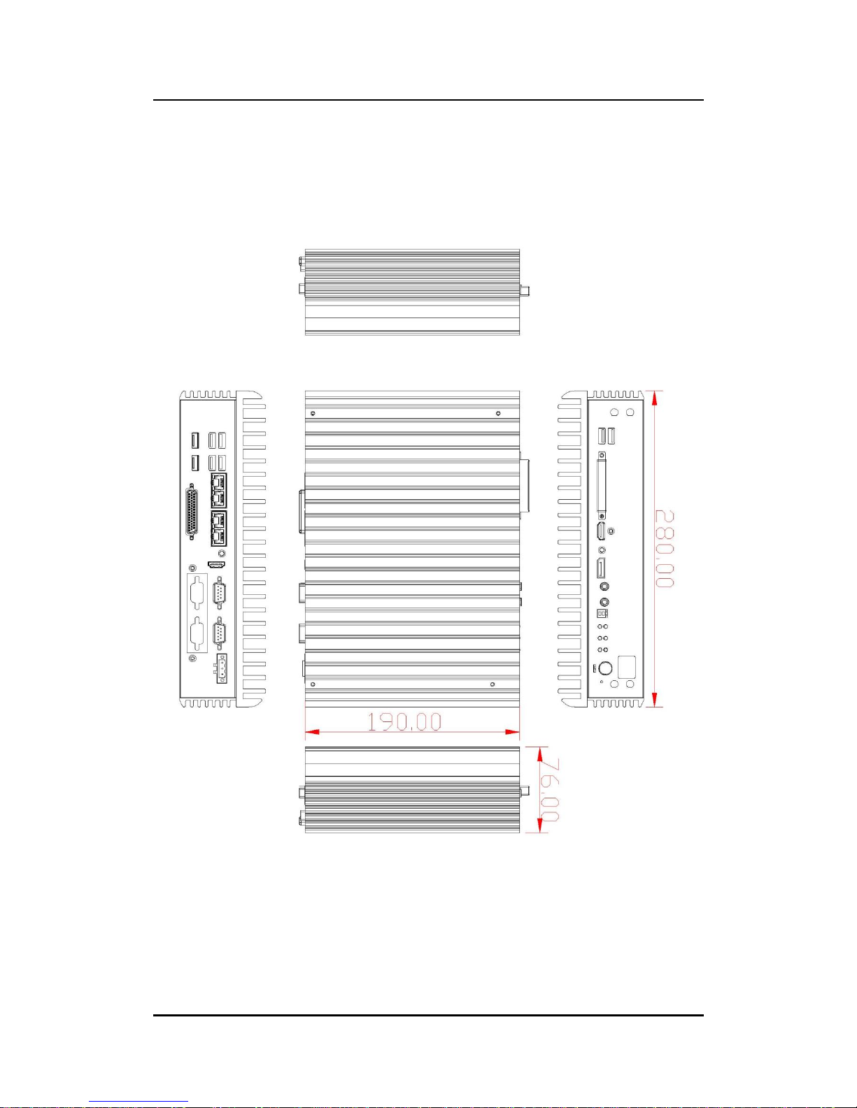
1.3 Dimensions
The following diagrams show dimensions and outlines of the eBOX670-891-FL.
1.3.1 System Dimensions
Page 14
eBOX670-891-FL Series user’s Manual
Introduction
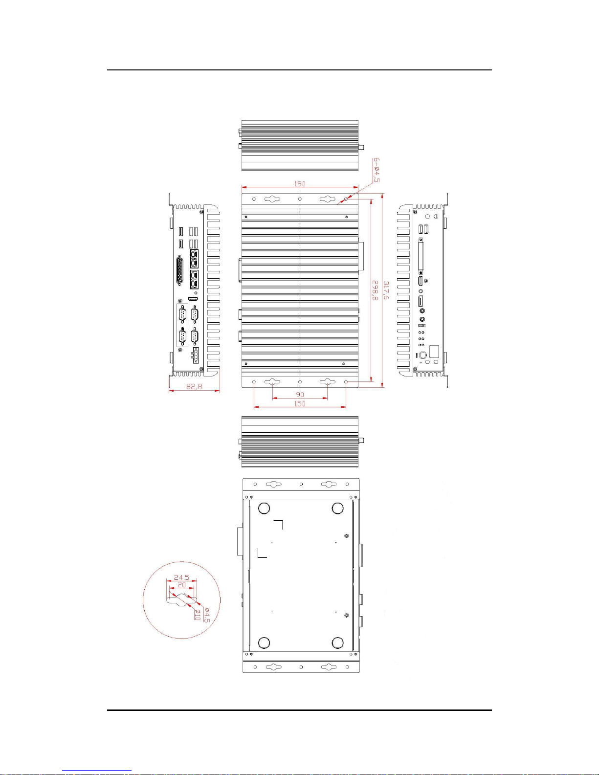
6
1.3.2 Wall-mount Bracket Dimensions
Page 15

eBOX670-891-FL Series user’s Manual
Introduction
7
1.4 I/O Outlets
The following figures show I/O outlets on the eBOX670-891-FL.
Front View
Rear View
Page 16

eBOX670-891-FL Series user’s Manual
Introduction
8
1.5 Packing List
The eBOX670-891-FL comes with the following bundle package:
eBOX670-891-FL System Unit x 1
Quick Installation Guide x 1
DVD x 1 (For Driver and Manual)
CPU Thermal Pad x 1
HDD screws x 8
Terminal Block x 1
Remote switch cable x 1
HDD Bracket x 2
1.6 Model List
eBOX670-891-FL-DC
Fanless embedded system with LGA1151 socket 6th
generation Intel® Core™ i7/i5/i3 & Celeron® processors, Intel®
Q170 chipset, 2 HDMI, 1 DisplayPort, 4 GbE LANs, 6 USB
3.0, CFast™, dual PCI Express Mini Card slots
Please contact Axiomtek’s distributors immediately in case any abovementioned items are
missing.
Page 17
eBOX670-891-FL Series user’s Manual
Hardware Installation
9
SECTION 2
HARDWARE INSTALLATION
The eBOX670-891-FL is convenient for various hardware configurations, such as CPU,
DRAM, HDD (Hard Disk Drive), SSD (Solid State Drive), CFastTM card and PCI Express Mini
card modules. Section 2 contains guidelines for hardware installation.
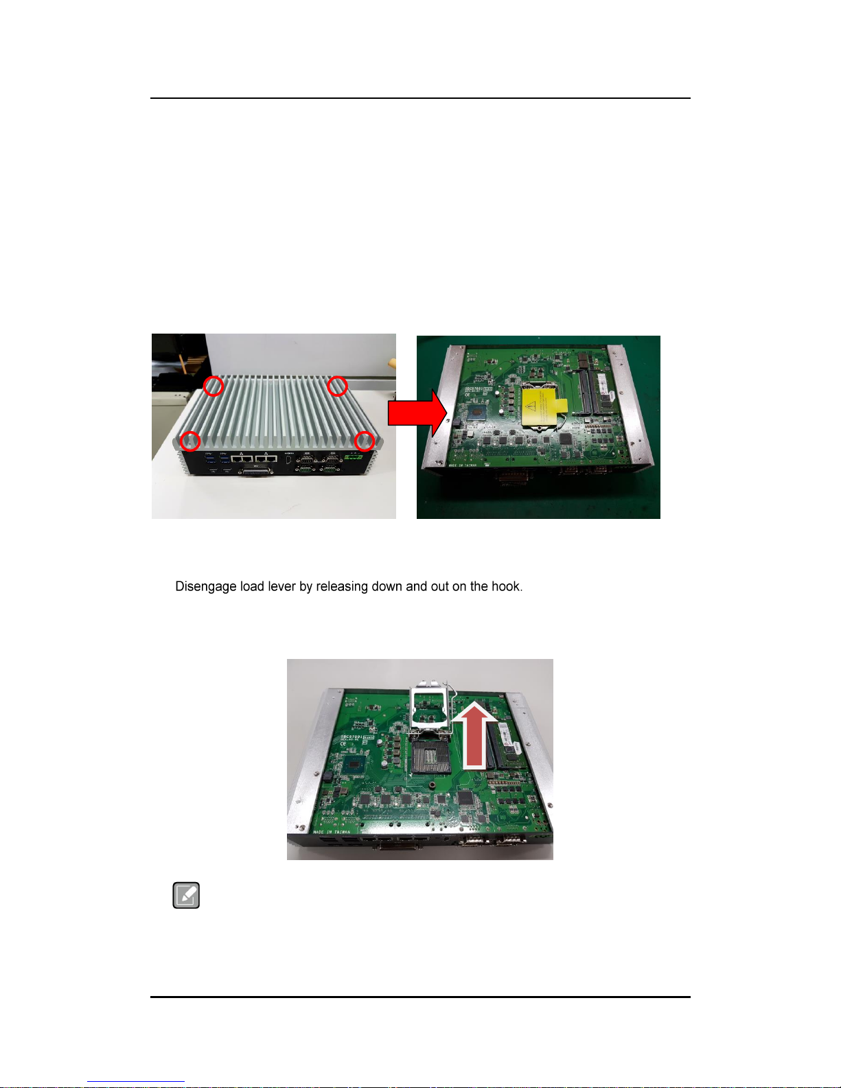
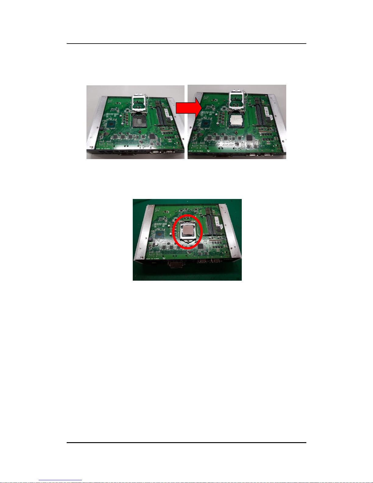
2.1 Installation of CPU
Step 1 Turn off the system and unplug the power cord.
Step 2 Loosen all screws to remove top cover.
Step 3 Remove the warning label and disengage load lever.
Rotate load lever to open position at approximately 135°.
Rotate load plate to open position at approximately 150°.
Note
Apply pressure to corner with right-hand thumb when opening or
closing load lever - otherwise lever will bounce back (as a mouse trap)
causing bent contacts.
Page 18
eBOX670-891-FL Series user’s Manual
Hardware Installation
10
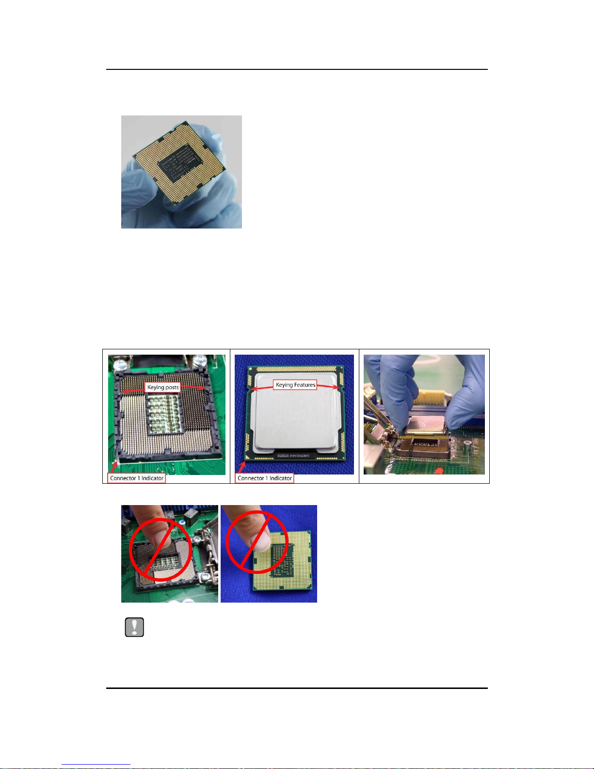
Step 4 CPU installation steps:
Lift processor package from shipping media by grasping the substrate edges.
Scan the processor package gold pads for any presence of foreign material.
Locate connection 1 indicator on the processor which aligns with connection 1 indicator
chamfer on the socket, and notice processor keying features that line up with posts along
socket walls.
Grasp the processor with thumb and index finger along the top and bottom edges.
The socket will have cutouts for your fingers to fit into.
Carefully place the processor into the socket body vertically.
Caution
Never touch fragile socket contacts to avoid damage and do not touch processor
sensitive contacts at any time during installation.
Page 19
eBOX670-891-FL Series user’s Manual
Hardware Installation
11
Step 5 Align pins of the CPU with pin holes of the socket. Be careful of the
CPU’s orientation that user’ s need to align the arrow mark on the CPU
with the arrow key on the socket.
Step 6 Paste the thermal pad on top of the processor with caution, and then
remove protection film.
Step 7 Put the top cover and fasten four screws back onto the system.
Page 20
eBOX670-891-FL Series user’s Manual
Hardware Installation
12
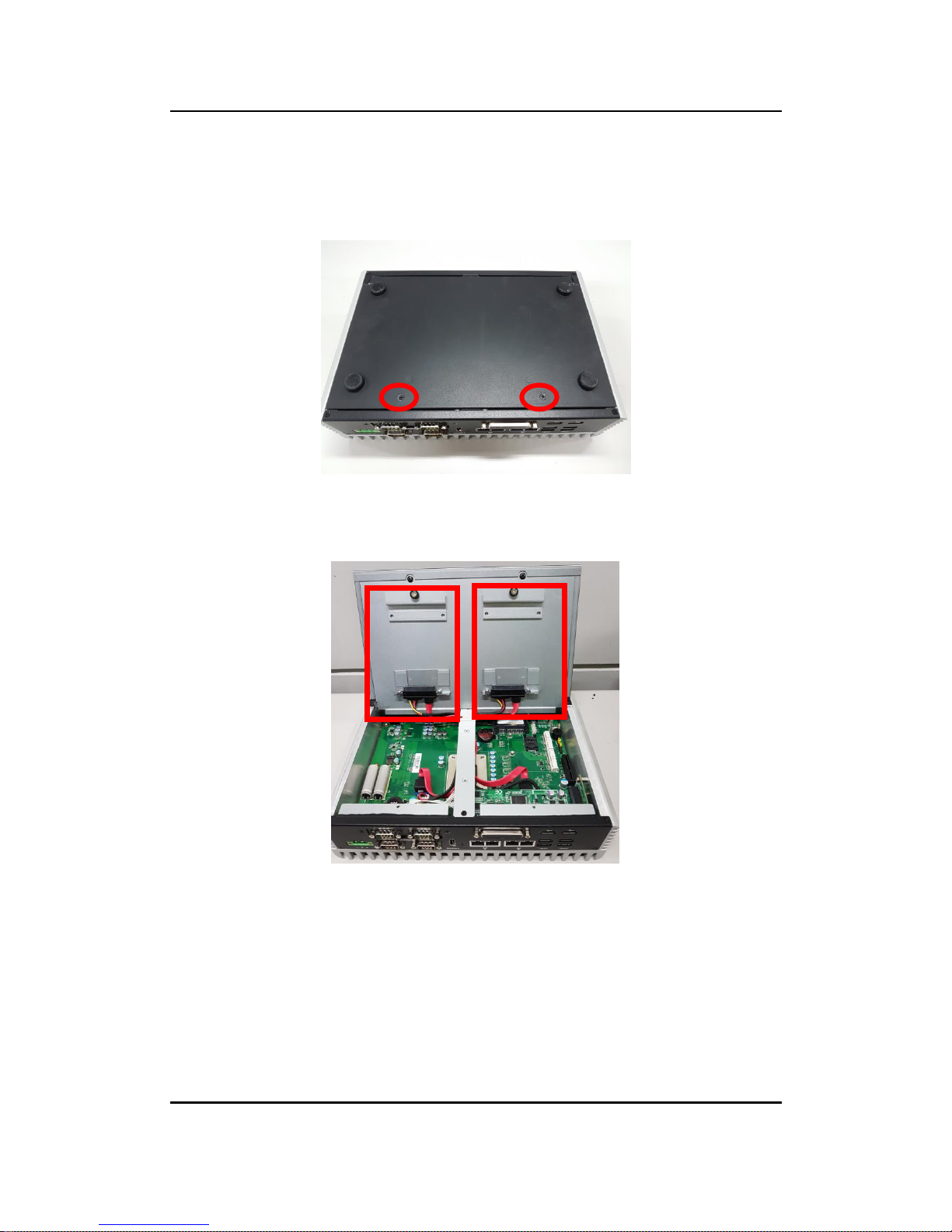
2.2 Installation of 2.5" SATA Device
Step 1 Turn off the system and unplug the power cord.
Step 2 Turn the system upside down to locate screws at the bottom and then
loosen all screws.
Step 3 Open the bottom cover.
Step 4 Locate SSD /HDD within the red line as marked.
Please notice the direction of connector for HDD.
Page 21
eBOX670-891-FL Series user’s Manual
Hardware Installation
13
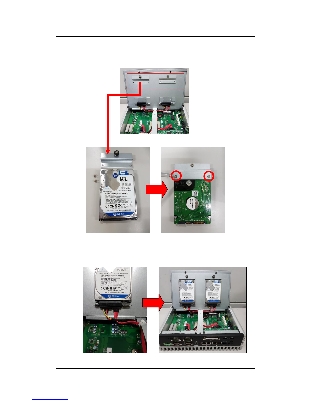
Step 5 Before assemble the SSD/HDD, please loosen the thumb screws to
remove two HDD brackets, and then assemble the SSD/HDD with the
two HDD mounting screws. Make sure the PCB side of the SSD/HDD
will be facing the bottom cover.
.
Step 6 Connected the SSD/HDD directly and make sure the insertion is
complete.
Page 22
eBOX670-891-FL Series user’s Manual
Hardware Installation
14
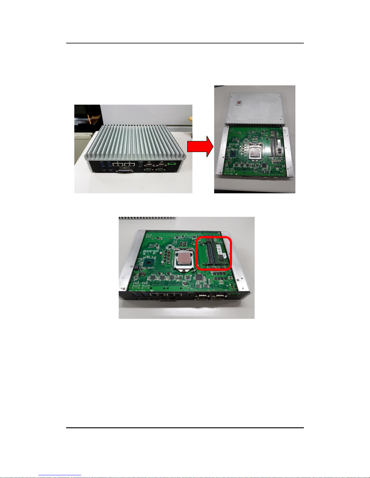
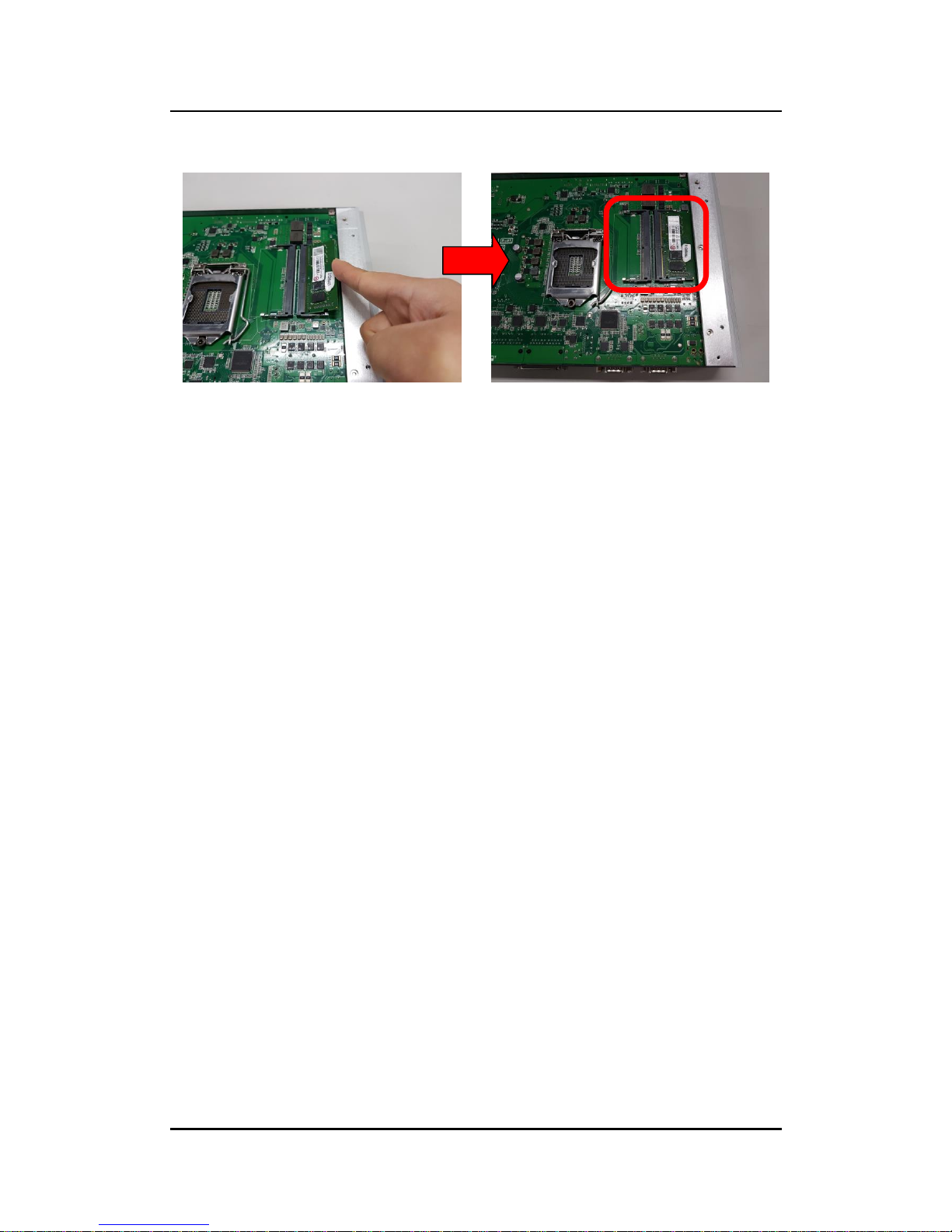
2.3 Installation of SO-DIMM
Step 1 Turn off the system and unplug the power cord.
Step 2 Four screws on the top heatsink are used to fasten the heatsink to the
chassis.
Step 3 Located the dual SO-DIMM sockets on main board.
Page 23
eBOX670-891-FL Series user’s Manual
Hardware Installation
15
Step 4 Locate the memory module, insert a gold colored contact into the
socket and push the module two end latches till locked.
Step 5 Put the top cover and fasten four screws back onto the system.
Page 24
eBOX670-891-FL Series user’s Manual
Hardware Installation
16
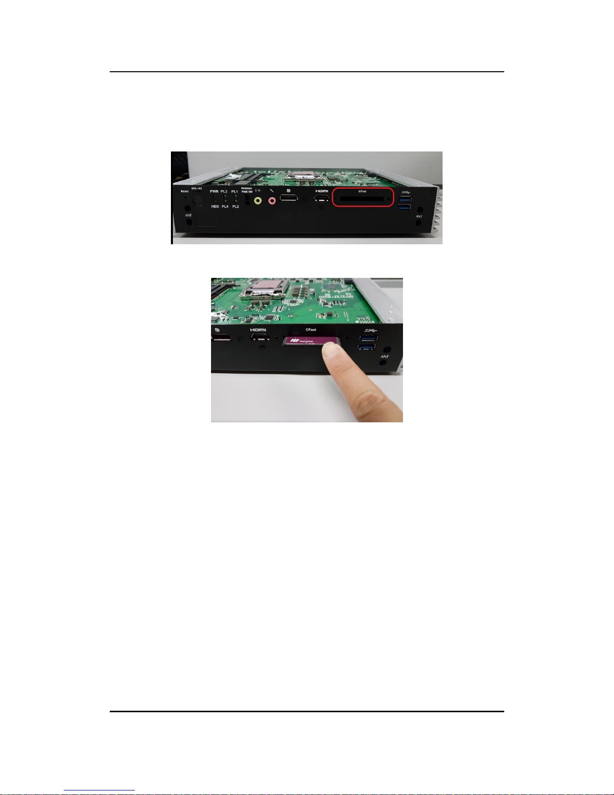
2.4 Installation of CFastTM Module
Step 1 Turn off the system and unplug the power cord.
Step 2 Located the CFastTM slot on front panel.
Step 3 Insert a CFast
TM
module into the socket.
Step 4 Recover and fasten all screws of the top cover.
Page 25
eBOX670-891-FL Series user’s Manual
Hardware Installation
17
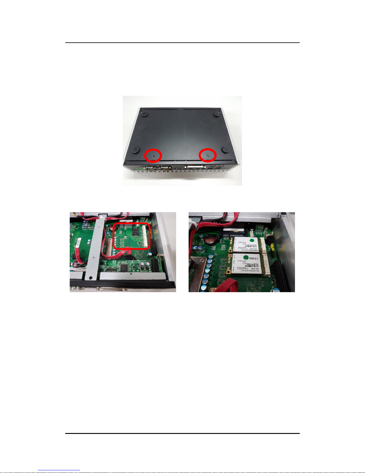
2.5 Installation of Mini PCIe Module (full-size)
Step 1 Turn off the system and unplug the power cord.
Step 2 Turn the system upside down to locate screws at the bottom, and then
loosen all screws.
Step 3 Identify the two full-size mini PCIe slots, insert a mini PCIe module into
the sockets and then fasten all screws.
Step 4 Put the bottom cover and fasten two screws back onto the system.
Page 26
eBOX670-891-FL Series user’s Manual
Hardware Installation
18
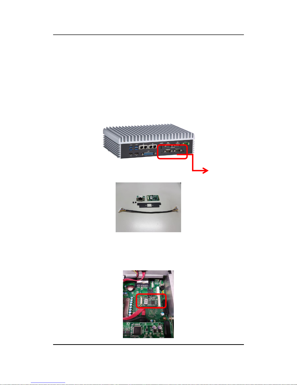
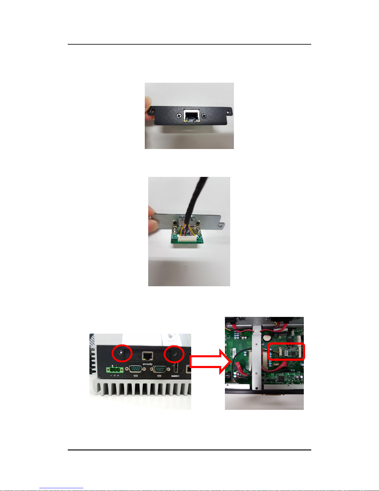
2.6 Installation of Flexible I/O Modules
The eBOX670-891 provides an optional window for customer add flexible I/O
modules, according to different modules , please refer to quick manual
-LAN Module (RJ45*1)
-DIO Module (DB9*1)
-CAN Bus/CAN Open Module (DB9*2)
-USB Module (USB*1)
Steps 1 Prepare the LAN module kit.
Step 2 Turn off the system and unplug the power cord.
Step 3 Open the bottom cover.
Step 4 Insert the LAN mini PCIe card.
Optional Window
(Default: 2 x COM)
Page 27
eBOX670-891-FL Series user’s Manual
Hardware Installation
19
Step 5 Assemble LAN connector with bracket.
Step 6 Connected the cable with the LAN module.
Step 7 Fasten the LAN bracket into the chassis, and then connect the LAN
cable to the mini PCIe module.
Step 8 Put the bottom cover and fasten two screws back onto the system.
Page 28

eBOX670-891-FL Series user’s Manual
Hardware Installation
20
This page is intentionally left blank.
Page 29

eBOX670-891-FL Series user’s Manual
Jumper & Connector Settings
21
SECTION 3
JUMPER & CONNECTOR SETTINGS
Proper jumper settings configure the eBOX670-891-FL to meet various application needs.
Hereby all jumpers settings along with their default settings are listed for devices onboard.
3.1 Locations of Jumpers & Connectors
SBC87891 Top View
Page 30

eBOX670-891-FL Series user’s Manual
Jumper & Connector Settings
22
SBC87891 Bottom View
【Note】: It is strongly recommended that any unmentioned jumper settings
should not be modified without instructions by Axiomtek FAEs. Any
modifications without instructions might cause system failure.
Page 31

eBOX670-891-FL Series user’s Manual
Jumper & Connector Settings
23
3.2 Summary of Jumper Settings
Proper jumper settings configure the eBOX670-891-FL to meet various application purposes.
A table of all jumpers and their default settings is listed below.
Jumpers
Descriptions
Settings
JP1
Restore BIOS Optimal Defaults
Default: Normal Operation
Short 1-2
【Note】: How to setup Jumpers
That a cap on a jumper is to “close” the jumper, whereas that offs a jumper is to “open” the
jumper.
[Open] [Closed] [Pin1-2 Closed]
3.2.1 Restore BIOS Optimal Defaults (JP1)
Put jumper clip to pin 2-3 for a few seconds then move it back to pin 1-2.
This procedure is to restore BIOS optimal defaults.
Functions
Settings
Normal (Default)
1-2
Clear RTC
2-3
Page 32

eBOX670-891-FL Series user’s Manual
Jumper & Connector Settings
24
3.3 Connectors
Please refer to pin assignments below:
External Connectors
Sections
DC-in Phoenix Power Connector
3.3.1
HDMI Connector
3.3.2
DisplayPort Connector
3.3.3
Serial Port Connector
3.3.4
USB 3.0 Connector
3.3.5
Ethernet Connector
3.3.6
USB 2.0 Connector
3.3.7
Audio Connector
3.3.8
Digital I/O Connector
3.3.9
ATX Power On/Off Button
3.3.10
Rest Button
3.3.11
Remote Power Switch Connector
3.3.12
AT/ATX Switch
3.3.13
CFastTM Socket
3.3.14
Internal Connectors
Sections
Serial ATA (SATA) Connector
3.3.15
SATA Power Connector
3.3.16
SIM Card Slot (SCN1)
3.3.17
Full-Size Express Mini Card slot (SCN2 & SCN3)
3.3.18
Page 33

eBOX670-891-FL Series user’s Manual
Jumper & Connector Settings
25
3.3.1 DC-in Phoenix Power Connector
The system supports 9~36V Phoenix DC-in connector for system power input.
Pins
Signals
1
DC+
2
GND
3
DC-
3.3.2 HDMI Connector
The HDMI (High-Definition Multimedia Interface) is a compact digital interface which
is capable of transmitting high-definition video and high-resolution audio over a
single cable.
Pins
Signals
Pins
Signals
HDMI2.0
HDMI1.4b
1
HDMI OUT_DATA2+
11
GND
2
GND
12
HDMI OUT Clock-
3
HDMI OUT_DATA2-
13
N.C.
4
HDMI OUT_DATA1+
14
N.C.
5
GND
15
HDMI OUT_SCL
6
HDMI OUT_DATA1-
16
HDMI OUT_SDA
7
HDMI OUT_DATA0+
17
GND
8
GND
18
+5V 9 HDMI OUT_DATA0-
19
HDMI_HTPLG
10
HDMI OUT Clock+
Page 34

eBOX670-891-FL Series user’s Manual
Jumper & Connector Settings
26
3.3.3 DisplayPort Connector
Pins
Signals
Pins
Signals
1
DPB_LANE0
11
GND
2
GND
12
DPB_LANE3#
3
DPB_LANE0#
13
Detect Pin
4
DPB_LANE1
14
GND
5
GND
15
DPB_AUX
6
DPB_LANE1#
16
GND
7
DPB_LANE2
17
DPB_AUX#
8
GND
18
DPB_HPDE
9
DPB_LANE2#
19
GND
10
DPB_LANE3
20
+3.3V
3.3.4 Serial Port Connector (COM 1~COM 4)
The system has four serial ports. COM1~COM4 are RS-232/422/485 ports. Please refer to
Chapter 4 for the detail of BIOS setting.
※COM1~4
Pins
RS-232
RS-422
RS-485
1
DCD, Data Carrier Detect
TX-
Data-
2
RXD, Receive Data
TX+
Data+
3
TXD, Transmit Data
RX+
No use
4
DTR, Data Terminal Ready
RX-
No use
5
GND, Ground
No use
No use
6
DSR, Data Set Ready
No use
No use
7
RTS, Request To Send
No use
No use
8
CTS, Clear To Send
No use
No use
9
RI, Ring Indicator
No use
No use
Page 35

eBOX670-891-FL Series user’s Manual
Jumper & Connector Settings
27
3.3.5 USB 3.0 Connector
The Universal Serial Bus connectors are compliant with USB 3.0 (5 GB/s), and
ideally for installing USB peripherals such as scanner, camera and USB devices, etc.
Pins
Signal USB Port 0
Pins
Signal USB Port 1
1
USB_VCC (+5V level
standby power)
10
USB_VCC (+5V level standby
power)
2
USB_Data-
11
USB_Data-
3
USB_Data+
12
USB_Data+
4
GND
13
GND
5
SSRX-
14
SSRX-
6
SSRX+
15
SSRX+
7
GND
16
GND
8
SSTX-
17
SSTX-
9
SSTX+
18
SSTX+
3.3.6 Ethernet Connector (LAN1~LAN4)
The board has four RJ-45 connectors are for LAN1 Ethernet-(Intel i219LM)
LAN2-4 Ethernet-(Intel i210-iT).
L1L2L3L4L5L6L7L8
A B
Pins
LAN Signal
Pins
LAN Signal
L1
MDI0+
L5
MDI2+
L2
MDI0-
L6
MDI2-
L3
MDI1+
L7
MDI3+
L4
MDI1-
L8
MDI3-
A
Activity link LED(Yellow)
OFF: No link
Blinking: Link established; data activity
detected
B
Speed LED
OFF: 10Mbps data rate
Green: 100Mbps data rate
Orange: 1GMbps data rate
Page 36

eBOX670-891-FL Series user’s Manual
Jumper & Connector Settings
28
3.3.7 USB 2.0 Connector
The Universal Serial Bus connectors are compliant with USB 2.0 (480Mbps), and ideally for
installing USB peripherals such as keyboard, mouse, scanner, etc.
3.3.8 Audio Connector
These two audio jacks ideal are for Audio Mic-In and Audio Line-out.
Pins
Signals
1
Line Out
2
Microphone In
Pins
Signal USB Port
1
USB VCC
(+5V level)
2
USB #0_D-
3
USB #0_D+
4
Ground (GND)
Page 37

eBOX670-891-FL Series user’s Manual
Jumper & Connector Settings
29
3.3.9 Digital I/O
The system is equipped with 32bit Programmable Digital I/O for 44-pin D-Sub female
connectors, please refer to the following table to get default pin define. Default is 16in/16out.
The digital I/O can be configured to control cash drawers and sense warning signals from an
Uninterrupted Power System (UPS), or perform store security control. You may use software
programming to control these digital signals.
Pins
Signals
Pins
Signals
1
N/A 2 N/A 3 Din
4
Dout 5 Din
6
Dout 7 Din
8
Dout 9 Din
10
Dout
11
Din
12
Dout
13
Din
14
Dout
15
Din
16
Dout
17
Din
18
Dout
19
Din
20
Dout
21
Din
22
Dout
23
Din
24
Dout
25
Din
26
Dout
27
Din
28
Dout
29
Din
30
Dout
31
Din
32
Dout
33
Din
34
Dout
35
GND
36
GND
37
N/A
38
N/A
39
N/A
40
N/A
41
N/A
42
N/A
43
N/A
44
N/A
Page 38

eBOX670-891-FL Series user’s Manual
Jumper & Connector Settings
30
3.3.10 ATX Power On/OFF
The ATX power button is on the I/O side. It can allow users to control eBOX670-891-FL power
on/off.
Functions
Descriptions
On
Turn on/off system
Off
Keep system status
3.3.11 Reset Button
The Reset button can allow users to reset eBOX670-891-FL.
Functions
Descriptions
On
Reset system
Off
Keep system status
3.3.12 Remote Power Switch Connector
One 2-pin connector output for remote power on/off switch.
Functions
Descriptions
Short(1-2)
Turn on/off system
Open
Keep system status
3.3.13 AT/ATX Switch
If you set AT/ATX switch to AT mode, the system will be automatically power on without
pressing soft power button during power input; we can use this switch to achieve auto power
on demand.
Page 39

eBOX670-891-FL Series user’s Manual
Jumper & Connector Settings
31
3.3.14 CFast™ Socket
The system is equipped with a CFast™ socket on the bottom side to support a CFast™ card
which is based on the Serial ATA bus. The socket is specially designed to avoid incorrect
installation of the CFast™ card. When installing or removing the CFast™ card, please make
sure the system power is off. The CFast™ card by default identifies itself as C: or D: drive in
your PC system.
Pins
Signals
Pins
Signals
S1
GND
PC1
NC
S2
TX+
PC2
GND
S3
TX-
PC3
NC
S4
GND
PC4
NC
S5
RX-
PC5
NC
S6
RX+
PC6
NC
S7
GND
PC7
GND
PC8
NC
PC9
NC
PC10
NC
PC11
NC
PC12
NC
PC13
3.3V
PC14
3.3V
PC15
GND
PC16
GND
PC17
NC
Page 40

eBOX670-891-FL Series user’s Manual
Jumper & Connector Settings
32
3.3.15 SATA Connector (SATA 1 & 2)
These Serial Advanced Technology Attachment (Serial ATA or SATA) connectors are for
high-speed SATA interfaces. They are computer bus interfaces for connecting to devices such
as hard disk drives. This board has two SATA 3.0 ports with 6Gb/s performance.
3.3.16 SATA Power Connector
Use CN8、CN9 for interfacing to SATA 2.5" HDD power supply.
3.3.17 SIM Card Slots (SCN1)
The eBOX670-891-FL includes one SIM slots (SCN1) on the bottom side of the system
for inserting SIM Card. It is mainly used in 3G/LTE wireless network application on
SCN3.
Pins
Signals
1
GND
2
SATA_TX+
3
SATA_TX-
4
GND
5
SATA_RX-
6
SATA_RX+
7
GND
Pins
Signals
1
+12V level
2
GND
3
GND
4
+5V level
Pins
Signals
1
PWR
2
RST
3
CLK
4
NC 5 GND
6
VPP
7
I/O
8
NC
Page 41

eBOX670-891-FL Series user’s Manual
Jumper & Connector Settings
33
3.3.18 Full-Size PCI Express Mini Card Slot (SCN2 & SCN3)
The eBOX670-891-FL supports dual full-size PCI-Express Mini Card slots.SCN2 is applying to
either PCI-Express or USB 2.0 signal, and complies with PCI-Express Mini Card Spec. V1.2.
SCN3 is applying for PCI-Express and SATA (mSATA) signals and complies with PCIExpress Mini Card Spec. V1.2. Thus, users can install mSATA cards into this slot. Please
refer to the SATA of BIOS setting to enable or disable mSATA supported
SCN2
Pins
Signals
Pins
Signals
1
WAKE#
2
+3.3VSB
3
No use
4
GND
5
No use
6
+1.5V
7
CLKREQ#
8
No use
9
GND
10
No use
11
REFCLK-
12
No use
13
REFCLK+
14
No use
15
GND
16
No use
17
No use
18
GND
19
No use
20
W_DISABLE#
21
GND
22
PERST#
23
PE_RXN3/
24
+3.3VSB
25
PE_RXP3/
26
GND
27
GND
28
+1.5V
29
GND
30
SMB_CLK
31
PE_TXN3/
32
SMB_DATA
33
PE_TXP3/
34
GND
35
GND
36
USB_D8-
37
GND
38
USB_D8+
39
+3.3VSB
40
GND
41
+3.3VSB
42
No use
43
GND
44
No use
45
No use
46
No use
47
No use
48
+1.5V
49
No use
50
GND
51
No use
52
+3.3VSB
Page 42

eBOX670-891-FL Series user’s Manual
Jumper & Connector Settings
34
SCN3
Pins
Signals
Pin
Signals
1
WAKE#
2
+3.3VSB
3
No use
4
GND
5
No use
6
+1.5V
7
CLKREQ#
8
No use
9
GND
10
No use
11
REFCLK-
12
No use
13
REFCLK+
14
No use
15
GND
16
No use
17
No use
18
GND
19
No use
20
W_DISABLE#
21
GND
22
PERST#
23
PE_RXN3/mSATA
24
+3.3VSB
25
PE_RXP3/mSATA
26
GND
27
GND
28
+1.5V
29
GND
30
SMB_CLK
31
PE_TXN3/ mSATA
32
SMB_DATA
33
PE_TXP3/ mSATA
34
GND
35
GND
36
USB_D8-
37
GND
38
USB_D8+
39
+3.3VSB
40
GND
41
+3.3VSB
42
No use
43
GND
44
No use
45
No use
46
No use
47
No use
48
+1.5V
49
No use
50
GND
51
No use
52
+3.3VSB
Page 43

eBOX670-891-FL Series user’s Manual
BIOS Setup Utility
35
SECTION 4
BIOS SETUP UTILITY
This section provides users with detailed descriptions in terms of how to set up basic
system configurations through the BIOS setup utility.
4.1 Starting
To enter the setup screens, follow the steps below:
1. Turn on the computer and press the <Del> key immediately.
2. After press the <Del> key, the main BIOS setup menu displays. Users can access to
other setup screens, such as the Advanced and Chipset menus, from the main BIOS
setup menu.
It is strongly recommended that users should avoid changing the chipset’s defaults. Both AMI
and system manufacturer have carefully set up these defaults that provide the best
performance and reliability.
4.2 Navigation Keys
The BIOS setup/utility uses a key-based navigation system called hot keys. Most of the BIOS
setup utility hot keys can be used at any time during the setup navigation process. These keys
include <F1>, <F2>, <Enter>, <ESC>, <Arrow> keys, and so on.
【 Note】: Some of the navigation keys differ from one screen to another.
Hot Keys
Descriptions
Left/Right
The Left and Right <Arrow> keys allow users to select a setup screen.
Up/Down
The Up and Down <Arrow> keys allow users to select a setup screen or
sub-screen.
+ Plus/Minus
The Plus and Minus <Arrow> keys allow users to change the field value of a
particular setup item.
Tab
The <Tab> key allows users to select setup fields.
F1
The <F1> key allows users to display the General Help screen.
F2
The <F2> key allows users to Load Previous Values.
F3
The <F3> key allows users to Load Optimized Defaults.
F4
The <F4> key allows users to save any changes they made and exit the
Setup. Press the <F4> key to save any changes.
Esc
The <Esc> key allows users to discard any changes they made and exit the
Setup. Press the <Esc> key to exit the setup without saving any changes.
Enter
The <Enter> key allows users to display or change the setup option listed
for a particular setup item. The <Enter> key can also allow users to display
the setup sub- screens.
Page 44

eBOX670-891-FL Series user’s Manual
BIOS Setup Utility
36
4.3 Main Menu
The Main Menu screen is the first screen users see when entering the setup utility. Users can
always return to the Main setup screen by selecting the Main tab. System Time/Date can be
set up as described below. The Main BIOS setup screen is also shown below.
BIOS Information
Display the auto-detected BIOS information.
System Language
Choose the system default language.
System Date/Time
Use this option to change the system time and date. Highlight System Time or System Date
using the <Arrow> keys. Enter new values through the keyboard. Press the <Tab> key or the
<Arrow> keys to move between fields. The date must be entered in MM/DD/YY format. The
time is entered in HH:MM:SS format.
Access Level
Display the access level of current user.
Page 45

eBOX670-891-FL Series user’s Manual
BIOS Setup Utility
37
4.4 Advanced Menu
The Advanced menu also allows users to set configuration of the CPU and other system
devices. Users can select any items in the left frame of the screen to go to sub menus:
► Mini Card Switch
► ACPI Settings
► CPU Configurations
► SATA Configurations
► PCH-FW Configurations
► AMT Configurations
► USB Computing
► NCT6102D Super IO Configurations
► NCT6106DSEC Super IO Configurations
► Hardware Monitor
► Utility Configurations
For items marked with “”, please press <Enter> for more options.
Page 46

eBOX670-891-FL Series user’s Manual
BIOS Setup Utility
38
Mini Card Switch
Use this to select Mini Card setting, default is “PCIE”.
Page 47

eBOX670-891-FL Series user’s Manual
BIOS Setup Utility
39
ACPI Settings
Use this screen to select options for the ACPI configuration, and change the value of the
selected option. A description of the selected item appears on the right side of the screen.
ACPI Sleep State
When the sleep button is pressed, the system will be in the ACPI sleep state.
The default is S3 (Suspend to RAM).
Page 48

eBOX670-891-FL Series user’s Manual
BIOS Setup Utility
40
CPU Configurations
This screen shows the CPU version and its detailed information.
Intel Virtualization Technology
It allows a hardware platform to run multiple operating systems separately and simultaneously,
enabling one system to virtually function as several systems.
Page 49

eBOX670-891-FL Series user’s Manual
BIOS Setup Utility
41
SATA Configurations
In this Configuration menu, you can see the currently installed hardware in the SATA ports.
During system boot up, the BIOS automatically detects the presence of SATA devices.
Page 50

eBOX670-891-FL Series user’s Manual
BIOS Setup Utility
42
SATA Mode Selection
AHCI (Advanced Host Controller Interface) mode is how SATA controller(s) operate.
Serial ATA Port 0~3
It shows the device installed in connector SATA0~3
Page 51

eBOX670-891-FL Series user’s Manual
BIOS Setup Utility
43
PCH-FW Configuration
This screen shows ME Firmware information.
Page 52

eBOX670-891-FL Series user’s Manual
BIOS Setup Utility
44
AMT Configurations
User can use this screen to configure AMT parameters.
Intel AMT
Enable or disable Intel
®
Active Management Technology BIOS Extension.
The default is enabled.
Page 53

eBOX670-891-FL Series user’s Manual
BIOS Setup Utility
45
USB Configurations
USB Devices
Display all detected USB devices.
Page 54

eBOX670-891-FL Series user’s Manual
BIOS Setup Utility
46
NCT6102D Super IO Configurations
Use this screen to select options for the NCT6102D Super IO Configurations, and change the
value of the selected option. A description of the selected item appears on the right side of the
screen. For items marked with , please press <Enter> for more options
Serial Port 1~2 (COM1~2) Configurations
Use these items to set parameters related to serial ports 1~2.
Page 55

eBOX670-891-FL Series user’s Manual
BIOS Setup Utility
47
Serial Port 1
Select Mode
Use this option to set RS-232/RS-422/RS-485 mode.
Serial Port 2
Page 56

eBOX670-891-FL Series user’s Manual
BIOS Setup Utility
48
NCT6102DSEC Super IO Configurations
Use this screen to select options for the NCT6106DSEC super IO Configurations, and change
the value of the selected option. A description of the selected item appears on the right side of
the screen. For items marked with , please press <Enter> for more options
Page 57

eBOX670-891-FL Series user’s Manual
BIOS Setup Utility
49
Page 58

eBOX670-891-FL Series user’s Manual
BIOS Setup Utility
50
Hardware Monitor
This screen monitors hardware health status.
This screen displays the temperature of system and CPU, system voltages (VCORE, +3.3V,
+12V and +5V).
Page 59

eBOX670-891-FL Series user’s Manual
BIOS Setup Utility
51
Utility Configurations
This screen is for BIOS flash utility.
BIOS Flash Utility
BIOS flash utility configuration.
Page 60

eBOX670-891-FL Series user’s Manual
BIOS Setup Utility
52
USB Configurations
This screen specifies USB settings.
USB Devices
Display all detected USB devices.
Legacy USB Support
Use this item to enable or disable support for USB device on legacy operating system. The
default setting is Enabled. Auto option disables legacy support if no USB devices are
connected, Disable option will keep USB devices available only for EFI applications.
Page 61

eBOX670-891-FL Series user’s Manual
BIOS Setup Utility
53
4.5 Chipset Menu
The Chipset menu allows users to change the advanced chipset settings. Users can select
any of the items in the left frame of the screen to go to the sub menus:
► System Agent (SA) Configurations
► PCH-IO Configurations
For items marked with “”, please press <Enter> for more options.
Page 62

eBOX670-891-FL Series user’s Manual
BIOS Setup Utility
54
System Agent (SA) Configurations
Graphics Configuration
Use this item to configure internal graphics controller.
Memory Configuration
Use this item to refer to the information related to system memory.
Page 63

eBOX670-891-FL Series user’s Manual
BIOS Setup Utility
55
Graphic Configurations
Primary IGFX Boot Display
Select the video device which will be activated during POST (Power-On Self-Test).
The default is HDMI (ONBOARD).The image above shows option list in Primary IGFX Boot
Display when no I/O board is installed.
Page 64

eBOX670-891-FL Series user’s Manual
BIOS Setup Utility
56
Memory Configurations
This screen shows the system memory information.
PCH-IO Configurations
This screen allows users to set PCH parameters.
Page 65

eBOX670-891-FL Series user’s Manual
BIOS Setup Utility
57
Security Menu
Administrator Password
This item indicates whether an administrator password has been set (installed or uninstalled).
User Password
This item indicates whether a user password has been set (installed or uninstalled).
Page 66

eBOX670-891-FL Series user’s Manual
BIOS Setup Utility
58
4.6 Boot Menu
The Boot menu allows users to change boot options of the system.
Setup Prompt Timeout
Use this item to set up number of seconds to wait for setup activation key where
65535(0xFFFF) means indefinite waiting.
Bootup NumLock State
Use this item to select the power-on state for the keyboard NumLock.
Quiet Boot
Select to display either POST output messages or a splash screen during boot-up.
Legacy PXE OpROM
Use this item to enable or disable the boot ROM function of the onboard LAN chip when the
system boots up.
Vedio
Control the execution of UEFI and legacy video OpROM
Boot Option Priorities
These are settings for boot priority. Specify the boot device priority sequence from the
available devices.
Page 67

eBOX670-891-FL Series user’s Manual
BIOS Setup Utility
59
4.7 Save & Exit Menu
The Save & Exit menu allows users to load system configurations with optimal or fail-safe
default values.
Save Changes and Exit
When users have completed the system configuration changes, select this option to leave
Setup and return to Main Menu. Select Save Changes and Exit from the Save & Exit menu
and press <Enter>. Select Yes to save changes and exit.
Discard Changes and Exit
Select this option to quit Setup without making any permanent changes to the system
configurations and return to Main Menu. Select Discard Changes and Exit from the Save &
Exit menu and press <Enter>. Select Yes to discard changes and exit.
Save Changes and Reset
When completed the system configuration changes, select this option to leave Setup and
reboot the computer so the new system configurations take effect. Select Save Changes and
Reset from the Save & Exit menu and press <Enter>. Select Yes to save changes and reset.
Discard Changes and Reset
Select this option to quit Setup without making any permanent changes to the system
configuration and reboot the computer. Select Discard Changes and Reset from the Save &
Exit menu and press <Enter>. Select Yes to discard changes and reset.
Page 68

eBOX670-891-FL Series user’s Manual
BIOS Setup Utility
60
Save Changes
When completed the system configuration changes, select this option to save changes. Select
Save Changes from the Save & Exit menu and press <Enter>. Select Yes to save changes.
Discard Changes
Select this option to quit Setup without making any permanent changes to the system
configurations. Select Discard Changes from the Save & Exit menu and press <Enter>. Select
Yes to discard changes.
Restore Defaults
It automatically sets all Setup options to a complete set of default settings when users select
this option. Select Restore Defaults from the Save & Exit menu and press <Enter>.
Save as User Defaults
Select this option to save system configuration changes done so far as User Defaults. Select
Save as User Defaults from the Save & Exit menu and press <Enter>.
Restore User Defaults
It automatically sets all Setup options to a complete set of User Defaults when users select
this option. Select Restore User Defaults from the Save & Exit menu and press <Enter>.
Boot Override
Select a drive to immediately boot that device regardless of the current boot order.
Page 69

eBOX670-891-FL Series user’s Manual
Watchdog Timer
61
APPENDIX A
WATCHDOG TIMER
About Watchdog Timer
Software stability is major issue in most applications. Some embedded systems are not
watched by human for 24 hours. It is usually too slow to wait for someone to reboot when
computer hangs. The systems need to be able to reset automatically when things go wrong.
The watchdog timer gives us solutions in this regard.
The watchdog timer is a counter that triggers a system to reset when it counts down to zero
from a preset value. The software starts the counter with an initial value and must reset it
periodically. If the counter ever reaches zero, it means the software has crashed, the system
will reboot.
Page 70

eBOX670-891-FL Series user’s Manual
Watchdog Timer
62
Sample Program
The following example enables configurations using debug tool.
Enable WDT
Enable configuration:
O 2E 87; Un-lock super I/O
O 2E 87
Select logic device:
O 2E 07
O 2F 08
WDT device enable:
O 2E 30
O 2F 01
Set timer unit:
O 2E F0
O 2F 00 ; (00: Sec; 08:Minute)
Set base timer:
O 2E F1
O 2F 0A; Set reset time (where 0A (hex) = 10sec)
Disable WDT
Enable configuration:
O 2E 87; Un-lock super I/O
O 2E 87
Select logic device:
O 2E 07
O 2F 08
WDT device disable:
O 2E 30
O 2F 00
Page 71

eBOX670-891-FL Series user’s Manual
Programmable LED
63
APPENDIX B
PROGRAMMABLE LED
About Programmable
LED eBOX670-891-FL supports four programmable LED which allows user to program the
LED status. It can do as special indicator or alarm. Please refer to Driver CD for sample code
and demo tool.
Page 72

eBOX670-891-FL Series user’s Manual
Programmable LED
64
This page is intentionally left blank.
Page 73

eBOX670-891-FL Series user’s Manual
Programmable Digital I/O
65
APPENDIX C
PROGRAMMABLE DIGITAL I/O
About Programmable Digital I/O
LED eBOX670-891-FL supports 32 channels programmable digital I/O which allows user to
program the DI or DO. Please refer to Driver CD for sample code and demo tool.
Page 74

eBOX670-891-FL Series user’s Manual
Programmable Digital I/O
66
This page is intentionally left blank.
Page 75

eBOX670-891-FL Series user’s Manual
Configuration SATA For RAID
67
APPENDIX D
CONFIGURING SATA FOR RAID
D.1 Configuring SATA Hard Drive(s) for RAID
(Controller: Intel® Q170)
Before you begin the SATA configuration, please prepare:
Two SATA hard drives (to ensure optimal performance, it is recommended that you use
two hard drives with identical model and capacity). If you do not want to create RAID with
the SATA controller, you may prepare only one hard drive.
Please follow up the steps below to configure SATA hard drive(s):
1. Install SATA hard drive(s) in your system.
2. Enter the BIOS Setup to configure SATA controller mode and boot sequence.
3. Configure RAID by the RAID BIOS.
1. Installing SATA hard drive(s) in your system.
Connect one end of the SATA signal cable to the rear of the SATA hard drive, and the other
end to available SATA port(s) on the board. Then, connect the power connector of power
supply to the hard drive.
2. Configuring SATA controller mode and boot sequence by the BIOS Setup.
You have to make sure whether the SATA controller is configured correctly by system BIOS
Setup and set up BIOS boot sequence for the SATA hard drive(s).
Page 76

eBOX670-891-FL Series user’s Manual
Configuring SATA for RAID
68
2.1. Turn on your system, and then press the <Del> button to enter BIOS Setup during running
POST (Power-On Self-Test). If you want to create RAID, just go to the Advanced Settings
menu\SATA Configuration, select the “SATA Mode Selection”, and press <Enter> for
more options.
A list of options appears, please select “RAID”.
2.2. Save and exit the BIOS Setup.
Page 77

eBOX670-891-FL Series user’s Manual
Configuration SATA For RAID
69
3. Configuring RAID by the RAID BIOS.
Enter the RAID BIOS setup utility to configure a RAID array. Skip this step and proceed if you
do not want to create a RAID.
3.1. After the POST memory testing and before the operating system booting, a message
"Press <Ctrl-I> to enter Configuration Utility" shows up, accordingly, press <Ctrl + I> to
enter the RAID BIOS setup utility.
3.2. After you press <Ctrl + I>, the Create RAID Volume screen will appear. If you want to
create a RAID array, select the Create RAID Volume option in the Main Menu and press
<Enter>.
Page 78

eBOX670-891-FL Series user’s Manual
Configuring SATA for RAID
70
3.3. After entering the Create Volume Menu screen, you can type the disk array name with
1~16 letters (letters cannot be special characters) in the item “Name”.
3.4. When finished, press <Enter> to select a RAID level. There are three RAID levels: RAID0,
RAID1 and RAID5 and RAID10. Select a RAID level and press <Enter>.
Page 79

eBOX670-891-FL Series user’s Manual
Configuration SATA For RAID
71
3.5. Set the stripe block size. The KB is the standard unit of stripe block size. The stripe block
size can be 4KB to 128KB. After the setting, press <Enter> for the array capacity.
3.6. After setting all the items on the menu, select Create Volume and press <Enter> to start
creating the RAID array.
Page 80

eBOX670-891-FL Series user’s Manual
Configuring SATA for RAID
72
3.7. When prompting the confirmation, press <Y> to create this volume, or <N> to cancel the
creation.
After the creation is completed, you can see detailed information about the RAID Array in the
Disk/Volume Information section, including RAID mode, disk block size, disk name, and disk
capacity, etc.
Page 81

eBOX670-891-FL Series user’s Manual
Configuration SATA For RAID
73
Delete RAID volume
If you want to delete a RAID volume, select the Delete RAID Volume option in Main Menu.
Press <Enter> and follow on-screen instructions.
Please press <Esc> to exit the RAID BIOS utility. Now, you can proceed to install a SATA
driver controller and the operating system.
Page 82

eBOX670-891-FL Series user’s Manual
Configuring SATA for RAID
74
This page is intentionally left blank.
Page 83

eBOX670-891-FL Series user’s Manual
iAMT Settings
75
APPENDIX E
iAMT SETTINGS
The Intel® Active Management Technology (Intel® iAMT) has decreased a major barrier to IT
efficiency that uses built-in platform capabilities and popular third-party management and
security applications to allow IT a better discovering, healing, and protection their networked
computing assets.
In order to utilize Intel® iAMT you must enter the ME BIOS (<Ctrl + P> during system startup),
change the ME BIOS password, and then select “Intel® iAMT” as the manageability feature.
E.1 Entering MEBx
1. You must go to BIOS to enable iAMT function.
2. Exit from BIOS after starting iAMT, and press <Ctrl + P> to enter MEBx Setting.
**It is better to press <Ctrl + P> before the screen popping out.
E.2 Set and Change Password
1. User will be asked to set a password when first log in. The default password is “admin”.
2. User will be asked to change the password before setting ME.
Page 84

eBOX670-891-FL Series user’s Manual
iAMT Settings
76
3. User must confirm the new password while revising. The new password must contain:
(example: !!11qqQQ) (default value).
Eight characters
One upper case
One lower case
One number
One special symbol, such as ! 、 $ or ; , (、 " , excepted)
Underline ( _ ) and space are valid characters for password, but they won’t make higher
complexity.
Page 85

eBOX670-891-FL Series user’s Manual
iAMT Settings
77
E.3 iAMT Settings
Select Intel® iAMT configuration and press <Enter>.
1. Select Network Setup to configure iAMT.
Page 86

eBOX670-891-FL Series user’s Manual
iAMT Settings
78
2. Select TCP/IP to get into Network interface and set it to Enabled. Get into DHCP Mode
and set it to Disabled.
Page 87

eBOX670-891-FL Series user’s Manual
iAMT Settings
79
3. If DHCP Mode is disabled, set the following settings:
IP address
Subnet mask
4. Go back to Intel
®
iAMT Configuration, then select Activate Network Access and press
<Enter>.
5. Exit from MEBx after completing the iAMT settings.
Page 88

eBOX670-891-FL Series user’s Manual
iAMT Settings
80
E.4 iAMT Web Console
1. From a web browser, please type http://( IP ADDRESS):16992, which connects to iAMT
Web.
Example: http://10.1.40.214:16992
2. To log on, you will be required to type in username and password for access to the Web.
USER: admin (default value)
PASS: (MEBx password)
Page 89

eBOX670-891-FL Series user’s Manual
iAMT Settings
81
3. Enter the iAMT Web.
4. Click Remote Control, and select commands on the right side.
5. When you have finished using the iAMT Web console, close the Web browser.
Page 90

eBOX670-891-FL Series user’s Manual
iAMT Settings
82
This page is intentionally left blank.
 Loading...