

Page 1

eBOX532-100-FL Series
Fanless Embedded System
User’s Manual
Page 2

ii
Disclaimers
This manual has been carefully checked and believed to contain accurate information.
Axiomtek Co., Ltd. assumes no responsibility for any infringements of patents or any third
party’s rights, and any liability arising from such use.
Axiomtek does not warrant or assume any legal liability or responsibility for the accuracy,
completeness or usefulness of any information in this document. Axiomtek does not make
any commitment to update the information in this manual.
Axiomtek reserves the right to change or revise this document and/or product at any time
without notice.
No part of this document may be reproduced, stored in a retrieval system, or transmitted, in
any form or by any means, electronic, mechanical, photocopying, recording, or otherwise,
without the prior written permission of Axiomtek Co., Ltd.
Copyright 2016 Axiomtek Co., Ltd.
All Rights Reserved
Jan. 2016, Version A2
Printed in Taiwan
Page 3

iii
Safety Precautions
Before getting started, please read the following important safety precautions.
1. The eBOX532-100-FL does not come equipped with an operating system. An
operating system must be loaded first before installing any software into the
computer.
2. Be sure to ground yourself to prevent static charge when installing the internal
components. Use a grounding wrist strap and place all electronic components in any
static-shielded devices. Most electronic components are sensitive to static electrical
charge.
3. Disconnect the power cord from the eBOX532-100-FL before making any installation.
Be sure both the system and the external devices are turned OFF. Sudden surge of
power could ruin sensitive components. Make sure the eBOX532-100-FL is properly
grounded.
4. Make sure the voltage of the power source is correct before connecting the
equipment to the power outlet.
5. Turn OFF the system power before cleaning. Clean the system using a cloth only.
Do not spray any liquid cleaner directly onto the screen.
6. Do not leave this equipment in an uncontrolled environment where the storage
temperature is below -20℃ or above 60℃. It may damage the equipment.
7. Do not open the system’s back cover. If opening the cover for maintenance is a must,
only a trained technician is allowed to do so. Integrated circuits on computer boards
are sensitive to static electricity. To avoid damaging chips from electrostatic
discharge, observe the following precautions:
Before handling a board or integrated circuit, touch an unpainted portion of the
system unit chassis for a few seconds. This will help to discharge any static
electricity on your body.
When handling boards and components, wear a wrist-grounding strap, available
from most electronic component stores.
Page 4

iv
Classification
1. Degree of production against electric shock: not classified
2. Degree of protection against the ingress of water: IP40
3. Equipment not suitable for use in the presence of a flammable anesthetic mixture
with air or with oxygen or nitrous oxide.
4. Mode of operation: Continuous
5. Type of protection against electric shock: Class I equipment
General Cleaning Tips
You may need the following precautions before you begin to clean the computer. When you
clean any single part or component for the computer, please read and understand the details
below fully.
When you need to clean the device, please rub it with a piece of dry cloth.
1. Be cautious of the tiny removable components when you use a vacuum cleaner to
absorb the dirt on the floor.
2. Turn the system off before you start to clean up the component or computer.
3. Never drop the components inside the computer or get circuit board damp or wet.
4. Be cautious of all kinds of cleaning solvents or chemicals when you use it for the sake of
cleaning. Some individuals may be allergic to the ingredients.
5. Try not to put any food, drink or cigarette around the computer.
Page 5

v
Cleaning Tools:
Although many companies have created products to help improve the process of cleaning
your computer and peripherals users can also use household items to clean their computers
and peripherals. Below is a listing of items you may need or want to use while cleaning your
computer or computer peripherals.
Keep in mind that some components in your computer may only be able to be cleaned using
a product designed for cleaning that component, if this is the case it will be mentioned in the
cleaning.
Cloth: A piece of cloth is the best tool to use when rubbing up a component. Although
paper towels or tissues can be used on most hardware as well, we still recommend
you to rub it with a piece of cloth.
Water or rubbing alcohol: You may moisten a piece of cloth a bit with some water or
rubbing alcohol and rub it on the computer. Unknown solvents may be harmful to the
plastics parts.
Vacuum cleaner: Absorb the dust, dirt, hair, cigarette particles, and other particles
out of a computer can be one of the best methods of cleaning a computer. Over time
these items can restrict the airflow in a computer and cause circuitry to corrode.
Cotton swabs: Cotton swaps moistened with rubbing alcohol or water are excellent
tools for wiping hard to reach areas in your keyboard, mouse, and other locations.
Foam swabs: Whenever possible it is better to use lint free swabs such as foam
swabs.
Note We strongly recommended that you should shut down the system before you start
to clean any single components.
Please follow the steps below:
1. Close all application programs
2. Close operating software
3. Turn off power switch
4. Remove all device
5. Pull out power cable
Page 6

vi
Scrap Computer Recycling
If the computer equipments need the maintenance or are beyond repair, we strongly
recommended that you should inform your Axiomtek distributor as soon as possible for the
suitable solution. For the computers that are no longer useful or no longer working well,
please contact your Axiomtek distributor for recycling and we will make the proper
arrangement.
Trademarks Acknowledgments
Axiomtek is a trademark of Axiomtek Co., Ltd. IBM, PC/AT, PS/2, VGA are trademarks of
International Business Machines Corporation.
Intel® and Pentium® are registered trademarks of Intel Corporation.
MS-DOS, Microsoft C and QuickBASIC are trademarks of Microsoft Corporation.
VIA is a trademark of VIA Technologies, Inc.
SST is a trademark of Silicon Storage Technology, Inc.
UMC is a trademark of United Microelectronics Corporation.Other brand names and
trademarks are the properties and registered brands of their respective owners.
Page 7

vii
Table of Contents
Disclaimers .............................................................................................................. ii
Safety Precautions ................................................................................................. iii
Classification .......................................................................................................... iv
General Cleaning Tips ........................................................................................... iv
Scrap Computer Recycling .................................................................................... vi
CHAPTER 1 INTRODUCTION ........................................................................ 1
1.1 General Description ............................................................................ 1
1.2 System Specifications ........................................................................ 3
1.2.1 CPU .................................................................................................................... 3
1.2.2 I/O System ......................................................................................................... 3
1.2.3 System Specification ........................................................................................ 4
1.3 Dimensions ......................................................................................... 5
1.4 I/O Outlets ............................................................................................ 7
1.5 Packing List ....................................................................................... 10
CHAPTER 2 HARDWARE INSTALLATION ................................................. 11
2.1 Installing the Memory Module .......................................................... 11
2.2 Installing the Hard Disk Drive .......................................................... 14
2.3 Installing the CompactFlashTM Card ................................................ 16
2.4 Installing DIN Mount (optional) ........................................................ 19
2.5 Installing Rail Mount ................................ ......................................... 21
CHAPTER 3 AMI BIOS Setup Utility ........................................................... 23
3.1 Starting .............................................................................................. 23
3.2 Navigation Keys ................................................................................ 24
3.3 Main Menu ......................................................................................... 25
3.4 Advanced Menu ................................................................................ 26
3.5 Chipset Menu .................................................................................... 33
3.6 Boot Menu ......................................................................................... 40
3.7 Security Menu ................................................................................... 41
3.8 Save & Exit Menu .............................................................................. 42
APPENDIX A Watchdog Timer ................................ ................................ .... 45
About Watchdog Timer .................................................................................... 45
How to Use Watchdog Timer ........................................................................... 45
Sample Program ............................................................................................... 47
Page 8

viii
This page is intentionally left blank.
Page 9

eBOX532-100-FL Series User’s Manual
Introduction
1
CHAPTER 1
INTRODUCTION
This chapter contains general information and detailed specifications of the eBOX532-100-FL.
The Chapter 1 includes the following sections:
General Description
System Specification
Dimensions
I/O Outlets
Package List
1.1 General Description
The eBOX532-100-FL is an embedded system that supports onboard AMD G-Series single
core T40R (1.0 GHz) and Fusion Controller Hub A50M that delivers outstanding system
performance through high-bandwidth interfaces, multiple I/O functions for interactive
applications and various embedded computing solutions, and provide Windows
®
XPE,
Windows® 7, Windows® XP and Linux, suitable for the most endurable operation. It features
fanless design with full feature I/O, has one 204-pin unbuffered SO-DIMM socket for DDR3
1066MHz SO-DIMM memory, maximum memory capacity up to 4GB. It also features one
Gigabit/Fast Ethernet, four USB 2.0 high speed compliant, and built-in high definition audio
codec that can achieve the best stability and reliability for industrial applications. Additionally,
it provides you with unique embedded features, such as two serial ports (2x RS-232) and
enhanced system dependability by built-in Watchdog Timer.
Features
1. Support AMD G-Series APU T40R (1.0GHz)
2. AMD Fusion Controller Hub A50M chipset
3. 1 DDR3 SO-DIMM supports up to 4GB memory capacity
4. 4 USB 2.0 ports
5. 2 COM ports
6. Supports one 10/100/1000Mbps Ethernet port
7. Supports one 2.5” SATA-600 HDD drive bay, one CompactFlash™
8. Watchdog timer
9. Din-rail/desktop/wall mount
Reliable and Stable Design
The eBOX532-100-FL adopts the advanced cooling system and supporting the
CompactFlash™, which makes it especially suitable for vibration environments, best for
industrial automation, digital signage and gaming application.
Page 10
eBOX532-100-FL Series User’s Manual
Introduction
2
O.S. Supported
The eBOX532-100-FL supports Windows® XP, Windows 7 and also supports embedded OS,
such as Windows® XP embedded and Linux. For storage device, the eBOX532-100-FL
supports one 2.5" SATA-600 HDD drive bay, and one type II CompactFlash™ slot.
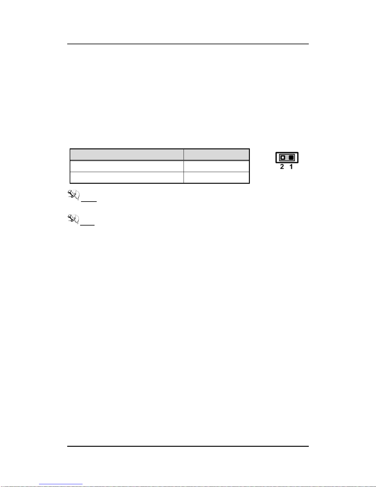
ATX or AT Mode Selection Jumper (JP6)
If JP6 is enabled for power input, the system will be automatically power on without pressing
soft power button. If JP6 is disabled for power input, it is necessary to manually press soft
power button to power on the system.
NOTE This function is similar to the feature of power on after power failure,
which is controlled by hardware circuitry instead of BIOS.
NOTE Once the Jumper is changed to AT model, the system power switch is no
longer usable and system will power-on once DC power enter system.
Therefore, customer needs to have external power switch to switch on/off
the system (because eBOX532’s pow er swi tch i s no longer w orkabl e at AT
mode).
Function
Setting
Disable auto power on (ATX Mode)
1-2 close
Enable auto power on (AT Mode)
1-2 open
Page 11

eBOX532-100-FL Series User’s Manual
Introduction
3
1.2 System Specifications
1.2.1 CPU
CPU
Onboard AMD G-Series APU single core T40R 1.0 GHz.
System Chipset
AMD Fusion Controller Hub A50M.
BIOS
American Megatrends Inc. UEFI (Unified Extensible Firmware Interface)
BIOS
System Memory
One 204-pin unbuffered DDR3 SO-DIMM socket.
Maximum up to 4GB DDR3 1066MHz memory.
1.2.2 I/O System
System I/O Outlet
Two 9-pin D-Sub male connectors, COM1/2 for RS-232
One 15-pin D-Sub female connector for VGA (for eBOX532-100-VGA-FL) or
for DisplayPort (for eBOX532-100-PGA-FL)
One Audio connector (Line-IN, Line-OUT)
One PS/2 connector for Keyboard and M/S through Y-Type cable
One RJ-45 connector for 10/100/1000Base-T Ethernet
Four USB 2.0 connectors
One 5V DC-IN Power Input connector
NOTE DP (DisplayPort) Module
It is used for eBOX532-100-FL1.0G-PGA.
3 types of module are offered by option
- DisplayPort to HDMI Female Cable DP to HDMI
- DisplayPort to DVI Female Cable DP to DVI
- DisplayPort to VGA Female Cable DP to VGA
Page 12

eBOX532-100-FL Series User’s Manual
Introduction
4
1.2.3 System Specification
Watchdog Timer
1~255 seconds; up to 255 levels.
Power Supply
External AC 25W AC/DC power adapter with lock
(Output: DC 5V @ 5A)
Operation Temperature
0~45 ℃ (WT HDD)
0~50 ℃ (WT CF/SSD)
Storage Temperature
-20℃ ~ 80℃ (-4 ºF ~ 176ºF)
Humidity
10% ~ 90% (non-condensation)
Vibration Endurance
1Grms w/ HDD (5 ~ 500Hz, X, Y, Z directions)
Weight
0.5 kg (1.1 lb)
Dimensions
130mm(5.11”) (W) x 95.4mm(3.75”) (D) x 47.1mm(1.85”) (H)
NOTE All specifications and images are subject to change without notice.
Page 13

eBOX532-100-FL Series User’s Manual
Introduction
5
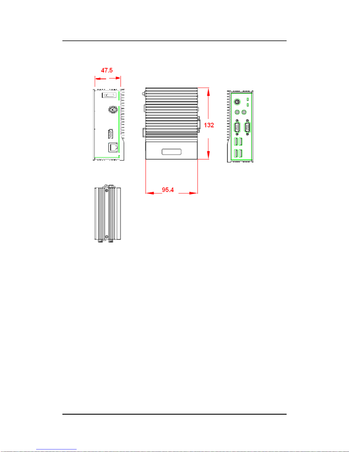
1.3 Dimensions
The following diagrams show you dimensions and outlines of the eBOX532-100-VGA-FL.
Page 14
eBOX532-100-FL Series User’s Manual
Introduction
6
eBOX532-100-PGA-FL.
Page 15
eBOX532-100-FL Series User’s Manual
Introduction
7
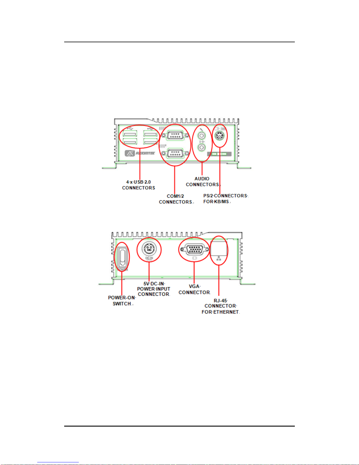
1.4 I/O Outlets
The following figures show you I/O outlets on front view of the eBOX532-100-VGA-FL &
eBOX532-100-PGA-FL
Front View
Rear View (eBOX532-100-VGA-FL)
Page 16
eBOX532-100-FL Series User’s Manual
Introduction
8
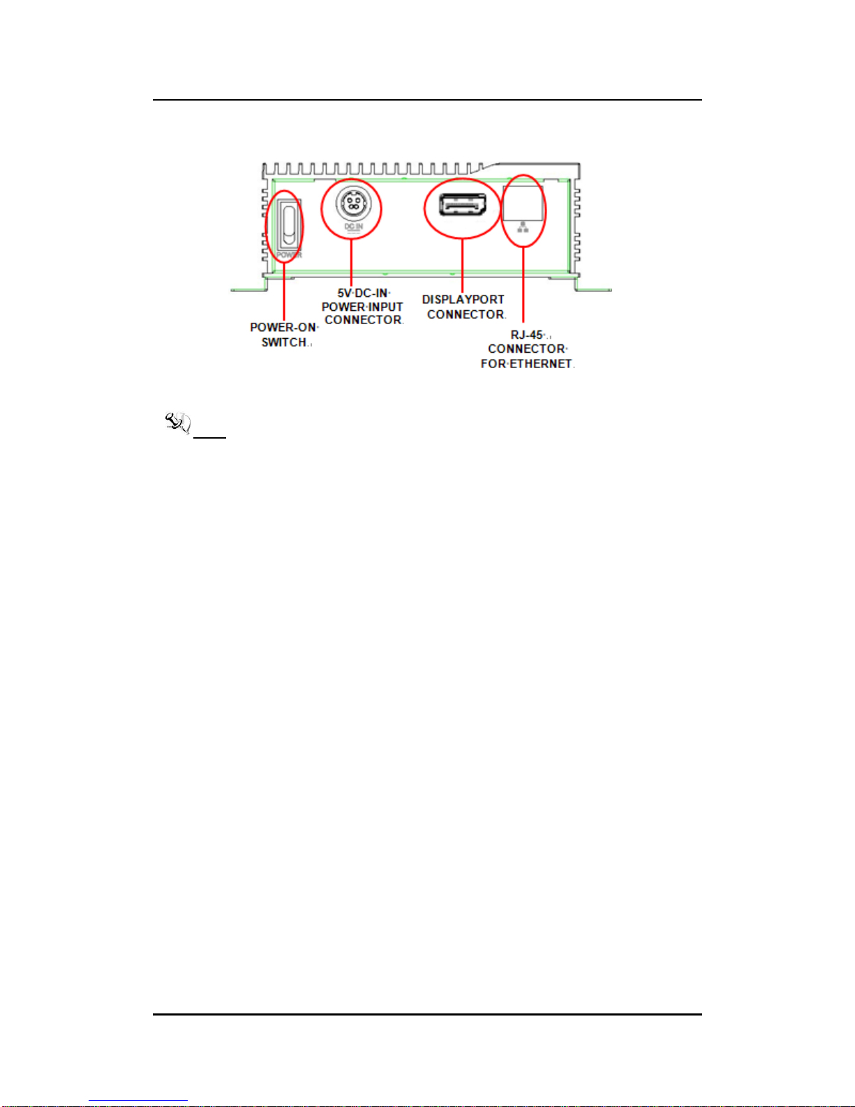
Rear View (eBOX532-100-PGA-FL)
NOTE P D (DisplayPort) Module
It is used for eBOX532-100-FL1.0G-PGA.
3 types of module are offered by option
- DisplayPort to HDMI Female Cable DP to HDMI
- DisplayPort to DVI Female Cable DP to DVI
- DisplayPort to VGA Female Cable DP to VGA
Page 17
eBOX532-100-FL Series User’s Manual
Introduction
9
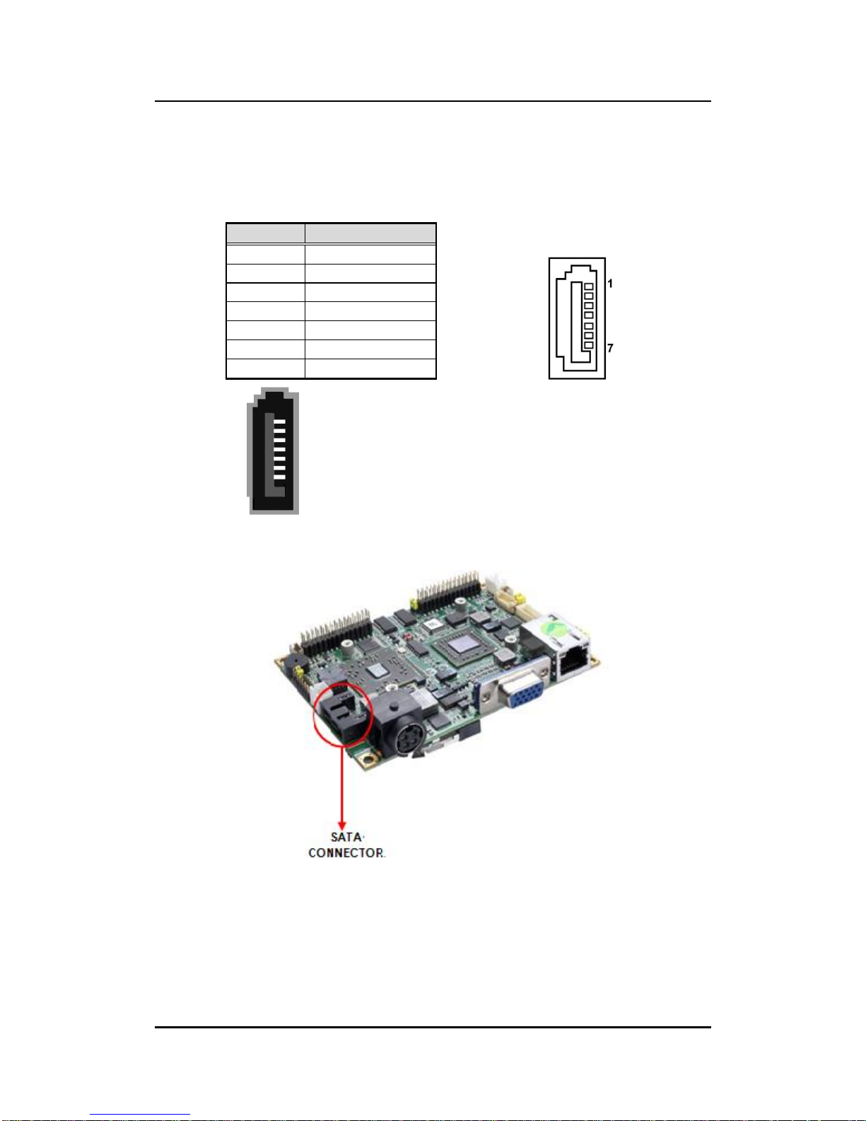
SATA Connector(SATA 1)
SATA connector is for high-speed SATA interface ports and each SATA
connector supports a single SATA device.
Plug one end of the SATA cable to the SATA connector, and the other end of
cable to the SATA hard drive.
Pin
Signal
1
GND
2
SATA_TX+
3
SATA_TX-
4
GND
5
SATA_RX-
6
SATA_RX+
7
GND
Page 18

eBOX532-100-FL Series User’s Manual
Introduction
10
1.5 Packing List
The package bundled with your eBOX532-100-FL should contain the following items:
eBOX532-100-FL System Unit x 1
eBOX532-100-FL Quick Manual x 1
Power Cord x 1
CD x 1 (For Driver and User’s Manual)
Wallmount Brackets
Keyboard/Mouse Y-cable
Screws
25W 5V AC/DC Power Adapter
HDD Mylar x1
(Figure – Power Adapter Pin Assignment)
If you can not find this package or any items are missing, please contact Axiomtek distributors
immediately.
NOTE P D (DisplayPort) Module
It is used for eBOX532-100-FL1.0G-PGA.
3 types of module are offered by option
- DisplayPort to HDMI Female Cable DP to HDMI
- DisplayPort to DVI Female Cable DP to DVI
- DisplayPort to VGA Female Cable DP to VGA
Page 19

eBOX532-100-FL Series User’s Manual
Hardware Installation
11
CHAPTER 2
HARDWARE INSTALLATION
The eBOX532-100-FL is convenient for your various hardware configurations, such as
Memory Module, HDD (Hard Disk Drive), and CompactFlashTM card. The chapter 2 will show
you how to install the hardware. It includes:
2.1 Installing the Memory Module
Step 1 Turn off the system, and unplug the AC/DC power cord.
Step 2 Turn the system upside down to locate screws at the bottom.
Step 3 Loosen these screws, and remove the back cover from the system.
Page 20

eBOX532-100-FL Series User’s Manual
Hardware Installation
12
Step 4 Locate the memory module as marked.
Step 5 Hold one side of the module, and insert the gold colored contact into the socket.
Push the module down.
Step 6 The memory module is locked by two latches on the sides.
Page 21

eBOX532-100-FL Series User’s Manual
Hardware Installation
13
NOTE hile uninstalling the Memory Module, you need to stretch these two latches aside,
and then take the module off the socket.
Step 7 Put the cover back to the system, and fasten screws tight close the chassis.
Page 22

eBOX532-100-FL Series User’s Manual
Hardware Installation
14
2.2 Installing the Hard Disk Drive
The eBOX532-100-FL offers a convenient drive bay module for users to install HDD. The
system offers users one 2.5” SATA-600 Hard Disk Drive for installation. Please follow the
steps:
Step 1 Turn off the system, and unplug the AC/DC power cord.
Step 2 Turn the system upside down to locate screws at the bottom.
Step 3 Loosen these screws, and remove the back cover from the system.
Page 23

eBOX532-100-FL Series User’s Manual
Hardware Installation
15
Step 4 HDD assembly parts include:
HDD Bracket x 1
2.5 inch HDD x 1
Screws x 4
HDD Mylar x1
Screw the 2.5 inch HDD, together with the HDD Mylar, to the HDD bracket.
Step 5 Fix the HDD bracket into the system, and plug the power cable in HDD.
Step 6 Put the cover back to the system, and fasten screws tight close the chassis.
Page 24

eBOX532-100-FL Series User’s Manual
Hardware Installation
16
2.3 Installing the CompactFlashTM Card
Step 1 Turn off the system, and unplug the AC/DC power cord.
Step 2 Turn the system upside down to locate screws at the bottom.
Step 3 Loosen these screws, and remove the back cover from the system.
Page 25

eBOX532-100-FL Series User’s Manual
Hardware Installation
17
Step 4 Locate the CompactFlashTM socket.
Step 5 Insert the CompactFlashTM card into the socket until it is firmly seated.
Page 26

eBOX532-100-FL Series User’s Manual
Hardware Installation
18
Step 6 Put the cover back to the system, and fasten screws tight close the chassis.
Page 27

eBOX532-100-FL Series User’s Manual
Hardware Installation
19
2.4 Installing DIN Mount (optional)
The eBOX532-100-FL provides DIN Mount that customers can install as below:
Step 1 Prepare DIN Mount assembling components (screws and bracket) ready.
MAXIMUM DEPTH OF THE HDD BRACKET: 2.5mm
DEPTH 2.5mm MAX.
Page 28

eBOX532-100-FL Series User’s Manual
Hardware Installation
20
Step 2 Assembly the bracket to the system, and fasten screws tight.
Page 29

eBOX532-100-FL Series User’s Manual
Hardware Installation
21
2.5 Installing Rail Mount
The eBOX532-100-FL provides Rail Mount that customers can install as below:
Step 1 Prepare Rail Mount assembling components (screws and bracket) ready.
Step 2 Assembly the bracket to the system, and fasten screws tight.
Page 30

eBOX532-100-FL Series User’s Manual
Hardware Installation
22
This page is intentionally left blank.
Page 31

eBOX532-100-FL Series User’s Manual
AMI BIOS Setup Utility 23
CHAPTER 3
AMI BIOS Setup Utility
The AMI UEFI BIOS provides users with a built-in setup program to modify basic system
configuration. All configured parameters are stored in a 16MB flash chip to save the setup
information whenever the power is turned off. This chapter provides users with detailed
description about how to set up basic system configuration through the AMI BIOS setup utility.
3.1 Starting
To enter the setup screens, follow the steps below:
1. Turn on the computer and press the <Del> key immediately.
2. After you press the <Del> key, the main BIOS setup menu displays. You can access the
other setup screens from the main BIOS setup menu, such as the Advanced and
Chipset menus.
NOTE If your computer can not boot after making and saving system changes
with Setup, you can restore BIOS optimal defaults by setting JP5 (see
section 2.4.3).
It is strongly recommended that you should avoid changing the chipset’s defaults. Both AMI
and your system manufacturer have carefully set up these defaults that provide the best
performance and reliability.
Page 32

eBOX532-100-FL Series User’s Manual
24 AMI BIOS Setup Utility
3.2 Navigation Keys
The BIOS setup/utility uses a key-based navigation system called hot keys. Most of the BIOS
setup utility hot keys can be used at any time during the setup navigation process. These
keys include <F1>, <F2>, <Enter>, <ESC>, <Arrow> keys, and so on.
NOTE Some of the navigation keys differ from one screen to another.
Hot Keys
Description
Left/Right
The Left and Right <Arrow> keys allow you to select a
setup screen.
Up/Down
The Up and Down <Arrow> keys allow you to select a
setup screen or sub-screen.
+ Plus/Minus
The Plus and Minus <Arrow> keys allow you to change
the field value of a particular setup item.
Tab
The <Tab> key allows you to select setup fields.
F1
The <F1> key allows you to display the General Help
screen.
F2
The <F2> key allows you to Load Previous Values.
F3
The <F3> key allows you to Load Optimized Defaults.
F4
The <F4> key allows you to save any changes you have
made and exit Setup. Press the <F4> key to save your
changes.
Esc
The <Esc> key allows you to discard any changes you
have made and exit the Setup. Press the <Esc> key to
exit the setup without saving your changes.
Enter
The <Enter> key allows you to display or change the
setup option listed for a particular setup item. The
<Enter> key can also allow you to display the setup
sub- screens.
Page 33

eBOX532-100-FL Series User’s Manual
AMI BIOS Setup Utility 25
3.3 Main Menu
When you first enter the setup utility, you will enter the Main setup screen. You can always
return to the Main setup screen by selecting the Main tab. System Time/Date can be set up
as described below. The Main BIOS setup screen is shown below.
System Language
Use this item to choose the system default language.
System Date/Time
Use this option to change the system time and date. Highlight System Time or System
Date using the <Arrow> keys. Enter new values through the keyboard. Press the <Tab>
key or the <Arrow> keys to move between fields. The date must be entered in
MM/DD/YY format. The time is entered in HH:MM:SS format.
Page 34

eBOX532-100-FL Series User’s Manual
26 AMI BIOS Setup Utility
3.4 Advanced Menu
Launch PXE OpROM
Use this item to enable or disable the boot ROM function of the onboard LAN chip
when the system boots up.
The Advanced menu also allows users to set configuration of the CPU and other system
devices. You can select any of the items in the left frame of the screen to go to the sub menus:
► ACPI Settings
► CPU Configuration
► IDE Configuration
► USB Configuration
► F81801 Super IO Configuration
► F81801 H/W Monitor
For items marked with “”, please press <Enter> for more options.
Page 35

eBOX532-100-FL Series User’s Manual
AMI BIOS Setup Utility 27
ACPI Settings
You can use this screen to select options for the ACPI configuration, and change
the value of the selected option. A description of the selected item appears on the
right side of the screen.
Enable ACPI Auto Configuration
Use this item to enable or disable BIOS ACPI auto configuration.
ACPI Sleep State
Default the Advanced Configuration and Power Interface (ACPI) state to be S3
(Suspend to RAM).
Page 36

eBOX532-100-FL Series User’s Manual
28 AMI BIOS Setup Utility
CPU Configuration
This screen shows the CPU Configuration, and you can change the value of the
selected option.
Node 0 Information
View memory information related to Node 0.
Page 37

eBOX532-100-FL Series User’s Manual
AMI BIOS Setup Utility 29
IDE Configuration
In the IDE Configuration menu, you can see the currently installed hardware in the SATA
ports. During system boot up, the BIOS automatically detects the presence of SATA devices.
Page 38

eBOX532-100-FL Series User’s Manual
30 AMI BIOS Setup Utility
USB Configuration
You can use this screen to select options for the USB Configuration, and change the value of
the selected option. A description of the selected item appears on the right side of the screen.
Legacy USB Support
Use this item to enable or disable support for USB device on legacy operating system.
The default setting is “Enabled”. Auto option disables legacy support if no USB devices
are connected. Disable option will keep USB devices available only for EFI applications.
USB transfer time-out
The time-out value for control, bulk and interrupt transfers.
Device reset time-out
USB mass storage device start unit command time-out.
Device power-up delay
Maximum time the device will take before it properly reports itself to the host controller.
“Auto” uses default value: for a root port it is 100ms, for a hub port the delay is taken
from hub descriptor.
Page 39

eBOX532-100-FL Series User’s Manual
AMI BIOS Setup Utility 31
F81801 Super IO Configuration
Serial Port Configuration
The configurations of serial port 0~1 are set “Enabled” as default.
Page 40

eBOX532-100-FL Series User’s Manual
32 AMI BIOS Setup Utility
F81801 H/W Monitor
This screen monitors hardware health.
This screen displays the CPU temperature, system temperature and system voltages (VIN0,
VIN1 and VBAT).
Page 41

eBOX532-100-FL Series User’s Manual
AMI BIOS Setup Utility 33
3.5 Chipset Menu
The Chipset menu allows users to change the advanced chipset settings. You can select any
of the items in the left frame of the screen to go to the sub menus:
► North Bridge
► North Bridge LVDS Config Select
► South Bridge
For items marked with “”, please press <Enter> for more options.
Page 42

eBOX532-100-FL Series User’s Manual
34 AMI BIOS Setup Utility
North Bridge Configuration
This screen allows users to configure parameters of North Bridge chipset.
Page 43

eBOX532-100-FL Series User’s Manual
AMI BIOS Setup Utility 35
Memory Configuration
Integrated Graphics
The Integrated Graphics controller configuration is set to “Auto”.
Node 0 Information
This item is to provide user with the information of current using DDR3 SDRAM.
Page 44

eBOX532-100-FL Series User’s Manual
36 AMI BIOS Setup Utility
North Bridge LVDS Config Select
DP0 Output Mode
Use this item to enable or disable LVDS.
LVDS Panel Config Select
Use this item to select configuration for LVDS panel if DP0 Output Mode is
enabled.
Page 45

eBOX532-100-FL Series User’s Manual
AMI BIOS Setup Utility 37
South Bridge
This screen allows users to configure South Bridge chipset. For items marked with
“ ”, please press <Enter> for more options.
► SB SATA Configuration
► SB USB Configuration
► SB HD Azalia Configuration
Page 46

eBOX532-100-FL Series User’s Manual
38 AMI BIOS Setup Utility
SB SATA Configuration
Use this item to select option for SATA configuration.
OnChip SATA Channel
Use this item to enable or disable SATA channel.
OnChip SATA Type
Here are the options: Native IDE and AHCI.
OnChip IDE mode
Here are the options: Legacy mode and Native mode.
Page 47

eBOX532-100-FL Series User’s Manual
AMI BIOS Setup Utility 39
SB USB Configuration
Use this item to enable or disable all USB devices.
SB HD Azalia Configuration
This item allows you to enable or disable HD audio Azalia device.
Page 48

eBOX532-100-FL Series User’s Manual
40 AMI BIOS Setup Utility
3.6 Boot Menu
The Boot menu allows users to change boot options of the system.
Setup Prompt Timeout
Number of seconds to wait for setup activation key. 65535(0xFFFF) means
indefinite waiting.
Bootup NumLock State
Use this item to select the power-on state for the NumLock.
Quiet Boot
Enable or disable Quiet Boot option.
Fast Boot
Use this item to enable or disable quick boot function. BIOS skips some certain
procedures to decrease time needed for booting up.
Page 49

eBOX532-100-FL Series User’s Manual
AMI BIOS Setup Utility 41
3.7 Security Menu
The Security menu allows users to change the security settings for the system.
Administrator Password
This item indicates whether an administrator password has been set (installed
or uninstalled).
User Password
This item indicates whether an user password has been set (installed or
uninstalled).
Page 50

eBOX532-100-FL Series User’s Manual
42 AMI BIOS Setup Utility
3.8 Save & Exit Menu
The Save & Exit menu allows users to load your system configuration with optimal or fail-safe
default values.
Save Changes and Exit
When you have completed the system configuration changes, select this option
to leave Setup and return to Main Menu. Select Save Changes and Exit from the
Save & Exit menu and press <Enter>. Select Yes to save changes and exit.
Discard Changes and Exit
Select this option to quit Setup without making any permanent changes to the
system configuration and return to Main Menu. Select Discard Changes and Exit
from the Save & Exit menu and press <Enter>. Select Yes to discard changes
and exit.
Save Changes and Reset
When you have completed the system configuration changes, select this option
to leave Setup and reboot the computer so the new system configuration
parameters can take effect. Select Save Changes and Reset from the Save &
Exit menu and press <Enter>. Select Yes to save changes and reset.
Page 51

eBOX532-100-FL Series User’s Manual
AMI BIOS Setup Utility 43
Discard Changes and Reset
Select this option to quit Setup without making any permanent changes to the
system configuration and reboot the computer. Select Discard Changes and
Reset from the Save & Exit menu and press <Enter>. Select Yes to discard
changes and reset.
Save Changes
When you have completed the system configuration changes, select this option
to save changes. Select Save Changes from the Save & Exit menu and press
<Enter>. Select Yes to save changes.
Discard Changes
Select this option to quit Setup without making any permanent changes to the
system configuration. Select Discard Changes from the Save & Exit menu and
press <Enter>. Select Yes to discard changes.
Restore Defaults
It automatically sets all Setup options to a complete set of default settings when
you select this option. Select Restore Defaults from the Save & Exit menu and
press <Enter>.
Save as User Defaults
Select this option to save system configuration changes done so far as User
Defaults. Select Save as User Defaults from the Save & Exit menu and press
<Enter>.
Restore User Defaults
It automatically sets all Setup options to a complete set of User Defaults when
you select this option. Select Restore User Defaults from the Save & Exit menu
and press <Enter>.
Launch EFI Shell from filesystem device
Attempt to launch EFI Shell application (Shellx64.efi) from one of the available
filesystem devices.
Page 52

eBOX532-100-FL Series User’s Manual
44 AMI BIOS Setup Utility
This page is intentionally left blank.
Page 53

eBOX532-100-FL Series User’s Manual
Warchdog Timer
45
APPENDIX A
Watchdog Timer
About Watchdog Timer
Software stability is major issue in most application. Some embedded systems are not
watched by human for 24 hours. It is usually too slow to wait for someone to reboot when
computer hangs. The systems need to be able to reset automatically when things go wrong.
The watchdog timer gives us solution.
The watchdog timer is a counter that triggers a system reset when it counts down to zero from
a preset value. The software starts counter with an initial value and must reset it periodically.
If the counter ever reaches zero which means the software has crashed, the system will
reboot.
How to Use Watchdog Timer
The I/O port base addresses of watchdog timer are 2E (hex) and 2F (hex). The 2E (hex) and
2F (hex) are address and data port respectively.
Assume that program A is put in a loop that must execute at least once every 10ms. Initialize
watchdog timer with a value bigger than 10ms. If the software has no problems; watchdog
timer will never expire because software will always restart the counter before it reaches zero.
Page 54

eBOX532-100-FL Series User’s Manual
Warchdog Timer
46
Begin
Enable and Initialize
Watchdog Timer
Program “A”
Disable Watchdog
Timer
Next
Next
Next
Next
Begin
Enable and Initialize
Watchdog Timer
Program “A”
Reset Watchdog
Timer
Next
Next
Next
Next
Page 55

eBOX532-100-FL Series User’s Manual
Warchdog Timer
47
Sample Program
Assembly sample code :
;Enable WDT:
mov dx,2Eh
mov al,87 ;Un-lock super I/O
out dx,al
out dx,al
;Select Logic device:
mov dx,2Eh
mov al,07h
out dx,al
mov dx,2Fh
mov al,07h
out dx,al
;WDT Device Enable:
mov dx,2Eh
mov al,30h
out dx,al
mov dx,2Fh
mov al,01h
out dx,al
;Activate WDT:
mov dx,2Eh
mov al,F0h
out dx,al
mov dx,2Fh
mov al,80h
out dx,al
;Set base timer :
mov dx,2Eh
mov al,0F6h
Page 56

eBOX532-100-FL Series User’s Manual
Warchdog Timer
48
out dx,al
mov dx,2Fh
mov al,Mh ;M=00h,01h,...FFh (hex),Value=0 to 255
out dx,al ;(see below
Note
)
;Set Second or Minute :
mov dx,2Eh
mov al,0F5h
out dx,al
mov dx,2Fh
mov al,Nh ;N=71h or 79h(see below
Note
)
out dx,al
Page 57

eBOX532-100-FL Series User’s Manual
Warchdog Timer
49
;Disable WDT:
mov dx,2Eh
mov al,30h
out dx,al
mov dx,2Fh
mov al,00h ;Can be disabled at any time
out dx,al
Note:
If N=71h, the time base is set to second.
M = time value
00: Time-out disable
01: Time-out occurs after 1 second
02: Time-out occurs after 2 seconds
03: Time-out occurs after 3 seconds
.FFh: Time-out occurs after 255 seconds
If N=79h, the time base is set to minute.
M = time value
00: Time-out disable
01: Time-out occurs after 1 minute
02: Time-out occurs after 2 minutes
03: Time-out occurs after 3 minutes
.
FFh: Time-out occurs after 255 minutes
Page 58

eBOX532-100-FL Series User’s Manual
Warchdog Timer
50
This page is intentionally left blank.
 Loading...