

Page 1

DSA-132 Series
31.5” Full HD Digital Signage with Intel
Core 2 Duo Processor
User’s Manual
Page 2

Disclaimers
This manual has been carefu l ly check ed and believed to contain
accurate information. AXIOMTEK Co., Ltd. assumes no responsibility
for an y infringements of patents or any third par ty’s rights, and any
liability arising from such use.
AXIOMTEK does not warrant or assume any leg al liability or
responsibility fo r the accuracy, completeness or usefulness of any
information in this document. AXIOMTEK does not make any
commitm ent to upd ate th e information in this manual.
AXIOMTEK reserves the rig ht to change or revise this d ocument
and /or product at any tim e with out notice.
No part of thi s document may be r eproduced , stored in a retr i eval
system, or transmitted, in any form or by any means, electronic,
mechanical, ph otocopying, recording, or otherwise, without the prior
written permissi on of AXIOMTEK Co., Ltd.
Copyright 2011 AXIOMTEK Co., Ltd.
All Rights Reserved
Apr 2011, Version A1
Printed in Taiwan
ii
Page 3

Safety Approvals
CE Marking
FCC Class A
FCC Complia nce
This equipment has been tes ted in compliance with the l imits for a
Class A digital device, pursuant to Part 15 of the FCC Ru l es. These
lim i ts are meant to provide reasonable protecti on against harmful
interferen ce in a residen tial install ation. If not installed and used i n
accordance with proper instructions, this equipment might generate or
radiate radio frequen cy energy and cause har mful in terference to
radio communications. However, there is no g uarantee that
interferen ce will not occ ur in a particular in stallation. If thi s equipment
does cause harmful interference to radio or television reception, whic h
can be det er mined by t urnin g the equipment off and on, the user is
encouraged to try to correct the i nterference by one or more of the
following methods:
1. Incr ease the separat i on between t he equipment and receiver.
2. C onnec t the eq uipm ent to an other outlet of a cir cuit that
doesn’t connect with the receiver.
3. C onsu lt the dealer or an experienced r adio/TV technician for
help.
Sh i elded in terface cables must be used in order to comp ly with the
emission limits.
iii
Page 4

Safety Precautions
Befor e gett i ng star ted, please read the following important safety
precautions.
1. The DSA-132 series does not come equipped with an
operat ing system. An operating system must be l oaded first
befor e installing any software into the computer.
2. Be sure to ground yourself t o prevent st atic charge wh en
ins talling the internal components. Use a grounding wrist
strap and place all electron i c components in any staticshi el ded devices. M ost electronic components are sensitive
to static electric al charge.
3. Disconnec t the p ower c or d from th e DSA-132 series before
any installation. Be sure both the sys tem and exter nal
devices are turned OFF. A sudden surge of power could ruin
sensitive components that the DSA-132 series mus t be
properly grounded.
4. Make sure it is the cor r ect voltage of the power source
befor e conn ectin g the equipment to the power outlet.
5. The bri ghtness of the flat p anel di splay wil l be gettin g weaker
as a result of fr equent usage. Howev er , th e operating period
varies depending on the appl ication environment.
6. The flat pan el display is not susc eptible to shock or vibr ation.
When assembling the DSA-132 series, make sure it is
securely install ed.
7. Do not leave this eq uipm ent in an uncontrol led environment
where the storage t emper ature is below 0℃ or above 40℃. It
may damage the equ ipment.
8. External equipment intended for conn ection to signal
input/out or oth er conn ectors s hall com ply with r el evan t
UL/IEC standard .
9. Do not open the back cover of the system. If opening the
cover for mainten ance is a m ust, only a trained technician is
allow ed to do so. In tegrated cir cuits on compu ter boards are
sensitive to static electricity. To a void damaging chip s from
electr ostatic dis charge, observe the following precaution s:
Befor e handling a board or i ntegrated circuit, touch an
unp ai nted portion of the s ys tem unit chassis for a few
seconds. This will help to discharge any static
electr i city on your b ody.
iv
Page 5

When handling boards and components, wear a wrist-
grounding strap, availab le from most electronic
component stores.
Trademarks Acknow ledgments
AXIOMTEK is a trademark of AXIOMTEK Co., Ltd.
IBM , PC/A T, PS/2, VGA are trademark s of Internat i onal
Business Machines Corporation.
®
and Atom™ are r egistered tr ademar ks of In tel Corporation.
Intel
MS-DOS, Mic r osoft C and Quick BASI C are trademarks of Microsoft
Corporation.
VIA i s a trad emark of VIA Technologies, Inc.
SST is a trademark of Silicon Stor age Technology, Inc.
UMC is a trademark of United M icroelectronics Corporation.
Other brand names and trademarks ar e the propert ies and registered
brands of t heir respecti ve owners.
v
Page 6

Table of Contents
Disclaimers ..................................................................... ii
Safety App rov als
Safety Precauti ons
CHAPTER 1 INTRODUCTION ......................................... 1
1.1 General Des cr ipti on .......................................... 1
Specifications ................................................... 2
1.2
1.2.1 Main CPU Board ....................................................... 2
I/O System ................................................................ 2
1.2.2
1.2.3
System Specification ................................................. 3
1.3 Dimensions ...................................................... 4
I/O Outlets ....................................................... 5
1.4
P ackage Lis t .................................................... 6
1.5
CHAPTER 2 HARDWARE INSTALLATION .................... 7
2.1 Slot in CPU B oard ............................................ 7
VESA Mounting Method ................................. 14
2.2
CHAPTER 3 PHOENIX-AWARD BIOS setup utility ...... 16
3.1 Starting .......................................................... 16
Nav igat ion Keys ............................................. 17
3.2
Mai n Menu ..................................................... 17
3.3
Standard CMOS setup Menu .......................... 18
3.4
A dvan ced BIOS Feat ures .............................. 22
3.5
Advanced Chipset Features ............................ 27
3.6
Integr ated Peripherals.................................... 28
3.7
3.8 Power Man agement S etu p ............................. 34
3.9 PnP/PCI Configuration Setup ......................... 34
PC H ealth Statu s ........................................... 38
3.10
3.11 Frequ enc y/Volt age C ont rol ............................. 38
3.12 Load Optimized Def aults ................................ 38
3.13 Set S uper vis or/ Us er Passwor d ....................... 38
3.14 Save & Exit Setup .......................................... 43
3.15 Exit Without Saving ....................................... 44
............................................................. iii
..........................................................iv
CHAPTER 4 DRIVERS INSTALLATION ....................... 46
4.1 System .......................................................... 46
vi
Page 7

CHAPTER 5 OSD Menu ................................................. 52
5.1 Hot ke y .......................................................... 52
vii
Page 8

MEMO
viii
Page 9

DSA-132 User’s Manual
CHAPTER 1
INTRODUCTION
This c hapt er contains general in formation and detai led specifications
of the DSA-132. Chapter 1 includes the following sections:
General Description
Specification
Dimensions
I/O Outlets
Pa ckag e List
1.1 General Description
The DSA-132 series is a Digital Signage computer which i s
equipped with 31.5-inch 450nits high brightness and Fu ll HD
(1920x1080p) TFT-LCD. The system supports superior Intel
Core 2 Duo processor. Power ed by Intel
logic ch ipset, this panel computer h as th e best pro ce s s or
performance. The DSA-132 can be deployed in a variety of
venues from shopping malls to corporate envi ronments, banks,
edu c at i on, hosp i t a l it y, res t aur ants and mor e. Th e r e i s a m odel
with touch s olution, DSA-132R is built in infrared touch sc reen.
DSA-132 has a high reliabi lity and easy maintain engine box, it is
more user-fri endly Di gital Signage com puter to ensure customer’s
project success and suited for digital signage applications.
®
945GC+ICH7 core
○R
Full HD TFT LCD
The DSA-132 is a full HD Digital Signage computer. The resolution is
1920x1080 which is ideal to displaying complex graphics and high
defin ition i mages, and it is suited by each kind of digital signage
application.
Introduction
1
Page 10

DSA-132 User’s Manual
NOTE Due to protecting LCD, we suggest to use DSA-132 in
the upr ight positi on .
Spill and dust resistant
The DSA-132 has designed front bezel by IP65 water-proof,also
the entir e system is protected. Therefore the system is
protected from water drip dam ages.
Easy maintenance
The DSA-132 series has pluggable engine box design; you can
change HDD, DRAM and CP U configurations more easily.
1.2 Specifications
1.2.1 Main CPU Board
CPU
LGA775 sock et for Intel
Celeron Pr ocess or with FSB 533/800MHz
System Chipse t
Intel
BIOS
Phoenix-Award
System Memory
Two 240-pin DDR2 SO-DIMM socket
Maximum memory up to 2GB
®
945GC + ICH7
1.2.2 I/O System
Standard I/O
One VGA
One DVI-D
Four USB ports 2.0 comp l iant
Two RS-232 port
2
®
CoreTM 2 Duo / Pentium /
Introduction
Page 11

Ethernet
Two Gigabit Ethernet
Audio
Realtek High Definit ion c odec audio
1.2.3 System Specification
31.5” TFT LCD
Brightness - 450 cd/m2
Resolution - 1920 x 1080
Disk drive housing:
One 2.5” SATA drive
Net Weight
25.5 Kg
Dimension (Main Body Size)
781x 471 x 134mm ( DS A-132G )
781x 471 x 1 34mm ( DSA-132R )
DSA-132 User’s Manual
O peration Temperature
0℃ to 40℃
NOTE
All specifications and images are subject to change
witho ut no ti ce.
Introduction
3
Page 12

DSA-132 User’s Manual
1.3 Dimensions
This diag r am shows you dimensions and outlines of the DSA-132.
4
Introduction
Page 13

DSA-132 User’s Manual
2
1
2 3 4 5 6
1.4 I/O Outlets
The following figures show you the locations of the DSA-132 Series
I/O outlets.
No. Connector No. Connector
1
3
5
7
Introduction
Power connector
K/B+M/S
VGA/DVI
Audio
2 Slot in holder
4
COM
6
2 x LAN / 4 x USB
5
Page 14

DSA-132 User’s Manual
1.5 Package List
When you receive the DSA-132, the bundled p ackage s hould contai n
the following items:
DSA-132 device x 1
Power cord x 1
CD x 1 (For Drivers)
If you can not find the package or any items are missing , please
contact AXIOMTEK distributors immediately.
6
Introduction
Page 15

DSA-132 User’s Man ual
7
CHAPTER 2
HARDWARE INSTALLATION
The DSA-132 Series are con venient for your various hardware
configurations, such as HDD (Hard Disk Drive), Memory Module. The
chapter 2 will show you how to install the har dware. It inc l udes:
CPU, Har d disk Drive and DRAM Installation
Mounting Method
2.1 Slot in engine box
The DSA-132 Series offers a convenient drive bay module for users
to install DRAM, CPU and HDD. Pleas e follow t he steps:
Step 1 Turn off the system, and unplug the power cord.
Hardware Installation
Page 16

DSA-132 User’s Manual
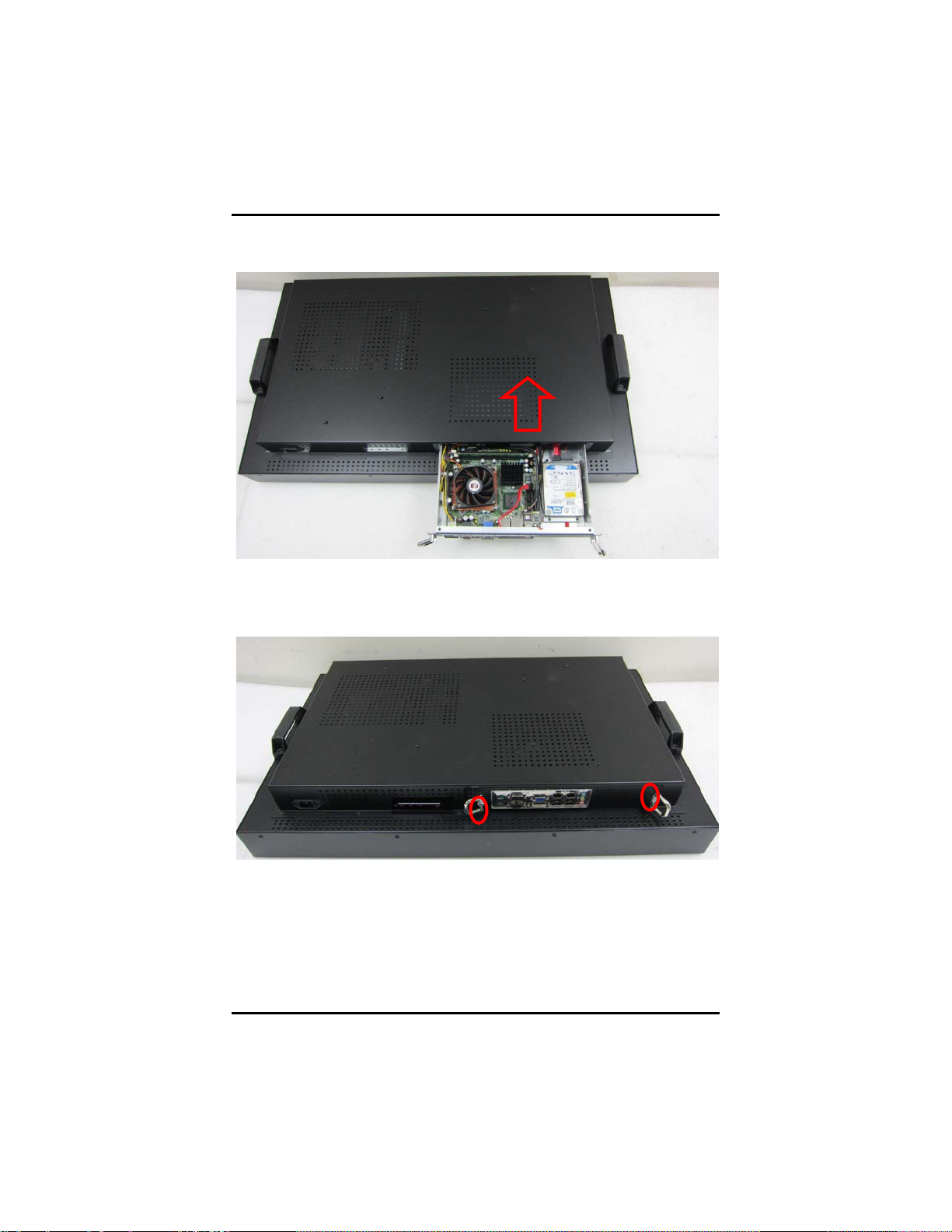
Step 2 Loosen the screws as illu strated.
Step 3 Pull out the engine box via the rings as marked.
8
Hardware Installation
Page 17

DSA-132 User’s Man ual
9
Step 4 Loosen the screws as illus tration and then pull out fan
connector.
Hardware Installation
Page 18

DSA-132 User’s Manual
Step 5 Remove the fan.
Step 6 Install CP U and fan. Put CPU and turn on the latch as mark.
Then put the fan above t he CPU , locate and fasten sc r ews as
mark.
10
Hardware Installation
Page 19

DSA-132 User’s Man ual
11
Step 7 Install the Hard Drive. L ocate and fasten screws as m ar k and
plug in power cable.
Hardware Installation
Page 20

DSA-132 User’s Manual
Second
Step 8 Plug in SAT A cable.
Step 9 P l ace the memory m odule i nto th e socket and pres s it firmly
down u ntil it is fully located. The socket latches are levered
upwards and clipped on to the edges of the DI M M . If you
would only u se one p i ece DRAM, please install first s lot.
12
First
Hardware Installation
Page 21
13
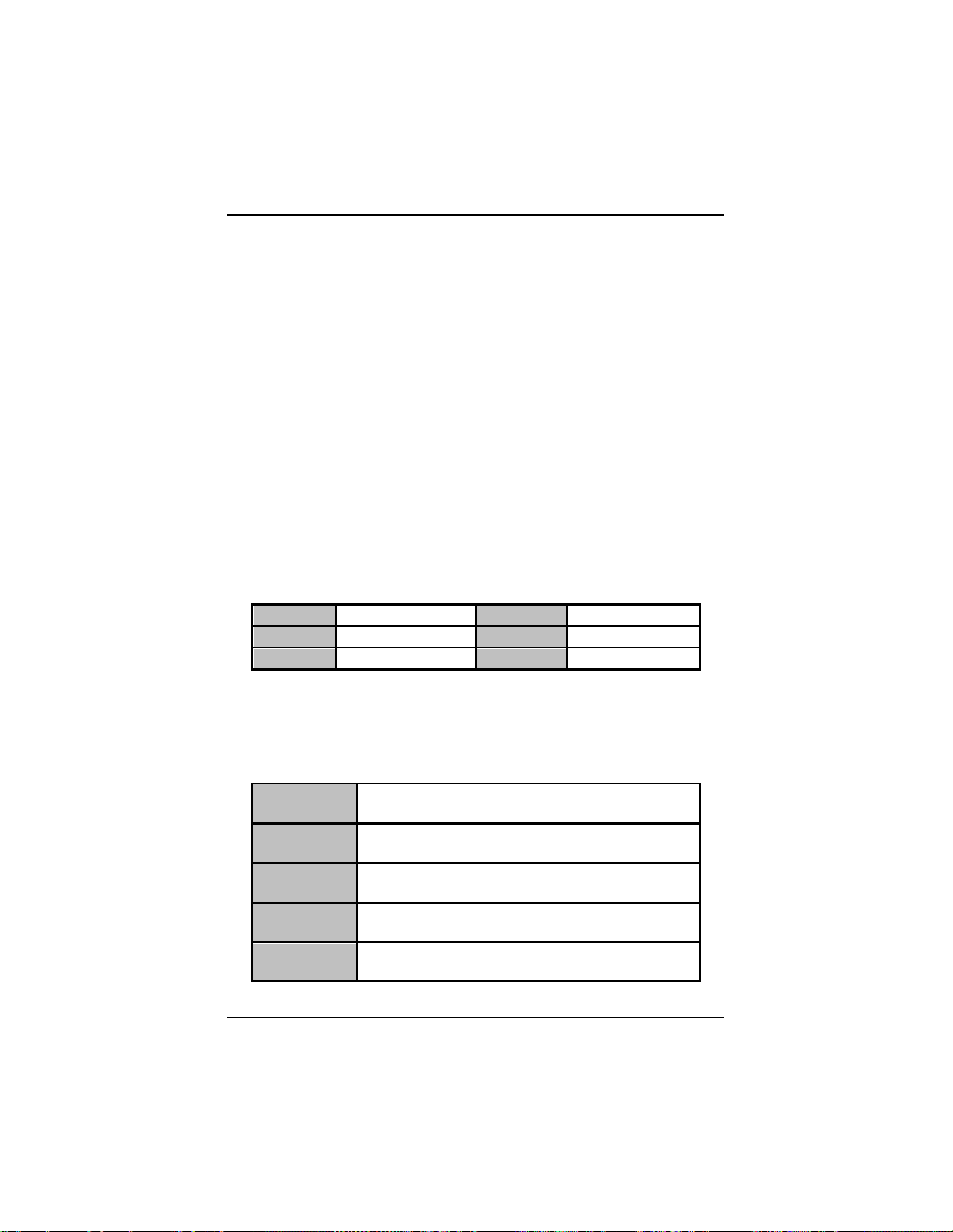
Step 10 Slot engine box into the sock et.
DSA-132 User’s Man ual
Step 11 Fasten the screws as illustrated
Hardware Installation
Page 22

DSA-132 User’s Manual
2.2 VESA Mounting Method
DSA-132 supports the standard 200 and 400 VESA mount. The phot o
is as below.
14
Hardware Installation
Page 23

15
MEMO
DSA-132 User’s Man ual
Hardware Installation
Page 24

DSA-132 User’s Manual
CHAPTER 3
PHOENIX-AWARD BIOS SETUP UTILITY
This chapter provides users with detailed description how to set up
basic system configuration through the Phoenix-Award BIOS setup
utility.
3.1 Starting
There ar e two ways to ent er the S etup program. You m ay either turn
ON t he computer and press < D el> immediatel y, or press the <Del>
and /or <Ctr l > , <Alt>, and <Esc> keys simultaneousl y when th e
fol lowing message appear s at the bottom of the sc r een duri ng POS T
(Power on Self Test).
TO ENTER SETUP PRESS DEL KEY
If the message dis appears before you r espon d and you st i ll want to
enter Setup, please restart the system to try it again. Turning the
system power OFF and ON, pr essing the “RESET” button on t he
system case or simultaneously pressing <Ctrl>, <Alt>, and <Del> keys
can restart the sys tem. If you do not pres s keys at the right time and
the system doesn’t boot, an er r or message will pop out to prom pt you
the following inform ation:
PRES S <F1> TO CO NT INUE, <CTRL-ALT-ESC> OR <DEL> TO ENTER SETUP
To enter the setup screens, follow the steps bel ow:
1. Turn on th e comput er and press the <D el> key immediately.
2. After you p r ess the <Delete> key, th e main BIOS setup menu
displays. You can access the other setup screens from the main
BIOS setup menu, such as the Chipset and P ower menus.
16
PHOENIX-AWARD BIOS Setup Utilit y
Page 25

DSA-132 User’s Man ual
3.2 Navigation Keys
The BIOS s etup/utility uses a key-based navigation system cal led hot
keys. Most of the BIOS setup utili ty hot keys can be used at any tim e
du r i ng the setup navigation process.
These keys incl ude <F1>, <F10>, <Enter>, <E SC>, <Arrow> keys, and
so on.
Note
Some of navi g ation keys dif f er from one scree n to an other.
3.3 Main Menu
Once you enter th e Award BIOS CMOS Setup Utility, the Main M enu
appears on the screen. In the Main Menu, ther e ar e several Setup
function s and a couple of Exit options for your selection. Us e ar r ow
keys to s elect the Setup Page you i ntend to configure t hen press
<En ter> to ac cept or enter its sub-menu.
NOTE
It i s strongly recom mended that you should avoid c hanging the
chipset’s defaults. Both Award and your system manufacturer have
PHOENIX-AWARD BIOS Setup Utilit y
If y our computer can not boot after making and saving
system changes wit h S etu p, th e Aw ar d BI OS will reset
your system to the CMOS default settings via its built-in
override feature.
17
Page 26

DSA-132 User’s Manual
to Saturday.
month
It is from January to December.
year
It shows the current year of BIOS.
carefully set up these default s that provide t he bes t performance and
reliability.
3.4 Standard CMOS Setup Menu
The Standar d CMOS Setup Menu disp l ays basic inform ation about
you r s ystem. Use arrow keys to highlight each item, and use <PgUp>
or <PgDn> k ey to select the value you want in each i tem.
Date
The date format is <d ay>, <d ate> <month> <year>. Press <F3> t o
show the calendar.
day
date
Time
18
It is determined by the BIOS and read only, from Sunday
It can be keyed with the numerical/ function key, from 1
to 31.
PHOENIX-AWARD BIOS Setup Utilit y
Page 27

DSA-132 User’s Man ual
This item s hows cur r ent t ime of your system with the format
<hour> <minute> <second>. The time is cal culat ed based on the
24-hour military-time clock. For example, 1 p.m. i s 13:00:00.
PHOENIX-AWARD BIOS Setup Utilit y
19
Page 28
DSA-132 User’s Manual
CYLS.
number of cylinders
LANDZONE
landing zone
HEADS
number of heads
SECTORS
number of sectors
PRECOMP
write precom
MODE
HDD acce ss mo de
(default)
system will stop and you will be prompted.
Keyboard
error; it will stop for other errors.
Diskette
will stop for other errors.
Disk/Key
disk error; it will stop for other errors.
IDE Channel 0/1/2/3 Master/Slave
These items identify the types of each IDE channel installed in the
computer. There are 45 predefined types (Type 1 to Type 45) and
2 user’s definable types ( Type User) for Enhance d ID E BIO S.
Press <PgUp>/<+> or <PgDn>/<−> to s elect a numbered hard
disk type, or directly type the number and press <Enter>. Please
be n oted your drive’s specificat ions must match the drive tab le.
The hard disk will not work properly if you enter improper
information. If you r hard disk drive type does n ot match or is not
listed, you c an us e Type U ser to manually define your own drive
type.
If selec ting Type Use r , you will be ask ed to enter related
information in t he following items. Directly key in the in formation
and press <Enter>. This information should be provided in the
documentation from your hard disk vend or or the system
manufacturer.
If the HDD interface c ontroller supp or ts ESD I, select “Type 1”.
If the HDD interface c ontroller supp or ts SCS I, select “None”.
If the HDD interface c ontroller supp or ts CD-ROM, select “None”.
If there is no hard di sk drive in stalled, select NO N E and press
<Enter>.
Halt On
This item determines whether the syst em will h al t or not, if an er r or
is d etected while powering up.
No errors
All errors
All, But
All, But
All, But
The system booting will halt on any errors detected.
Whenever BIOS detects a non-fatal error, the
The system booting will not stop for a keyboard
The system booting will not stop for a disk error; i t
The system booting will not stop for a keyboard or
20
PHOENIX-AWARD BIOS Setup Utilit y
Page 29

Press <Esc> to return to the Main Menu page.
DSA-132 User’s Man ual
PHOENIX-AWARD BIOS Setup Utilit y
21
Page 30

DSA-132 User’s Manual
3.5 Advance d BIOS Features
This section allows you to config ure and impr ove y our syst em, to set
up some system features accor ding to your preference.
22
PHOENIX-AWARD BIOS Setup Utilit y
Page 31

DSA-132 User’s Man ual
CPU Fea tur e
Scrol l to this it em and press <Enter> to vie w t he CPU Feature sub
menu.
Delay prior to Thermal
This filed is used to select the time that would force the CPU
to a 50% duty c ycle when it exceeds its maximum operating
tem perature therefore p r otecti ng th e CPU and the system
board from overheating to ensure a safe compu ting
environment.
Ther m al Ma nagement
Therm al M onitor 1 On-die throttling
Therm al M onitor 2 Rati o and VI D trans it i on
Limit CPUID MaxVal
The CPUID instruction if som e n ewer CPUs will return a
value greater than 3. The default is “Disabled“, bec ause this
problem does not exist in the Windows series operating
systems. If you are using an operating system other than
Windows, this problem may occur. To avoid this problem,
you can enabl e this field t o limit the ret urn value to 3 or
lesser than 3.
Press <Esc> to return to the Advanced BIOS Features page.
PHOENIX-AWARD BIOS Setup Utilit y
23
Page 32

DSA-132 User’s Manual
Enabled
Enable cache
Disabled
Disable cache
Enabled
Enable Quick POST
Disabled
Normal POST
Hard Disk Boot Priority
Scroll to this item and press <Enter> to view the sub menu to
decide the disk boot priority.
Press <Esc> to return to the Advanced BIOS Features page.
CPU L1 & L2 Cache
These two options speed up memory access. However , it depends
on the CPU/chipset design. The default setting is “Enabled”. CPUs
without built-in intern al cache will not provide the “CPU Int er nal
Cach e” i tem on the menu.
Quick Power On Self Test
This option speed s up Power on Self Test ( POS T) after you tur n on
the system power. I f s et as Enabled, BIOS will short en or ski p some
check items during POST. The default setting is “Enabled”.
First/Second/Third Boot Device
24
PHOENIX-AWARD BIOS Setup Utilit y
Page 33

DSA-132 User’s Man ual
will not boot, the access to Setup will be denied, either.
will boot, but the access to Setup will be denied.
These items l et you select the 1st, 2nd, and 3rd devices that th e
system will search for during its boot-u p sequence. There is a wide
range of options for your selection.
Boot Other Device
This item all ows the user to enab l e/disable th e boot device not
list ed on the First/Second/Th i r d boot devices op tion above. The
default setting is “Enabled”.
Boot Up NumLock Status
Set the the Num Lock statu s when th e system is powered on.
The default value is “On”.
Securi ty Option
This item all ows you to lim it access to th e system and Setup, or
jus t to Setup. The default value is “Setup”.
System
Setup
NOTE
If a wrong password is entered at the prompt, the system
If a wrong password is entered at the prompt, the system
To disable the security, select PASSWORD
SETTING at Main Menu and then you will be
asked t o en ter a password. Do not ty p e anything,
just press <Ente r> and it will disab le the security.
Once the security is disabled, the system will boot
and you can enter Setup freely.
APIC Mode
Use this item to enable or disable APIC (Advanced Programmable
Interrupt Controller) mode that provides symmetric multiprocessing (SMP) for systems.
MPS Version Control For OS
This item specifies the version of the Multiprocessor Sp ecification
(MPS). Ver sion 1.4 has extended configuration tab l es to improve
support for multiple PCI bus configurations and provide future
expandability.
PHOENIX-AWARD BIOS Setup Utilit y
25
Page 34

DSA-132 User’s Manual
OS Selec t f or DRAM > 64MB
This item all ows you to access the m emory over 64MB in OS/2.
Report No FDD For WIN 95
Select Yes to release an IRQ when th e system doesn’t have any
flopp y drive, for compati bility with W i ndows 95 logo c er tificat i on. I n
the Integ r ated P er ipherals screen, select Disabled fo r the O nboard
FDC Controller field.
Pre ss < Es c > to ret u rn to the Main Menu page.
26
PHOENIX-AWARD BIOS Setup Utilit y
Page 35

DSA-132 User’s Man ual
3.6 Advanced Chipset Features
This s ection allows you to configu r e and im prove your system, to set up
some system features according to your preference.
PHOENIX-AWARD BIOS Setup Utilit y
27
Page 36

DSA-132 User’s Manual
PCI-E Compliancy Mode
This item allows users to set the version of the P CI Express based
on the specification by which the motherboard h as to comply.
*** VGA S etting ***
PEG/Onchip VGA Control
Use this item to choose the prim ar y display card.
On-Chip Frame Buffer Size
Use this item to s et the VGA frame buffer size.
DVMT Mode
DVMT (D ynamic Video M emory Technology) helps you selec t the
video mode.
DVMT/Fixed Memory Size
DVMT (D ynamic Video M emory Technology) allows you t o select
a maximum s ize of dynamic amount usage of the video memor y.
The system would configure the video memory depen dent on your
application.
Boot Display
This item is to select Display Device that the screen will be shown.
Panel Scaling
This item s hows th e setti ng of pan el scaling and operates the
scaling function that the pan el output can fit the sc r een resolution
connected to the output port.
Panel Number
This item is to select panel resolution that you want.
Press <Esc> to return to the Main Menu page.
28
PHOENIX-AWARD BIOS Setup Utilit y
Page 37

DSA-132 User’s Man ual
3.7 Integrated Peripherals
This section allows you to config ure your OnChip IDE Device,
Onboar d Device and SuperIO Device.
PHOENIX-AWARD BIOS Setup Utilit y
29
Page 38

DSA-132 User’s Manual
OnChip IDE Device
Scrol l to this it em and pr ess <Enter> to vi ew the sub menu OnC hi p
IDE Device.
IDE HDD Block Mode
Block m od e is also c alled b loc k t ran sfer, m ult ip le com m ands ,
or multipl e sector read/write. I f your IDE hard drive suppor ts
bloc k mode (most new d r i ves do), select En abled for
automatic detection of the optimal num ber of block
read/ writes per sec tor the drive can support.
IDE DMA transfer access
Au tomatic data t r ansfer b etween syst em memory and IDE
device with min imum CPU intervention. This improves data
thr oughput and frees CPU to perform oth er tasks.
On-Chip Primary/Secondary PCI IDE
The integrated per ipher al controller contains an IDE
interface with support for two IDE channels. Select Enabled
to activate each chann el separately. The default value is
“Enabled”.
Choosing Disabled for these options will
NOTE
automatically remove the IDE Primary Master/
Slave PIO and/or IDE Secondary Master/Slave
PIO items on the menu.
30
PHOENIX-AWARD BIOS Setup Utilit y
Page 39

DSA-132 User’s Man ual
IDE Primary/Secondary Master/Sla ve PIO
The four IDE PIO (Programmed Input/Out put) fiel ds let you
set a PIO mode (0-4) fo r each of the four IDE devices that
the onboard IDE interface suppor ts. M odes 0 to 4 provide
successively increased performance. In Auto mode, the
system automatically determi nes the best m ode for each
device.
IDE Primary/Secondary Master/Slave UDM A
Select th e m ode of operation for the IDE drive. Ultra DMA33 /66/10 0/133 implem entation is possible only if your IDE
hard drive supports it and the op er ating environmen t
includes a DMA driver. If your hard drive and system
software bot h support U ltra DMA-33/66/100/133, sel ect Auto
to enable UDMA mode by BIOS .
SATA Mode
There ar e these options for you to set up SATA mode: IDE
or RAID.
SATA PORT Speed Settings
Use this item to sel ect SATA I or SATA II device support
forcedly.
Press <Esc> to return to the Integrated Perip herals page.
PHOENIX-AWARD BIOS Setup Utilit y
31
Page 40

DSA-132 User’s Manual
Onboard Device
Scroll to this item and press <Enter> to view the sub menu
Onboard Device.
USB Controller
Enable th is item if you ar e using the US B in the s ystem. You
should disable this item if a higher-level controller is added.
USB 2.0 Controller
Enable th is item if you are using the EHCI (USB2.0)
controller in the system .
USB Keyboard Support
En able this item if the system has a Univers al Serial Bus
(USB) controller, and you have a USB keyboard.
AC97 Audio Select
Use this item to en able or d isable the onb oar d AC97 A udi o
function.
Press <Esc> to return to the Integrated Perip herals page.
32
PHOENIX-AWARD BIOS Setup Utilit y
Page 41

DSA-132 User’s Man ual
Super IO D evice
Scroll to this item and press < Enter> to view th e sub menu Super
IO D evice.
Onboard Serial Port 1/2
Select an address and corr esponding interru pt for th e serial
port.
PWRON After PWR-Fail
This item enables your com puter t o automatic al ly restart or
retu r n to its operating s tatus.
Press <Esc> to return to the Integrated Perip herals page.
Onboard Serial Port 3/4/5/6
Select an address and corr esponding interru pt for th e serial por t.
Onboard Lan Boot ROM
Use this item to enable or disab l e the Boot ROM fu nction of the
onboard LAN chip when the system boot s up.
Press <Esc> to retu r n to the Main Menu page.
PHOENIX-AWARD BIOS Setup Utilit y
33
Page 42

DSA-132 User’s Manual
3.8 Power Management Setup
The Power Management Setup allows you to save energy of your
system effectivel y. It will shut d own the hard disk and turn OFF video
display after a period of inactivity.
ACPI Function
This item all ows you to enable/disable the Ad vanced C onfiguration
and Power Manag ement (ACPI). The function is always “Enabled”.
ACPI Suspend Type
This it em specifies the power saving mod es for ACPI function. If
your operating system supports ACPI, such as Windows 98SE,
Windows ME and Windows 2000, you can choose to enter the
Standby mode in S1 (POS) or S3 (STR) fashion through the
setting of this field. O ptions ar e:
[S1(POS)] The S 1 sl eep mod e is a lo w power s tat e. I n th is st ate,
no system c ontext is lost ( C PU or chips et) and hardware maintains
all system context.
[S3(STR)] The S3 sleep m ode is a lower power state where
the information of s ys tem c onfiguration and open
34
PHOENIX-AWARD BIOS Setup Utilit y
Page 43

DSA-132 User’s Man ual
CPUs. The inactivity period is 1 minute in each mode.
Timers section.
It is minimum power savings. The inactivity period is 1
hour in each mode (except the hard drive).
Disabled
Default value
video buffer
management values.
Blank Screen
applicati ons/fi l es is sav ed to main memory that rem ains
powered while most oth er hardware component s turn off to s ave
energy. The in formation s tored in memor y w ill be used to restore
the system when a “wake up” event occurs.
Power Man agement
This option allows you to s el ect the type (or degree) of power
saving for Doz e, St andby, and Suspend modes. Th e table below
describes each power management mode:
Max Saving
It is maximum power savings, only available for SL
User Define
Min Saving
Video Off Method
It sets each mode. Select time-out periods in the PM
Thi s se tti ng determines the manner in which the monitor is blanked.
V/H
SYNC+Blank
DPMS
Video Off I n Suspend
Turns OFF vertical and horizontal
synchronization ports and writes blanks to the
Select this option if your monitor supports the
Display Power Management Signaling (DPMS)
standard of the Video Electronics Standards
Association (VESA). Use the software supplied
for your video subsystem to select video power
System only writes blanks to the video buffer.
This item defines i f the video is pow ered down when the system i s
put into suspend mode.
Suspend Type
If this it em is set to the defaul t St op Grant, the CPU will go into Idle
Mode during power saving mode.
Suspend Mode
After the sel ected period of system i nactivity (1 minute to 1 hour ) ,
all devices except the CPU shut off. The default value is
“Disabled”.
PHOENIX-AWARD BIOS Setup Utilit y
35
Page 44
DSA-132 User’s Manual
Disabled
System will never enter SUSPEND mode
Min/1 Hr
power OFF sequence requiring only the switching of the
power supply button to OFF
delay period, system will temporarily enter into Suspend
Defines the continuous idle time before the s ystem
1/2/4/6/8/10/2
0/30/40
HDD Power Down
entering SUSPEND mode.
If any item defined in (J) is enabled & active,
SUSPEND timer will be reloaded
If HDD activit y is not detected for the length of time specified in
this field, t he hard disk drive will be powered down while all other
devices rem ai n active.
Soft-Off by PWR-BTTN
This option only works with systems using an ATX power supp l y. It
also allows t he us er to define which type of soft power OFF
sequence the system will fol low. The default value is “I nstant-Off”.
This option follows the conventional manner systems
Instant-Off
Delay 4 Sec.
Power On by Ring
perform when power is turned OFF. Instant-Off is a soft
Upon turning OFF system from the power switch, this
option will delay the complete system power OFF
sequence by approximately 4 seconds. Within this
Mode enabling you to restart the system at once.
This option allows t he system to resume or wake up upon detecting
any ring signals coming from an installed modem . Th e default value
is “Enabled”.
Resume by Alarm
If enable this it em , the system c an automatically resume after a
fixed time i n accordanc e with the system’s RTC (realtim e clock).
Primar y/Secondary ID E 0/1
Use this item to con fi gure the IDE d evices monitored by the
system.
FDD, COM, LPT Port
Use this item t o config ure the FDD, COM and LPT p or ts m onitored
by the sys tem.
Press <Esc> to return to the Main Menu page.
36
PHOENIX-AWARD BIOS Setup Utilit y
Page 45

DSA-132 User’s Man ual
PHOENIX-AWARD BIOS Setup Utilit y
37
Page 46

DSA-132 User’s Manual
3.9 PnP/PCI Configuration Setup
This section describes the con fi guration of PCI (Personal Computer
Interconnect) bus system, which allows I/ O devices to operate at
speeds cl ose to the CPU speed while communicat i ng with other
important components. This section covers ver y technical items that
only experienced user s could change default set tings .
Reset Configuration Data
Normally, you leave this item Disabled. Select Enabled to reset
Extended System C onfiguration Data (ESCD) wh en you exit Setu p
or if installing a new add-on cause the system reconfigu r ation a
serious con flict t hat t he operating sys tem c an not boot . Options:
Enabled, Disabled.
Resources Controlled By
The Awar d Plug and P lay BIOS can automatically confi gure all
boot and Plug and Play-compatib l e devices. If you select Aut o, all
interrupt request (I R Q), DMA assignm ent, and Used DMA fi el ds
dis appear, as the BIOS automatically assi gns them. The defau lt
value is “Manual”.
IRQ Resources
When resources are controlled manuall y, assig n each system
38
PHOENIX-AWARD BIOS Setup Utilit y
Page 47

DSA-132 User’s Man ual
interrupt to one of the following types in accordance with the type
of devices using the interrupt:
1. Legacy ISA Devices compliant with the original PC AT bus
specification, requiring a specific interrupt (such as IRQ4 for serial port
1).
2. PCI/ISA PnP Devices compliant with the Plug and Play standard,
whether designed for PCI or ISA bus architecture.
The default value is “PCI/ISA PnP”.
PCI/VGA Palett e Sno op
Some non-standard VGA display card s may not show col or s
properly. This item allows you to set whether MPEG ISA/VESA
VGA C ar ds can work with PCI/VGA or not. Wh en enabled, a
PCI/VGA can work with a MPEG ISA/VESA VGA card; when
disabled, a PCI/VGA cannot work with a MPEG ISA/VESA Card.
** PCI Express relative items **
Maximum Payload Size
When using D DR SDRAM and Buffer si ze sel ection , another
consideration in desi gning a payload memory is the si ze of the
bu ffer for dat a storag e. Maximum Payload Size defines the
maximum TLP (Transaction Layer Packet) d ata payl oad size for
the device.
Press <Esc> to return to the Main Menu page.
PHOENIX-AWARD BIOS Setup Utilit y
39
Page 48

DSA-132 User’s Manual
3.10 PC Health Status
This s ection supp or ts har dware monitering th at lets you monitor th ose
parameters for critical voltages , temperat ures an d fan speed of the
board.
Current S YSTEM Temperature
Sh ow you th e current system temperature.
Current CPU Temperature
These r ead -onl y fi eld s show t h e fun ct ion s of th e hard ware t h erm al
sensor by CPU thermal diode that monitors the chip blocks to
ensure a st able system.
Vcore/1.8V/3.3V/12V/VCC
Sh ow you th e voltage of Vcore/1.8V/3.3V/12V/VCC.
Press <Esc> to return to the Main Menu page.
40
PHOENIX-AWARD BIOS Setup Utilit y
Page 49

DSA-132 User’s Man ual
3.11 Frequency/Voltage Control
This s ection is to control the CPU frequency and Supply V oltage, DIMM
OverVoltage and AGP voltage.
Auto Detec t PCI C lk
The enabled item can autom atically disab l e the clock source for a
PCI slot without a module, to reduce EMI (Electr oM agnetic
Interference).
Spread Spectrum
If spread spectrum is enabled, EMI (Electr oM agnetic Interference)
gen er ated by the system c an be significantly reduced.
Press <Esc> to return to the Main Menu page.
PHOENIX-AWARD BIOS Setup Utilit y
41
Page 50
DSA-132 User’s Manual
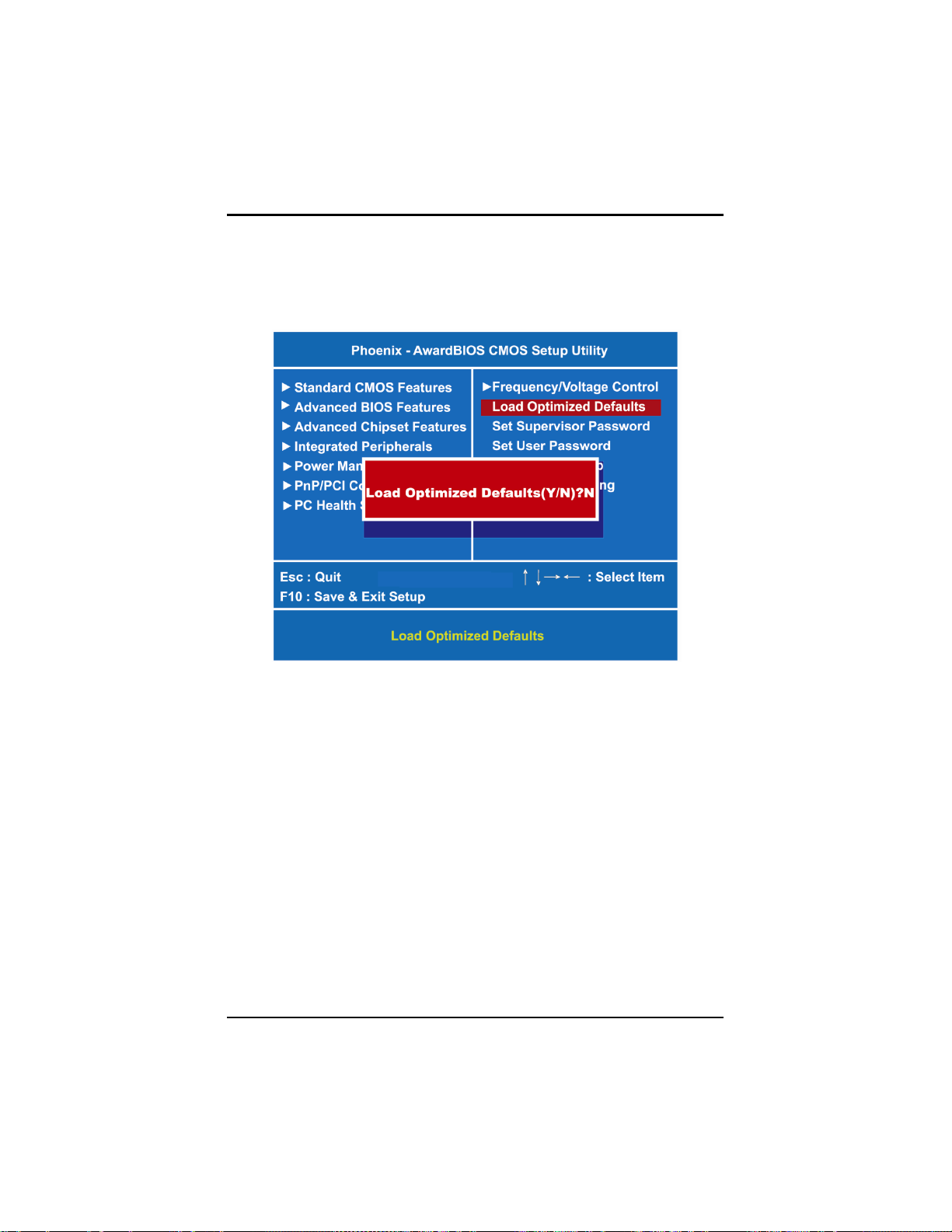
3.12 Load Optimized Defaults
This option allows you to load your system configuration with default
values. These default settings are optimized to enable hi gh
perfo r mance features.
To load CMOS SRAM with SETUP default values, please enter “Y”. If
not, please enter “N”.
42
PHOENIX-AWARD BIOS Setup Utilit y
Page 51

DSA-132 User’s Man ual
3.13 Set Supervisor /U ser P as sw ord
You can set a supervisor or user password, or both of th em. Th e
differ ences between them are:
1. Supervisor password: You can en ter and change the options on
the setup menu.
2. User passwor d: You can just enter, but have no right to change
the options on the setup menu.
When you select th is function, the follo wing message will appear at the
center of the screen to assist you in creating a password .
ENTER PASSWORD
Type a m aximum eight-character password, and pres s <Enter>. This
typed password will cl ear previous l y enter ed pas sword from the CMOS
memory. You will be asked to confirm this password. Type this
password again and press <Enter > . You may also press < Esc> to abort
this selection and not enter a pas sword.
To disable the password, just press <Enter> when you are prompted to
enter a password. A mess age will confirm the p assword is gett ing
disabled. Once the password is disabled, the system will boot and you
can enter Setup freely.
PASSWORD DISABLED
When a pass word is enabled, you have t o type it every time you enter
the Setup. It prevents any unauthorized persons from changing your
system configuration.
Additionally, when a p assword is enabled, you can also r equir e the
BIOS to req uest a password every time th e system r eboots. This wou l d
prevent unauthorized use of your computer.
You decide when the password is required for the BIOS Featu r es
Setup Menu and its Security option. If the Security option i s set to
“System”, the password is required during booting up and entry into the
Setup; if it is set as “Setup”, a pr om pt will only appear before entering
the Setup.
PHOENIX-AWARD BIOS Setup Utilit y
43
Page 52

DSA-132 User’s Manual
3.14 Save & Exit Setup
This section allows you to determine wh ether or not to accept your
modificati ons. Type “Y” to qui t the setup uti lity and save all changes
into the C M OS memory. Type “N” to bring y ou back to the Setup utility.
44
PHOENIX-AWARD BIOS Setup Utilit y
Page 53

DSA-132 User’s Man ual
3.15 Ex i t Without Saving
Select this option to exit the Setup utility without saving changes you
have made in this session. Type “Y”, and it will quit the Setu p util ity
without saving your modific ations . Type “N” to return t o the S etup u tility.
PHOENIX-AWARD BIOS Setup Utilit y
45
Page 54

DSA-132 User’s Manual
CHAPTER 4
DRIVERS INSTALLATION
4.1 System
DSA-132 supports Windows XP and Window 7. To facilitate the
installation of system driver, please carefully read th e instructions in
this chapter before start installing.
1. Insert Intel Express Instal l er Driver CD and s elect t he “\Driver\”.
2. Select your op erating s ys tem dri ver to install.
3. Select all files and follow the installing procedure.
4. Follow the installation step t o r estart the com puter.
NOTE
46
Drivers Installation
Page 55

DSA-132 User’s Man ual
When you have install Window 7 and Graphic driver, You will need to
change the appearance of your display to set up with full screen.
Please r ead carefully and fol low th e below steps to change the d i splay
resolution.
Step 1: Click right button on desktop, and choose “screen r esolution ”
Drivers Installation
47
Page 56

DSA-132 User’s Manual
Step 2: Set “show des ktop only on 1” on Multiple display.
Step 3: And then choose “Mobile PC Display” on Display.
48
Drivers Installation
Page 57

Step 4: Click “Apply”.
DSA-132 User’s Man ual
Step 5: Click “Keep changes”.
Drivers Installation
49
Page 58

DSA-132 User’s Manual
Step 6: And then you can choos e “1920 x 1080”.
50
Drivers Installation
Page 59

Step 7: Finish.
DSA-132 User’s Man ual
Drivers Installation
51
Page 60
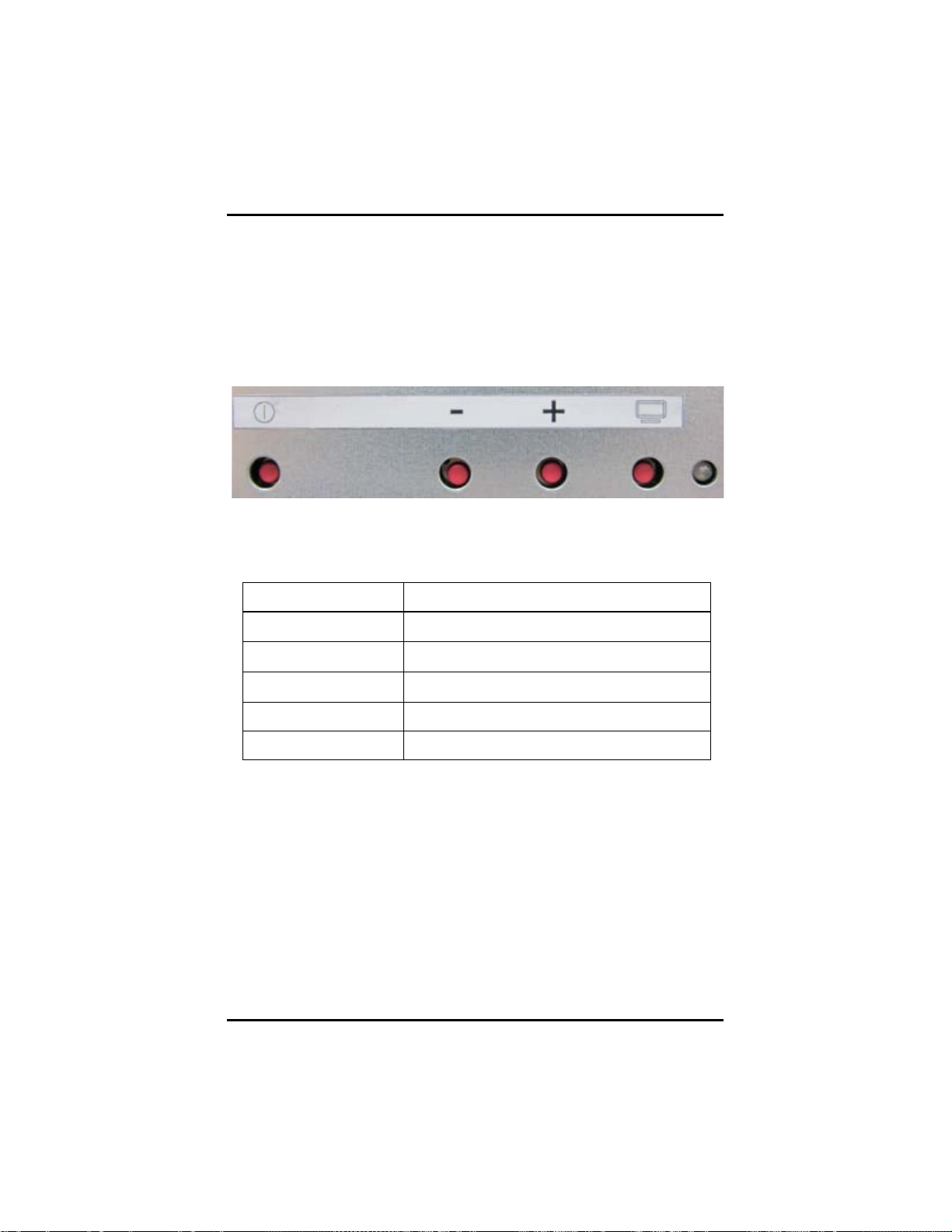
DSA-132 User’s Manual
OSD k ey
Function
POWER
POWER ON / OFF
Monitor
Monitor ON / OFF
Mon itor S t ate
Monitor Power state
CHAPTER 5
OSD Menu
5.1 Hot key
DSA-132 uses OSD to configure brightness, power…etc. You could
configure it via hot key.
Hot key Function Definition
- ADJ-/ SEL-
+ ADJ+/SEL+
52
OSD Menu
 Loading...