

Page 1
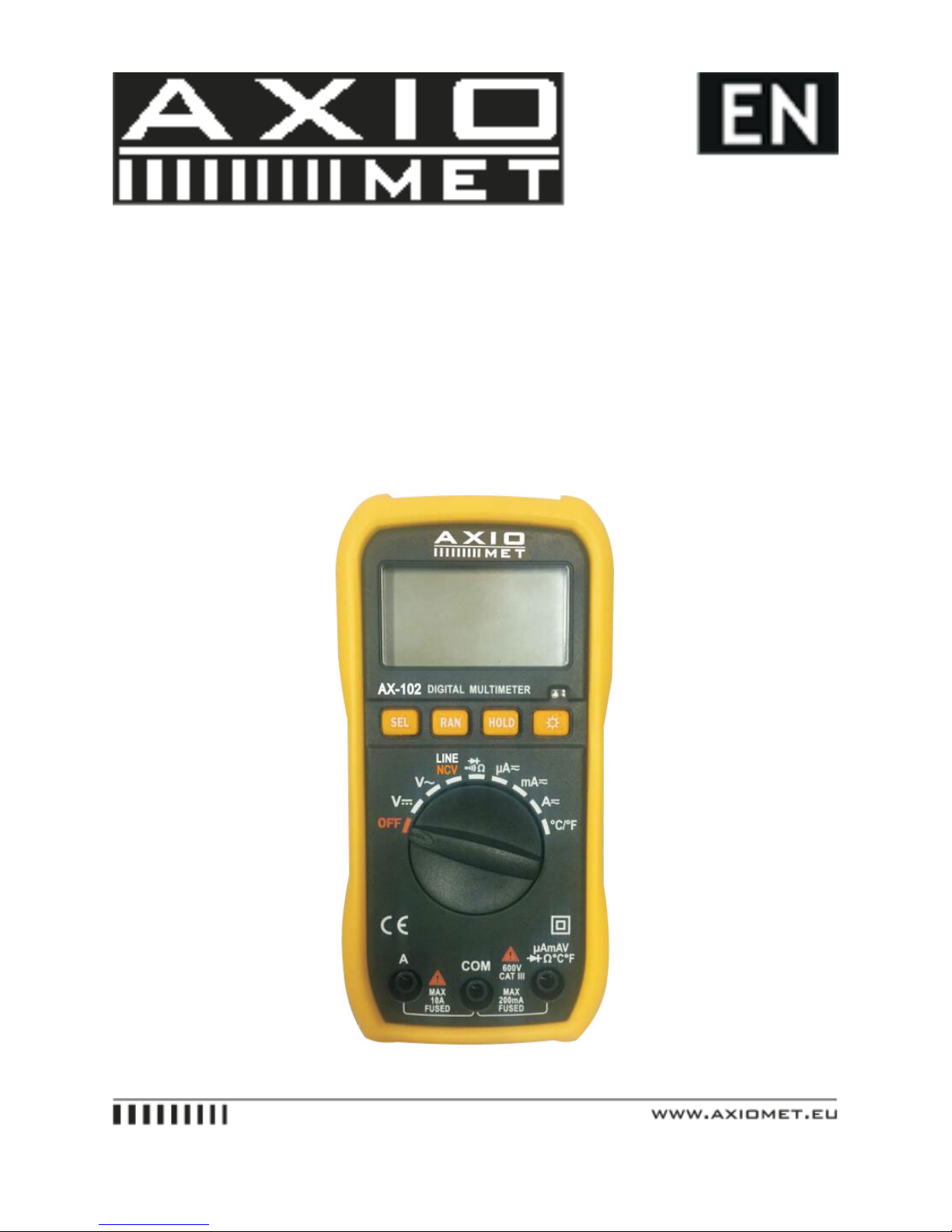
AX-102 - User’s Guide
1.
Page 2

2. INTRODUCTION
Congratulations on your purchase of AX-102 manual range digital multimeter, AX-102 series auto range
digital multimeter. This range meters have been designed as a higher stable, higher reliable and anti-fall
arrest 3 1/2 compact digital multimeter, with equipped 20mm LCD display for easy reading each digit and
with dual integral A/D converter for large scale integrated circuit, as well as over-load protection circuit,
to make this range meters as an excellent durable instrument.
This range meters measure AC/DC Voltage, AC/DC Current, Resistance, Diode Test, Continuity,
Temperature, Battery and Non-Contact Voltage Detection. Proper use and care of this meter will provide
many years of reliable service.
To fully utilize this meter, please keep this manual for reference carefully.
Max. Display//2000 counts
Basic Accuracy//0.5%
DC Voltage Range//200mV-600V
AC Voltage Range//2V-600V
DC Current Range//200µA-10A
AC Current Range//200µA-10A
Resistance(W)//200W-20MW
Temperature (℃)//-20℃-750℃
Temperature (°F)//-4°F-1382°F
Square wave output//NCV (Non-Contact Voltage Detect)//Yes
LINE (Live Wire Recognition)//Yes
Diode Test//Yes
Continuity Check//Yes
Backlit//Yes
Data Hold//Yes
Auto Power Off//Yes
Manual Range//Auto Range//Yes
Power Supply//1.5V x 2
3. SAFETY
This range meters have been designed according to IEC1010 concerning electronic measuring instruments
with 600V CAT III and pollution 2.
Page 3

This symbol indicates that the operator must refer to an explanation in the operating instruction to
avoid personal injury or damage to the meter.
Grounding
High Voltage
Double Insulation
Power Switch
CAUTIONS:
• Improper use of this meter can cause damage, shock, injury or death. Read and understand this user
manual before operating the meter.
• Always remove the test leads before replacing the battery or fuses.
• Inspect the condition of the test leads and the meter itself for any damage before operating the meter.
• Do not measure voltage if the voltage on the terminals exceeds 1000V above earth ground.
• Use great care when making measurements if the voltages are greater 30VAC RMS or 60V DC, these
voltages are considered a shock hazard.
• Always discharge capacitors and remove power from the device under test before performing Diode,
Resistance or Continuity tests.
• To avoid damages to the meter, do not exceed the maximum limits of the input values shown in the
specification.
• In case the device is going to be unused for an extended period of time, remove the batteries to prevent
them from draining.
Page 4
4. PANEL DESCRIPTION
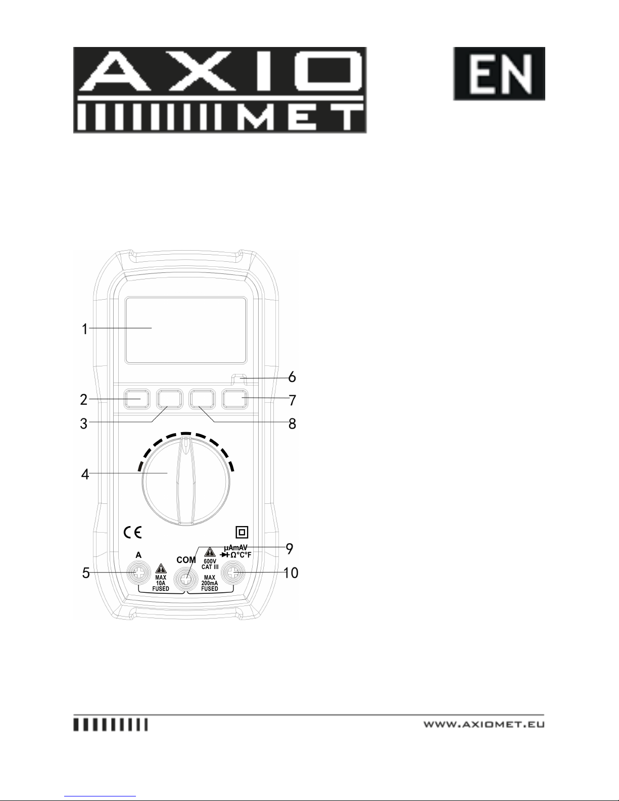
1. LCD display
2. Select Button (shift the measurements of AC, DC current; Temperature, Diode & Continuity check)
3. Range button (Auto/Manual range shift)
4. Rotary switch
Page 5

5. 10A jacks
6. NCV/LINE LED Indicator
7. Backlit button
8. Data hold button
9. COM jack
10. VΩmA Jack
Note: Tilt stand and battery compartment are on rear of unit
5. TECHNICAL SPECIFICATIONS
5.1. General Specifications
� Max display 2000 count digital multimeter
� Overload protection, full range protection
� Data hold function
� Backlit LCD
� Auto power off
� Operating Temperature: 0℃~40℃ (32°F~104°F)
Operating Humidity: < 80%RH
� Storage Temperature: -10℃~60℃ (14°F~122°F)
Storage Humidity: < 70%RH
� Power Supply: 1.5V Battery x 2pcs
� Dimension: 144 x 70 x 32mm
� Weight: Approx. 200g (include battery)
�Accessory: user manual, test leads, gift-box, temperature probe
5.2. Measurement Specifications
5.2.1.
Accuracy: ±(%readings + digit), warranty period: 12 months
Environment temperature: 18℃~28℃; humidity: ≤80%
5.2.2. DC Voltage
Range//Resolution//Accuracy
200mV//100mV//±(0.5% reading + 2 digits)
2V//1mV//±(0.5% reading + 3 digits)
20V//10mV//±(0.8% reading + 3 digits)
Page 6

200V//100mV//
500V//1V//±(0.8% reading + 5 digits)
Overload Protection: 200mV Range at 250V DC or 250V AC RMS
Other ranges at 600V DC or 600V AC RMS
5.2.3. AC Voltage
Range//Resolution//Accuracy
2V//1mV//±(1.0% reading + 10 digits)
20V//10mV//±(1.0% reading + 10 digits)
200V//0.1V//±(1.0% reading + 10 digits)
500V//1V//±(1.0% reading + 10 digits)
600V//1V//±(1.0% reading + 10 digits)
Overload Protection: 600V DC or 600V AC RMS
Frequency range: 40~400Hz
5.2.4. DC Current
Range//Resolution//Accuracy
200µA//0.1µA//±(1.0% reading + 5 digits)
2mA//1µA//±(1.0% reading + 5 digits)
20mA//10µA//±(1.0% reading + 5 digits)
200mA//100µA//±(2.0% reading + 5 digits)
2A//1mA//±(3.0% reading + 5 digits)
10A//10mA//±(3.0% reading + 5 digits)
Overload protection: fuse F200mA/250V
No fuse for 10A range
5.2.5. AC Current
Range//Resolution//Accuracy
200µA//0.1µA//±(1.8% reading + 5 digits)
2mA//1µA//±(1.8% reading + 5 digits)
20mA//10µA//±(1.8% reading + 5 digits)
200mA//100µA//±(2.5% reading + 5 digits)
2A//1mA//±(3.0% reading + 5 digits)
10A//10mA//±(3.0% reading + 5 digits)
Overload protection: fuse F200mA/250V
No fuse for 10A range
Page 7
5.2.6. Resistance
Range//Resolution//Accuracy
200Ω//0.1Ω//±(1.0% reading + 2 digits)
2kΩ//0.001kΩ//±(1.0% reading + 2 digits)
20kΩ//0.01kΩ//±(1.0% reading + 2 digits)
200kΩ//0.1kΩ//±(1.0% reading + 2 digits)
2MΩ//0.001MkΩ//±(1.0% reading + 2 digits)
20MΩ//0.01MΩ//±(1.0% reading + 2 digits)
Overload protection: 250V DC or 250V AC RMS
Maximum open circuit voltage: <3.2V
5.2.7. Diode and Continuity
Range//Function
// Display approximate forward voltage of diode
// Built-in buzzer will be sounded if resistance is less than 70Ω±30Ω
5.2.8. Temperature
Range//Resolution//Accuracy
-20℃ ~ 750℃//1℃//±(1.0% reading + 2 digits)
-4°F ~ 1832°F//1°F//±(1.0% reading + 2 digits)
Overload protection: 250V DC or 250V AC RMS
6. OPERATING INSTRUCTIONS
6.1. AC and DC Voltage Measurement
WARNING:
Risk of electrocution. High-voltage circuits, both AC and DC, are very dangerous and should be measured
with great care.
� To avoid electrical shock and/or damage to the instrument, do not attempt to take any voltage measurement that might exceed 600VDC.
� To avoid electrical shock and/or damage to the instrument, do not apply more than 600VDC between the
common terminal and the earth ground.
1) Set the rotary switch to the voltage position. (V / V~)
2) Insert the black test lead banana plug into the negative COM jack; insert the red test lead banana plug
into the positive V/ΩmA jack.
3) Touch the black test probe tip to the negative side of the circuit; touch the red test probe tip to the
positive side of circuit.
Page 8
4) Read the voltage in the LCD display. The polarity of red test lead connection will be indicated when
making DC Voltage measurement.
NOTE:
Unstable display may occur, especially at the low voltage range measurement, even no test leads insert at
input terminals, if an erroneous readings suspected, short the V/ΩmA jack and COM jack and make sure
the zero displayed at LCD.
6.2. Current Measurement
WARNING:
�To avoid damage to the meter, check the fuse of the meter before current measurement.
� User the proper terminals, function and range for any current measurement
� Never attempt an open circuit potential to earth is greater than 250V, do not place the test leads in
parallel with a circuit or component when the test leads are plugged into the current terminals.
1) Remove the power from the circuit under test and discharge the capacitors of the circuit, set the rotary
switch to current measuring range.
2) Insert black test lead banana plug into the negative COM jack, for current measurement less than
200mA insert the red test lead banana plug into the mA jack, for current measurement between 200mA to
10A insert the red test lead banana plug into 10A jack.
3) Break the circuit under test, connect the black test lead to the more negative side of the break, and
connect the red test lead to the more positive side of break.
4) Turn on the power of circuit under test and read the value in LCD display. If only display OL, which
means the input over range and requested to select the higher range.
5) Turn off the power of circuit under test and discharge all capacitors, remove the test leads and recover
the measured circuit.
6) Set the rotary switch to A~ position and apply the AC current measurement.
6.3. Diode Test and Continuity Check
WARNING:
To avoid electric shock, disconnect power to the unit under test and discharge all capacitors before taking
diode test.
1) Set the rotary switch to position
2) Insert the black test lead banana plug into the negative COM jack, insert the red test lead banana plug
into the positive V ΩmA jack. For HK48 series push the SEL button to shift diode/continuity measurement
3) Place the red test lead on the anode of diode and black test lead on the cathode of diode, the meter will
show the approx. forward voltage of diode, reverse voltage will indicate OL.
Page 9
4) Touch the test probe tips to the circuit or wire you wish to check, the max. value of resistance under
check will be showed in display, if the resistance is less than 70Ω±30Ω, the audible signal will sound.
NOTE:
� In a circuit, a good diode should produce a forward bias reading of voltage, however, the reverse-bias
reading can be variable based on resistance of other pathways between the probe tips.
� To avoid electric shock, never measure continuity on circuits of wires that with voltage.
6.4. Resistance Measurement
WARNING:
To avoid electric shock, disconnect power to the unit under test and discharge all capacitors before taking
any resistance measurements. Remove the batteries and unplug the line cords.
1) Set the rotary switch to the desired resistance range.
2) Insert the black test lead banana plug into the negative COM jack, insert the red test lead banana plug
into the positive V ΩmA jack.
3) Touch the test probe tips across the circuit or part under test. It is best to disconnect one side of the
part under test so the rest of the circuit will not interfere with the resistance reading.
4) Read the resistance in the LCD display
NOTE:
� The measured value of a resistor in a circuit usually is different from the rated value of resistor, it because
the test current of the meter flows through all possible paths between the probe tips.
� In order to ensure the best accuracy in measurement of low resistance, short the test leads before the
measurement and subtract this resistance value of the test leads.
� For high resistance measurement, the meter may take a few seconds to stabilize the readings.
� In the open circuit, the meter display OL to indicate the over range
6.5. Temperature Measurement
WARNING:
To avoid electrical shock, do not perform temperature measurement when the input the voltage exceed
36V DC or 36V ACRMS.
1) Set the rotary switch to ℃°F position, LCD displays values of environmental of temperature.
2) Insert the temperature probe into the input jack, insert red plug of thermo probe into Ω℃°F jack,
black plug of thermo probe into COM jack, making sure to observe the correct polarity.
3) Touch the temperature probe head to the part whose temperature you wish to measure, keep the probe
touching the part under test until the reading stabilizes.
Page 10
4) Read the temperature in the LCD display.
5) Push SEL button to shift the unit of ℃ or °F
6.6. NCV (Non-Contact Voltage) Detection
WARNING:
Due to external interference source, this function may cause wrong voltage detection, the detection result
is for reference only.
Set the rotary switch to NCV position, contact the top part of meter with the circuit under test,
the indicating LED will flash and audible signal will sound.
NOTE:
� The detection result is for reference, do not determine the voltage by NCV detection ONLY.
� Detection may interfere by socket design, insulation thickness and other variable conditions.
� The external interference sources, such as flashlight, motor, etc, may cause the wrong detection.
6.7. LINE (Live Wire Recognition) Test
Set the rotary switch to LINE position, connect the black test lead to COM jack and red test lead to VΩmA
jack, hold the insulation part of black test lead and not put into circuit under measurement; contact the
red test lead to live wire, the buzzer of meter will be activated and red LED will be flickered, when the red
test lead connect the earth line, the buzzer does not sound and LED will not flicker.
NOTE:
When the circuit is in serious leakage (approx. over 15V), the red test lead even contact earth line, the
buzzer of meter will be sounded and LED will be flickered.
6.8. Display Backlit
Press the button for 1 or 2 seconds to turn on or off the display backlit function, the backlight will
automatically turn off after 10 seconds.
7. MAINTENANCE
7.1.
WARNING:
To avoid electric shock, disconnect the test leads from any source of voltage before removing the back cover
or the battery or fuse covers.
Page 11
� To avoid electric shock, do not operate the meter until the battery and fuse covers are in place and fastened
securely.
7.2. Battery Installation
To avoid the false readings, replace the battery as soon as the battery indicator appears.
1) Turn power off and disconnect the test leads from the meter.
2) Open the rear battery cover by using screwdriver.
3) Insert the battery into battery holder, observing the correct polarity.
4) Put the battery cover back in place, secure with the screws.
7.3. Replacing the Fuses
1) Turn power off and disconnect the test leads from the meter.
2) Remove the battery cover and the battery.
3) Remove the screws securing the rear cover.
4) Gently remove the old fuse and install the new fuse into fuse holder.
5) Replace and secure the rear cover, battery and battery cover.
 Loading...