

Page 1
INDUSTRIES LIMITED
SFP SERIES
INSTALLATION, OPERATION AND MAINTENANCE INSTRUCTIONS
Installation Instructions
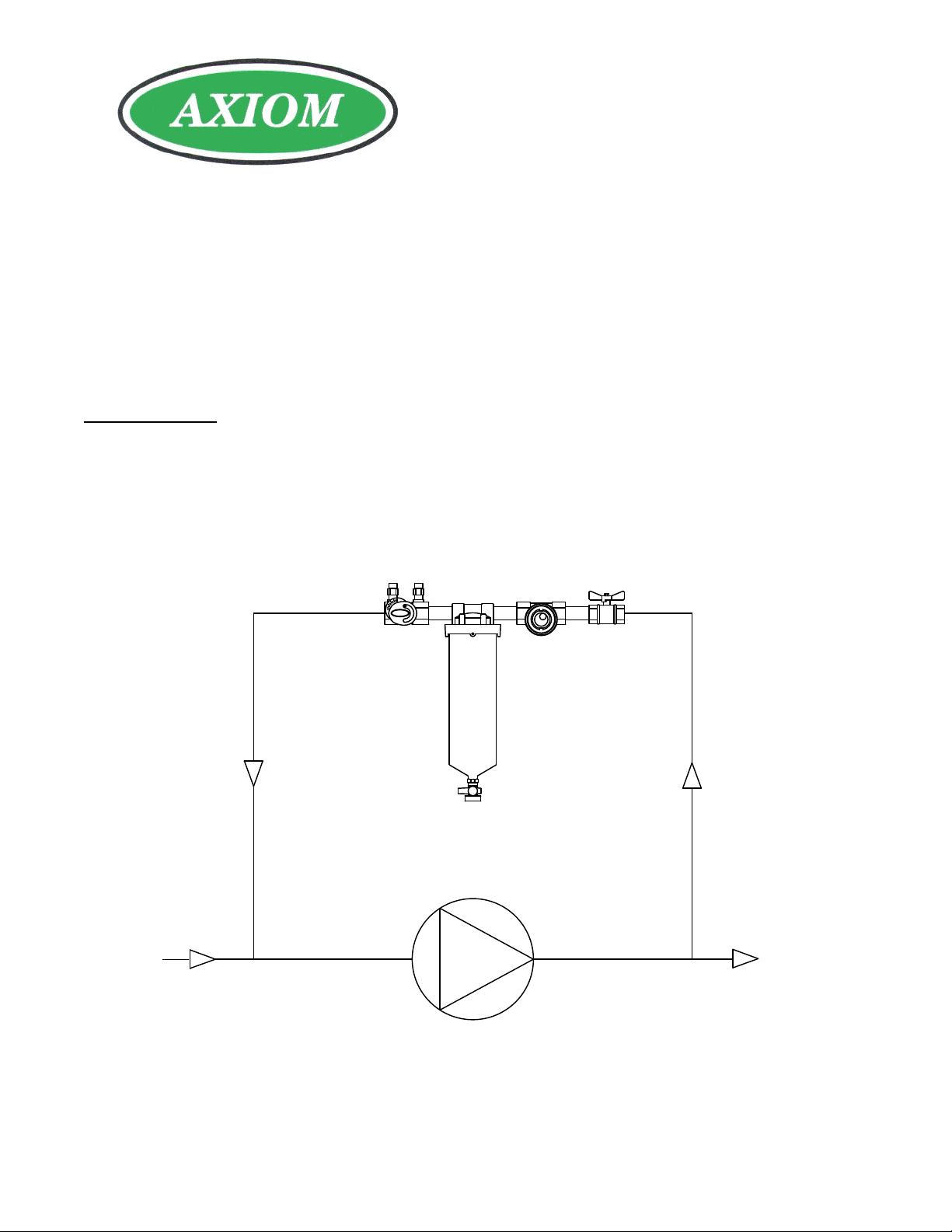
Pipe the side stream filter package in parallel with the pump. Flow should go through the components in the order of:
the isolation ball valve, sight flow indicator, filter housing, and the balancing valve. Ensure there is a straight run of 3”
of piping before and after the balancing valve for accurate metering. Thread the drain valve to the bottom of the filter
housing. See figure 1: Schematic installation diagram.
Installation Instructions
WARNING: The side stream filter package has a pressure rating of 125 psi at 200˚F (860 kPa at 93˚C). It is
compatible with water, propylene glycol, ethylene glycol, methanol (50%), and ethanol (50%). Exceeding these
ratings or using the side stream filter package for uses which it was not intended is dangerous and may void the
warranty. The manufacturer is not responsible for any damages incurred by the side stream filter package being
used in applications that are outside of these specifications.
WARNING: Not for use with potable water
Operation Instructions
Check that all connections have been properly tightened to avoid leaks. Ensure all three valves are closed, open the
manual air vent on the upstream side of the balancing valve body and slowly open the isolation ball valve until all the
air has been purged from the SFP then close the manual air vent.
Use the balancing valve to set the flow rate through the side stream filter (see how to set the flow rate on page 3).
Typically 5-10% of the system flow should go through the filter. If the flow rate going through the side stream filter
package is too high it will deprive the system of flow. Once the correct flow rate has been set tighten the memory stop
on the handle of the balancing valve for quick reference later. For more technical information on maintaining clean
hydronic systems visit www.axiomind.com/side-stream-filter-packages.php.
Small particles will be filtered out of the system by the 25 micron cotton wound filter that comes inside the filter
housing. Fluid quality can be seen through the glass windows of the sight flow indicator and movement of the ball
will give an indication of flow.
Maintenance Instructions
Periodically check the fluid quality by looking into the sight flow indicator. New systems or systems that have been
worked on will have a lot of stuff to clean out and it is usually necessary to change the filters often for the first while.
To replace the filter cartridge close the ball valve and wait for the side stream filter package to reach a safe
temperature. Then close the balancing valve, open the air vent and drain using the valve at the bottom of the filter
2615 Wentz Avenue, Saskatoon, SK S7K 5J1 Ph: (306) 651-1815 Fax: (306) 651-2293
email: [email protected] website: www.axiomind.com © 2013 Axiom Industries Ltd.
Page 2
INDUSTRIES LIMITED
housing. Use the steel tool that comes with the SFP to loosen the filter housing ring. Remove the old filter cartridge
and replace it with a new one. Once the 25 micron filter cartridge (SFP-10-25M or SFP-20-25M) is not picking up
particles it’s time to change to a finer filter (SFP-10-5M, or SFP-20-5M). For finer filter cartridges and replacements
visit your local Axiom distributor.
The glass windows on the sight flow indicator can be replaced. To replace the glass windows close the ball valve and
wait for the side stream filter package to reach room temperature. Then close the balancing valve, open the air vent
and drain using the valve at the bottom of the filter housing. Remove the glass windows from the sight flow indicator.
For replacement seal kits including windows contact your local Axiom distributor.
Limited Warranty
The SFP side stream filter package is warranted against defects in materials and workmanship for one year.
BALANCING
VALVE
SIGHT FLOW
INDICATOR
AXIOM
FILTER
RETURN
Figure 1: Schematic installation diagram of the SFP series side stream filter package mounted across
the pump
SYSTEM
SUPPLY
2615 Wentz Avenue, Saskatoon, SK S7K 5J1 Ph: (306) 651-1815 Fax: (306) 651-2293
email: [email protected] website: www.axiomind.com © 2013 Axiom Industries Ltd.
Page 3
INDUSTRIES LIMITED
Setting the Flow Rate
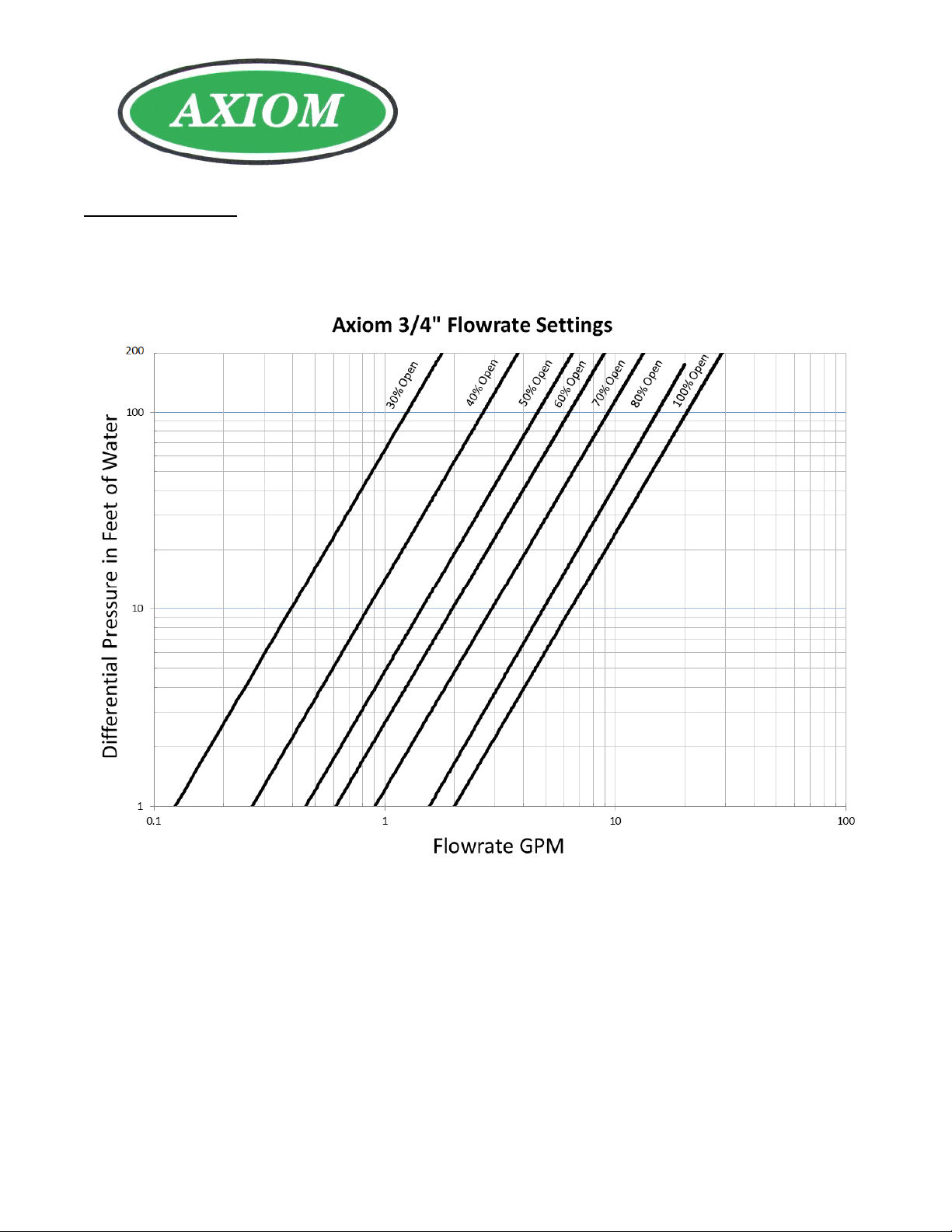
For the ¾” size use figure 2 to find the flow rate through the side stream filter package at various % open
positions of the balancing valve.
Figure 2: Flow rate settings for the ¾” balancing valve.
The 1” balancing valve has a fixed orifice with a constant CV. To calculate the flow through the 1” metering
valve use the formula PSID = (Flow/Cv)2 where CV = 12.2.
2615 Wentz Avenue, Saskatoon, SK S7K 5J1 Ph: (306) 651-1815 Fax: (306) 651-2293
email: [email protected] website: www.axiomind.com © 2013 Axiom Industries Ltd.
Page 4

INDUSTRIES LIMITED
2615 Wentz Avenue, Saskatoon, SK S7K 5J1 Ph: (306) 651-1815 Fax: (306) 651-2293
email: [email protected] website: www.axiomind.com © 2013 Axiom Industries Ltd.
Page 5
INDUSTRIES LIMITED
2
AXIOM
1
8
3
4
2
6
2
7
5
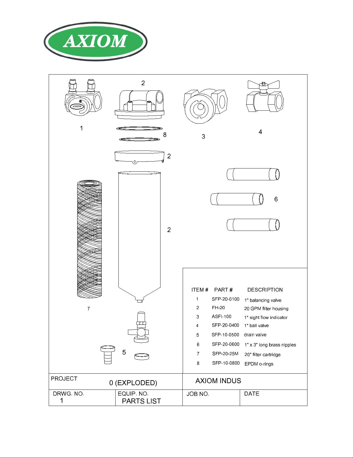
PROJECT
SFP-20 (EXPLODED)
DRWG. NO. EQUIP. NO.
1
PARTS LIST
ITEM #
1
2
3
4
5
6
7
8
AXIOM INDUSTRIES LTD.
JOB NO.
LEGEND
PART #
SFP-20-0100
FH-20
ASFI-100
SFP-20-0400
SFP-10-0500
SFP-20-0600
SFP-20-25M
SFP-10-0800
DESCRIPTION
1" balancing valve
20 GPM filter housing
1" sight flow indicator
1" ball valve
drain valve
1" x 3" long brass nipples
20" filter cartridge
EPDM o-rings
DATE
APRIL 26 2013
2615 Wentz Avenue, Saskatoon, SK S7K 5J1 Ph: (306) 651-1815 Fax: (306) 651-2293
email: [email protected] website: www.axiomind.com © 2013 Axiom Industries Ltd.
 Loading...