

Page 1
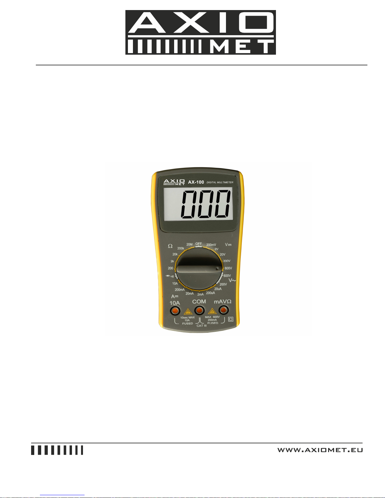
DIGITAL MULTIMETER
AX-100
INSTRUCTION MANUAL
Page 2
1. Safety Notes
1. Do not input a limit value over the range when measuring.
2. When measuring voltage higher than 36V DCV, 25V ACV, check the connection and insulation of
the test leads to avoid electric shock.
3. Keep the test leads away from the testing point when converting function and range.
4. Don’t add voltage to the input terminal when measuring resistance.
2. Technical Features
Accuracy: ± (a%×reading+d)
Surrounding: (23±5), relative humidity<75%. One year warranty since the date of manufacture.
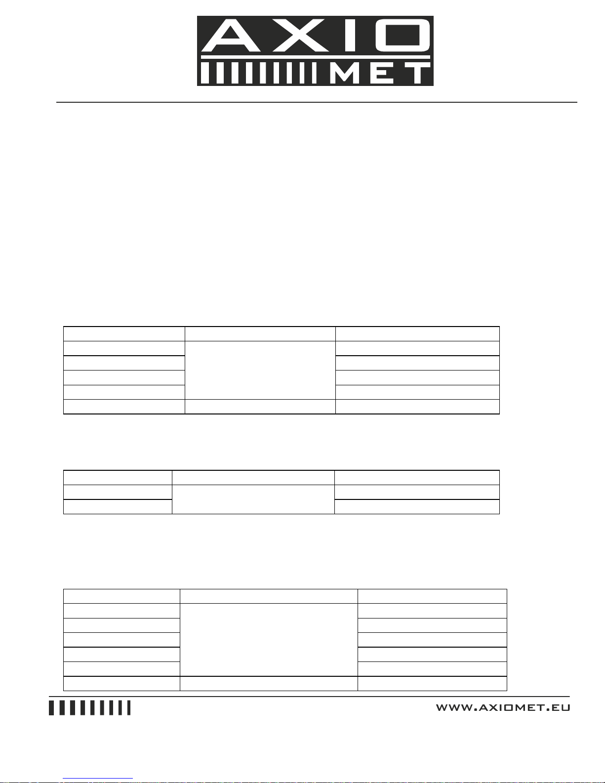
2.1 DCV
Range Accuracy Resolution
200mV 100uV
2V 1mV
20V 10mV
200V
±(0.5%+4)
100mV
600V ±(1.0%+5) 1V
Input impedance: 1MΩfor all ranges.
2.2 ACV
Range Accuracy Resolution
200V 100mV
600V
±(1.2%+10)
1V
Input impedance: 1MΩ.
Frequency Response: (40~200)Hz
2.3 DCA
Range Accuracy Resolution
20uA 0.01uA
200uA 0.1uA
2mA 1uA
20mA 10uA
200mA
±(1.5%+3)
100uA
10A ±(2.0%+5) 10mA
Page 3
Max. Input current: 10A (no more than 6 seconds)
Overload Protection: 0.2A/250V; 10A/250V fuse.
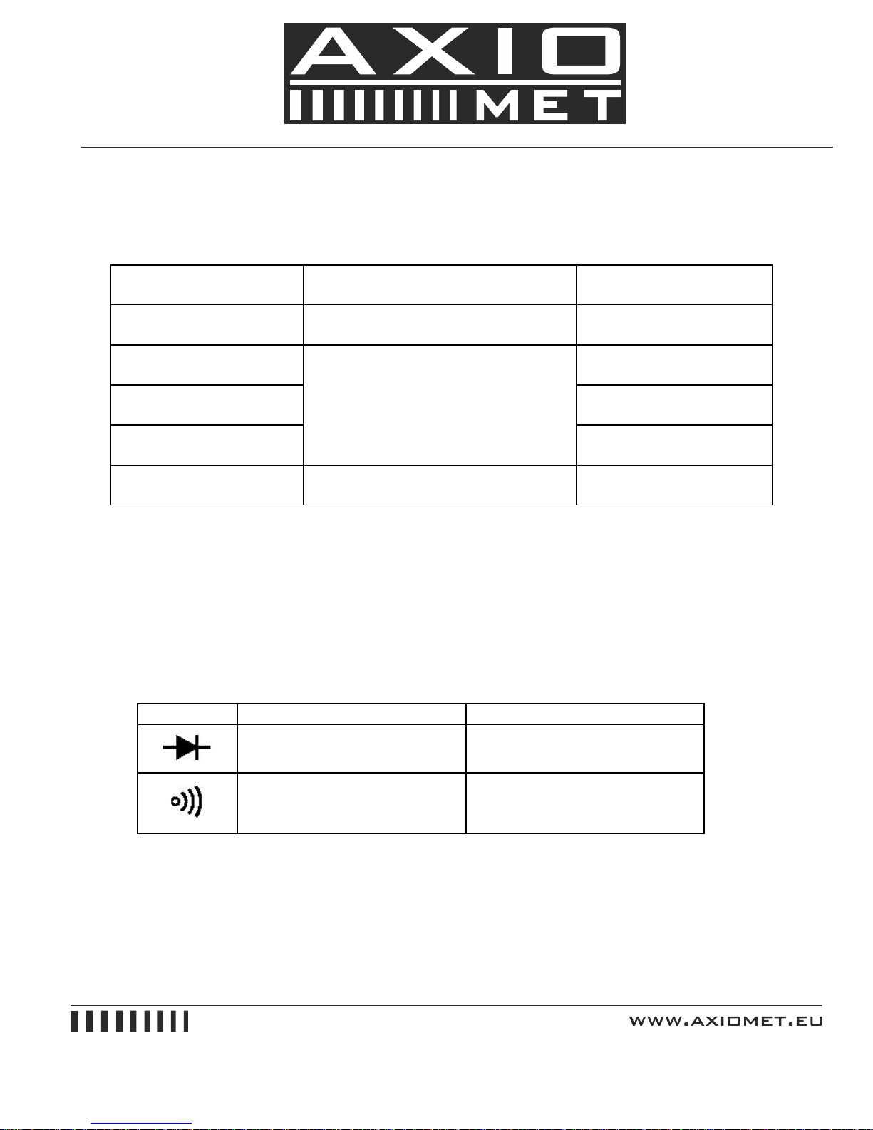
2.4 Resistance
Overload Protection: 250V DC/AC peak value
Note: At range 200Ω, first short-circuit the meter pens to measure the wire resistance. Then subtract it
from the real measurement.
2.5 Diode and continuity test
Range Display Testing Condition
Forward voltage drop of diode
Forward DCA is approx. 1mA,
Backward voltage is apporx.3V
Buzzer makes a long sound
while resistance is less than
(70±20)Ω
Open voltage is approx.3V
Overload Protection: 250V DC/AC peak value
2.6 DC Voltage Measurement
1. Apply the black test lead to "COM" terminal and the red test lead to “V/Ω” terminal.
2. Set the knob to a proper DCV range, and connect the test leads crossly to the electric circuit under
test. LCD displays polarity and voltage under test connected by the red test lead.
Range Accuracy Resolution
200Ω ±(0.8%+5) 0.1Ω
2kΩ 1Ω
20kΩ 10Ω
200kΩ
±(0.8%+3)
100Ω
20MΩ ±(1.0%+15) 10kΩ
Page 4

Note:
1. Firstly, the knob should be set to the highest range if users have no idea about the range of voltage
under test. Then select the proper range based on display value.
2. If MSD displays “1", it means the meter is over range. Please set the knob to a higher range.
3. Do not attempt to input voltage over 600V. Otherwise, it may damage the circuit of the meter.
4. Avoid touching high voltage circuit when measuring it.
2.7 AC Voltage Measurement
1. Apply the black test lead to "COM" terminal and the red test lead to “V/Ω” terminal.
2. Set the knob to a proper ACV range, and connect the test leads crossly to the electric circuit under
test.
Note:
1. Firstly, the knob should be set to the highest range if users have no idea about the range of voltage
under test. Then select the proper range based on display value.
2. If MSD displays “1", it means the meter is over range. Please set the knob to a higher range.
3. Do not attempt to input voltage over 600Vrms. Otherwise, it may damage the circuit of the meter.
4. Avoid touching high voltage circuit when measuring it.
2.8 DC Current Measurement
1. Apply the black test lead to "COM" terminal and the red test lead to “V/Ω” terminal (max. 200mA), or
put the red test lead to "10A" terminal (max. 10A).
2. Set the knob to a proper DCA range, and connect the test leads in series to the electric circuit under
test. LCD displays polarity and current value under test connected by the red test lead.
Note:
1. Firstly, the knob should be set to the highest range if users have no idea about the range of voltage
under test. Then select the proper range based on display value.
2. If MSD displays “1", it means the meter is over range. Please set the knob to a higher range.
3. The max input current is 200mA or 10A (depends on the insert position of the red meter pen).
Excessive current will melt the fuse. When measuring, if the meter has no reading display, please
check relevant fuse.
2.9 Resistance Measurement
1. Apply the black test lead to "COM" terminal and the red test lead to “V/Ω” terminal.
2. Set the knob to a proper resistance range, and connect the leads crossly to the resistance under
test.
Page 5
Note:
1. The LCD displays "1" when the resistance is over the selected range. The knob should be adjusted
to a higher range. When resistance under test is over 1MΩ, the reading shall be stable in a few
seconds, which is a normal status when measuring high resistance.
2. When the input terminal is in open circuit, it displays overload.
3. When measuring in line resistor, be sure that the power is off and all capacitors are released
completely.
4. It is absolutely forbidden to input voltage at the range of resistance, though the meter has voltage
protection function at this range.
2.10 Diode Test
1. Apply the black test lead to "COM" terminal and the red lead to "V/Ω" terminal (the polarity of red
lead is “+”)
2. Set the knob to“ ”range, connect test leads to the diode under test. The red test lead connects
to diode positive polarity and the reading is the approx. value of diode forward voltage drop.
2.11 Continuity Test
Set the knob to“ ”range, apply test leads to the two points of tested circuit. If the inner buzzer
sounds, the resistance is less than (70±20) Ω.
3.Battery Replacement
Note: Pay attention to the battery status.
Please replace the battery when LCD displays “ ” .
Steps:
1. Unscrew the battery cover.
2. Take out the 9V battery and replace it with a new one.
3. Install and screw the battery cover.
Fuse Replacement (This operation could only be processed in power off status.)
1. Unscrew the battery cover.
2. Take out the battery and open the back cover.
3. Please use fuse of the same specification.
The Company shall not be held liable for any accidents and hazards resulted from the maloperations by the user.
The function stated in this operation manual can not be taken as the reason for using the
product for special purposes.
 Loading...