


SZU 21-00
OPERATION INSTRUCTIONS
SAT-Navi
EN – Read and keep

Operation Instructions
SZU 21-00
Safety Notes
Turn off the receiver or any used power supply before installing, to avoid short-
circuit.
Installation and repairs to the equipment may only be carried out by technicians
observing the current VDE guideline s. No liab ility will be assumed in the case of
faulty insta llation and commissioning.
Before opening the device, pull the mains cable or remove the power supply,
otherwise t her e is a danger to life. The same is true when you clean the dev ic e or
perform work on the connections.
Power feeding cables as well as feeder lines may not be damaged or clamped by
objects of any ki nd.
Avoid exposure of the equipment to direct sunlight and to other heat sources (e. g.
radiators. other electrical devices, chimney, etc.). Absolutely avoid that cables come
near any sour ce of hea t (e.g. rad ioa tors , ot her e lectr ical devices, chimne y, etc. )..
© AXING AG • Reserving change in design and type - We cannot be held liable for printing errors 14.04.11
2

Operation Instructions
SZU 21-00
Content
1 Common 4
1.1 Delivery 4
1.2 Description 5
2 Power supply 7
2.1.1 External power supply 7
2.1.2 Satellite receiver 7
2.1.3 Internal batteries 7
3 Operation 8
3.1 Main menu 8
3.1.1 Short Circuit Protection 10
3.2 Light menu 10
3.3 Update menu 11
4 Technical specifications 14
4.1 List of tables 15
4.2 List of illustrat ion s 15
14.04.11 © AXING AG • Reserving change in design and type - We cannot be held liable for printing errors
3

Operation Instructions SZU 21-00
Chapter 1: Common
1 Common
1.1 Delivery
Fig. 1: Delivery
SAT-Navi SZU 21-00
Transparent weather-protection
RS-232 Adapter
Note
Batteries (12xAA) are not included in delivery!
Separately available:
Progra mm ing- Set SZU 22-00, consisting of:
1 x Adapter RS-232 to USB
1 x USB connecting cable
1 x Null-Modem cable
1 x Driver CD ROM
Switch ing mode power supp ly SZU 99-2 2
© AXING AG • Reserving change in design and type - We cannot be held liable for printing errors 14.04.11
4
Operation Instructions SZU 21-00
Chapter 1: Common
1.2 Description
This product is simple and convenient for setting and aligning a satellite dish. Using the
satellite parameters the user can set and align a satellite dish quickly, accurately and
easily.
DC-power
supply
socket
LNB
Multiswitch
SAT-Receiver
ext. power
supply
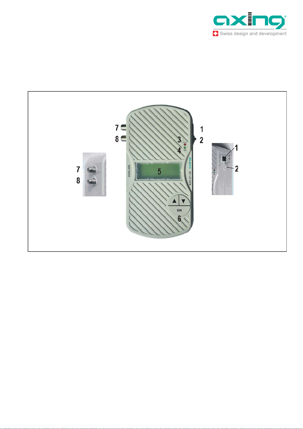
Fig. 2: Inputs, display, buttons
Inputs, display, buttons
1. DC-pow er sup p ly socket
If the SAT-Navi should be operated with an external power supply (which is not
included) plea se co nnect it here.
2. Slide switch
In the upper position, the SAT-Navi will acquire power from the ext ernal power
supply or from tuner power supply input (by a connected receiver). In the lower
position, the SAT-Navi will acquire the power supply from the AA cells in the battery
compartment.
3. Low Voltage LED
The red LED is glowing, when the input voltage is too low (< 13,3 V) or whe n the
batteries are empty.
4. Power LED
The LED is glow ing, wh en t he dev ic e is in operation.
14.04.11 © AXING AG • Reserving change in design and type - We cannot be held liable for printing errors
5

Operation Instructions SZU 21-00
Chapter 1: Common
5. Buttons (,, OK)
To navigate in the software menu
6. LC- Display
Shows menu and additional infor mation.
7. LNB input
Satellite signal input port - connect directly to the LNB.
8. DC power supp ly inp ut
The SAT-Navi can be supplied by a connected power supply (SZU 99-22) or
satellite receiver using this F-socket.
At the bottom side
9
10
Fig. 3: Battery compartment
9. Battery co mp artm ent
Here, you can insert 12 AA (Mignon) batteries or recharg ea b le bat ter ies to pow er
the device ind ep end ently of any power supp ly.
10. RS232 - serial port
Interface used for software updates. (Please see in “Update menu”)
8
7
You will find the port behind the battery flap.
© AXING AG • Reserving change in design and type - We cannot be held liable for printing errors 14.04.11
6
Operation Instructions SZU 21-00
Chapter 2: Power supply
2 Power supply
There are three ways to establish the power supply of the device:
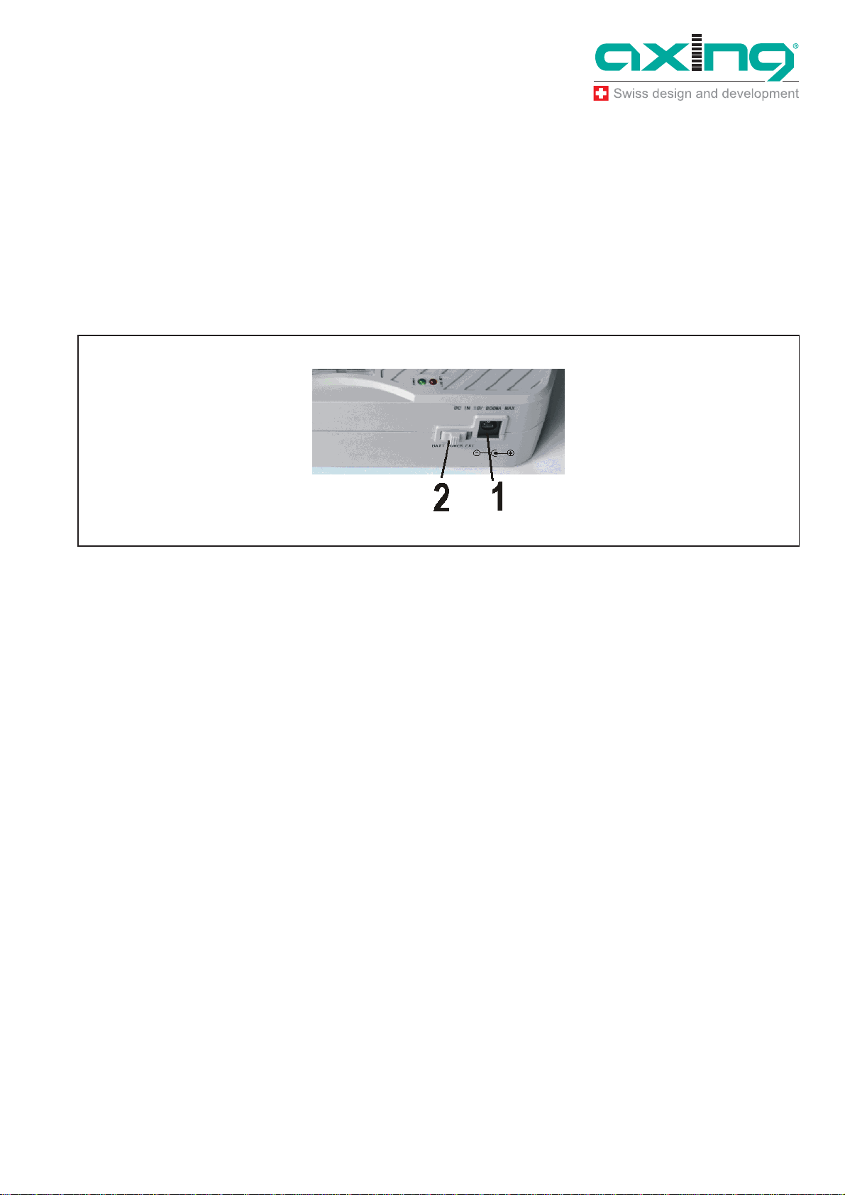
2.1.1 External power supply
Connect the external power supply to the DC-power supply socket (1).
Make sure the slide switch (2) is in the posit ion (“ EX T ”).
Fig. 4: DC-power supply socket (1),slide switch (2)
2.1.2 Satellite receiver
The SAT-Navi can be operated by delivering the power remotely from a satellite
receiver or multiswitch (which may be supposed to be connected to the LNB after
searching the Satellite).
The receiver/multiswitch should be able to deliver 600mA of current to the LNB!
Make sure the power supply selector is in the position (“EXT”).
Connect the LNB/IF input of the satellite receiver to the DC power supply input (8)
of the SAT-Navi
If the SAT-Navi does not power up or switches off when trying to search satellites,
the current delivered by the receiver may be insufficient. Please use another
receiver or anoth er way of supp ly .
2.1.3 Internal batteries
Make sure, you have inserted fitting batteries into the compartment in the right
direction.
Put the Power Supply Selector in the lower position (“BATT”) to activate battery
operation.
Y ou ca n use non -re chargeable and rec har gea ble batteries in AA size.
14.04.11 © AXING AG • Reserving change in design and type - We cannot be held liable for printing errors
7

Operation Instructions SZU 21-00
Chapter 3: Operation
Low Voltage
If the voltage of any power source is lower than 13.3V, the red low voltage LED
lights up
Take care, that the input voltage is always higher than 13.3V.
If you are using rechargeable batteries, switch off (to “EXT”) the device when the
red LED lights up to prevent the cells from total discharge.
3 Operation
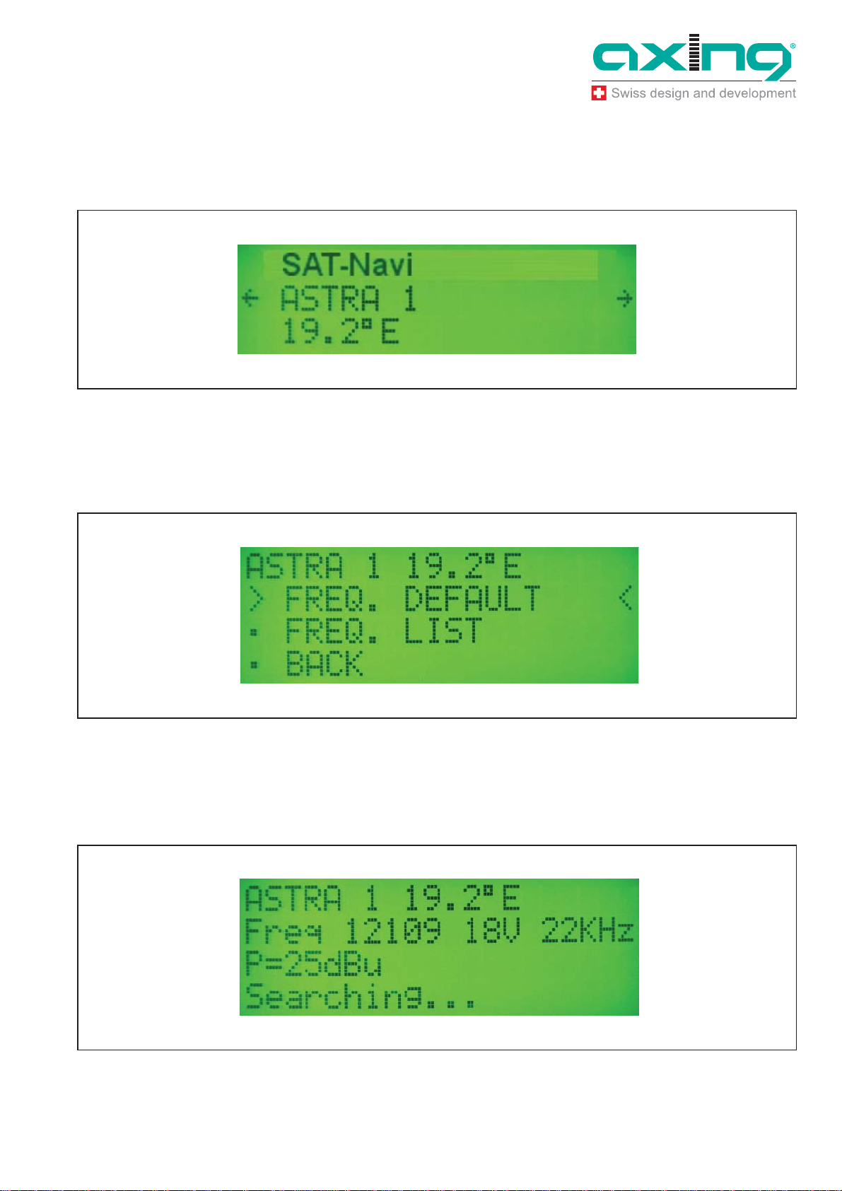
3.1 Main menu
At power on, the display shows version information of the software, and then appears
the main menu.
Fig. 5: Main menu
With the buttons /, you can choose the following options :
SAT-Navi (to align the satellite dish to a desired satellite)
Light (toggle the LCD background light)
Update (to initiate the software update by the USB Adapter)
© AXING AG • Reserving change in design and type - We cannot be held liable for printing errors 14.04.11
8
Operation Instructions SZU 21-00
Chapter 3: Operation
SAT-Navi menu
To align a satellite dish, please take the following steps:
1. Select a satellite from the list
Fig. 6: SAT-Nav menu
2. Choose if you want to search the satellite with the default transponder (FREQ.
DEFAULT) or with other transponders (FREQ. LIST). Please prefer (FREQ.
DEFAULT), because the identification of the satellite is more precise for this option.
Fig. 7: Transponder
Î If you choose (FREQ. LIST), you can select the transponder in the following menu .
Now, the Satellite and Transponder is chosen and the device tries to lock on a signal
from the desired satellite.
Fig. 8: Searching of a signal
14.04.11 © AXING AG • Reserving change in design and type - We cannot be held liable for printing errors
9

Operation Instructions SZU 21-00
Chapter 3: Operation
3. Please move now the Satellite dish antenna slowly until you clearly hear the buzzer
noise. The SAT Navi has logged-in and reckognized the wanted Satellite. The
following other informations are displayed now too:
P: Signal Strength (in dBµV)
BER: Bit Err or Rate
Q: Signal Quality (Bar Graph)
Fig. 9: Signal
With this Information and the acoustic signal, you can fine-tune the antenna to the
opti ma l po s it i on.
The frequency of the acoustic signal is linked to the signal quality. So you can search
the satellite and fine-tune the position also without seeing the display of the Sat
Navigator.
Î To ex it the Sate llite Nav iga tor function, just press OK.
3.1.1 Short Circuit Protection
If there is a short circuit on the LNB input, the LNB power will be cut off and there will be
the messa ge “Sh ort c. detected” in the display .
After you have removed the cause for the short circuit, it appears the message “Short c.
restored” an d the LNB Power is switched on again.
3.2 Light menu
In the Light Menu, you can switch the background light of the LCD on or off.
© AXING AG • Reserving change in design and type - We cannot be held liable for printing errors 14.04.11
10
Operation Instructions SZU 21-00
A
Chapter 3: Operation
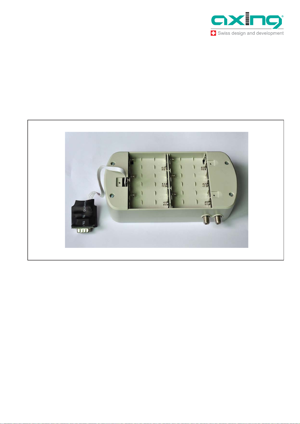
3.3 Update menu
For always being up to dat e, t her e is a possibility to update the software of the Satellite
Navigat or by a serial (RS-232) interfa ce. Since most mode rn PCs don ’t ha ve a RS-232
port a ny more, an adapter to USB ha s to be used.
To update the software, please do the following steps:
1. Connect the update adapter to the Satellite Navigator at the connector found in the
battery compartment (see pict ure )..
RS-232-
dapter
Fig. 10: RS-232-Adapter
2. Connect the update adapter to the USB adapter with the connection cable.
14.04.11 © AXING AG • Reserving change in design and type - We cannot be held liable for printing errors
11

Operation Instructions SZU 21-00
Chapter 3: Operation
Fig. 11: Null modem cable and USB adapter
3. Connect the USB adapter to your PC.
4. Start the software update application on your PC and choose the right COM-Port.
If you are not sure, which COM-Port to choose, under Windows you can find out the
right port in the device manager.
5. Press “Sen d ” on the up date tool.
6. Power on the Sat e llit e Nav igat or and choose “Update” fr om the ma in menu.
The Sate llite Nav igator begins to download , this w ill tak es some m inutes . After the
update, the softw are is bur ne d into t he inte rna l fl ash me mo ry.
DO NOT SWITCH OFF WHILE THE SOFTWARE IS BURNING!
If the update was not successful, there might be the following reasons:
1. The commun ication between the Satellite Navigat or and the upda te application
failed.
Fig. 12: Time out
Î please check the connections and make sure you have selected the right COM port.
2. You try to update wit h the sa me version, which is alrea dy on the device.
© AXING AG • Reserving change in design and type - We cannot be held liable for printing errors 14.04.11
12

Operation Instructions SZU 21-00
Chapter 3: Operation
Fig. 13: Update cancelled
There will also be the message “The STB is up to date!” in that case.
14.04.11 © AXING AG • Reserving change in design and type - We cannot be held liable for printing errors
13

Operation Instructions SZU 21-00
Chapter 4: Technical specifications
4 Technical specifications
Frequency range 950…2150 MHz
RF connecters F female
Operat ing vo lt ag e 13...19 VD C
Current consumption 300mA
Tab. 1: Data sheet
© AXING AG • Reserving change in design and type - We cannot be held liable for printing errors 14.04.11
14

Operation Instructions SZU 21-00
Chapter 4: Technical specifications
4.1 List of tables
Tab. 1: Data sheet 14
4.2 List of illustrations
Fig. 1: Delivery 4
Fig. 2: Inputs, d isp lay, butt ons 5
Fig. 3: Battery co mp artm ent 6
Fig. 4: DC-power sup ply socket (1),slide sw itch (2) 7
Fig. 5: Main menu 8
Fig. 6: SAT-Nav menu 9
Fig. 7: Transp ond er 9
Fig. 8: Search ing of a signal 9
Fig. 9: Signal 10
Fig. 10: RS-232-Adapter 11
Fig. 11: Null modem cable and USB adapter 12
Fig. 12: Ti me out 12
Fig. 13: Update cancelled 13
14.04.11 © AXING AG • Reserving change in design and type - We cannot be held liable for printing errors
15
Operation Instructions SZU 21-00
Chapter 4: Technical specifications
© AXING AG • Reserving change in design and type - We cannot be held liable for printing errors 14.04.11
16
 Loading...