

Page 1
S
U
00
Z
OPERATING INSTRUCTIONS
SAT NAVI
21-
Page 2

Operation Instructions
SZU 21-00
Safety Notes
Turn off the receiver or any used power supply before installing, to avoid short-circuit.
Installation and repairs to the equipment may only be carried out by technicians observing the current
VDE guidelines. No liability will be assumed in the case of faulty installation and commissioning.
Before opening the device, pull the mains cable or remove the power supply, otherwise there is a
danger to life. The same is true when you clean the device or perform work on the connections.
Power feeding cables as well as feeder lines may not be damaged or clamped by objects of any kind.
Avoid exposure of the equipment to direct sunlight and to other heat sources (e. g. radiators. other
electrical devices, chimney, etc.). Absolutely avoid that cables come near any source of heat (e.g.
radioators, other electrical devices, chimney, etc.)..
2 © AXING AG • Reserving change in design and type - We cannot be held liable for printing errors 2014-08-29
Page 3

Operation Instructions
SZU 21-00
Content
1 Common ............................................................................................................................................ 4
1.1 Delivery ................................................................................................................................ 4
1.2 Description ........................................................................................................................... 4
2 Power supply .................................................................................................................................... 6
2.1.1 External power supply ..................................................................................... 6
2.1.2 Satellite receiver .............................................................................................. 6
2.1.3 Internal batteries .............................................................................................. 6
3 Operation ........................................................................................................................................... 7
3.1 Main menu ........................................................................................................................... 7
3.2 SAT-Navi menu ................................................................................................................... 7
3.2.1 BER – bit error rate .......................................................................................... 8
3.2.2 Signal level ...................................................................................................... 8
3.2.3 Short Circuit Protection .................................................................................... 8
3.3 Activating the DiSEqC control .............................................................................................. 8
3.4 Light menu ........................................................................................................................... 9
4 Update................................................................................................................................................ 9
4.1 Connecting the SAT-Navi to the PC .................................................................................... 9
4.2 Preparations ...................................................................................................................... 10
4.3 Firmware update ................................................................................................................ 10
4.4 Updating the satellite and transponder data ...................................................................... 11
4.5 Editing satellite and transponder lists ................................................................................ 12
4.5.1 Editing satellite positions:............................................................................... 12
4.5.2 Editing transponders: ..................................................................................... 13
4.5.3 Closing and saving data ................................................................................ 15
5 Technical specifications ................................................................................................................ 15
29.08.14 © AXING AG • Reserving change in design and type - We cannot be held liable for printing errors
3
Page 4
Operation Instructions SZU 21-00
2:
r
y
Chapter 1: Common
1 Common
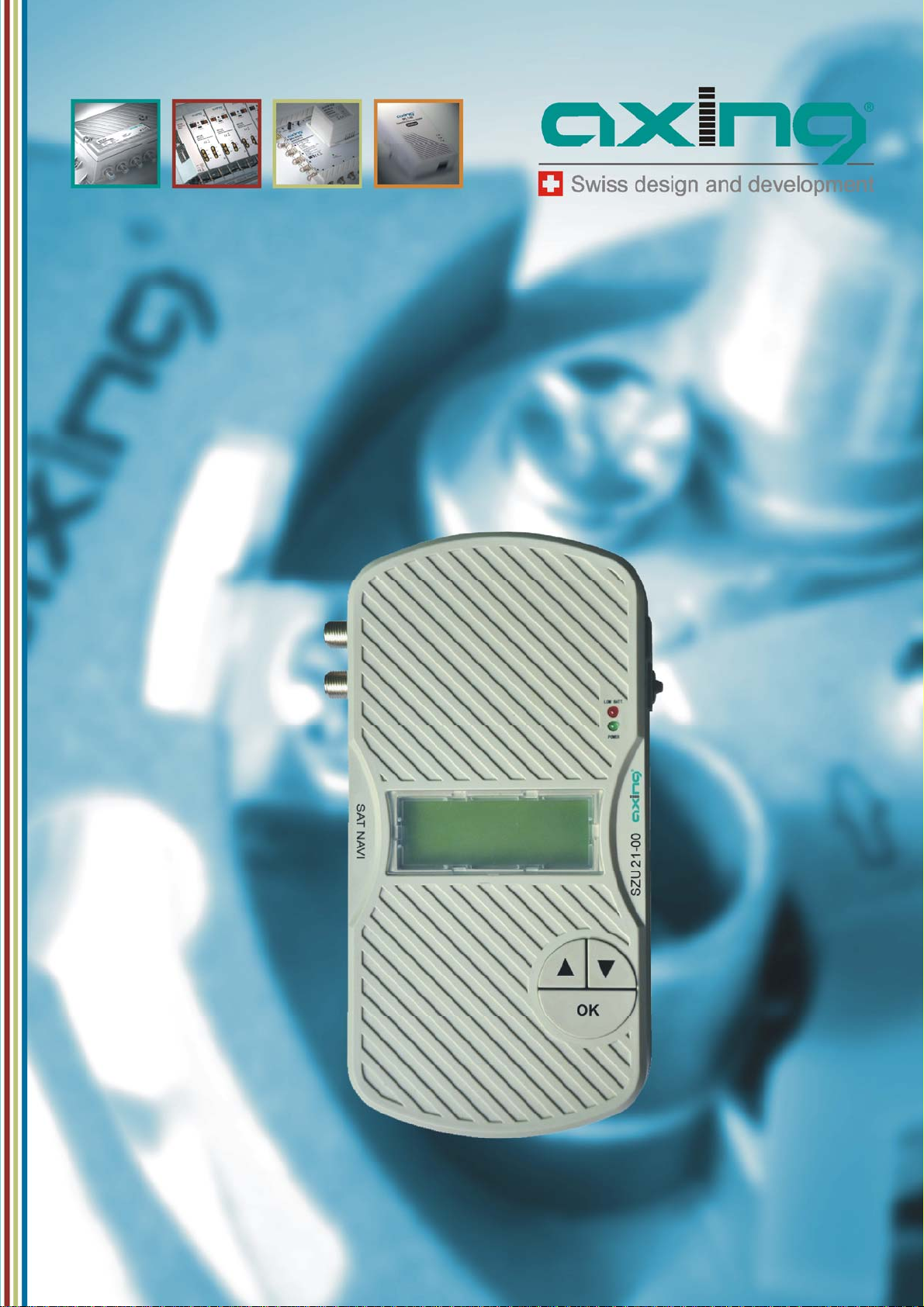
1.1 Delivery
Fig. 1:
Delivery
SAT-Navi SZU 21-00
Transparent weather-protection
RS-232 Adapter
Inputs, display, buttons
Fig.
Note
Batteries (12xAA) are not included in delivery!
Separately available:
Programming-Set SZU 22-00, consisting of:
1 x Adapter RS-232 to USB
1 x USB connecting cable
1 x Null-Modem cable
1 x Driver CD ROM
Switching mode power supply SZU 99-22
1.2 Description
This product is simple and convenient for setting and aligning a satellite dish. Using the satellite
parameters the user can set and align a satellite dish quickly, accurately and easily.
DC-power supply socket
LNB
Multiswitch
SAT-Receive
ext. power suppl
4 © AXING AG • Reserving change in design and type - We cannot be held liable for printing errors 2014-08-29
Page 5

Operation Instructions SZU 21-00
3:
10
Chapter 1: Common
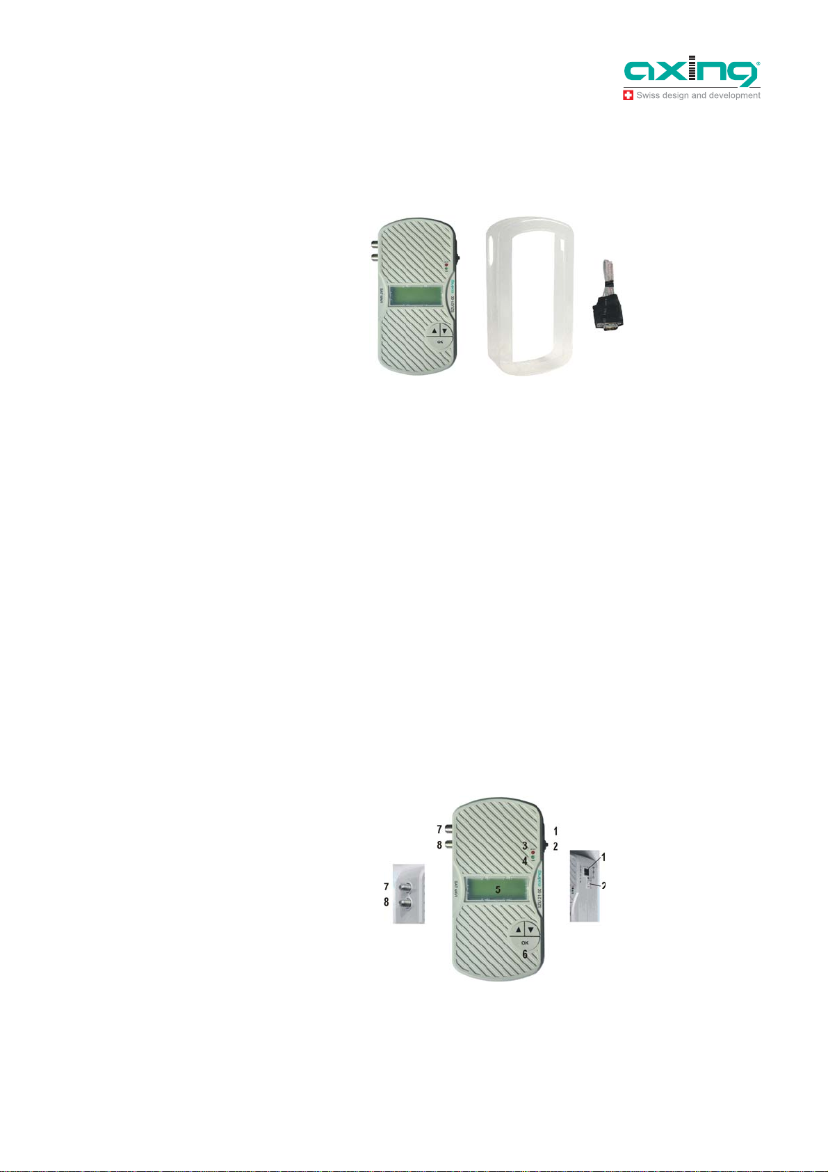
Inputs, display, buttons
1. DC-power supply socket
If the SAT-Navi should be operated with an external power supply (which is not included) please
connect it here.
2. Slide switch
In the upper position, the SAT-Navi will acquire power from the external power supply or from tuner
power supply input (by a connected receiver). In the lower position, the SAT-Navi will acquire the
power supply from the AA cells in the battery compartment.
3. Low Voltage LED
The red LED is glowing, when the input voltage is too low (< 13,3 V) or when the batteries are empty.
4. Power LED
The LED is glowing, when the device is in operation.
5. LC- Display
Shows menu and additional information.
6. Buttons (,, OK)
To navigate in the software menu
7. LNB input
Satellite signal input port - connect directly to the LNB.
8. DC power supply input
The SAT-Navi can be supplied by a connected power supply (SZU 99-22) or satellite receiver using
this F-socket.
Fig.
Battery compartment
At the bottom side
9
8
7
9. Battery compartment
Here, you can insert 12 AA (Mignon) batteries or rechargeable batteries to power the device
independently of any power supply.
10. RS232 - serial port
Interface used for software updates. (Please see in “Update menu”)
You will find the port behind the battery flap.
29.08.14 © AXING AG • Reserving change in design and type - We cannot be held liable for printing errors
5
Page 6

Operation Instructions SZU 21-00
-
p
Chapter 2: Power supply
2 Power supply
There are three ways to establish the power supply of the device:
2.1.1 External power supply
Connect the external power supply to the DC-power supply socket (1).
Make sure the slide switch (2) is in the position (“EXT”).
Fig. 4: DC
(1),slide switch (2)
ower supply socket
2.1.2 Satellite receiver
The SAT-Navi can be operated by delivering the power remotely from a satellite receiver or
multiswitch (which may be supposed to be connected to the LNB after searching the Satellite).
The receiver/multiswitch should be able to deliver 600mA of current to the LNB!
Make sure the power supply selector is in the position (“EXT”).
Connect the LNB/IF input of the satellite receiver to the DC power supply input (8) of the SAT-Navi
If the SAT-Navi does not power up or switches off when trying to search satellites, the current
delivered by the receiver may be insufficient. Please use another receiver or another way of supply.
2.1.3 Internal batteries
Make sure, you have inserted fitting batteries into the compartment in the right direction.
Put the Power Supply Selector in the lower position (“BATT”) to activate battery operation.
You can use non-rechargeable and rechargeable batteries in AA size.
Low Voltage
If the voltage of any power source is lower than 13.3V, the red low voltage LED lights up
Take care, that the input voltage is always higher than 13.3V.
If you are using rechargeable batteries, switch off (to “EXT”) the device when the red LED lights up to
prevent the cells from total discharge.
6 © AXING AG • Reserving change in design and type - We cannot be held liable for printing errors 2014-08-29
Page 7

Operation Instructions SZU 21-00
5:
6:
8:
Chapter 3: Operation
3 Operation
3.1 Main menu
At power on, the display shows version information of the software, and then appears the main menu.
Fig.
Main menu
With the buttons /, you can choose the following options:
SAT-Navi (to align the satellite dish to a desired satellite)
Light (toggle the LCD background light)
Update (to initiate the software update by the USB Adapter)
Confirm your choice by pressing the OK button.
SAT-Nav menu
Fig.
Fig. 7:
Transponder
Fig.
Searching of a signal
3.2 SAT-Navi menu
To align a satellite dish, please take the following steps:
1. Select a satellite from the list
2. Choose if you want to search the satellite with the default transponder (FREQ. DEFAULT) or with
other transponders (FREQ. LIST). Please prefer (FREQ. DEFAULT), because the identification of the
satellite is more precise for this option.
If you choose (FREQ. LIST), you can select the transponder in the following menu .
Now, the Satellite and Transponder is chosen and the device tries to lock on a signal from the desired
satellite.
29.08.14 © AXING AG • Reserving change in design and type - We cannot be held liable for printing errors
7
Page 8

Operation Instructions SZU 21-00
12:
Chapter 3: Operation
3. Please move now the Satellite dish antenna slowly until you clearly hear the buzzer noise. The SAT
Navi has logged-in and reckognized the wanted Satellite. The following other informations are
displayed now too:
P: Signal Strength (in dBµV)
BER: Bit Error Rate
Q: Signal Quality (Bar Graph)
Fig. 9:
Signal
Abb.
10:
bit error rate
With this Information and the acoustic signal, you can fine-tune the antenna to the optimal position.
The frequency of the acoustic signal is linked to the signal quality. So you can search the satellite and
fine-tune the position also without seeing the display of the Sat Navigator.
To exit the Satellite Navigator function, just press OK.
3.2.1 BER – bit error rate
The BER (bit error rate) indicates the system reserves of a Satellite dish unit. The BER value should be
as high as possible.
good acceptable bad
1.0 e-8...e-7
1.0 e-6...e-4
The lowest BER-limit value lies at 2.00e-04, in order to achieve an error-free signal. However with this
a.m. limit-value the system does not have any more reserves and should therefore lie well above this
min. level.
2.0 e-4
1.0 e-3...e-1
3.2.2 Signal level
Abb.
11:
Signal level measured at
an antenna wall outlet
46 dBµV 78 dBµV47...50 dBµV
51...74 dBµV
75...77 dBµV
bad bad good acceptable acceptable
The signal level must neither be too low, nor too high.
3.2.3 Short Circuit Protection
If there is a short circuit on the LNB input, the LNB power will be cut off and there will be the message
“Short c. detected” in the display.
After you have removed the cause for the short circuit, it appears the message “Short c. restored” and the
LNB Power is switched on again.
3.3 Activating the DiSEqC control
If necessary, the respective LNB can be activated via DiSEqC.
Calling up the DiSEqC
Fig.
menu
8 © AXING AG • Reserving change in design and type - We cannot be held liable for printing errors 2014-08-29
Page 9

Operation Instructions SZU 21-00
RS
-
r
Chapter 4: Update
In the main menu, use button to select the menu item DiSEqC 1.0 and press OK to confirm.
Fig. 13:
Selecting an LNB
…
In the DiSEqC 1.0 menu, activate the desired LNB (LNB A to LNB D) by pressing buttons and .
Return to the main menu by pressing the OK button.
Then select a satellite and start search via the SAT-Navi menu.
Note
After switching off the SZU 21-00, the DiSEqC control is deactivated again.
4 Update
Fig. 14:
232 adapter
3.4 Light menu
In the Light Menu, you can switch the background light of the LCD on or off.
For always being up to date, a software update of the SAT-Navi can be carried out via the serial RS-232
interface. Since most modern PCs don’t have an RS-232 port any more, a USB adapter has to be used. It
is included in the programming set SZU 22-00 (the programming set must be ordered separately).
4.1 Connecting the SAT-Navi to the PC
To update the software, the following steps are required:
4. Connect the adapter to the update port of the SAT-Navi located in the battery compartment.
RS-232
adapte
5. Connect the update adapter to the USB adapter via a null modem cable.
29.08.14 © AXING AG • Reserving change in design and type - We cannot be held liable for printing errors
9
Page 10

Operation Instructions SZU 21-00
Chapter 4: Update
Fig. 15:
Null modem cable and
USB adapter
6. Connect the USB adapter to the PC.
4.2 Preparations
Open/extract the SAT NAVI Editor_120313.7z file (it can be a newer version)
Copy the smg folder from SAT NAVI Editor_120313 directly to the C: drive
You will find the following programs in the smg folder
serial _1.0.95.exe
The current version of the firmware (it can be a newer version)
Satfinder Serial.exe
Update software of the satellite and transponder data
SatfinderResourcesEditor.exe
Program for changing/complementing the satellite and transponder data
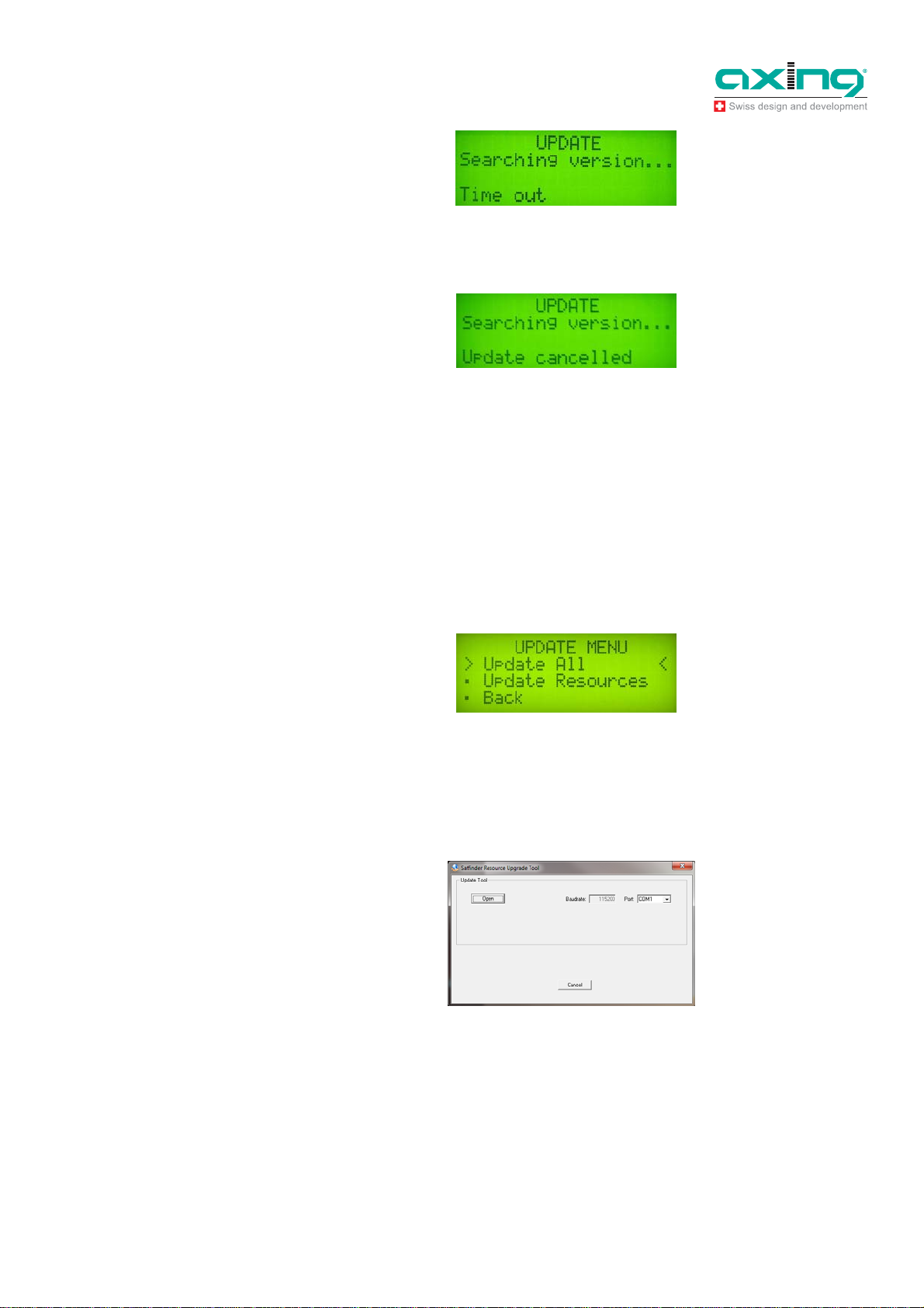
Fig. 16:
Update menu
Note
Note
4.3 Firmware update
Connect the PC and the SZU 21-00 to the programming set SZU 22-00 (see 4.1 on page 9).
Switch on the SAT-Navi and select Update in the main menu.
Under the menu item Update, the menu itemsUpdate ALL and Update Resources will appear.
For a firmware update, select Update ALL and press OK to confirm.
Double-click serial _1.0.95.exe (it can be a newer version) to start iton the PC and select the COM
port that is connected to the SAT-Navi.
If you don’t know which COM port is used, you can find the right COM port under Windows in the
Device Manager.
Click Send button in the update program on the PC to start the transmission.
The SAT-Navi starts the download, which may take a few minutes. After that, the software is written to
the internal flash memory.
Do not switch off the device during the writing process!
The display will show the message "The STB is up-to-date!".
Problems that may arise during the firmware update
An update failure may be caused by the following reasons:
7. Communication between the SAT-Navi and the update application has failed.
Fig. 17:
Time out
10 © AXING AG • Reserving change in design and type - We cannot be held liable for printing errors 2014-08-29
Page 11
Operation Instructions SZU 21-00
Chapter 4: Update
Check the connection and verify whether the right COM port is used.
8. The update is made with a version of the software that is already installed on the SAT-Navi.
Fig. 18:
Update cancelled
Fig. 19:
Update menu of the
SZU 21-00
Fig.
20:
Display of the Satfinder
Serial.exe on the PC
Note
In this case, the display will show the message "The STB is up-to-date!".
4.4 Updating the satellite and transponder data
To transfer the changed satellite and transponder data to the SAT-Navi SZU 21-00, the SZU 21-00 must
be updated to the current firmware version serial _1.0.95 or a newer version.
The new satellite and transponder data are installed on the SZU 21-00 by means of the Satfinder
Resource Upgrade software.
Connect the PC and the SZU 21-00 to the programming set SZU 22-00 (see 4.1 on page 9).
Switch on the SAT-Navi and select Update in the main menu.
Under the menu item "Update", menu items Update ALL and Update Resources will appear.
For a satellite and transponder data update, select Update Resources and press OK to confirm.
Double-click Satfinder Serial.exe to start the program on the PC.
Select the correct COM port in the Port field and open the smg folder by pressing the Open button.
Select the romimageSatfinder.bin file and click Send.
Fig. 21:
Display during the file
transfer
29.08.14 © AXING AG • Reserving change in design and type - We cannot be held liable for printing errors
11
Page 12

Operation Instructions SZU 21-00
Chapter 4: Update
The satellite and transponder lists are transferred. The progress is shown in the lower part of the window.
Fig. 22:
The file was transferred
successfully
Note
Do not switch off the device during the writing process!
Note
4.4.1 Editing satellite and transponder lists
You can find current satellite positions and transponder data, e.g., on the Internet at www.kingofsat.net or
www.lynsat.com.
The satellite and transponder lists are edited by means of the SatfinderResourcesEditor software.
Start the SatfinderResourcesEditor.exe software.
The program’s interface contains two menu items.
Satellite List:
In the satellite list, satellite positions are added, deleted, sorted or changed.
Tranponder List:
In the transponder list, transponders are added, deleted, sorted or changed.
Either menu item can be selected by means of the arrow keys of the keyboard. The menu item with the
colored background is active.
4.4.2 Editing satellite positions:
Select the menu item Satellite List in the main menu and press Enter key.
The satellite management is opened, and the following menu items are available.
12 © AXING AG • Reserving change in design and type - We cannot be held liable for printing errors 2014-08-29
Page 13

Operation Instructions SZU 21-00
Chapter 4: Update
F2-Edit
To change the satellite settings
F3-Add
To add a satellite position
F6-Add
To sort satellite positions
Del-Delete (Delete key)
To delete a satellite position
Changing the satellite settings
Press F2 key
You can change the satellite position, the direction, the
name and the band.
Press Enter key to confirm the entry
Press Delete key to reject the entry
Adding a satellite position
Sorting the satellite positions
Deleting a satellite position
Press F3 key
You can enter the satellite position, the direction, the
name and the band.
Press Enter key to confirm the entry
Press Delete key to reject the entry
Press F6 key
You can sort according to the angle position or the name.
Select a satellite position by using the arrow keys and
press Delete key
Press Enter key to confirm
Press Delete key to cancel the deleting process
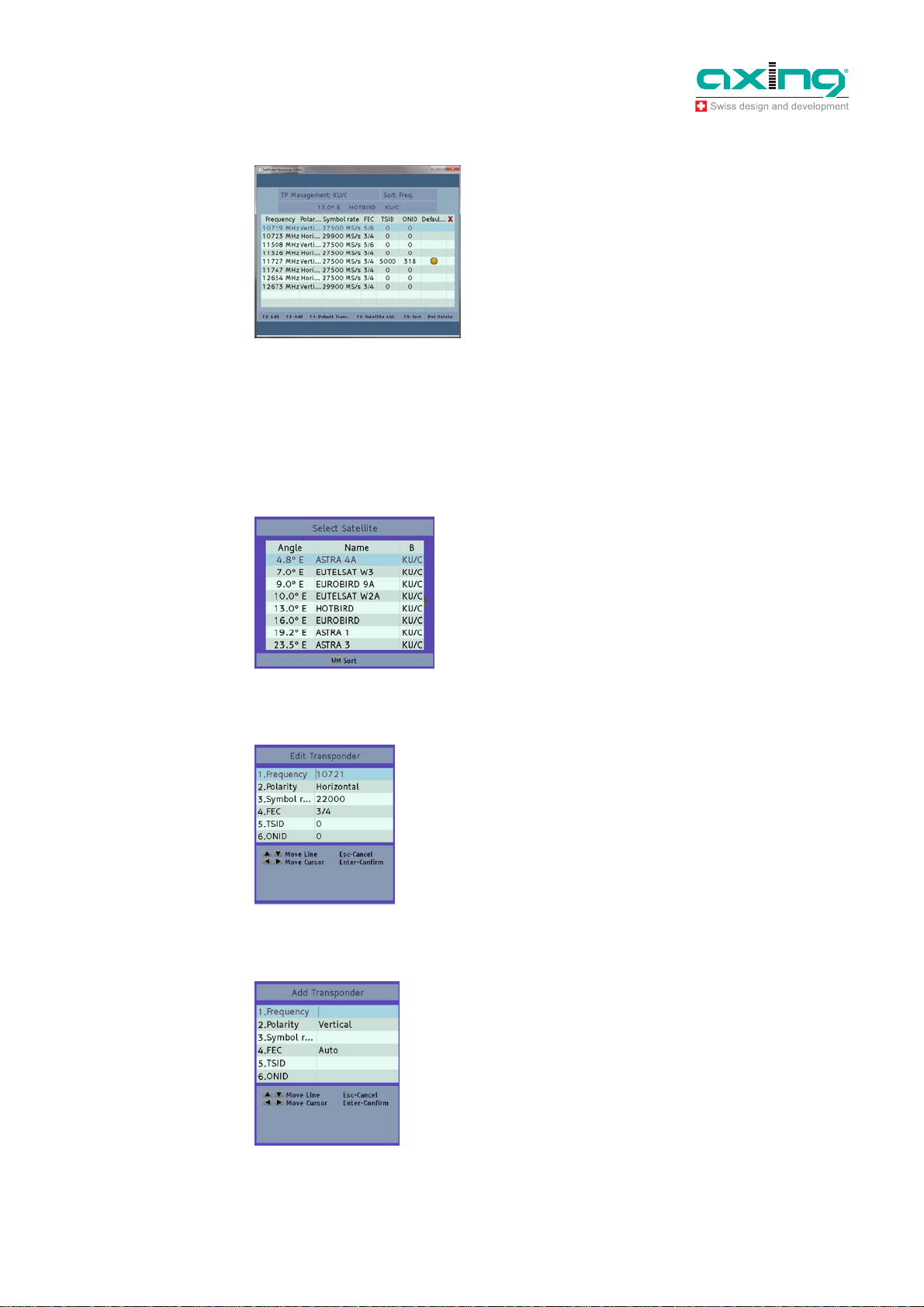
4.4.3 Editing transponders:
Select the menu item Transponder List in the main menu and press Enter key.
The transponder management is opened, and the following menu items are available.
29.08.14 © AXING AG • Reserving change in design and type - We cannot be held liable for printing errors
13
Page 14
Operation Instructions SZU 21-00
Chapter 4: Update
F2-Edit
To change the transponder settings
F3-Add
To add a transponder
F4-Default
To define the default transponder
F5-Satellite List
To switch to the satellite list
F6-Add
To sort the transponder settings
Delete key (Del-Delete)
To delete a transponder setting
Note:
The numbers (frequencies, symbol rate, TSIS, ONID) are edited by means of BACKSPACE, LEFT /
RIGHT arrow keys and 0-9 number keys. You can return to the start menu by pressing the Esc key and
confirm individual functions by pressing the Enter key.
Selecting satellites
Changing the transponder settings
Adding a transponder
Press F5 key
The satellite list is opened.
Select a satellite by means of the arrow keys of the
keyboard.
Press Enter key to confirm the entry
Press F2 key
You can change the frequency, the polarization, the FEC
symbol rate, TSID and ONID.
Press Enter key to confirm the entry
Press Delete key to reject the entry
Press F3 key
You can enter the frequency, the polarization, the FEC
symbol rate, TSID and ONID.
Press Enter key to confirm the entry
Press Delete key to reject the entry
14 © AXING AG • Reserving change in design and type - We cannot be held liable for printing errors 2014-08-29
Page 15
Operation Instructions SZU 21-00
1:
Chapter 5: Technical specifications
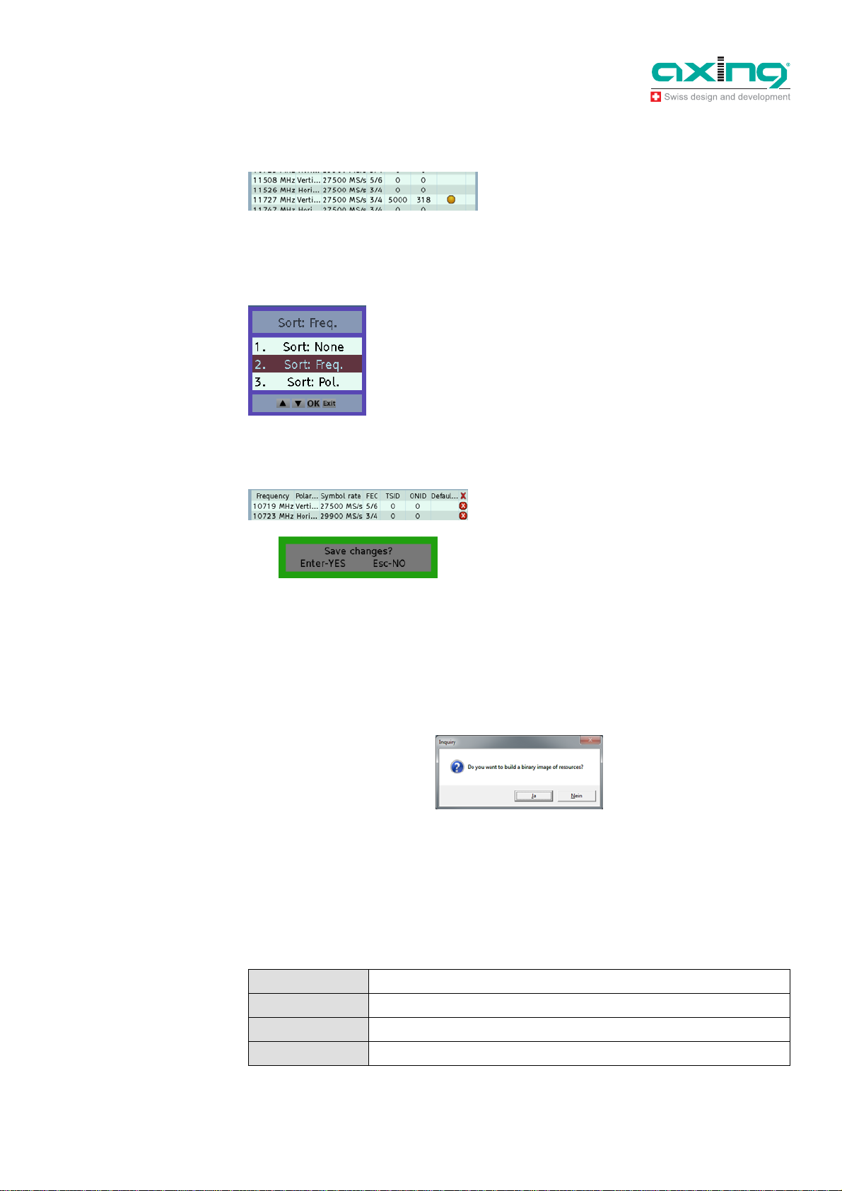
Defining the default transponder
Select a transponder by means of arrow keys and
press F4 key.
A yellow marking will appear in the Default column of
the transponder.
You can define only one transponder as the default
transponder.
Sorting the transponders
Press F6 key
You can sort according to frequency or polarization.
Deleting a transponder
Select a transponder by using arrow keys and press
Delete key.
The transponders are marked for deletion with a red
cross.
Press Enter key to confirm
Press Delete key to cancel the deletion
4.4.4 Closing and saving data
Click in the upper right corner to close the program.
Before the software closes, you will be asked whether you want to save the changes and a so-called
romimageSatfinder.bin file to be created.
Fig. 23:
Saving satellite and
transponder lists to a file
Confirm by pressing Yes. This will save the romimageSatfinder.bin file to the smg folder. This file
contains the new satellite and transponder lists.
Transfer this file to the SAT-Navi (see 4.4 on page 11).
5 Technical specifications
Tab.
Data sheet
Frequency range 950…2150 MHz
RF connecters F female
Operating voltage 13...19 VDC
Current consumption 300mA
29.08.14 © AXING AG • Reserving change in design and type - We cannot be held liable for printing errors
15
Page 16
Operation Instructions SZU 21-00
Chapter 5: Technical specifications
16 © AXING AG • Reserving change in design and type - We cannot be held liable for printing errors 2014-08-29
 Loading...