

Page 1

SKQ 4-01
Operation Instructions
Operation Instructions
8PSK/QPSK - QAM
8PSK/QPSK - QAM
Quattro Module
Quattro
Module
EN
Read and keep
Page 2

Operation Instructions
SKQ 4-01
Safety Notes!
Assembly, installation and service must be carried out by authorized and skilled electricians.
Switch off facility operating voltage or pull out mains plug before starting assembly or service work.
Facility assembly:
In dust-free, dry environment, protected against humidity, vapors, splash water and moisture. In a
location protected against solar radiation. Not within close distance of heat sources. In ambient
temperature of <50°C.
Ensure sufficient ventilation of the device. Do not cover the ventilation slots! - Avoid short circuits!
Damages arising from incorrect connection and/or improper operation are excluded from any liability.
Please observe all relevant standards, regulations and guidelines regarding installation and operation
of antenna facilities.
Ground SAT earth stations using equipotential bonding rails according to EN 50083-1, EN 60728-
11:2010.
Do not carry out any installation and service work during thunderstorms.
2
© AXING AG • Swizzerland • Reserving change in design and type - We cannot be held liable for printing error 14.06.12
Page 3

Operation Instructions
SKQ 4-01
Inhalt
1 Common .............................................................................................................................4
1.1 Scope of delivery...................................................................................................4
1.2 Description ............................................................................................................4
1.2.1
Display elements and connections .................................................... 5
2 Installation and connection .............................................................................................6
2.1 Installation and connection in a headend base unit ..........................................6
2.2 Single operation mode of SKQ 4-01 ....................................................................7
3 Programming .....................................................................................................................8
3.1 First time set-up ....................................................................................................9
3.1.1
Receiver 1+2 or 3+4...........................................................................9
3.1.2
Power-up..............................................................................................9
3.2 Set-up.....................................................................................................................9
3.2.1
Scan Transponder.............................................................................10
3.2.2
Channel List.......................................................................................10
3.3 Other functions....................................................................................................11
3.3.1
Info .....................................................................................................11
3.3.2
Modulator set-up...............................................................................12
3.3.3
Menu Language ................................................................................12
3.4 Exit the configuration..........................................................................................13
4 Technical specification...................................................................................................14
12.09.11 © AXING AG • Swizzerland • Reserving change in design and type - We cannot be held liable for printing error
3
Page 4

Operation Instructions SKQ 4-01
Chapter 1: Common
1
Fig. 1: Front view
Common
1.1 Scope of delivery
1 × 8PSK/QPSK-QAM quattro module SKQ 4-01
1 × DC connection cable SKZ 4-00
1 × operating manual
The remote control and power supply unit are not included in scope of delivery of SKQ 4-01. They are
available optionally or integrated in the basic unit of SKS x-xx.
1.2 Description
SKQ 4-01 is HD compatible remux modulator/transmodulator designed for a processing four 8PSK/QPSK
modulated satellite signals (DVB-S/S2) into four QAM (DVB-C) multiplex. With SKQ 4-01 can be
transmitted scrambled programs without opening them at the head-end.n.
1+2
Die Kassette beinhaltet zwei unabhängig voneinander arbeitende Kanalzüge. Ein Kanalzug besteht aus
einem Haupt-Tuner und einem Neben-Tuner. Insgesamt verfügt die Kassette über vier Tuner:
Main tuner 1
Sub tuner 2
Main tuner 3
Sub tuner 4
3+4
4
© AXING AG • Swizzerland • Reserving change in design and type - We cannot be held liable for printing error 12.09.11
Page 5

Operation Instructions SKQ 4-01
Chapter 1: Common
1.2.1 Display elements and connections
Fig. 2: Display elements and
connections
1. Control switch to program channel 1+2 (left) or channel 3+4 (right). The switch must be set to
middle position when programming is ready
2. Channel number (CCIR)
3. Cable-TV S channel indicator led
4. The signal led shows that the unit is powered
5. IR detector
6. LNB IN
7. USB port is for possible software update
8. Signal led indicates that receiver is locked to selected transport stream
a = sub tuner 1
b = main tuner 1
c = sub tuner 2
d = main tuner 2
9. Bit rate indicator.
Red= overload
Green = under maximum
10. Video (c), Audio L (b), Audio R (a)
11. DC IN (only in stand-alone installation)
12. RF OUT + DC IN in SKS XX-XX system installation
13. Grounding screw
14. Fan
12.09.11 © AXING AG • Swizzerland • Reserving change in design and type - We cannot be held liable for printing error
5
Page 6

Operation Instructions SKQ 4-01
Chapter 2: Installation and connection
2
Fig. 3: Installation and connection
in a headend base unit
Installation and connection
Important
The SKQ 4-01 can either be operated in a head ends basic unit SKS x-xx or in stand alone mode. SAT
ZF signals of the LNB(s) are either provided through optionally available input distributors, a multiswitch
or directly to SAT ZF inputs.
Maximum total current of LNB connector is 250 mA.
2.1 Installation and connection in a headend base unit
If you want to operate the SKQ 4-01 on a head ends basic unit SKS x-xx, plug the twin module into the
output collection field and fasten it by screws. Each free slot may be used. The power supply unit
supplies the module via the output connection field.
Hinweise
6
© AXING AG • Swizzerland • Reserving change in design and type - We cannot be held liable for printing error 12.09.11
For detailed information on the headend base unit, refer to whose operating instructions.
Before inserting or changing a module, pull the mains plug of the head ends basic unit from the
socket! Ground the base plate in order to avoid dangerous overvoltages (attention: risk of fire/death).
Page 7

Operation Instructions SKQ 4-01
Chapter 2: Installation and connection
2.2 Single operation mode of SKQ 4-01
Before installing modules, the power supply must be switched off. Ground the twin module in order to
avoid dangerous overvoltages (attention: risk of fire/death). Use the grounding screw attached to the
device (see 13 in Fig. 2).
Fig. 4: Single operation mode of
SKQ 4-01
In single operation mode of the SKQ 4-01, the power supply is provided by DC injection socket (see 9 in
Fig. 2). A separate power supply unit (SKZ 5-01/-03) is required for it. More units are connected by
means of the DC loop-through. One DC connection cable SKZ 4-00 each is included in the scope of
delivery of SKQ 2-01.
SKZ 5-01 can supply up to 4 modules
SKZ 5-03 can supply up to 2 modules.
In single operation mode of the SKQ 4-01 the outputs of twin modules must be combined together by a
distributor. The input distributors (SKV 2..8-00) in connection with F-double sockets (CFA 3-00) may be
used.
12.09.11 © AXING AG • Swizzerland • Reserving change in design and type - We cannot be held liable for printing error
7
Page 8

Operation Instructions SKQ 4-01
Chapter 3: Programming
3
Fig. 5: Remote control unit
Programming
The receivers and modulators are simple to program with the remote control unit (SKZ 10-00). The main
functions of RCU are shown in Fig. 5 .
Select main menu
Close the menu
Numeric bottuns
Channel information
Confirm selection
Decrease audio level
Increase audio level
Add or remove programs to output
Display BER (Bit error rate)
Select channel list
Scroll through channel list upwards side by side
Scroll through channel list downwards side by side
Channel change upwards
Channel change downwards
Setting output channel
8
© AXING AG • Swizzerland • Reserving change in design and type - We cannot be held liable for printing error 12.09.11
Page 9

Operation Instructions SKQ 4-01
g
Chapter 3: Programming
3.1 First time set-up
When using the unit for the first time, you must first connect video and audio connectors to monitor. After
this you can continue set-up using on-screen menus (see Fig. 3 on page 6).
3.1.1 Receiver 1+2 or 3+4
To control the unit first slide front panel switch to left or right position to control receiver 1+2 or 3+4
respectively.
After exit the programming, the programming selection switch must be set to centre position.
3.1.2 Power-up
Fig. 6: Welcome screen
Fi
. 7: Program info
At power-up this welcome screen is displayed. Main SW and user interface SW version numbers plus
unit serial number are shown.
When the unit is powered the display lights up showing selected output channels (Fig 1. no 2) of main
modulators 1 and 2. The factory set channels are E21 (main modulator 1), E22 (sub modulator 2) and
E23 (main modulator 3), E24 (sub modulator 4).
The display is switched off after 3 minutes. Two signal led indicate, that the unit is powered. The display
lights up again by pressing any button of remote control unit.
Next program info for channel previously selected is displayed and the channel opened, if possible. Info
shows satellite number i.e. DiSEqC switch control, transponder frequency, data rate, FEC and channel
video PID number.
If the channel list is empty, welcome screen will remain displayed.
3.2 Set-up
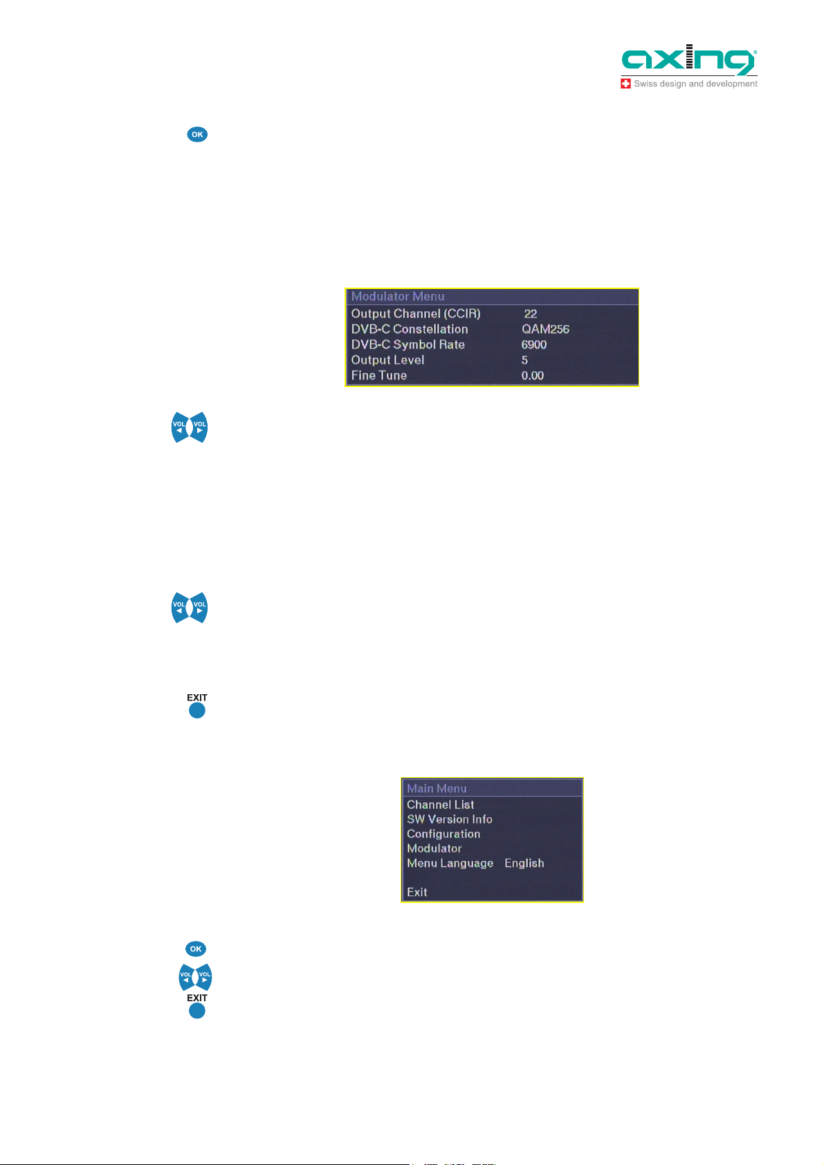
To start set-up, press Menu key . Main menu will be displayed.
Fig. 8: Main menu
Select “Configuration”.
9
12.09.11 © AXING AG • Swizzerland • Reserving change in design and type - We cannot be held liable for printing error
Page 10

Operation Instructions SKQ 4-01
Chapter 3: Programming
3.2.1 Scan Transponder
Fig. 9: Configuration menu
There are two scanning functions. “Scan Transponder” is for main tuner and “Scan Transponder 2” is for
sub tuner.
NOTE!
Fig. 10: Scan Transponder
In sub tuner scan only frequency can be selected. Other parameters are same than in main tuner. Sub
tuner must be scanned always after main tuner. Firstly “Scan Transponder” must be selected. Write the
parameters of transponder and press “Scan”.
If transponder frequencies or other parameter are not known, change to “Select Program Info” In the
“Select Program Info” are listed all stored channels with sequence number, satellite indication (the
satellite is indicated as following A=Astra, B=Hotbird), transponder frequency and band information. You
can scan a transponder also by selecting program name and then press "Scan".
When using non-universal LNBs, you can adjust the local oscillator frequency values accordingly. Output
Id parameters are recommended to keep in “AUTO”. Change them only in special case.
All selectable options in “Scan Transponder” are shown below.
Hinweis !
NOTE!
It takes few minutes to scan transponder.
3.2.2 Channel List
After transponder has been scanned you can select programs from “Channel List” which appears
automatically.
Die Kanalliste wird nur für den Haupttunern angezeigt
On channel list all stored channels are listed with sequence number, satellite indication (the satellite is
indicated as following A=Astra, B=Hotbird), transponder frequency and band information.
Behind channel program name on right column, channel status is shown. “FTA” stands for free channel
available without a Conditional Access module or a viewing card. “CA” stands for Conditional Access
channel.
SKQ 4-01 is only for FTA programs. Scrambled channels can not be opened inside the head-end.
You can scroll the list using up and down arrow keys.
Only the programs from main tuner are selectable for outgoing QAM mux (remux modulator). All
programs from sub tuner are transmitted to outgoing sub mux without change (transmodulator).
After transponder scan, all programs (both FTA and scrambled) are marked with + (default setting).
To select a programs for outgoing QAM stream press SYS key
The meaning of symbols are
10
© AXING AG • Swizzerland • Reserving change in design and type - We cannot be held liable for printing error 12.09.11
Page 11

Operation Instructions SKQ 4-01
g
Chapter 3: Programming
+ = FTA program selected, scrambled program selected but not opened at the head-end,
FTA – or CA – = program is not selected.
To save and exit select + marked program and press OK key.
NOTE!
When FTA time-sharing program (e.g. regional program) is selected to outgoing mux, you must select
also the original program (e.g. national programs) to same mux..
Fig. 11: Channel List
3.3 Other functions
3.3.1 Info
. 12: SW Version Info
Fi
Fig. 13: Selectable options in
configuration menu
NOTE!
In main menu, select “SW Version Info” and press OK to display receiver and user interface version
numbers plus unit serial number info..
Most of the system set-up is done in Configuration Menu. Select “Configuration” and press OK to enter.
Below are all selectable options in Configuration menu.
You can select the audio language in two ways. Firstly you can select from preset languages selecting
“Audio Language” and using left and right arrow keys (Fig 2. no 4 or 5) to select the language name.
Secondly if your language is not among the preset languages you can freely write any 3-character
language name.
Use double arrow keys to select character position, which will be underlined.
and select needed character using up and down keys. Use double arrow keys to exit edit with no
character underlined.
Select “ALL” if all received languages will be transmitted to digital output.
In “LNB Control Mode” you can select Normal or Power OFF using left and right arrow keys.
In “Start-Up Video Display” menu there are options “MPEG2 SD Monitor” and “Modulator Menu”.
When MPEG-4 programs are received or scrambled channels are not descrambled (marked with +) at
the head-end, select “Modulator Menu”. Otherwise select “MPEG2 SD Monitor”.
11
12.09.11 © AXING AG • Swizzerland • Reserving change in design and type - We cannot be held liable for printing error
Page 12
Operation Instructions SKQ 4-01
Chapter 3: Programming
3.3.2 Modulator set-up
To adjust the parameters of outgoing DVB-C stream and other modulator options, select “Modulator” and
press OK.
NOTE!
Fig. 14: Modulator menu
NOTE!
In SKQ 4-01 are four QAM modulators, main modulators 1 (E21 factory default) and 2 (E23) and then sub
modulators 1 (E22) and 2 (E24).
The output frequencies of main modulators are freely selectable. The output frequency of sub modulator
is + 1 channel to main modulator.
All selectable options of modulator menu are shown in below figure.
You can select output channel using left and right arrow keys. The channel number will be displayed
simultaneously on front panel display. The selectable channels are S02 - S10, 5 - 12, S11 - S41 and 21 –
69 (CCIR).
Select DVB-C Constellation. QAM 32, QAM 64, QAM 128 and QAM 256 are selectable. The most
common is QAM 64. If QAM 256 is used, the S/N of network must be very good.
Select appropriate DVB-C Symbol Rate (1000 … 8000). The common symbol rate in most cable
networks is 6900. The used symbol rate effects for the bandwidth. 6900 ksymb/s corresponds to 8 MHz
bandwidth. For channel with only 7MHz bandwith symbolrate must be reduced accordingly to 6111
ksymb/s
To adjust modulator output attenuation use left and right arrow keys. You can fine tune output frequency
when using different channel grid than CCIR. Adjustment is done using left and right arrow keys in steps
of 1 MHz. Adjustment range is 4 MHz. You can monitor the adjusted frequency in parenthesis on the
same line. Select output level. The number indicates gain (0= minimum level and 20 = maximum level).
The optimum bit rate is 80% from maximum.
Press EXIT key to exit from menu. The settings will be saved.
3.3.3 Menu Language
Fig. 15: Menu Language
To select menu language, select “Menu Language” in main menu and press OK..
You can select the menu language using left and right keys.
Press EXIT key to exit menu. The settings will be saved.
12
© AXING AG • Swizzerland • Reserving change in design and type - We cannot be held liable for printing error 12.09.11
Page 13

Operation Instructions SKQ 4-01
Chapter 3: Programming
3.4 Exit the configuration
Select the menu item “Exit” and confirm with OK.
When programming is ready, the front panel switch must be slided to center position. This will prevent
accidental changes to be made, while controlling other units.
Note
The display, except two LED, will be switched off, 6 minutes after programming is finished.
12.09.11 © AXING AG • Swizzerland • Reserving change in design and type - We cannot be held liable for printing error
13
Page 14

Operation Instructions SKQ 4-01
Chapter 4: Technical specification
4
Tab. 1: Data sheet
Technical specification
Number of channels 4
Tuners 4
Input
Input frequency range 950…2150 MHz
Input level 44...84 dBµV/-65…-25 dBm
LNB supply 13/17 V; 22 kHz on/off; DiSEqC 1.0
Waveform 8PSK/QPSK (SCPC, MCPC)
Symbol rate 4…45 Msymb/s
FEC decoder automatic
Transport stream MPEG-2 ISO/IEC 13818 | MPEG-4 ISO/IEC 14496
Input connectors F female
Output
Output frequency range 114…858 MHz
Output channel S2…K69, nachbarkanaltauglich (VSB)
Modulation QAM 32, 64, 128, 256
Symbol rate 1-8 Msymb/s
Output level 82…102 dBµV
MER ≥40 dB
connectors F male
Common
Data interface USB 1
Power consumption 16V=/1,7 A
Dimensions 72 mm × 218 mm × 129 mm
14
© AXING AG • Swizzerland • Reserving change in design and type - We cannot be held liable for printing error 12.09.11
Page 15

Operation Instructions SKQ 4-01
Chapter 4: Technical specification
12.09.11 © AXING AG • Swizzerland • Reserving change in design and type - We cannot be held liable for printing error
15
Page 16

Operation Instructions SKQ 4-01
Chapter 4: Technical specification
16
© AXING AG • Swizzerland • Reserving change in design and type - We cannot be held liable for printing error 12.09.11
 Loading...