

Page 1

MK 8-00 | MK 16-00
MK 8-06 | MK 16-06
Multituner | DVB-C/DVB-T compact headend
Operation instructions
Page 2

Operation instructions | MK 8-00 | MK 16-00 | MK 8-06 | MK 16-06
Table of contents
1. Product description ......................................................................................................................................................... 4
1.1. General .................................................................................................................................................................. 4
1.2. Scope of delivery ................................................................................................................................................... 4
1.3. Inputs/multituner ................................................................................................................................................... 5
1.4. Output/modulators ................................................................................................................................................ 6
1.5. Graphical user interface ......................................................................................................................................... 6
1.6. SMARTPortal ......................................................................................................................................................... 6
1.7. Display elements and connectors .......................................................................................................................... 7
1.7.1. MK 8/16-0x................................................................................................................................................... 7
1.7.2. MK 8-06/16-06 ............................................................................................................................................. 7
2. Mounting and Installation............................................................................................................................................... 8
2.1. Wall mounting ....................................................................................................................................................... 8
2.2. Mounting in a 19“ rack ......................................................................................................................................... 9
2.3. Equipotential bonding ........................................................................................................................................... 9
2.4. Power supply ......................................................................................................................................................... 9
2.5. RF Installation ...................................................................................................................................................... 10
2.5.1. Connection to DVB-T/T2 or DVB-C.............................................................................................................. 10
2.5.2. Connection to DVB-S/S2/S2x ...................................................................................................................... 10
2.5.3. Output ........................................................................................................................................................ 10
2.6. Connection to the Internet................................................................................................................................... 11
3. Configuration ................................................................................................................................................................ 13
3.1. Login and logout ................................................................................................................................................. 14
3.2. Front page ........................................................................................................................................................... 15
3.2.1. Input ........................................................................................................................................................... 15
3.2.2. Outputs ...................................................................................................................................................... 15
3.3. Initialization phase 1 ........................................................................................................................................... 16
3.3.1. DVB-S/S2/S2x ............................................................................................................................................. 16
3.3.2. DVB-C, DVB-T or DVB-T2 ............................................................................................................................ 17
3.3.3. Bit error rate ............................................................................................................................................... 18
3.3.4. Found programmes .................................................................................................................................... 18
3.4. Initialization phase 2 ........................................................................................................................................... 18
3.4.1. Remux mode .............................................................................................................................................. 19
3.4.2. Cross Multiplex Mode ................................................................................................................................ 20
3.4.3. Select all programs ..................................................................................................................................... 22
3.4.4. LCN (Logical Channel Numbering).............................................................................................................. 23
3.4.5. PID Filtering (with MKS 1-01) ..................................................................................................................... 24
3.5. Initialization phase 3 – DVB-C ............................................................................................................................. 25
3.5.1. Configuration of the modulator .................................................................................................................. 25
3.5.2. Fill level ...................................................................................................................................................... 26
3.5.3. Selected Programmes ................................................................................................................................. 26
3.6. Initialization phase 3 – DVB-T ............................................................................................................................. 27
3.6.1. Configuration of the modulator .................................................................................................................. 27
3.6.2. Fill level ...................................................................................................................................................... 28
3.6.3. Selected Programmes ................................................................................................................................. 29
3.7. Maintenance ........................................................................................................................................................ 30
3.7.1. Updating software ...................................................................................................................................... 30
3.7.2. Modulation standard .................................................................................................................................. 31
3.7.3. Changing the IP address ............................................................................................................................. 32
3.7.4. Changing the password .............................................................................................................................. 33
3.7.5. Rebooting ................................................................................................................................................... 34
3.7.6. Erasing service data.................................................................................................................................... 34
3.7.7. Save Initialization Data............................................................................................................................... 34
3.7.8. Upload Initialization Data........................................................................................................................... 35
3.7.9. Device name ............................................................................................................................................... 35
3.7.10. Access to SMARTPortal .............................................................................................................................. 36
3.7.11. Log files ...................................................................................................................................................... 36
3.7.12. Channel list for all devices .......................................................................................................................... 37
3.7.13. Network Information Table (NIT) ................................................................................................................ 37
4. Use of CA modules........................................................................................................................................................ 42
4.1. Insertion of CA modules ...................................................................................................................................... 42
4.2. CI menu for SKM 4x-04M .................................................................................................................................... 42
4.2.1. Using CI menu ............................................................................................................................................ 42
4.3. Decryption of programmes .................................................................................................................................. 43
5. Technical specifications................................................................................................................................................. 44
2 2018-10-05 | Technical improvements, changes in design, printing- and other errors expected.
Page 3

Safety instructions:
∂ The installation of the device and repair work on the device must be carried out only by a professional
in accordance with the applicable VDE directives. In case of incorrect installation, no liability is
assumed.
∂ Never open the device. There are no parts to be maintained by the user inside the device, however,
lethal voltages are present. This also applies to cleaning the device or working on the connections.
∂ Use only the mains cable enclosed to the device. Never replace any parts or make any modifications
to the mains cable. Otherwise, there is a risk of death.
∂ If you intend not to use the device for a longer period of time, we recommend you to completely
disconnect the device from the mains for safety reasons and for saving energy by pulling out the
mains plug.
∂ Let the device adjust to the room temperature before commissioning, in particular if condensation is
present on the device, or if it was exposed to large temperature fluctuations.
∂ The device must be operated only in moderate climate.
∂ The device must be operated only in dry rooms. In damp rooms or outdoors, there is a risk of short-
circuits (attention: risk of fire) or electrical shocks (attention: risk of death).
∂ The device shall not be exposed to dripping or splashing. Do not place objects filled with liquids such
as vases on the device.
∂ Plan the mounting or installation location such that you can easily reach the mains plug and interrupt
the electric circuit in dangerous situations. Select the mounting or installation location such that
children cannot play near the device and its connections without supervision. The mounting or
installation location must allow a safe installation of all connected cables. Power supply cables and
supply cables must not be damaged or squeezed by any objects.
∂ Operate the device only on a flat, firm surface and protect it against unintentional movements.
∂ Never expose the device to direct solar irradiation and avoid direct vicinity of heat sources (e.g.
heaters, other electrical appliances, fireplace, etc.). It must be always ensured that devices with
cooling elements or ventilation slots are not covered or obstructed.
∂ Ensure generous air circulation around the device. This will prevent possible damage to device and
risk of fire due to overheating. It must be always ensured that cables are not located near heat
sources (e.g. heaters, other electrical appliances, fireplace, etc.). The unit must be wall mounted with
at least 5 cm clearance along the 4 sides. For 19-inch rack mounting, there must be at least 5 cm
clearance in front of and behind the unit.
∂ In particular, the warranty and liability shall be excluded for the consequences of incorrect use, in
case of incorrect modifications or repair work carried out by the customer. Use the device only as
described in the operating instructions and in particular according to the state-of-the-art.
∂ The antenna system must be installed and grounded according to the current DIN EN 60728-11
standard.
Herewith AXING AG declares that the marked products comply with the valid guidelines.
You can call up the complete EU declaration of conformity for download by entering the
article in the search field at www.axing.com.
WEEE Nr. DE26869279 | Electrical and electronic components must not be disposed of
as residual waste, it must be disposed of separately.
2018-10-05 | Technical improvements, changes in design, printing- and other errors expected. 3
Page 4

Operation instructions | MK 8-00 | MK 16-00 | MK 8-06 | MK 16-06
1. Product description
1.1. General
MK 8-00 Eight independent multituner inputs
Transmodulates 8 × DVB-S/S2/S2x/T/T2/C into 8 × DVB-C or DVB-T (depending on the
configured modulation standard, see 3.7.2 on page 31)
Expandable to 16 modulators with MKS 8-16 software.
MK 8-06 Like MK 8-00, with 6 CI slots (see chapter 4 on page 42)
MK 16-00 16 independent multituner inputs
Transmodulates 16 × DVB-S/S2/S2x/T/T2/C into 16 × DVB-C or DVB- T (depending on the
configured modulation standard, see 3.7.2 on page 31)
MK 16-06 Like MK 16-00, with 6 CI slots (see chapter 4 on page 42)
Common Features:
∂ Remux | Crossmultiplex
∂ Web-based configuration | Remote maintenance
∂ Suitable for AXING SMARTPortal
∂ Can be used for wall mounting or as a 19" unit
∂ Built-in power supply
1.2. Scope of delivery
1 × Compact headend
1 × AC power cord
1 × Quick start guide
4 2018-10-05 | Technical improvements, changes in design, printing- and other errors expected.
Page 5

1.3. Inputs/multituner
Headend devices with multituner can receive DVB-S/S2/S2x, DVB-T/T2 or DVB-C. For receiving DVB-T/T2 or
DVB-C the LNB power has to be switched off before connecting a antenna cabel to one of the HF
inputs (see 3.3.2 on page 17)!
Direct connection to the LNBs
The devices have a remote supply voltage for the LNB and DiSEqC 1.0 functionalities at the inputs. The inputs
can be connected directly to the LNB.
Multiswitches as input distributors (recommended)
Optionally, you can also use multiswitches as input distributors. The advantage of this solution is that you can
set both the polarization and the satellite via the user interface. Changes in the list of programmes can be
made using remote maintenance, so that it is not necessary to change or modify the input distribution on site.
Demodulation of the data stream
The selection of the frequency and the demodulation of the data stream are both done in the tuner.
If needed, the programmes from the data flow of the demodulated transponder can be filtered (Remux mode).
Thanks to the Cross Multiplex Mode, FTA programmes (Free to Air) can be filtered from the data flow of
several tuners for a common output channel and be bundled again.
The prepared data flow is passed on to the modulators.
2018-10-05 | Technical improvements, changes in design, printing- and other errors expected. 5
Page 6

Operation instructions | MK 8-00 | MK 16-00 | MK 8-06 | MK 16-06
1.4. Output/modulators
The MK 8-0x have eight output modulators. The MK 16-0x have 16 output modulators. All modulators can be
set to any output channel (DVB-C = S2…K87 | DVB-T = S2…K69).
1.5. Graphical user interface
The settings can be changed via the user interface of the integrated web interface. To access the user interface
and thus configure the devices, you need a standard PC/laptop with a network interface and the actual version
of the installed web browser (left).
The configuration interface is "mobile ready" and can therefore also be used from the smartphone or tablet
(right).
1.6. SMARTPortal
AXING ensures with its SMARTPortal, a web-based cloud application, an easy remote access on web
configuration surfaces of its headends.
With AXING’s SMARTPortal a worldwide configuration of all settings or software updates can be ensured. On
customer request AXING can provide the necessary support.
AXING headends ensure a continuous secure and encoded connection to the AXING SMARTPortal. Only
requirement on site is an internet connection (e. g. via LAN, EoC, EoC-WLAN-Bridge, 3G/LTE-Router). There is
no complicated configuration of a router and no additional software for the local computer needed (see 2.6 on
page 11).
6 2018-10-05 | Technical improvements, changes in design, printing- and other errors expected.
Page 7

1.7. Display elements and connectors
1.7.1. MK 8/16-0x
1. LED indicators
Green = modulation is ok
Green (blinking) = something is missing from the programmed TS
Red = modulator overload.
2. Equipotential bonding connection
3. Mains connection
4. HF input LEDs:
Yellow = MPEG data stream present,
Off = MPEG data stream not present
5. RF input 1…4
6. RF input 5…8
7. RF input 9…12 (MK 16-0x only)
8. RF input 13…16 (MK 16-0x only)
9. Test port
10. RF output
11. RJ45 Ethernet connector
1.7.2. MK 8-06/16-06
MK 8-06 and MK 16-06 each have 6 CI slots (CI1 ... CI6).
Which encrypted program you decrypt with which interface, you determine in the configuration.
2018-10-05 | Technical improvements, changes in design, printing- and other errors expected. 7
Page 8

Operation instructions | MK 8-00 | MK 16-00 | MK 8-06 | MK 16-06
2. Mounting and Installation
Installation must be performed by authorized and skilled electricians only.
Before mounting and installation, pull the mains plug (1)!
The antenna system must be installed and grounded according to the EN 60728-11 standard.
The compact headend can be mounted on either at the wall or be mounted in a 19 "rack.
2.1. Wall mounting
The compact headend are factory-fitted with wall brackets.
Note: The unit must be wall mounted with at least 5 cm clearance along the 4 sides.
The installation must be carried out on an even and vertical surface (any unevenness must be
compensated).
Fix the headend with with minimum four pcs. of 4 × 30 mm screws.
The headend must be connected to the equipotential bonding according to EN 60728-11 (3)
8 2018-10-05 | Technical improvements, changes in design, printing- and other errors expected.
Page 9

2.2. Mounting in a 19“ rack
Note: For 19-inch rack mounting, there must be at least 5 cm clearance in front of and behind the unit.
Remove the wall bracket from the housing of the compact headend.
Mount the front plate MKZ 1-00 onto the MK 8 / 16-00 (1).
Slide the compact headend into the 19 "rack.
Screw the compact headend with four screws (2).
Maintain the EN 60728-11.
2.3. Equipotential bonding
To connect the outer conductor of the coaxial cable to the equipotential bonding, use e.g. QEW earthing
angles or CFA earth connection blocks at the inputs and output (see 2.5 on page 10).
2.4. Power supply
The 19 "units have a built-in power supply. For example, connect the units to an electrical outlet (100 ... 240
VAC / 50 ... 60 Hz).
2018-10-05 | Technical improvements, changes in design, printing- and other errors expected. 9
Page 10

Operation instructions | MK 8-00 | MK 16-00 | MK 8-06 | MK 16-06
2.5. RF Installation
2.5.1. Connection to DVB-T/T2 or DVB-C
Before connecting the antenna cabel, the LNB power has to be switched off (see 3.3.2 on page 17).
Active DVB-T antennas have to be supplied by an external power supply.
2.5.2. Connection to DVB-S/S2/S2x
Connection to the LNBs
On the SAT-IF input the compact headends have a remote supply voltage for the LNB and use DiSEqC 1.0
functionalities. Therefore, they can be connected directly to the LNB.
Multiswitches as input distributors
Optionally, you can also use multiswitches as input distributors. The advantage of this solution is that you can
set both the SAT IF level and the satellite via the user interface. Changes in the list of programmmes can be
made using remote maintenance, so that it is not necessary to change or modify the input distribution on site.
2.5.3. Output
If you use more then one compact headend, you have to use a combiner to combine the output signals. Note:
There has to be used galvanic isolator between the output connector and antenna network in Sweden and
Norway state area.
10 2018-10-05 | Technical improvements, changes in design, printing- and other errors expected.
Page 11

2.6. Connection to the Internet
Connection via Ethernet switch to a router which is connected to the Internet.
Connection via Ethernet over Coax to a router which is connected to the Internet.
2018-10-05 | Technical improvements, changes in design, printing- and other errors expected. 11
Page 12

Operation instructions | MK 8-00 | MK 16-00 | MK 8-06 | MK 16-06
Connection via EoC 2-01 in „Bridge Client Mode“ to a WLAN router.
12 2018-10-05 | Technical improvements, changes in design, printing- and other errors expected.
Page 13

3. Configuration
IP address:
192.168.0.145
Subnet mask:
255.255.255.0.
The device is configured via the graphical user interface of the integrated web interface.
To access the user interface, you need a standard PC/laptop with a network interface and the actual version of
the installed web browser. To connect the network interface of the headend to the computer, you need a
commercially available network cable.
The HTTP protocol is used for communication allowing a worldwide remote maintenance of the systems at
various locations via the Internet. Access protection is implemented by means of the password prompt.
The computer and the headend must be in the same subnetwork. The network part of the IP address of the
computer must be set to 192.168.0. and the subnet mask must be set to 255.255.255.0.
The host part of the network address is required for the identification of the devices and can be assigned in the
subnetwork only once. You can allocate to the computer any not allocated host address between 0 and 255.
Hint:
Change the IP address and the subnet mask of your computer accordingly.
(e.g.: IP address:192.168.0.11 and subnet mask: 255.255.255.0)
Control panel > Network connections > LAN connection >Properties > Internet protocol version 4 TCP/IPv4 >
Properties > Use the following IP address:
Click OK to save.
Start your web browser and enter the IP address of the headend: e.g.: 192.168.0.145.
2018-10-05 | Technical improvements, changes in design, printing- and other errors expected. 13
Page 14

Operation instructions | MK 8-00 | MK 16-00 | MK 8-06 | MK 16-06
3.1. Login and logout
The web-based user interface is protected against unauthorized access. When accessing the user interface, the
first thing is the password request.
Enter the default password: Ramsen8262
Click ENTER PASSWORD.
If you are not automatically forwarded to the start
page, click OPEN PAGE.
The standard language of the user interface is English. In the header, the the language of the user interface can
be changed. The possibilities are German (DE) and English (EN). The chosen language applies until the end of
the session.
Language
To log out, click LOG OUT.
Notes:
∂ If the browser is closed while you are still logged in, an automatic logout occurs 2.5 minutes later.
∂ If the browser window stays open, there is no automatic logout. It allows monitoring the installation via
the web browser.
Changing the password:
Please change the password immediately after the first commissioning and choose a sufficiently safe
password. Keep this password at a safe place.
Menu item: MAINTENANCE > SET NEW PASSWORD (see 3.7.4 on page 33).
Changing the IP address:
If needed, the headends can be integrated in a network. For this application, some changes must be applied to
the network configuration.
Menu item MAINTENANCE > SYSTEM.
14 2018-10-05 | Technical improvements, changes in design, printing- and other errors expected.
Page 15

3.2. Front page
The relevant information required for the function of the system are shown on the front page. The decisive
thing is the quality of the signals at the INPUT and the utilization of the modulators at the OUTPUT.
3.2.1. Input
The bit error rate BER of all tuners is shown on the left side. The amount of bit errors for the last 1,000,000
transferred bits is calculated.
Also the LEVEL and the C/N ratio are shown.
3.2.2. Outputs
The fill level of all modulators is shown. 100% modulator fill level correspond to the maximal net data rate of
the output channel.
If the current fill level exceeds the maximal fill level, it may cause image disturbances, e.g. mosaic images.
The data rates of the programmes are not constant. They are dynamically changed by the sender. To ensure an
undisturbed reception, a reserve must absolutely be observed.
We recommend you to set the maximal fill level to 90%.
From a fill level of 95%, this is indicated in red.
2018-10-05 | Technical improvements, changes in design, printing- and other errors expected. 15
Page 16

Operation instructions | MK 8-00 | MK 16-00 | MK 8-06 | MK 16-06
The number of choosen programmes (see 3.4 on page 18) and the configuration of the modulators (see 3.5 on
page 25) have an influence to the fill level.
3.3. Initialization phase 1
Choose INITIALIZATION from the main menu.
During the first phase of the initialization, the tuner settings required for the scan are made and the station
scanning is carried out. The tuners work independently from each other and after the same principle.
3.3.1. DVB-S/S2/S2x
Click TUNER 1…8 to select one tuner.
Configure the needed settings for all tuners.
The SAT IF frequency of the transponder is entered in the input field Freq (MHz).
The input fields Low LNB LO Freq (MHz) and High LNB LO Freq (MHz) correspond to the oscillator
frequencies of the LNB in low and high band. The default settings of the oscillator frequencies are 9,750 MHz
for the low band and 10,600 MHz for the high band.
In the optional field Polarisation, you can switch from horizontal to vertical.
In the optional field DiSEqC, the DiSEqC command signals can be turned off or set to switch a DiSEqC-enabled
multi switch on the positions 1 to 4.
If required, the operating voltage for the LNB can be switched off via the optional field LNB Power.
After all settings have been made, click SCAN.
A rotating circle is shown during the scanning process.
16 2018-10-05 | Technical improvements, changes in design, printing- and other errors expected.
Page 17

3.3.2. DVB-C, DVB-T or DVB-T2
Channel
Input
Channel
Input
Channel
Input
Channel
Input
S 21
306214744163461794
S 22
314224824264262802
S 23
322234904365063810
S 24
330244984465864818
S 25
338255064566665826
S 26
346265144667466834
S 27
354275224768267842
S 28
362285304869068850
S 29
370295384969869858
S 30
3783054650706
S 31
3863155451714
S 32
3943256252722
S 33
4023357053730
S 34
4103457854738
S 35
4183558655746
S 36
4263659456754
S 37
4343760257762
S 38
4423861058770
S 39
4503961859778
S 40
4584062660786
S 41
466
Before connecting an antenna cable to an tuner, the LNB Power has to be set to Off
Click TUNER 1…4 to select one tuner.
In the field LNB power choose the option Off.
Enter 3- digits for
center frequency
Choose “Off”
Enter the center frequency (see table below) for the receiving channel into the field FREQ (MHz).
Note: The center frequeny of channels using a bandwith of 7MHz will be rounded down to 3 full digits. For
example: center frequency of CH 5 = 177,5 MHz, the according input = 177.
Note: All other entry fields are not relevant. Modulation and all other important parameter for reception are
detected automatically.
2018-10-05 | Technical improvements, changes in design, printing- and other errors expected. 17
Page 18

Operation instructions | MK 8-00 | MK 16-00 | MK 8-06 | MK 16-06
3.3.3. Bit error rate
The BIT ERROR RATE is shown. The amount of bit errors for the last 1,000,000 transferred bits is calculated.
3.3.4. Found programmes
After a successful station scanning, the radio and TV stations are shown in the area FOUND PROGRAMS. The
table contains information about the Program Name, the Type and the Encryption.
3.4. Initialization phase 2
In the initialization PHASE 2, the found programmes are subdivided by tuner.
Click on PHASE 2, to select programs.
After the station scanning in initialization phase 1 no programms are activated.
All lines of the programme table have in the "Modulator" column colored buttons M1 to M8/16. The buttons
correspond to the modulators of the headend. The allocation of the buttons is given in the COLOR CODES
legend.
You can assign programmes to modulators in REMUX MODE or in CROSS MULTIPLEX MODE.
With each programme you asign to an modulator, the data rate rises.
The performed modifications are only taken over by the system when you click on SAVE CHANGES.
18 2018-10-05 | Technical improvements, changes in design, printing- and other errors expected.
Page 19

3.4.1. Remux mode
If the the Network ID are set on auto, the device works in the Remux mode. In this mode, the IDs from the set
transponder and from the satellite are used and forwarded to the modulators with virtually no changes. The
TS ID1 to TS ID8/16 of the modulators, are also set on auto.
Note:
If the device is already set to CROSS MULTIPLEX MODE, set the Network ID to auto.
Click on SAVE CHANGES.
The device ist set back to REMUX MODE.
2018-10-05 | Technical improvements, changes in design, printing- and other errors expected. 19
Page 20

Operation instructions | MK 8-00 | MK 16-00 | MK 8-06 | MK 16-06
Assigning programmes
Every tuner is assigned to a modulator. The programmes of the tuner can only be assigned to the associated
modulator.
For example click in table TUNER 1 on M1.
The program is assigned to modulator 1. The button of the modulator is highlighted in color (a new click on
a modulator allow the assignment to be canceled. The modulator fades then again).
Choosen
programs for
modulator 1
Choose the programmes for TUNER 1 to TUNER 8/16.
Click on SAVE CHANGES.
The assignment is saved tot he device.
3.4.2. Cross Multiplex Mode
The cross multiplex mode is used:
∂ To split the programmes of a transonder to several modulators.
∂ To merge pogams of several transponders into one output channel.
Transmission capacities in the distribution networks can be optimized.
Change the Network ID to a value greater than zero.
20 2018-10-05 | Technical improvements, changes in design, printing- and other errors expected.
Page 21

Click on SAVE CHANGES.
The IDs of the transport streams TS ID1 to TS ID8[16] are automatically incremented by one to eight[16], the
cross multiplex mode is activated.
Important:
∂ A splitted transponder works like two transponders.
∂ If you use the cross multiplex mode in several headends, the Network IDs of the headends have to be
different.
2018-10-05 | Technical improvements, changes in design, printing- and other errors expected. 21
Page 22

Operation instructions | MK 8-00 | MK 16-00 | MK 8-06 | MK 16-06
Assigning programmes to the modulators
In the cross multiplex mode, the tuners are no longer assigned to one modulator.
Programs,
which are
assigned to
modulator 2
Click the table TUNER 1 to TUNER 4 on M1.
The programs are assigned to modulator 1.
Spliting the programmes of a transonder
If there are to much programms transmitted in one transponder, they can be splitted to several modulators.
The programms of
one transponder
are spitted to two
modulators
For example: choose modulator M1 for two programmes and modulator M2 for two other programmes.
3.4.3. Select all programs
Activate the option Select all incoming programs, with each program of the tuner the modulator button
is activated.
Note: If the option is activated, then no settings can be made in the columns LCN, decrypt etc.
22 2018-10-05 | Technical improvements, changes in design, printing- and other errors expected.
Page 23

3.4.4. LCN (Logical Channel Numbering)
During the scan of TV stations, the stations are usually saved in the sequence of the channel lists in tuner 1-4.
The LCN function enables channel allocation for the station scan of the TV devices. The TV device must support
the LCN function.
∂ LCN can be used in REMUX as well as in Cross-Multiplex-Mode.
∂ Different LCN standards can be selected with the drop down menue Region. This standard may vary from
area to area.
∂ An LCN can only be entered for programs assigned to a modulator.
Click on the LCN column for the corresponding program.
Enter the LCN with the keyboard or increase / decrease the LCN with the arrow buttons right of the number.
Enter a separate LCN for each desired program.
To clear the LCN, enter 0 in the LCN column.
Click SAVE CHANGES.
The numbers of the channels are saved.
2018-10-05 | Technical improvements, changes in design, printing- and other errors expected. 23
Page 24

Operation instructions | MK 8-00 | MK 16-00 | MK 8-06 | MK 16-06
3.4.5. PID Filtering (with MKS 1-01)
With the fee-based software extension MKS 1-01, individual packages can be filtered out of the transport
stream. The MKS 1-01 must be installed by the AXING support (this requires an internet connection for the
headend).
Click on one of the programs.
The table with the Packeges opens. This contains the name, the PID and a check mark. By default, all PIDs
are initially selected.
Remove the check mark if desired.
The packet is no longer transmitted in the transport stream.
Edit service ID (in crosmultiplex mode only)
In crosplex mode you can also edit the service ID.
Not provided modifications will cause problems!
Changes of the SID are only necessary for STBs using fix preset IDs. These STBs are used of some providers to
suppress reception for external devices. Modifications should only be done after consulting the provider.
Enter the Service ID with the keyboard or increase / decrease the ID with the arrow buttons right of the
number.
Click on the green check mark to accept the ID or on the red cross to discard the entry.
24 2018-10-05 | Technical improvements, changes in design, printing- and other errors expected.
Page 25

3.5. Initialization phase 3 – DVB-C
Note: Depending on the modulation standard the signals are modulated into DVB-C or DVB-T (see 3.7.2 on
page 31).
In phase 3, the modulators are configured.
Click on PHASE 3, to modify the setting of the modulator.
The output channels are compulsory assigned to adjacent channels.
3.5.1. Configuration of the modulator
Output channels and
channel spacing
DVB-C modulation: With DVB-C modulation, you can choose between 32QAM, 64QAM, 128QAM and
DVB-C symbol rate: The DVB-C symbol rate can be freely set between 1000 and 7500. The standard
Common Output level The Common Output Level option include a general attenuation of all modulator
Fine Level The Fine Level option include fine attenuation from 0 to -3dB of each modulator
Fine Tune: The Fine Tune adjustment of the output channel is performed in 0.5 MHz steps.
2018-10-05 | Technical improvements, changes in design, printing- and other errors expected. 25
The modulators can be set to any output channel between S2 and CH 87. No
output channel can be assigned several times!
256QAM. 256QAM enables the highest data transmission rate, but it also requires
the best network quality.
value is 6900. Some networks also work with 6875. When working with a
bandwidth of 7 MHz, 6111 is customary.
outputs. The highest output level is reached with a setting of 20 dB, the lowest
level with a setting of 0 dB.
output and the deactivation of the modulator (off).
Page 26
Operation instructions | MK 8-00 | MK 16-00 | MK 8-06 | MK 16-06
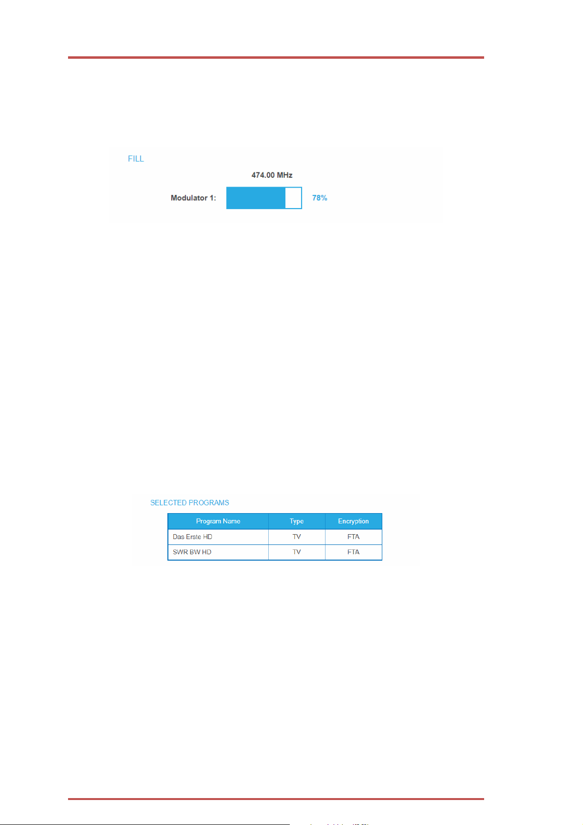
3.5.2. Fill level
The fill level depends on the number of activated channels in the channel list (menu item Phase 2) If the CROSS
MULTIPLEX MODE is active, it must be ensured that the maximum number of activated channels in one
modulator is not exceeded.
The data rate of the channels on the DVB-S/S2/S2x transponders may vary depending on the image contents
and on the transmission quality. To ensure an undisturbed reception, a reserve must absolutely be observed.
We recommend you to set the maximum fill level to 95%. If the current fill level exceeds the maximal fill level,
it may cause image disturbances, such as mosaic images. The LEDs on the front panel will light up in red in this
case.
The data rate of a DVB-C channel depends on the selected channel bandwidth (7 or 8 MHz), the set symbol
rate and the DVB-C modulation (QAM32;64;128;256) of the modulator.
If the displayed data rate exceeds 95%, there are different possibilities
to change it:
Change to a channel with a bandwidth of 8 MHz if a 7 MHz channel was selected previously.
Set DVB-C modulation to a larger value, for example, change from QAM 64 to QAM 128.
Reduce the number of selected channels in the channel list.
If the connected receivers support this option, increase the symbol rate.
3.5.3. Selected Programmes
The programme table SELECTED PROGRAMS shows the programmes that were activated in phase 2.
26 2018-10-05 | Technical improvements, changes in design, printing- and other errors expected.
Page 27
3.6. Initialization phase 3 – DVB-T
Note: Depending on the modulation standard the signals are modulated into DVB-C or DVB-T (see 3.7.2 on
page 31).
In phase 3, the modulators are configured.
After assigning programmes to the modulator the fill level has to be conntrolled. With the parameters of the
modulator, the datarate can in certain circumstances be reduced.
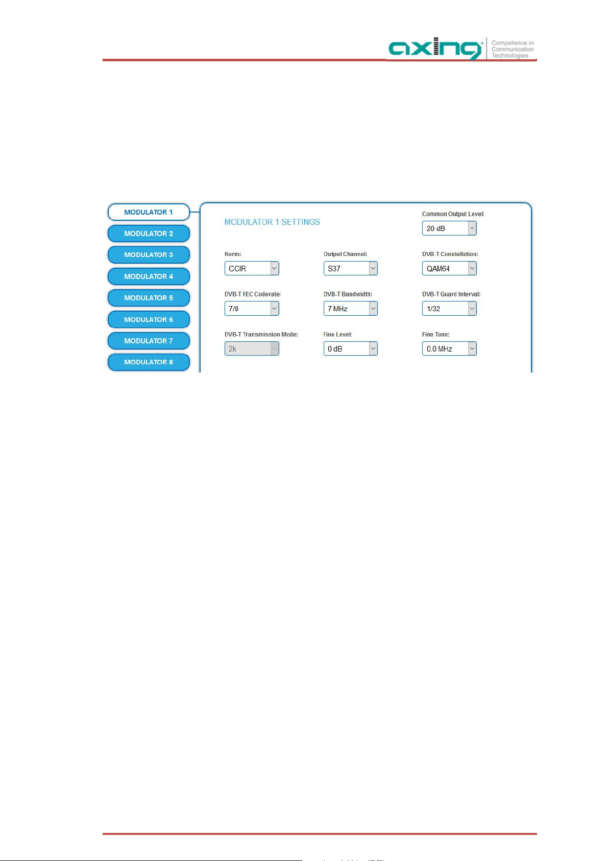
3.6.1. Configuration of the modulator
Norm: In this selection field, you can set the norm for the output channel spacing.
Note: Changing the norm works now according to following rules:
CCIR-->Australia : all modulators forced to 7MHz
Australia-->CCIR : all modulators forced to 8MHz, however with following
exception: low channels S2-S20 are 7MHz only, so those remain in 7MHz
Output channel: The first modulator can be set to any output channel between S2 and CH 69.
The other three modulators are automatically set by incrementing the output
channels in accordance with the chosen channel spacing.
For example: modulator 1 = Channel 21
modulators 2, 3 and 4 = Channels 22, 23 and 24
Common Output level The Common Output Level option include a general attenuation of all
modulator outputs. The highest output level is reached with a setting of 20 dB,
the lowest level with a setting of 0 dB.
DVB-T modulation: The modulation can be set on QPSK, on QAM 16 or on QAM 64.
The QPSK-setting provides the smallest data rate to the output channel. The
QPSK-modulation process is used in bad distribution networks because of its
robustness against disturbances and of its safe transmission.
The QAM-modulation process allow reaching higher data rates, so that more
programmes can be transmitted on a channel. The QAM 64-modulation gives
the highest data rate.
∂ QPSK (2 bit) – small data rate – very robust signal.
∂ QAM 16 (4 bit) - middle data rate.
∂ QAM 64 (6 bit) - high data rate.
2018-10-05 | Technical improvements, changes in design, printing- and other errors expected. 27
Page 28

Operation instructions | MK 8-00 | MK 16-00 | MK 8-06 | MK 16-06
DVB-T FEC (forward error
correction):
Thanks to the error correction, errors resulting from high-disturbed
transmission routes can be balanced by restoring data.
The data required to restore the signal are included in the transmitted FEC bits.
Changing the FEC factor modifies the part of the FEC data in relation to the
application data.
A higher part of FEC data means an higher transmission redundancy. But this
reduces the bandwidth for the useful data too.
A FEC of 7/8 means the highest rate for the useful data and the smallest
transmission redundancy.
∂ FEC 1/2 - small data rate - strong protection against errors.
∂ FEC 7/8 - high data rate - weak protection against errors.
DVB-T bandwidth: The DVB-T standard plans a broadcast on 6, 7 or 8 MHz channels. A bigger
bandwidth means that more data can be transmitted on a single channel.
In the CCIR channel spacing, the lower channels: C5…S20 have a provided
bandwidth of 7 MHz. The other channels have a bandwidth of 8 MHz.
If the bandwidth is changed, the channel does not correspond any longer to
the set channel spacing. Therefore, the output frequency for all 4 modulators
also changes.
DVB-T guard interval: A guard interval is transmitted between the symbols of the useful signal.
This guard interval avoids the intersymbol interference during the DVB-T
transmission.
The delayed signals of other synchronized DVB-T senders or reflections have no
effects on the decoding of the useful signal if they arrive during the guard
interval. The period of the echoes must be shorter than the duration of the
guard interval.
Changing the guard interval adjusts the ratio between the transmission
duration of the useful symbols and the duration of the guard interval.
A great guard interval (e.g. 1/4) leads to a really small data rate.
When transmitting on a perfect coaxial distribution network, a really small
guard interval (1/32) is enough.
DVB-T transmission
modes (2 k and 8 k):
Using the 8 k mode is recommended for reflections with really long durations.
Due to the long symbol duration, long guard intervals are possible.
Fine Level: The Fine Level option include fine attenuation from 0 to -3dB of each
modulator output and the deactivation of the modulator (off).
Fine Tune: The fine Tuning of the output channel is performed in 1 MHz steps.
3.6.2. Fill level
The data rate of the sender may vary depending on the image contents and on the transmission quality. To
ensure an undisturbed reception, a reserve must absolutely be observed.
28 2018-10-05 | Technical improvements, changes in design, printing- and other errors expected.
Page 29

We recommend you to set the maximal fill level to 90%.
If the current fill level exceeds the maximal fill level, it may cause image disturbances, e.g. mosaic images.
If the net data rate of the signal exceeds the net data rate of the output channel, the modulator overflows. This
overflow leads to disturbances. If the modulator overflows, the status LED on the front side of the device lights
in red.
Filtering the programmes reduces the net data rate of the input signal. Subsequently, the net data rate of the
output signal is also reduced.
The data rate of the DVB-T channel depends furthermore on the chosen channel bandwidth (7 or 8 MHz), on
the set error correction rate (FEC) and the modulation rate (QPSK, QAM16, QAM64) of the modulator.
If the displayed data rate exceeds 90%, there are different possibilities to change it:
Change to a channel with a bandwidth of 8 MHz if a 7 MHz channel was selected previously.
Raise the modulation rate to 64 QAM. QPSK corresponds to the lowest, the QAM64 setting to the highest
output data rate.
Set the forward error correction to 7/8. With this setting, the data rate is increased, but the error
correction is lower. A lower error correction requires a better transmission quality from the antenna
network.
Set the guard interval to 1/32. This shorter guard interval allows you to reach greater data rates.
Reduce the number of selected programmes in the channel list.
COFDM modulated channels allow net data rates from 4.98 up to 31.67 Mbit/s (typically 24).
Modulation Code rate Guard interval
1/4 1/8 1/16 1/32
QPSK 1/2 4.976 5.529 5.855 6.032
2/3 6.635 7.373 7.806 8.043
3/4 7.465 8.294 8.782 9.048
5/6 8.294 9.216 9.758 10.053
7/8 8.709 9.676 10.246 10.556
16-QAM 1/2 9.953 11.059 11.709 12.064
2/3 13.271 14.745 15.612 16.086
3/4 14.929 16.588 17.564 18.096
5/6 16.588 18.431 19.516 20.107
7/8 17.418 19.353 20.491 21.112
64-QAM 1/2 14.929 16.588 17.564 18.096
2/3 19.906 22.118 23.419 24.128
3/4 22.394 24.882 26.346 27.144
5/6 24.882 27.647 29.273 30.16
7/8 26.126 29.029 30.737 31.668
3.6.3. Selected Programmes
The programme table SELECTED PROGRAMS shows the programmes that were activated in phase 2.
2018-10-05 | Technical improvements, changes in design, printing- and other errors expected. 29
Page 30

Operation instructions | MK 8-00 | MK 16-00 | MK 8-06 | MK 16-06
3.7. Maintenance
The menu entry MAINTENANCE enables software updates, changing the IP address, changing the password,
restarting the headend and erasing service data.
Under Current Settings, you will find the following information:
∂ Firmware version: Displays the firmware version and the output modulation type.
∂ Software version: Displays the version of the interface
∂ Serial number of the device
∂ Processor temperature - must remain below 90° C
∂ Ventilation temperature - must remain below 50° C (only from hardware version 12-2018)
∂ RF output level OK (only from hardware version 12-2018)
Important: If you stay on the maintenance page for more than 2.5 minutes, an automatic logout will occur
and you will have to repeat the login procedure.
3.7.1. Updating software
After an update, initialization data saved with older Software versions can be loaded into the headend with
a newer Software version.
Initialization data saved with the current Software versions can not be loaded into headends with an
older Software version.
Therefore, if possible, make a Software update of all headends.
We recommend the AXING SMARTPortal for easier handling and overview (see 1.6 on page 6)
Download
Software updates are available at https://axing.com/en/downloads/software-and-firmware/
> Software for compact headends
Download the current version of the file to your computer and unpack it.
30 2018-10-05 | Technical improvements, changes in design, printing- and other errors expected.
Page 31

Update
New software for the graphical user interface can be installed under SOFTWARE FILE.
Click under SOFTWARE FILE on „Browse…“.
Browse for the file on your computer.
Click on UPDATE.
The file will be uploaded to the device.
After this the update of the device begins, the remaining time ist shown as a countdown.
The headend will be automatically rebooted after an update. The enter password dialog will be displayed.
After the Update, log in again.
3.7.2. Modulation standard
Depending on the modulation standard the output signals are modulated into DVB-C or DVB-T.
2018-10-05 | Technical improvements, changes in design, printing- and other errors expected. 31
Page 32

Operation instructions | MK 8-00 | MK 16-00 | MK 8-06 | MK 16-06
Select a Modulation Standard.
Click SAVE & REBOOT.
The changing of the modulation standard begins, the remaining time ist shown as a countdown.
The headend will be automatically rebooted, the enter password dialog will be displayed.
Enter the password again.
Check especially the modulator settings and their fill level.
3.7.3. Changing the IP address
The network options are configured under the menu item MAINTENANCE> SYSTEM OPTIONS.
Dynamic IP adress
Use dynamic IP address to connect the device to a network with a DHCP server.
Static IP adress
Use a static IP address to connect the device to a network with a fixed IP address. The IP address,
netmask and the gateway can be changed here. In addition, DNS server 1 and DNS server 2 can be
entered.
32 2018-10-05 | Technical improvements, changes in design, printing- and other errors expected.
Page 33

Click SAVE & REBOOT to confirm and save the changes.
When the changes are saved, the device will reboot automatically.
The new IP address has to be entered in the web browser and the enter password dialog will be
displayed.
3.7.4. Changing the password
The default password is: Ramsen8262.
The default password should be changed right after commissioning the headend.
Type an new password with 8-10 characters (letters and/or digits).
Re-enter the password.
2018-10-05 | Technical improvements, changes in design, printing- and other errors expected. 33
Page 34

Operation instructions | MK 8-00 | MK 16-00 | MK 8-06 | MK 16-06
Click SAVE CHANGES to confirm and save the changes.
When the changes are saved, the frontpage will be shown.
3.7.5. Rebooting
Under REBOOT THE SYSTEM the device can be rebooted.
Click on REBOOT.
After rebooting, the password must be entered again.
Note: If SAT signals are temporarily unavailable (e.g. due to snow), the headend will reboot every 10 minutes.
This ensures that all configured programmes will be available once the signal becomes available again.
3.7.6. Erasing service data
In the section ERASE SERVICE DATA you can erase the settings from phase 2. The transponder data must be
read again for tuners 1-4 by executing a scan.
The headend is also set to remux mode.
Click on erase.
The frontpage will be shown.
3.7.7. Save Initialization Data
In the section SAVE SYSTEM INITILIZATION DATA TO FILE you can save the current initilization data from phase
1 to 3 into a file on your computer.
Click on SAVE.
The data will be saved in a file called config.dat at the download folder on your computer.
Click on PDF TO PRINT.
A PDF will be generated and saved in a file called config.pdf at the download folder on your computer.
Note: Password and IP adress will not be saved.
34 2018-10-05 | Technical improvements, changes in design, printing- and other errors expected.
Page 35

3.7.8. Upload Initialization Data
In the section UPLOAD SYSTEM INITILIZATION DATA FROM FILE you can upload the initiaization data from a
file to the modul.
Choose a configuration file.
Click on UPLOAD.
The upload will take a few seconds.
After the upload you have to log in again.
3.7.9. Device name
In the section DEVICE NAME you can set a new device name for the headend.
Enter a name in the field SET NEW DEVICE NAME.
Click on SAVE CHANGES.
The new device name is shown at the login.
2018-10-05 | Technical improvements, changes in design, printing- and other errors expected. 35
Page 36

Operation instructions | MK 8-00 | MK 16-00 | MK 8-06 | MK 16-06
3.7.10. Access to SMARTPortal
If you are a registered user of the SMARTPortal, then you can remotely control the headend via the
SMARTPortal and, if necessary, receive support from AXING.
Prerequisite is an internet connection for the headend.
In the State field, select Enabled.
Activate, if required, the option AXING support allowed.
In the field Location, enter a name for the location of the headend. This name will appear later in the
SMARTPortal to help you identify the headend.
In the field Email address, enter the e-mail address with which you are registered at SMARTPortal.
In the field User key, enter the user key that you received when registering at SMARTPortal.
Click on SAVE & REBOOT. The data is saved, the headend is rebooted and the connection to the
SMARTPortal is established.
Where required, you have to adjust the connection data (see 3.7.3 on page 32).
3.7.11. Log files
In the section LOGS you can view the Log files .
Choose Status Log.
The status log is written to RAM and starts again after a restart. In the status log for example, the lock in
time and the frequencies of the tuners are stored.
Select System log.
The system log is written to the flash memory, so it is still available after a restart. In the system log for
example, the boot time and hardware defects are stored.
36 2018-10-05 | Technical improvements, changes in design, printing- and other errors expected.
Page 37

3.7.12. Channel list for all devices
You can create a common channel list for all devices with the same output modulation in the network.
Select the headends that shouled be included in the channel list.
Note: You can only select headends with the same output modulation.
Click on PRINT To PDF.
A PDF of the list is generated which you can open or save.
3.7.13. Network Information Table (NIT)
The NIT contains information about the signal configuration of a headend. A TV needs this information for a
fast channel search. The LCN (Logical Channel Numbering) is located within the NIT, which virtually allocates
the programs to a place.
The headend provides an auto NIT at the factory, which includes all channels from 114 MHz to 1002 MHz and
only the most important parameters such as symbol rate and modulation.
Operation with auto NIT supplies all channels from
114 MHz to 1002 MHz.
Operation leads to a conflict because of two NITs
with ON IDs and Network IDs.
2018-10-05 | Technical improvements, changes in design, printing- and other errors expected. 37
Page 38

Operation instructions | MK 8-00 | MK 16-00 | MK 8-06 | MK 16-06
Operation does not lead to conflict (NIT, ON ID,
Network ID). But no LCN from the headend without
Ideal Solution: One common NIT, ON ID, Network ID
and LCN from both headends.
MKS 1-00 is delivered.
Start NIT Configuration
Click on NIT CONFIGURATION to open the settings dialog.
Select type
Select Auto.
An NIT is created that contains all channels (from 114 MHz to 1002 MHz).
The unoccupied channels contain only the most important parameters such as symbol rate and
modulation.
Select Off.
There is no NIT created and therefore no LCN output.
Select Manual.
The input fields for reading, checking and uploading the NIT are displayed.
Note: Only with the software extension MKS 1-00 can the type be set to Manual and a Network
Information Table (NIT) be read from the devices, edited and uploaded back to the devices. The MKS 1-00
must be installed by AXING support (for this purpose, a connection with the Internet is necessary).
38 2018-10-05 | Technical improvements, changes in design, printing- and other errors expected.
Page 39

Read NIT
Under STEP 1: READ NIT (DVB-C) the devices in the network are displayed.
Select the devices from which the NIT is to be read out.
The device you are currently configuring (This device) is always selected.
Click on READ NIT.
The data of the devices are read in and listed under STEP 2: VERIFY NIT.
Note: If necessary, you must reset the NIT before importing (see „Reset the NIT“ on page 40).
NIT Check
Note: If the NIT is edited, the headend automatically switches to cross-multiplex mode.
Values that overlap
Values that overlap are displayed in red. These errors must be cleaned up before uploading.
Notes:
∂ Different TS-IDs must always be assigned
∂ The ON-ID must be the same for all headends
2018-10-05 | Technical improvements, changes in design, printing- and other errors expected. 39
Page 40

Operation instructions | MK 8-00 | MK 16-00 | MK 8-06 | MK 16-06
Edit NIT
Click the pen symbol next to a line.
The fields can be edited.
Click on the plus sign in the column header.
An additional line is inserted.
Enter plausible data in the fields, matching the other values.
Click on the plus sign next to the cell.
The line will be adopted.
Add cell
Adopt cell
Edit cell
Click the wastebasket icon next to a line.
The line is deleted.
Upload NIT to the devices
Select the devices you want to upload to.
Click UPDATE.
The data is uploaded and stored in the headend.
Delete cell
Reset the NIT
Resetting the NIT is necessary in certain circumstances.
Example:
Three devices are used.
40 2018-10-05 | Technical improvements, changes in design, printing- and other errors expected.
Page 41

In the first device, the NIT is edited and uploaded to all devices. Subsequently, in the modulator output of the
first device, parameters such as the channel output frequency are changed. If the NIT is read in again, the old
channel output frequency will also be read in as it is still in device 2 and 3. Resetting removes all previous
loaded NIT configurations from the devices. These now only return their current configured settings while
reading.
Click RESET NIT.
The NIT entries of the devices are reset.
2018-10-05 | Technical improvements, changes in design, printing- and other errors expected. 41
Page 42

Operation instructions | MK 8-00 | MK 16-00 | MK 8-06 | MK 16-06
4. Use of CA modules
4.1. Insertion of CA modules
Up to six CA modules can be inserted into the CI-slots at the front side of the MK 8-06 or MK 16-06.
Carefully insert the CA modules to the corresponding CI slot without exerting force.
4.2. CI menu for SKM 4x-04M
In the CI menus, settings of CA modules can be made. The buttons for opening the CI menu will be activated
after the modules have been plugged in and initialised.
Active buttons for
the CI menu.
Click one of the buttons.
The corresponding CI menu is displayed.
4.2.1. Using CI menu
The content of the CI menu depends on the CAM manufacturer and the card being used. Depending on the
manufacturer, various settings are possible. Information on validity and authorisation are the most important.
Please observe the operating instructions provided by the manufacturer.
The Content depends on used
CAM
Input and navigation field
According to the used CAM different settings can be done. Most important is getting information about
authorisation.
The input and navigation field is used for navigation within the CI menu.
42 2018-10-05 | Technical improvements, changes in design, printing- and other errors expected.
Page 43

Use Up or Down to reach a higher or lower selection point.
Use Ok to enter a corresponding sub menu or confirm a selection.
Use Menu to come back to the next superordinate level.
Use Exit to leave the menu.
4.3. Decryption of programmes
Scrambled programmes are indicated by the abbreviation CA in the column Encryption of the TUNER table.
By default, in the column Decrypt the option no is choosen. The program will be transferred to the modulator
in encrypted form and must be decrypted in the receiver.
If CA modules are plugged in, the corresponding programmes can be decrypted.
Choose a CI slot
Choose CI 1…CI 6 in the column Decrypt.
The programm will be transferred to the choosen modulator in decrypted form.
2018-10-05 | Technical improvements, changes in design, printing- and other errors expected. 43
Page 44

Operation instructions | MK 8-00 | MK 16-00 | MK 8-06 | MK 16-06
MK 8
-00/MK 8
-06MK 16
-00/MK 16
-
06
Input tuner
8 × DVB
-
S/S2/S2x/T/T2/C
16 × DVB
-
S/S2/S2x/T/T2/C
DVB-C | DVB
-
T/T2 | DVB
-
S/S2/S2X
DVB-C | DVB
-
T/T2 | DVB
-
S/S2/S2X
LNB voltage
13/17 V; 22 kHz on/off; DiSEqC 1.0
LNB current per input (max.)
150 mA
Symbol rate
1,5…45 MS/s
Input error correction
automatic
Input connecto
r, female
8 × F
16 × F
Output TV channels
8 × DVB
-
C/DVB
-T16 × DVB
-
C/DVB
-
T
DVB-C | DVB
-
T
Output channels DVB
-
C | DVB
-TS2…K87 | S2…K69
Output level adjustable
80…100 dBµV
Output modulation DVB
-
C | DVB
-TQAM 32, 64, 128, 256 | QPSK, QAM 16, 64
Output transmission symbol rate
1-7,5 M'Symbol sec
40 dB |
36 dB
FFT mode DVB
-T2k, 8k
FEC DVB
-T1/2, 2/3, 3/4, 5/6, 7/8
Output guard interval DVB
-T1/4, 1/8, 1/16, 1/32
Output connec
tor, female
1 × F
Test port output
-
30 dB
Data interface
2 × RJ45
Operation voltage
100…240 VAC/50…60 Hz
Power consumption
50 W
60 W
(acc. to EN 60065)
Dimensions (W × H × D) appr.
480 × 253 × 47 mm
5. Technical specifications
Input frequency range
Input level
Output frequency range
MER DVB-C | DVB-T
50…898 MHz | 900…2150 MHz
49…84 dBµV | 39…84 dBµV | 43...84 dBµV
111…1006 MHz | 111…862 MHz
″
″
Ambient temperature range
-10°C…+50°C
44 2018-10-05 | Technical improvements, changes in design, printing- and other errors expected.
Page 45

2018-10-05 | Technical improvements, changes in design, printing- and other errors expected. 45
 Loading...