

Page 1

Technische Daten:
Frequenzbereich 175…862 MHz
Kanäle 5…12, S11…S41, 21…69
Welligkeit ± 1,0 dB
Ausgangspegel 70 dBµV
HF Ausgangsimpedanz 75 Ohm
Video Eingangsimpedanz 75 Ohm
Audio Eingangsimpedanz 10 kOhm
Video Eingangspegel 1 V
Audio Eingangspegel 1 V
Anschlüsse HF (Ausgang) F-Buchse
AVM 1-02
Anschluss Video Cinch-Buchse
Anschluss Audio (mono) Cinch-Buchsen
Stromaufnahme 200 mA
Netzteil 230 V~/50 Hz 6 V=/500 mA
Maße ca. (L x B x H) 105 x 91 x 36 mm
AVM 2-01
Anschluss Video Cinch-Buchse
Anschlüsse Audio (stereo) Cinch-Buchsen
Anschlüsse HF (Eingang) IEC-Buchse
Stromaufnahme 250 mA
Netzteil 230 V~/50 Hz 12 V=/250 mA
Maße ca. (L x B x H) 225 x 91 x 36 mm
AVM 2-02
wie AVM 2-01, jedoch:
Anschluss Audio/Video SCART
Lieferumfang
AVMAudio-/Videomodulator
AV-Anschlusskabel (AVM 1-02/2-01), SCART-Kabel, 1 m (AVM 2-02)
Steckernetzteil 230 V~/50 Hz, CFA10-00 Adapter (F-Stecker auf IEC-Stecker)
Dieses Symbol weist darauf hin, dass das Produkt gemäß WEEE-Richtlinie
(Richtlinie über Elektro- und Elektronik-Altgeräte) (2002/96/EC) und
nationalen Gesetzen nicht über den Hausmüll entsorgt werden darf.
Dieses Produkt muss bei einer dafür vorgesehenen Sammelstelle
abgegeben werden. Dies kann z. B. durch Rückgabe beim Kauf eines
WEEE Nr.
DE14023300
SS
SS
ähnlichen Produkts oder durch Abgabe bei einer autorisierten Sammelstelle
für die Wiederaufbereitung von Elektro- und Elektronik-Altgeräten
geschehen.
Informationen zu Sammelstellen für Altgeräte erhalten Sie bei Ihrer
Stadtverwaltung, dem öffentlich-rechtlichen Entsorgungsträger, einer
autorisierten Stelle für die Entsorgung von Elektro- und ElektronikAltgeräten oder Ihrer Müllabfuhr.
BETRIEBSANLEITUNG
WEEE Nr.
DE14023300
This symbol indicates that this product is not to be disposed of with your
household waste, according to the WEEE Directive (2002/96/EC) and your
national law.
This product should be handed over to a designated collection point, e.g.,
on an authorized one-for-one basis when you buy a new similar product or
to an authorized collection site for recycling waste electrical and electronic
equipment (WEEE).
For more information about where you can drop off your waste equipment
for recycling, please contact your local city office, waste authority, approved
WEEE scheme or your household waste disposal service.
AVM Audio-Videomodulatoren
OPERATION INSTRUCTIONS
AVM Audio Video Modulators
Technical Data:
Frequency range 175…862 MHz
Channels 5…12, S11…S41, 21…69
Gain riple ± 1,0 dB
Output level 70dBµV
HF Output impedance 75 Ohm
Video input impedance 75 Ohm
Audio input level 10 kOhm
Video input level 1 V
Audio input level 1 V
RF Connectors (output) F-female
AVM 1-02
Connector video RCA/Cinch
Connector audio (mono) RCA/Cinch
Current consumption 200 mA
Power supply 230 V~/50 Hz 6 V=/500 mA
Dimensions appr. (L x W x H) 105 x 91 x 36 mm
AVM 2-01
Connector video RCA/Cinch
Connectors audio (stereo) RCA/Cinch
RF Connectors (input)
Current consumption 250 mA
Power supply 230 V~/50 Hz 12 V=/250 mA
IEC-female
Dimensions appr. (L x W x H) 225 x 91 x 36 mm
AVM 2-02
same data like AVM 2-02
Connectors audio/video SCART
Delivery
AVM audio/video modulator
AV connecting cable (AVM 1-02/2-01) SCART cable, 1 m (AVM 2-02)
Power supply 230 V~/50 Hz, CFA10-00 adapter (F male - IEC male)
SS
SS
Hersteller
AXING AG
Gewerbehaus Moskau
CH-8262 Ramsen
EWR-Kontaktadresse
Bechler GmbH
Am Rebberg 44
D-78239 Rielasingen
Stand 2013-08-01 - Konstruktions- und Typenänderung vorbehalten - keine Haftung für Druckfehler
State of the art 2013-08-01 - Reserving change in design and type - We cannot be held liable for printing errors
AVM 1-02
AVM 2-01/-02
DE
EN
FR
www.axing.com | download
NL
www.axing.com | download
Page 2

Sicherheitshinweise:
· Die Installation des Geräts und Reparaturen am Gerät sind ausschließlich vom Fachmann
unter Beachtung der geltenden VDE-Richtlinien durchzuführen. Bei nicht fachgerechter
Installation und Inbetriebnahme wird keine Haftung übernommen.
· Vor Öffnen des Gerätes Netzstecker ziehen bzw. Stromzuführung entfernen, andernfalls
besteht Lebensgefahr. Dies gilt auch, wenn Sie das Gerät reinigen oder an denAnschlüssen
arbeiten.
· Verwenden Sie nur das im Lieferumfang enthaltene Steckernetzteil! Es dürfen auf keinen Fall
am Steckernetzteil Teile ausgetauscht oder Veränderungen vorgenommen werden. Es besteht
sonst Lebensgefahr, für die keine Haftung übernommen wird.
· Sofern eine austauschbare Sicherung vorhanden ist, ist vor dem Wechsel der Sicherung der
Netzstecker zu ziehen. Defekte Sicherungen nur durch normgerechte Sicherungen des
gleichen Nennwertes ersetzen.
· Das Gerät darf nur in trockenen Räumen betrieben werden. In feuchten Räumen oder im
Freien besteht die Gefahr von Kurzschlüssen (Achtung: Brandgefahr) oder elektrischem
Schlägen (Achtung: Lebensgefahr).
· Planen Sie den Montage- bzw.Aufstellort so, dass Sie in Gefahrensituationen den Netzstecker
leicht erreichen und aus der Steckdose ziehen können. Wählen Sie den Montage- bzw.
Aufstellort so, dass Kinder nicht unbeaufsichtigt am Gerät und dessen Anschlüssen spielen
können. Der Montage- bzw.Aufstellort muss eine sichere Verlegung aller angeschlossenen
Kabel ermöglichen. Stromversorgungskabel sowie Zuführungskabel dürfen nicht durch
irgendwelche Gegenstände beschädigt oder gequetscht werden.
· Wählen Sie einen Montage- bzw.Aufstellungsort, an dem unter keinen Umständen
Flüssigkeiten oder Gegenstände in das Gerät gelangen können (z. B. Kondenswasser,
Dachundichtigkeiten, Gießwasser etc.)
· Setzen Sie das Gerät niemals direkter Sonneneinstrahlung aus und vermeiden Sie die direkte
Nähe von Wärrmequellen (z. B. Heizkörper, andere Elektrogeräte, Kamin etc.) Bei Geräten, die
Kühlkörper oder Lüftungsschlitze haben, muss daher unbedingt darauf geachtet werden, dass
diese keinesfalls abgedeckt oder verbaut werden. Sorgen Sie außerdem für eine großzügig
bemessene Luftzirkulation um das Gerät. Damit verhindern Sie mögliche Schäden am Gerät
sowie Brandgefahr durch Überhitzung. Achten Sie unbedingt darauf, dass Kabel nicht in die
Nähe von Wärmequellen (z.B. Heizkörper, andere Elektrogeräte, Kamin etc.) kommen.
Safety advice:
· Installation and repairs to the equipment may only be carried out by technicians observing the
current VDE guidelines. No liability will be assumed in the case of faulty installation and
commissioning.
· Before opening the equipment pull out the power plug or remove the power supply, otherwise
there is danger of electrocution. This is also valid for cleaning the equipment or working on the
connections.
· Use only the plug-in power supply unit included in the delivery scope! By no means is it
allowed to replace any parts of the power supply unit or to make modifications. Otherwise,
there is a risk of mortal injury for which we cannot be held liable.
· Providing that a serviceable fuse exists, the power cord must be pulled out before changing the
fuse. Defective fuses may only be replaced with standard compliant fuses that have the same
nominal value.
· The equipment may only be operated in dry rooms. In humid rooms or outdoors there is danger
of short-circuit (caution: risk of fire) or electrocution.
· Choose the location of installation or mounting so that the power plug can be reached and
pulled out of the socket easily in case of danger. Choose the location of installation or mounting
such that children may not play unsupervised near the equipment and its connections. The
location of installation or mounting must allow a safe installation of all cables connected. Power
feeding cables as well as feeder lines may not be damaged or clamped by objects of any kind.
To prevent damage to your equipment and to avoid possible peripheral damages, the devices
foreseen for wall mounting may only be installed on a flat surface.
· Choose the location of installation or mounting so that under no circumstances liquids or
objects can get into the equipment (e.g. condensation, water coming from leaking roofs or
flowing water, etc.).
· Avoid exposure of the equipment to direct sunlight and to other heat sources (e. g. radiators.
other electrical devices, chimney, etc.). Devices that are equipped with heat sinks or ventilation
slots must under no circum-stances be covered or blocked. Also ensure for a generous air
circulation around the equipment. In this way you avoid possible damage to the equipment as
well as a risk of fire caused by overheating. Absolutely avoid that cabl
of heat (e.g. radioators, other electrical devices, chimney, etc.).
es come near any source
Verwendungsbereich und Produktbeschreibung:
Die Geräte sind ausschließlich für den Einsatz zum Verteilen von Radio- und
Fernsehsignalen im Haus geeignet! Wird das Gerät für andere Einsätze verwendet, wird
keine Garantie übernommen!
Der Audio-/Video-Modulator moduliert einA/V-Signal in einen HF-Kanal zum Anschluss an ein
TV-Gerät oder zur Einspeisung in eine Gemeinschaftsanlage.
Am Eingang wird beispielsweise eine CCD-Kamera, ein Videorecorder, ein DVD-Player oder
ein ähnliches Gerät angeschlossen. So kann mit einer Kamera ein Kinderzimmer, ein
Hauseingangsbereich oder ein sonstiger sensibler Bereich überwacht werden.
Ausgangsseitig wird mittels einfachster Programmierung ein Kanal eingestellt, der ansonsten
nicht belegt ist.
Field of application and product discription
The devices are suited only for distributing radio and television signals in the house! If the
device is used for other purposes, no warranty is given!
The Audio/Video Modulator modulates anA/V signal in a RF channel to connect to a
television set or to feed a small house network.
At the input one may connect a CCD camera, a VCR, a DVD player or a similar item. In this
way a children´s room, a house entrance or another sensitive area can be monitored.
With easy programming steps, a channel, which is not used for TV-transmission, can be
selected to transmit the signal from the input source.
Montage:
Verwenden Sie die dem Gerät beiliegenden Montageschrauben und die Montagelöcher an
den Geräten 1
Mounting:
Use the mounting screws included in the delivery and the mounting holes of the devices .1
11
Programmierung des Ausgangskanals
AVM mit Hilfe des POWER-Schalters auf der Rückseite des Geräts einschalten. SETTaste für ca. 3 Sekunden gedrückt halten, bis die LED-Anzeige anfängt zu blinken. Jetzt
mit der „+“ oder „-“ Taste den gewünschten Kanal einstellen.
Die Anzeige hört nach ca. 3 Sekunden auf zu blinken und der gewünschte Kanal ist
eingestellt.
POWER-Schalter
POWER switch
LED-Anzeige
LED display
SET-Taste SET button
Programming of the output channel
The modulator "AVM" is switched on with the power switch on the rear side of the
device. Press SET for 3 seconds, until LED starts blinking. Now press "+" or "-" until
you reach the selected channel. The LED stops blinking after about 3 seconds, and
theselected channel is adjusted.
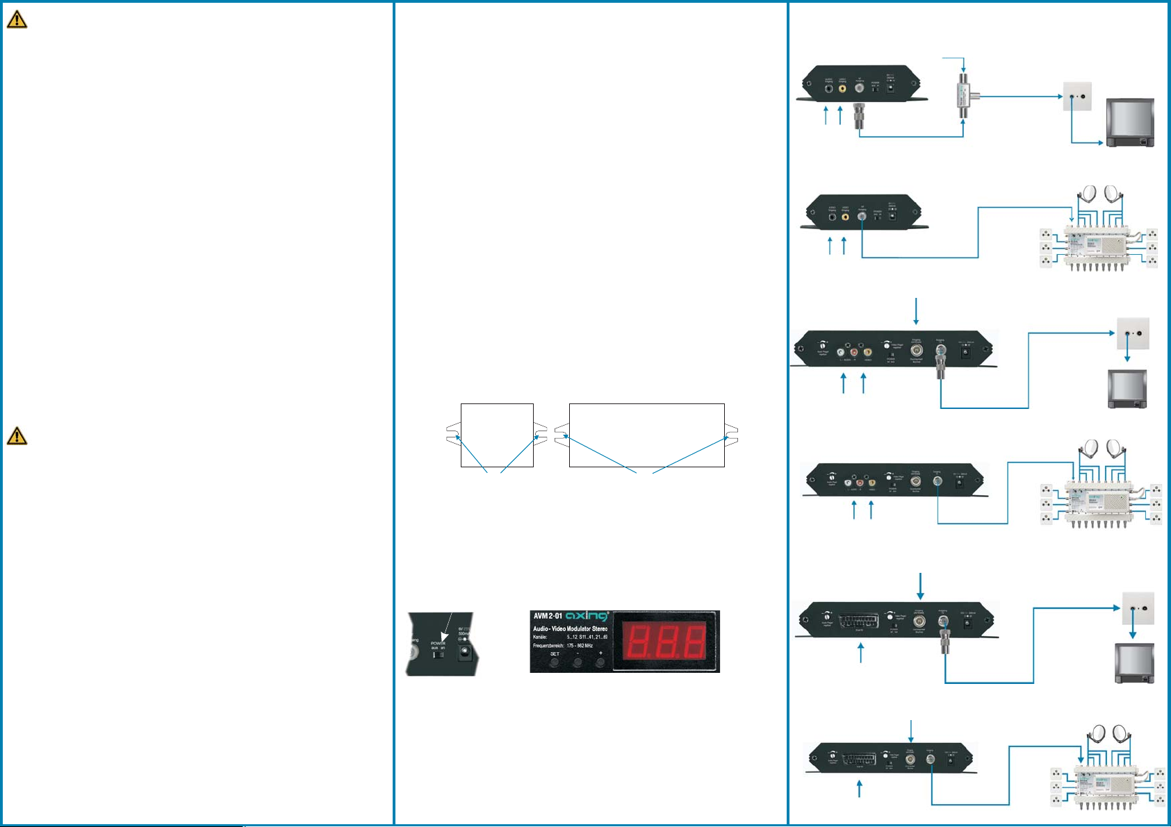
z.B. über Verteiler
e.g. through splitter
audio video
CCD, DVD, VCR
channel with A/V signal
z.B. über Multischalter
e.g. through multiswitch
audio video
CCD, DVD, VCR
z.B. über AVM 2-01
e.g. through AVM 2-01
audio level video level
audio video
CCD, DVD, VCR
z.B. über Multischalter
e.g. through multiswitch
audio level video level
audio video
CCD, DVD, VCR
z.B. über AVM 2-02
e.g. through AVM 2-02
audio level video level
audio video
DVD, VCR
z.B. über Multischalter
e.g. through multiswitch
audio level video level
audio video
DVD, VCR
Kanal mit A/V-Signal
Kanal mit A/V-Signal
channel with A/V signal
CATV/terr.
CATV/terr.
channel with A/V signal
CATV/terr.
CATV/terr.
Kanal mit A/V-Signal
channel with A/V signal
CATV/terr.
Kanal mit A/V-Signal
channel with A/V signal
Kanal mit A/V-Signal
Kanal mit A/V-Signal
channel with A/V signal
Signaleinspeisung
Signal feeding
Page 3
Caractéristiques techniques :
Gamme de fréquences 175…862 MHz
Canaux 5…12, S11…S41, 21…69
Ondulation ± 1,0 dB
Niveau de sortie 70 dBµV
Impédance de sortie 75 Ohm
Impédance d’entrée vidéo 75 Ohm
Impédance d’entrée audio 10 kOhm
Niveau d’entrée vidéo 1 V
Niveau d’entrée audio 1 V
Sortie des connexions F
AVM 1-02
Connexion vidéo Douille Cinch
Connexion audio (mono) Douilles Cinch
Consommation de courant 200 mA
Bloc d'alimentation 230 V~/50 Hz 6 V=/500 mA
Dimensions env. 105 x 91 x 36 mm
AVM 2-01
Connexion vidéo Douille Cinche
Connexion audio (stéréo) Douilles Cinch
Connecteurs HF (entrée) IEC
Consommation de courant 250 mA
Bloc d'alimentation 230 V~/50 Hz 12 V=/250 mA
Dimensions env. 225 x 91 x 36 mm
AVM 2-02
AVM 2-02 commeAVM 2-01, mais :
Connexion audio/vidéo SCART
Volume de livraison
Modulateur audio / vidéo AVM
Câble de connexion AV (AVM 1-02/2-01), Câble SCART, 1 m (AVM 2-02)
Bloc d'alimentation enfichable 230 V~/50 Hz, Adaptateur CFA 10-00 (F/IEC)
Ce symbole indique que, conformément à la directive DEEE
(2002/96/CE) et à la réglementation de votre pays, ce produit ne
doit pas être jeté avec les ordures ménagères. Vous devez le
déposer dans un lieu de ramassage prévu à cet effet, par exemple,
WEEE Nr.
DE14023300
SS
SS
un site de collecte officiel des équipements électriques et
électroniques en vue de leur recyclage ou un point d'échange de
produits autorisé qui est accessible lorsque vous faites l'acquisition
d'un nouveau produit du même type que l'ancien.
Pour obtenir plus d'informations sur les points de collecte des
équipements à recycler, contactez votre mairie, le service de
collecte des déchets, le plan DEEE approuvé ou le service
d'enlèvement des ordures ménagères.
Dit symbool geeft aan dat dit product in overeenstemming met de
AEEA-richtlijn (2002/96/EG) en de nationale wetgeving niet mag
worden afgevoerd met het huishoudelijk afval. Dit product moet
M'ODE D EMPLOI
Modulateur audio / vidéo
GEBRUIKSHANDLEIDING
AVM audio-/videomodulator
worden ingeleverd bij een aangewezen, geautoriseerd
WEEE Nr.
DE14023300
inzamelpunt, bijvoorbeeld wanneer u een nieuw gelijksoortig
product aanschaft, of bij een geautoriseerd inzamelpunt voor
hergebruik van elektrische en elektronische apparatuur.
Voor meer informatie over waar u uw afgedankte apparatuur kunt
inleveren voor recycling kunt u contact opnemen met het
gemeentehuis in uw woonplaats, de reinigingsdienst, of het
afvalverwerkingsbedrijf. U kunt ook het schema voor de afvoer van
afgedankte elektrische en elektronische apparatuur (AEEA)
raadplegen.
Technische gegevens :
Frequentiebereik 175…862 MHz
Kanalen 5…12, S11…S41, 21…69
Rimpel ± 1,0 dB
Uitgangsniveau 70dBµV
Uitgangsimpedantie 75 Ohm
Video ingangsimpedantie 75 Ohm
Audio ingangsimpedantie 10 kOhm
Video ingangsniveau 1 V
Audio ingangsniveau 1 V
Aansluiting uitgang F-female
AVM 1-02
Aansluiting video cinch-bus
Aansluiting audio (mono) cinch-bussen
Stroomopname 200 mA
Netvoeding 230 V~/50 Hz 6 V=/500 mA
Afmetingen ca. 105 x 91 x 36 mm
AVM 2-01
Aansluiting video cinch-bus
Aansluiting audio (stereo) cinch-bussen
Aansluiting HF (ingang) IEC-bus
Stroomopname 250 mA
Netvoeding 230 V~/50 Hz 12 V=/250 mA
Afmetingen ca. 225 x 91 x 36 mm
AVM 2-02
AVM 2-02 alsAVM 2-01, echter:
aansluiting audio/video SCART
Leveringsomvang
AVM audio-/videomodulator
AV-aansluitkabel (AVM 1-02/2-01), SCART-kabel, 1 m
Stekkervoeding 230 V~/50 Hz, CFA10-00 adapter (F-stekker op IEC-stekker)
(AVM 2-02)
SS
SS
Hersteller
AXING AG
Gewerbehaus Moskau
CH-8262 Ramsen
EWR-Kontaktadresse
Bechler GmbH
Am Rebberg 44
D-78239 Rielasingen
AVM 1-02
FR
NL
AVM 2-01/-02
Etat actuel 2013-08-01- Sous réserve de modifications de construction et de type
Stand 2013-08-01 - constructie- en typewijziging voorbehouden - geen aansprakelijkheid voor drukfouten
Nous n’assumons aucune responsabilité pour les erreurs d'impression
Page 4
Consignes de sécurité :
· L'installation de l'appareil et les réparations sur ce dernier doivent être effectuées exclusivement par
un spécialiste dans le respect des directives VDE. Aucune responsabilité ne sera assumée en cas
d'installation et de mise en service incorrectes.
· Avant d'ouvrir l'appareil, retirer la fiche de secteur ou couper l'alimentation en courant, sinon, il y a
danger de mort. Cela s'applique également lorsque vous nettoyez l'appareil ou effectuez des travaux
sur les raccordements.
· Utilisez uniquement le bloc d‘alimentation enfichable contenu dans le volume de livraison ! Ne
remplacez jamais des pièces et n’effectuez aucune modification sur le bloc d’alimentation enfichable.
Sinon, il y a un risque de mort dont nous déclinons toute responsabilité.
· Dans la mesure où il existe un fusible interchangeable, la prise de secteur doit être retirée avant de
remplacer le fusible. Ne remplacer les fusibles défectueux que par des fusibles conformes aux
normes et ayant la même valeur nominale.
· L'appareil ne doit être utilisé que dans des locaux secs. L'utilisation dans des locaux humides ou à
l'extérieur présente un risque de courts-circuits (attention : risque d'incendie) ou d'électrocution
(attention : danger de mort)
· Prévoyez un lieu de montage ou d'implantation permettant, en cas de situations de danger,
d'atteindre facilement la fiche de secteur afin de pouvoir la débrancher de la prise de courant.
Choisissez un lieu de montage ou d'implantation de telle sorte que des enfants ne puissent pas jouer
avec l'appareil et ses raccordements sans surveillance. Le lieu de montage ou d'implantation doit
permettre une pose sûre de tous les câbles raccordés. Les câbles d'alimentation électrique et câbles
d'alimentation ne doivent pas être endommagés ou écrasés par des objets de toute nature qu'ils
soient.
· Choisissez un lieu de montage ou d'implantation sur lequel des liquides ou objets ne pourront en
aucun cas atteindre l'appareil (par ex. eau condensée, fuite provenant du toit, eau d'arrosage, etc.).
· N'exposez jamais l'appareil au rayonnement direct du soleil et évitez qu'il se trouve à proximité de
sources de chaleur (par ex. radiateurs, autres appareils électriques, cheminée, etc.). Veillez
impérativement à ce que les appareils équipés de refroidisseurs ou ayant des fentes d'aération ne
soient en aucun cas recouverts ou obstrués. Par ailleurs, veillez à assurer une circulation d'air
appropriée et suffisante autour de l'appareil. Vous pourrez ainsi éviter des endommagements
éventuels de l'appareil ainsi que le risque d'incendie causé par une surchauffe. Veillez
impérativement à ce que les câbles ne soient pas à proximité de sources de chaleur (par ex.
radiateurs, autres appareils électriques, cheminée, etc.).
Domaine d'application / description du produit :
Les appareils conviennent exclusivement à la distribution de signaux de radio et de télévision
dans la maison de même que des signaux multimédia ! Il ne sera accordé aucune garantie si
l'appareil fait l'objet d'une utilisation autre que celle indiquée !
Le modulateur audio/vidéo module un signal A/V en un canal HF pour la connexion à un
téléviseur ou pour la distribution dans une installation collective.
Une caméra CCD, un magnétoscope, un lecteur de DVD ou un appareil similaire peuvent
être connectés à l'entrée. La surveillance d'une chambre d'enfant, de l'entrée d'une maison
ou de toute autre zone sensible est rendue possible grâce à une caméra.
Au niveau de la sortie, une très simple programmation permet de régler un canal sans
assignation.
Gebruiksgebied/Productbeschrijving:
De apparaten zijn uitsluitend geschikt om radio- en tv-signalen resp. multimediasignalen in
huis te verdelen! Wordt een apparaat anders gebruikt, wordt geen garantie gegeven.
De audio-video-modulator moduleert een A/V-signaal naar een HF-kanaal voor aansluiting op
een tv-apparaat of voor doorgifte in een GAI/CAI.
Op de ingang wordt bijvoorbeeld een CCD-camera, een videorecorder, een DVD-player of
een vergelijkbaar apparaat aangesloten. Zo kann met een camera een kinderkamer, een
huisingang of een ander sensibel gebied worden bewaakt.
Aan de uitgangszijde wordt door middel van een simpele programmering een kanaal
ingesteld, dat niet bezet is.
Montage :
Utiliser les vis de montage fournies avec l'appareil et les trous de montage prévus sur les
appareils 1. 1
Montage:
Gebruik de bij het apparaat bijgevoegde montageschroeven en de montagegaten aan de
apparaten .1
par ex. à l'aide d'un distributeur
bijv. via verdeler
CCD, DVD, VCR
Câble bande large, terrestre
CAI/terr.
par ex. à l'aide d'un commutateur multiple
bijv. via multischakelaar
CCD, DVD, VCR
par ex. à l'aide du AVM 2-01
bijv. viaAVM 2-01
Niveau audio
Audio-niveau
CCD, DVD, VCR
Niveau vidéo
Video-niveau
Câble bande large, terrestre
CAI/terr.
Transmission du signal
Signaaltoevoer
Veiligheidsaanwijzingen:
· De installatie van het apparaat en reparaties aan het apparaat mogen uitsluitend door een vakman
onder in achtneming van de geldende VDE richtlijnen worden uitgevoerd. Bij een niet vakkundige
installatie en ingebruikname wordt geen aansprakelijkheid aanvaard.
· Voor het openen van het apparaat stekker uit het stopcontact trekken resp. stroomtoevoer
onderbreken, anders bestaat levensgevaar. Dit geldt ook, wanneer u het apparaat reinigt of aan de
aansluitingen werkt.
· Gebruik alleen de stekkervoeding die bij de levering inbegrepen is! Er mogen in geen geval delen van
de stekkervoeding vervangen of veranderingen eraan uitgevoerd worden. Er bestaat anders
levensgevaar, waarvoor geen aansprakelijkheid aanvaardt wordt.
· Indien een vervangbare zekering voorhanden is, dient voor het vervangen van de zekering de stekker
uit het stopcontact te worden getrokken. Defecte zekeringen alleen door zekeringen met dezelfde
norm en dezelfde nominale waarde vervangen.
· Het apparaat mag alleen in droge ruimten worden gebruikt. In vochtige ruimten of buitenshuis bestaat
gevaar voor kortsluitingen (let op: brandgevaar) of elektrische schokken (let op: levensgevaar).
· Plant u de montage- resp. plaats van bestemming zo, dat u in gevaarlijke situaties de stroomstekker
makkelijk kunt bereiken en uit het stopcontact kunt trekken. Kiest de plaats van montage of opstelling
zo, dat kinderen niet zonder toezicht met het apparaat en de aansluitingen kunnen spelen. Op de
plaats van montage of opstelling moet een veilig verleggen van de aangesloten kabels mogelijk zijn.
Stroomvoorzieningskabel alsmede toevoerkabel mogen niet door een of andere voorwerpen
beschadigd of ingeklemd worden.
· Kies een plaats van montage of opstelling waar in geen geval vloeistoffen of voorwerpen in het
apparaat kunnen terechtkomen (bijv. condenswater, lekken in het dak, gietwater).
· Stel het apparaat nooit bloot aan directe zonnestraling en vermijd de directe nabijheid van
warmtebronnen (bijv. radiatoren, ander elektrische apparaten, schoorsteen etc.). Bij apparaten, die
koelplaten of ventilatiegleuven hebben, moet er daarom beslist op worden gelet, dat deze in geen
geval afgedekt of dichtgebouwd worden. Zorg bovendien voor een ruim bemeten luchtcirculatie om
het apparaat. Daarmee vermijdt u mogelijke beschadigingen aan het apparaat en brandgevaar door
oververhitting. Let er beslist op dat kabels niet in de nabijheid van warmtebronnen (bijv. radiatoren,
andere elektrische apparaten, schoorsteen etc.) komen.
11
Programmation du canal de sortie :
Le Modulateur "AVM" est mis en marche avec le commutateur par l'arrière. Tenir
appuyée la touche SET pendant env. 3 secondes jusqu'à ce que la DELde l'affichage
commence à clignoter. Régler maintenant le canal souhaité à l'aide de la touche « + » ou
« - ». L'affichage arrête de clignoter env. 3 secondes plus tard et le canal souhaité est
réglé.
commutateur POWER
POWER-schakelaar
Affichage DEL
LED-indicatie
Touche SET SET-knop
Programmering van het uitgangssignaal
AVM met de POWER-schakelaar op de achterkant inschakelen. SET-knop ca. 3 seconden
ingedrukt houden tot de LED-indicatie begint te knipperen. Nu met de "+" of "-" knop het
gewenste kanaal instellen. De indicatie houdt na 3 seconden op te knipperen en het gewenste
kanaal is ingesteld.
par ex. à l'aide d'un commutateur multiple
bijv. via multischakelaar
Niveau audio
Audio-niveau
Niveau vidéo
Video-niveau
audio video
CCD, DVD, VCR
Kanal mit A/V-Signal
channel with A/V signal
par ex. à l'aide du AVM 2-02
bijv. viaAVM 2-02
Niveau audio
Audio-niveau
DVD, VCR
Niveau vidéo
Video-niveau
Câble bande large, terrestre
CAI/terr.
par ex. à l'aide d'un commutateur multiple
bijv. via multischakelaar
Niveau audio
Audio-niveau
DVD, VCR
Niveau vidéo
Video-niveau
Câble bande large, terrestre
CAI/terr.
 Loading...