

Page 1
i
MR-102N
English Version 3.0.0
Page 2

i
CONTENT
CHAPTER1 INTRODUCTION .............................................................................................................. 1
1.1 BENEFITS .................................................................................................................................. 1
1.2 PACKAGE CONTENT ............................................................................................................. 2
CHAPTER2 HARDWARE INSTALLATION ........................................................................................... 3
2.1 PANEL LAYOUT ....................................................................................................................... 3
2.1.1 Product Picture ............................................................................................................. 3
2.1.2 Panel LEDs ..................................................................................................................... 4
2.1.3 Side Panel ...................................................................................................................... 5
2.1.4 Side Panel ...................................................................................................................... 5
2.2 PROCEDURE FOR HARDWARE INSTALLATION .................................................................... 6
2.2.1 Install the Battery .......................................................................................................... 6
2.2.2 Power On ....................................................................................................................... 6
2.2.3 Setup LAN Connection ................................................................................................ 6
2.2.4 Setup WAN Connection .............................................................................................. 6
CHAPTER3 NETWORK SETTINGS FOR YOUR PC ............................................................................. 7
3.1 FOR WINDOWS XP USERS ...................................................................................................... 7
3.2 FOR WINDOWS 2000 USERS .................................................................................................. 9
3.3 FOR WINDOWS 98/ME USERS ............................................................................................. 11
3.4 FOR WINDOWS7 USERS ....................................................................................................... 13
CHAPTER4 ACCESSING THE AXIMCom MOBILE ROUTER ..........................................................15
4.1 START-UP AND LOG-IN ........................................................................................................ 15
CHAPTER5 BASIC SETTINGS ............................................................................................................16
5.1 WAN SETUP ........................................................................................................................... 16
5.1.1 DHCP (automatic IP address assignment) ............................................................. 18
5.1.2 Static (Fixed IP address assignment) ....................................................................... 19
5.1.3 PPPoE (connected by username/password) ........................................................ 20
5.1.4 VPN Client .................................................................................................................... 21
5.1.5 Mobile WAN (connected by information related to what your ISP needs) ..... 22
5.1.6 BlackBerry .................................................................................................................... 24
5.1.7 Windows Mobile / Google Android Phones .......................................................... 25
5.1.8 HSPA+ Super Speed ................................................................................................... 26
5.1.9 Apple iPhone .............................................................................................................. 28
5.2 WAN DETECT ........................................................................................................................ 29
5.3 LAN SETUP ............................................................................................................................. 30
5.4 DHCP SERVER SETUP ............................................................................................................ 31
5.5 DDNS SETUP .......................................................................................................................... 32
Page 3

ii
5.6 MAC ADDRESS CLONE SETUP ............................................................................................ 34
5.7 TIME SETUP ............................................................................................................................ 35
CHAPTER6 WIRELESS SETTINGS ......................................................................................................36
6.1 BASIC SETUP .......................................................................................................................... 36
6.1.1 Settings ......................................................................................................................... 36
6.1.2 SSID Settings................................................................................................................. 38
6.1.3 WEP ............................................................................................................................... 40
6.1.4 WPA Pre-shared Key / WPA2 Pre-shared Key ........................................................ 41
6.1.5 WPA / WPA2(RADIUS) ................................................................................................ 42
6.2 ADVANCED SETUP ............................................................................................................... 43
6.3 WDS SETUP ............................................................................................................................ 45
6.4 UNIVERSAL REPEATER SETUP ............................................................................................... 46
6.5 WPS SETUP ............................................................................................................................. 47
CHAPTER7 SECURITY SETTINGS ......................................................................................................49
7.1 FIREWALL SETUP .................................................................................................................... 49
7.2 ACCESS CONTROL LIST (ACL)SETUP .................................................................................. 51
7.2.1 ALC setting .................................................................................................................. 51
7.3 MAC ACCESS CONTROL SETUP ......................................................................................... 54
7.4 OpenDNS SETUP .................................................................................................................. 56
7.4.1 OpenDNS Settings ...................................................................................................... 56
7.5 WEB FILTERING SETUP ........................................................................................................... 57
7.5.1 Added Web Filtering Rules ........................................................................................ 58
CHAPTER8 APPLICATIONS SETTINGS .............................................................................................59
8.1 PORT RANGE FORWARD SETUP ......................................................................................... 59
8.1.1 Port Range Forward Settings .................................................................................... 60
8.1.2 Add Port Range Forwarding Rule ............................................................................ 61
8.2 VIRTUAL HOST SETUP ............................................................................................................ 62
8.2.1 Virtual Host Settings .................................................................................................... 62
8.2.2 Add Virtual Host .......................................................................................................... 63
8.3 STREAMING/VPN PASS-THROUGH ..................................................................................... 64
8.4 UPnP/NAT-PMP SETUP ......................................................................................................... 65
CHAPTER9 AirCloud .......................................................................................................................66
9.1 DRIVE SETUP .......................................................................................................................... 66
CHAPTER10 ADMIN ..........................................................................................................................67
10.1 MANAGEMENT ..................................................................................................................... 67
10.2 SYSTEM UTILITIES .................................................................................................................... 69
10.3 LOG ....................................................................................................................................... 71
CHAPTER11 STATUS ...........................................................................................................................72
11.1 ROUTER INFORMATION ....................................................................................................... 72
Page 4

iii
11.2 USER/DHCP ........................................................................................................................... 74
11.3 USER/ CURRENT .................................................................................................................... 75
Page 5

1
CHAPTER1 INTRODUCTION
AXIMCom’s Mobile Router Series is designed for heavy network users, renters, mobile offices, outdoor hotspots
and anyone using 3G/4G as a replacement for a fixed line connection. By simply connecting a 3G/4G modem,
you can create a mobile broadband network anytime, anywhere, for a group of users and devices to share.
Since the mobile broadband is shared, the ‘cost per user/device’ is then consequently reduced. Furthermore,
AXIMCom’s Mobile Router Series also supports 802.11n technology, so you can enjoy the fast and large area
wireless coverage!
1.1 BENEFITS
True Mobile Broadband Sharing (Support 3G/4G + 802.11n + xDSL/cable modem)
AXIMCom Mobile Router supports multiple broadband technologies, including 3G/4G, 802.11n and
xDSL/cable modem. You can create a mobile broadband using a 3G/4G modem or switch to fixed line
connection using xDSL/cable modem. It also supports the latest 802.11n technology, offering a true mobile
broadband sharing solution!
Complete 3G/4G Modem Support
AXIMCom Mobile Router provides complete support for all major 3G/4G USB modems. Simply use your
existing 3G/4G modem and service provider to create a mobile broadband sharing environment. (Find our
compatibility at the end of the user manual.)
Energy Saving
With the low power consumption SOC chip adopted, AXIMCom Mobile Router provides a lower power
consumption ability which saves not only energy, but also our environment.
Session Manager
AXIMCom Mobile Router supports up to 10000 fast recycling sessions in order to guarantee stable network
connection and to accommodate more users/applications in the network.
3G/4G APN and PIN Code Support
AXIMCom Mobile Router supports 3G/4G APN and PIN code in order to prevent unauthorized access to
your Mobile Router and to increase the security levels of your mobile broadband hot-spot.
Universal Repeater
With the use of the University Repeater function, AXIMCom Mobile Router can increase your wireless
coverage and eliminate dead spots in just a few steps. Hence, this allows users to be free from the hassles
from the extremely complicated WDS settings. (Note: you need at least 2 units to use this function.)
Page 6

2
1.2 PACKAGE CONTENT
One AXIMCom 3G/4G Mobile Router
One User Manual CD
One Quick Installation Guide
One Power Adaptor
One Li-ion Battery Pack
Page 7
3
CHAPTER2 HARDWARE INSTALLATION
2.1 PANEL LAYOUT
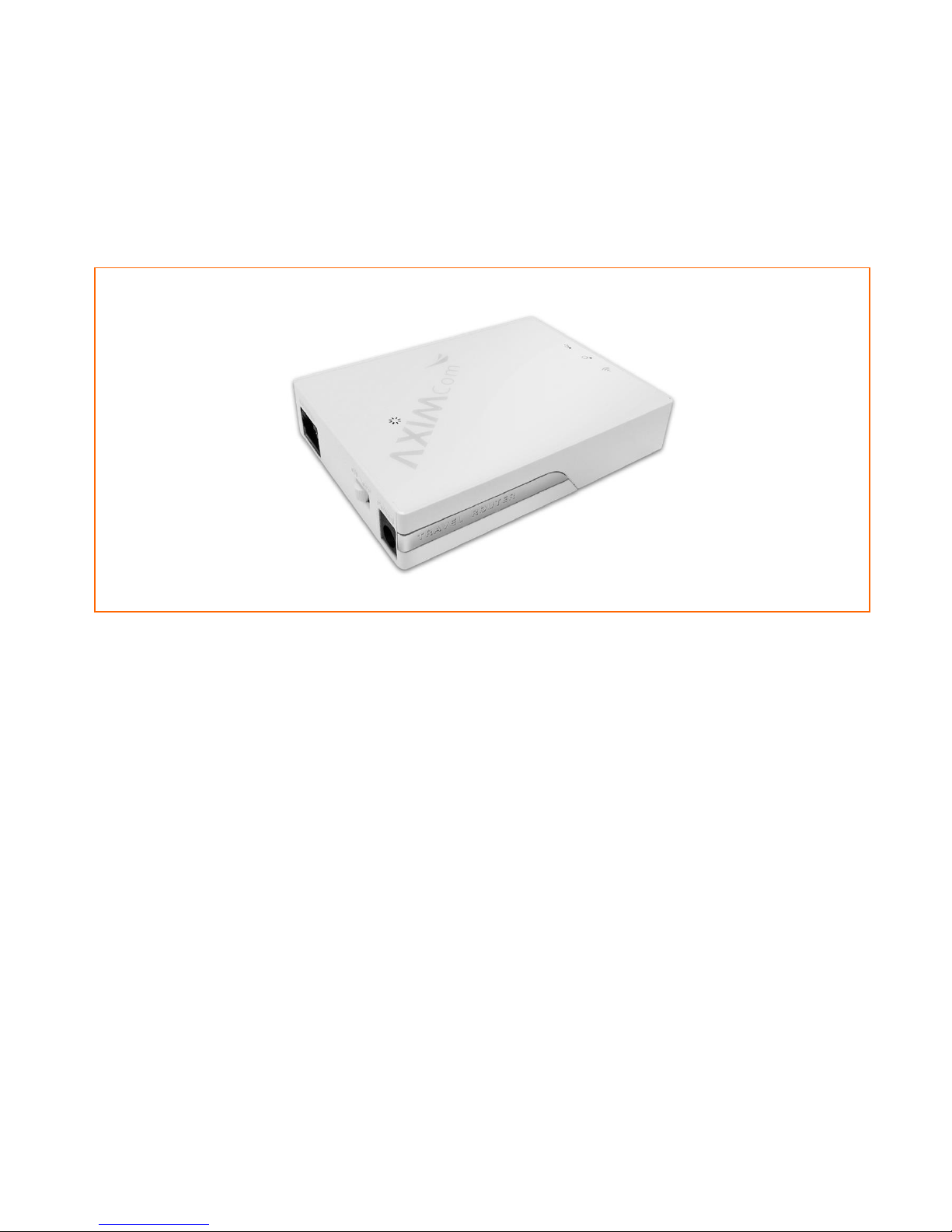
2.1.1 Product Picture
Page 8

4
2.1.2 Panel LEDs
LED
Function
Color
Status
Description
USB/STATUS
USBActivity/
Router Status
Indication
Green
On
The Mobile WAN is connected.
Off
USB Dongle/Modem is not inserting in.
Fast Blinking
The USB device is activating or ejecting.
Slow Blinking
System is booting up and will turn off after booting.
Please contact AXIMCom if the LED is continuous in this
status.
WLAN
Wireless
Activity
Green
On
Wireless connection is enabled.
Off
Wireless connection is disabled.
ETHERNET
Ethernet
Link
Green
On
The Ethernet port is linked.
Off
The Ethernet port is not linked.
Blinking
Data is being transmitted via the Ethernet port.
Power
Power
Indication
Green
/Red
Green On
Red On
Battery is charging.
All Off
Power is off.
Green On
Power is on and battery is full.
Green Blinking
Power is on and battery is consuming.
Green On
Red Blinking
Power is on. No battery is inserted or battery fault.
Red On
Low battery.
Page 9
5
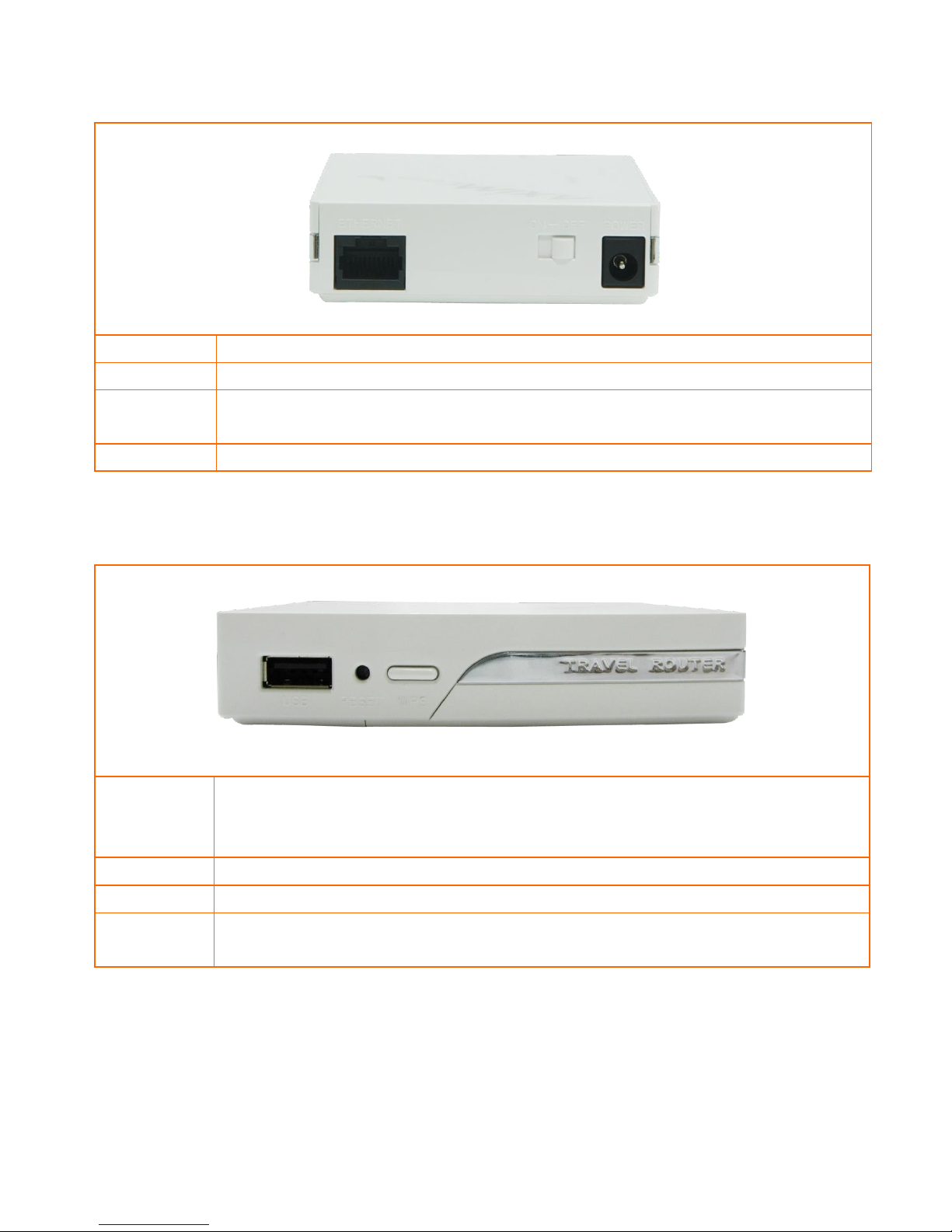
2.1.3 Side Panel
Ports/Switch
Description
Power
Power inlet
ETHERNET
The port for connecting your DSL or Cable Modem when configures as WAN; the port for
connecting your computers, printer or other devices when configure as LAN
ON-OFF Switch
Switch ON/OFF to turn on/off the router.
2.1.4 Side Panel
8
961j6Port/Button
Description
USB Port
For connecting you USB dongle/modem to establish a Mobile WAN connection.
WPS
The button for ejecting the USB 3G/4G modem safely.
Reset
Press “Reset” button for 2 sec and then release it, AXIMCom Mobile Router will be configured
to factory default value.
Page 10
6
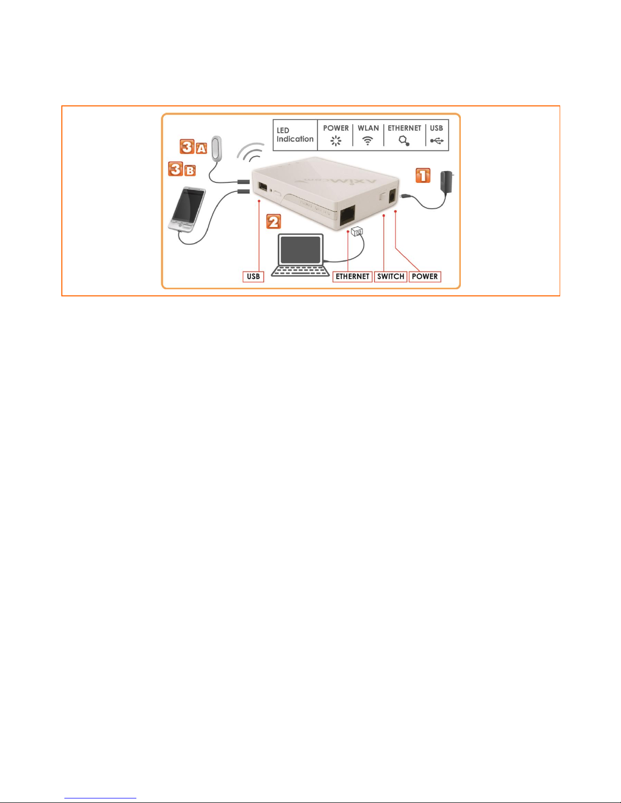
2.2 PROCEDURE FOR HARDWARE INSTALLATION
2.2.1 Install the Battery
Open the back cover and insert the provided battery pack.
2.2.2 Power On
Take the provided power adapter. Plug one end into Mobile Router’s DC power port and the other end into a
power outlet. Switch On the power switch, AXIMCom Mobile Router’s STATUS LED will be blinking and soon enter
the working mode when its STATUS LED is off.
2.2.3 Setup LAN Connection
Take an Ethernet cable. Plug one end of the cable into your computer’s network port and the other end into
one of AXIMCom Mobile Router’s LAN ports.
2.2.4 Setup WAN Connection
Please plug the 3G/4G USB modem into Mobile Router’s USB port, the USB LED will blink. The WAN connection is
established when the USB LED is SOLID.
Page 11
7
CHAPTER3 NETWORK SETTINGS FOR YOUR PC
Before using the AXIMCOM Mobile Router, you have to configure your network settings in your computer. You
can either use DHCP or Static IP for your TCP/IP Settings.
* DHCP is recommended due to its relative ease in configuration.
3.1 FOR WINDOWS XP USERS
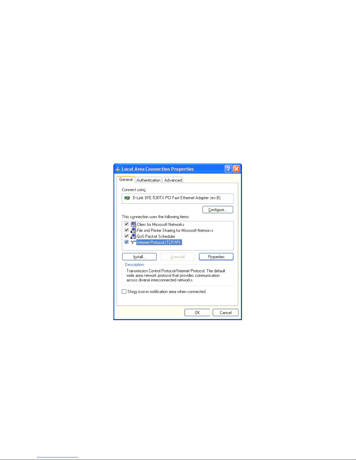
1. Select Start > Settings > Network Connections
2. Click on Local Area Connection and choose Properties. You will now see the following screen.
3. Select Internet Protocol (TCP/IP) for your network card.
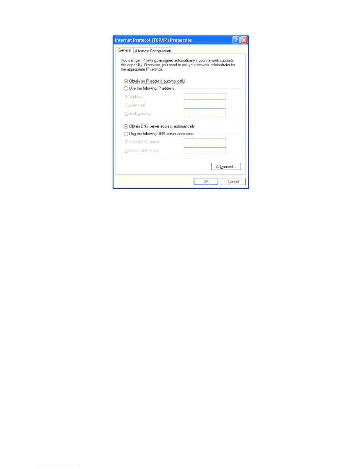
4. Click on Properties. You will see the following screen.
Page 12
8
5. Enable DHCP or Static IP:
To use DHCP
Select Obtain an IP Address automatically and Obtain DNS server address automatically.
Then click OK. AXIMCom Mobile Router will now assign an IP address to your computer.
To use Static IP
Select Use the following IP address and enter the followings.
IP address: 192.168.1.x (x could be from 2 ~ 254)
Subnet mask: 255.255.255.0
Default gateway: 192.168.1.1
Now select Use the following DNS server addresses and enter the following.
Preferred DNS server: 192.168.1.1.Then click OK.
6. You have now finished the network settings for your computer. Please go to Chapter 4 to continue.
Page 13
9
3.2 FOR WINDOWS 2000 USERS
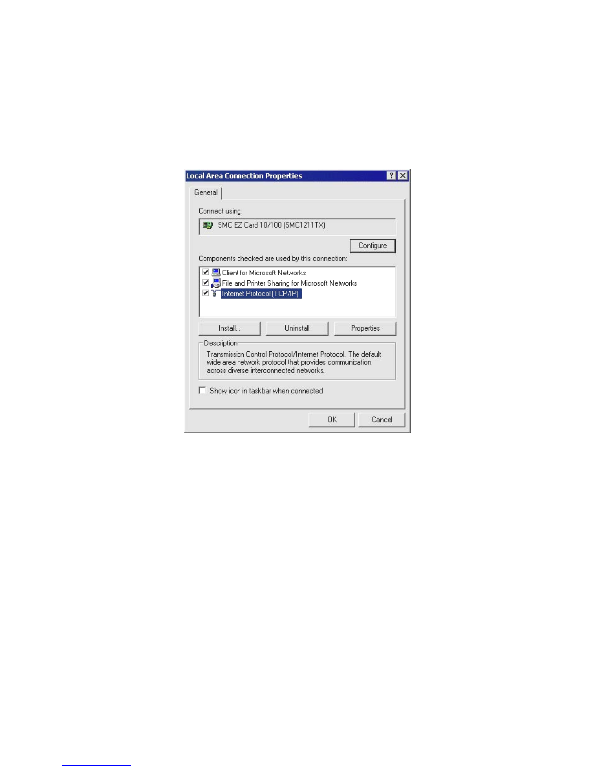
1. Select Start > Settings > Network and Dial-up Connection
2. Right click on the Local Area Connection and select Properties. You will see the following screen.
3. Select the Internet Protocol (TCP/IP) for your network card.
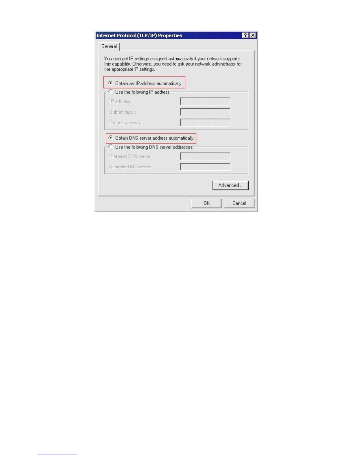
4. Click on Properties. You will see the following screen.
Page 14
10
5. Enable DHCP or Static IP:
To use DHCP
Select Obtain an IP Address automatically and Obtain DNS server address automatically.
Then click OK. AXIMCom Mobile Router will now assign an IP address to your computer.
To use Static IP
Select Use the following IP address and enter the followings.
IP address: 192.168.1.x (x could be from 2 ~ 254)
Subnet mask: 255.255.255.0
Default gateway: 192.168.1.1
Now select Use the following DNS server addresses and enter the following. Preferred DNS server: 192.168.1.1
Then click OK.
6. You have now finished the network settings of your computer. Please go to Chapter 4 to continue.
Page 15
11
3.3 FOR WINDOWS 98/ME USERS
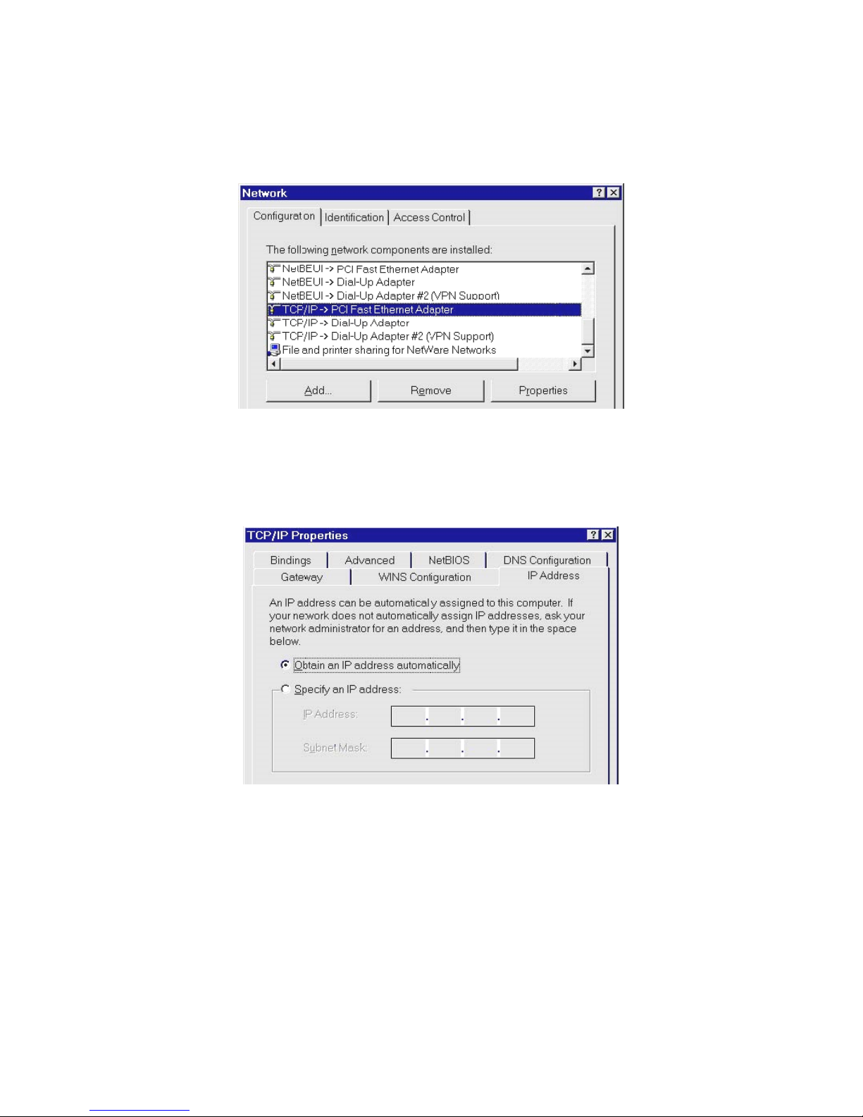
1. Select Start > Settings > Network. You will see the following screen.
2. Select TCP/IP -> PCI Fast Ethernet Adapter for your network card.
3. Click on Properties. You will now the following screen.
4. Enable DHCP or Static IP:
To use DHCP
Select Obtain an IP Address automatically.
Then click OK. AXIMCom Mobile Router will now assign an IP address to your computer.
Page 16
12
To use Static IP
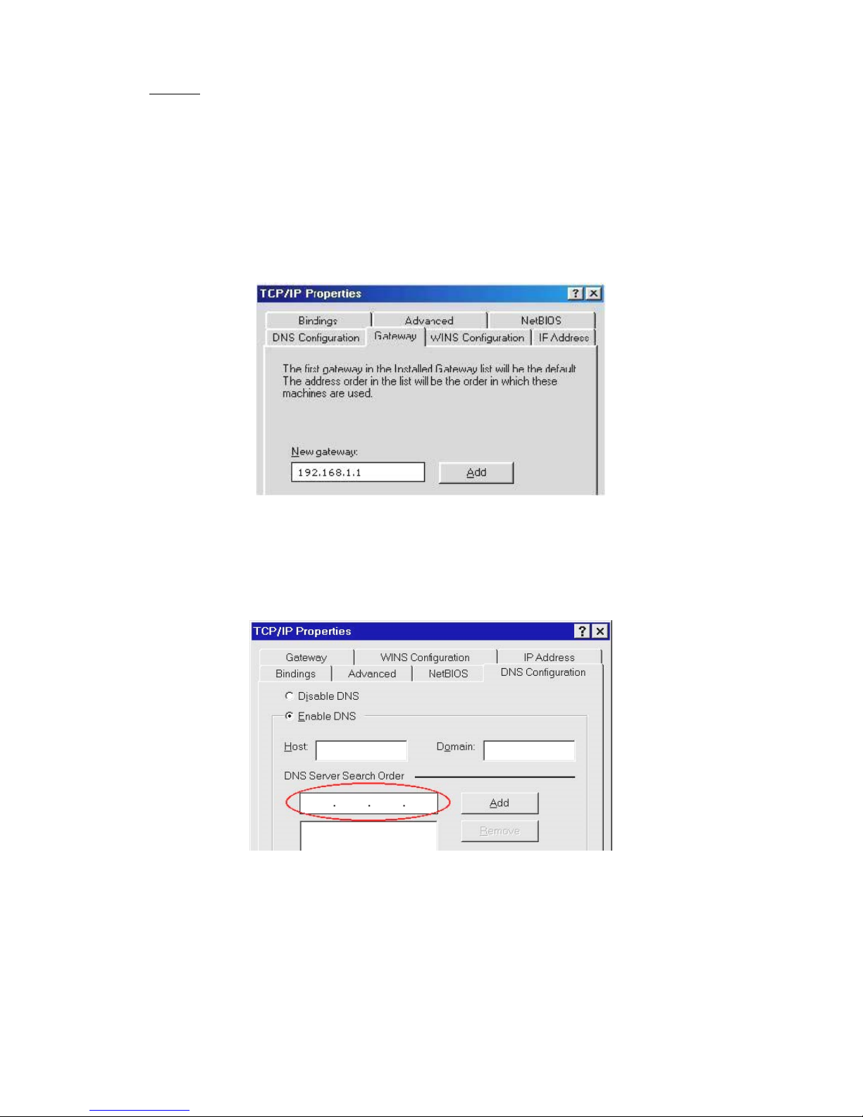
Select Specify an IP address and enter the followings.
IP address: 192.168.1.x (x could be from 2 ~ 254)
Subnet mask: 255.255.255.0
Now click on Gateway tab. You will see the following screen.
Enter 192.168.1.1 inNew Gateway, and click Add.
Now click on the DNS Configuration tab. You will see the following screen.
Enter 192.168.1.1 in DNS Server Search Order and click Add.
Then click OK.
5. You have now finished the network settings of your computer. Please go to Chapter 4 to continue.
Page 17
13
3.4 FOR WINDOWS7 USERS
1. Select Start >Control Panel> Network and Internet> Network and Sharing Center >Change Adapter
Settings
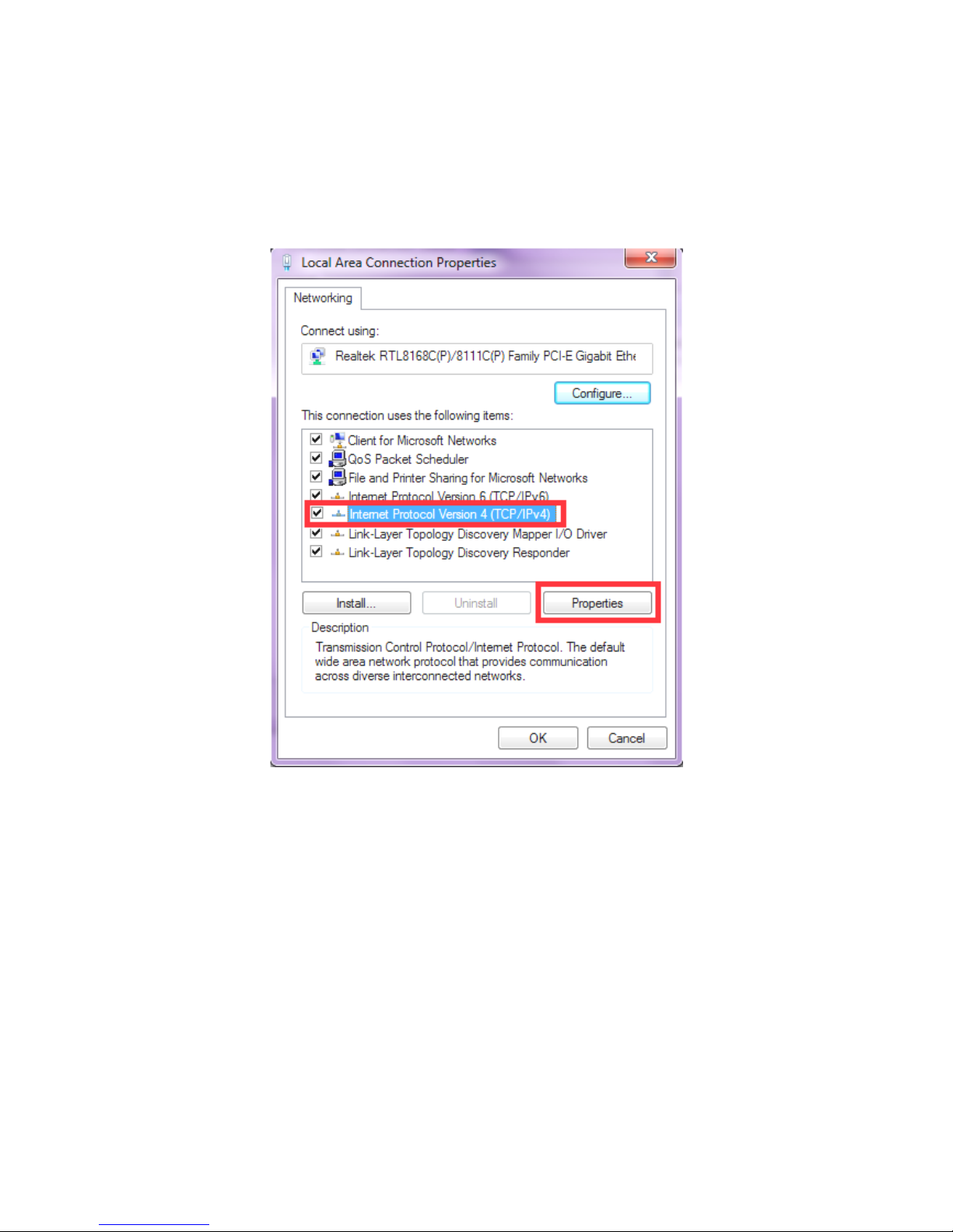
2. Click on Local Area Connection and choose Properties. You will now see the following screen.
3. Select Internet Protocol (TCP/IP) for your network card.
4. Click on Properties. You will see the following screen.
Page 18
14
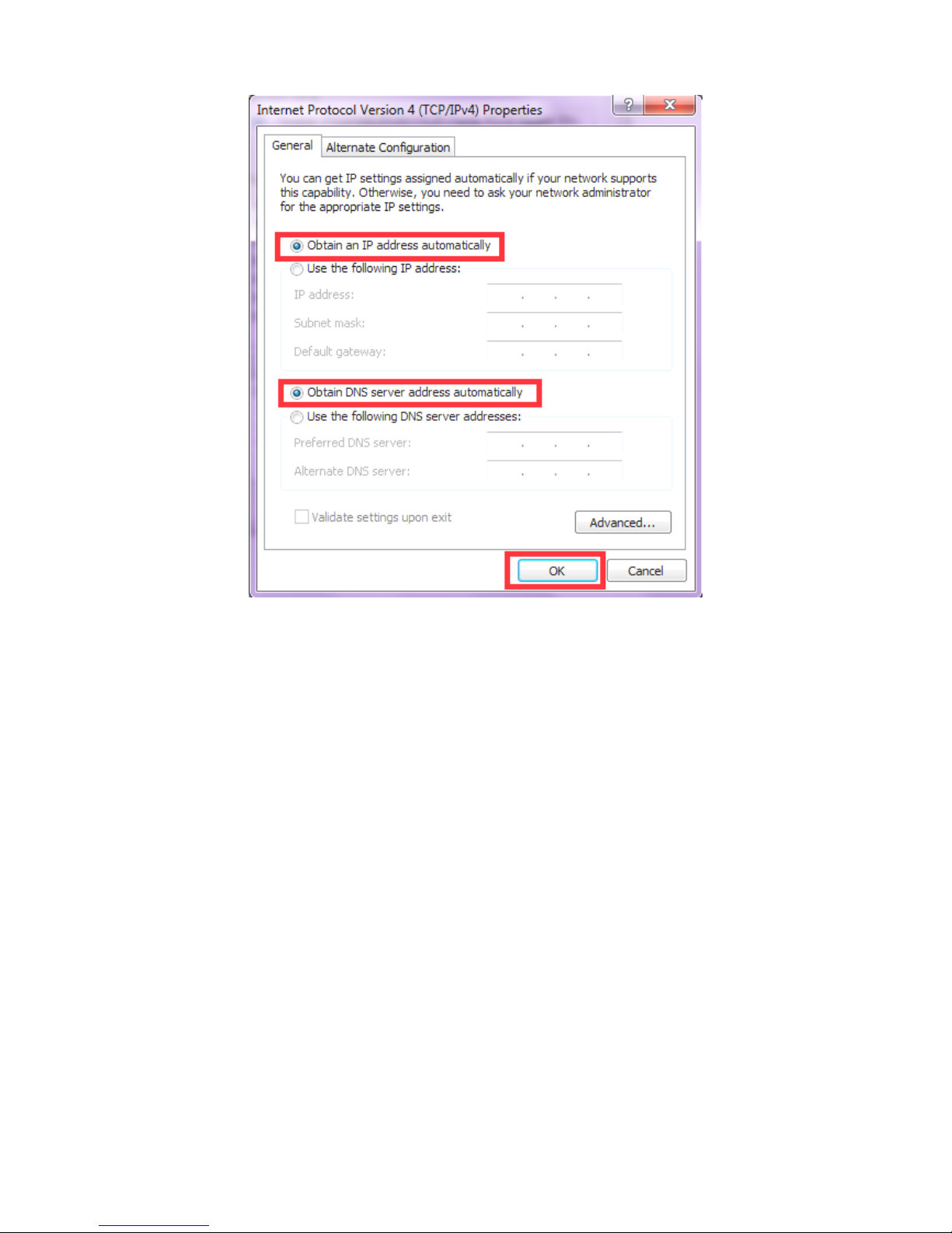
5. Enable DHCP or Static IP:
Page 19
15
CHAPTER4 ACCESSING THE AXIMCom MOBILE ROUTER
For Windows XP/2000 users, your computer should have obtained an IP address after configuring the network
settings on your computer. Now you need to configure your AXIMCom Mobile Router.
4.1 START-UP AND LOG-IN
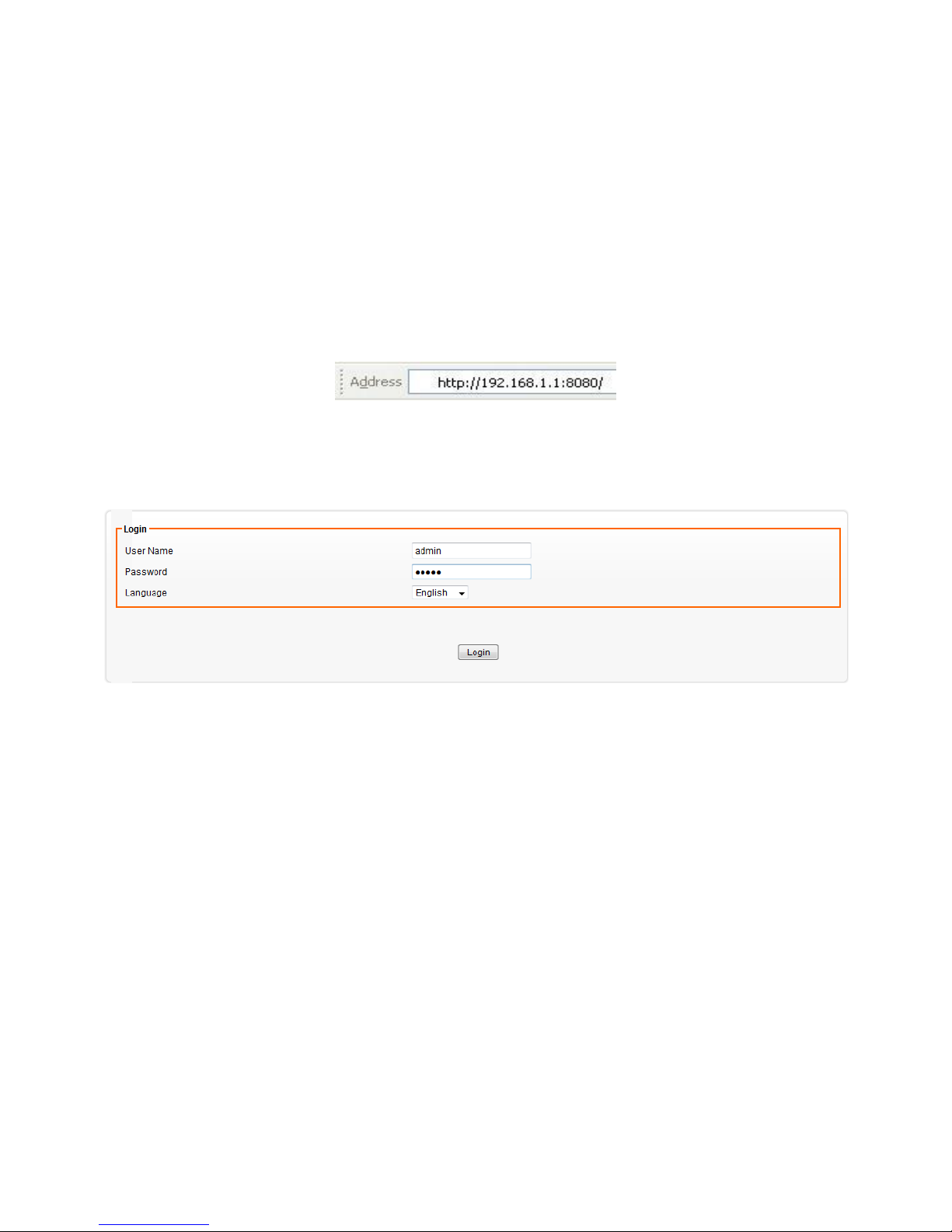
Open your WEB browser. In the address box, enter [HTTP://192.168.1.1:8080]
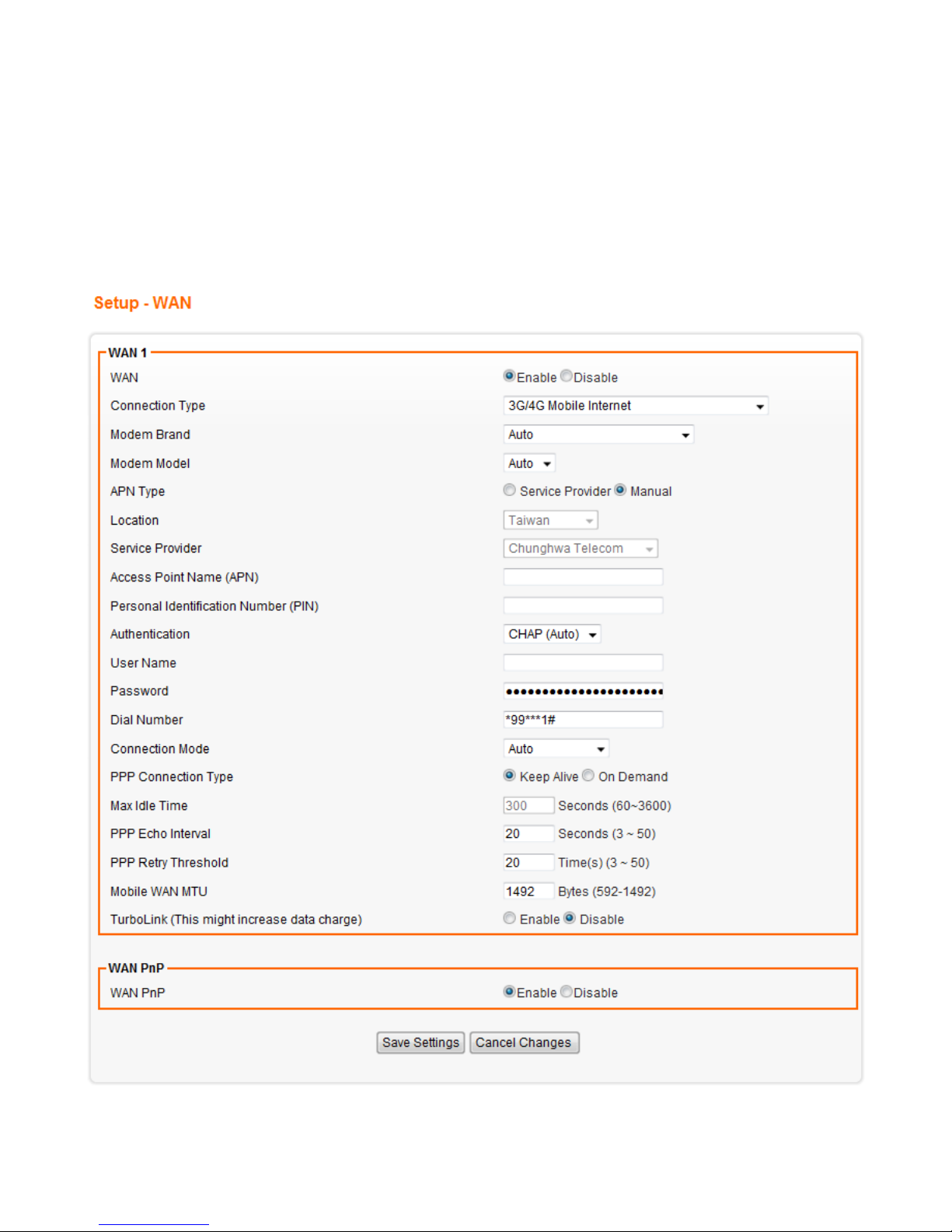
When you successfully connect to the configuration interface for AXIMCom Mobile Router, the login screen will
pop up.
Enter your username as [admin] and your password as [admin]. You will now see the status page of AXIMCom
Mobile Router.
Page 20
16
CHAPTER5 BASIC SETTINGS
5.1 WAN SETUP
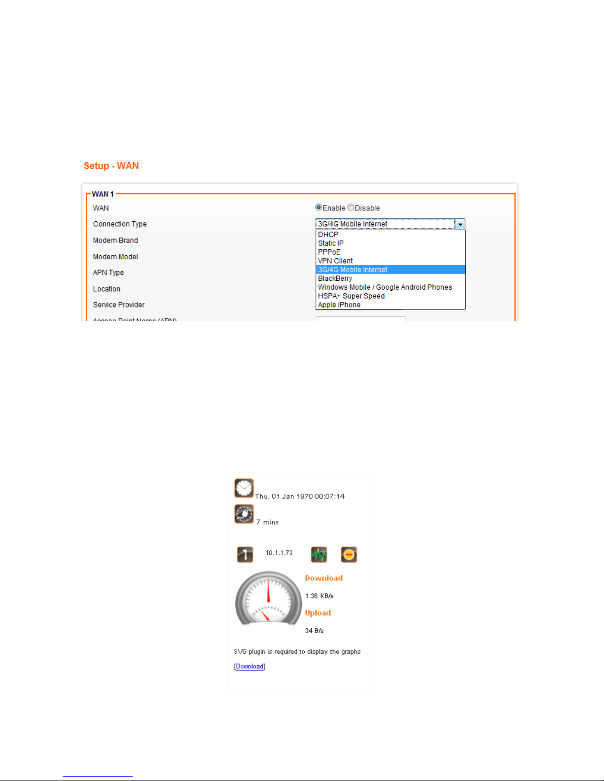
1. Click on [Setup] - [WAN] tab. You will see the following screen.
Page 21
17
2. WAN Settings:
AXIMCom Mobile Router supports eight connection types: DHCP, Static IP, PPPoE, VPN Client,3G/4G Mobile
Internet, Windows Mobile/Google Android phones, HSPA+ Super Speed and Apple iPhone. Please select your
internet connection type from the pull-down menu.
Whatever WAN connection type you have chosen, AXIMCom Mobile Router will get a WAN IP and this IP will be
shown in the setting page as bellow.
If “Not Connected” shows up in the settings, you should check the WAN settings again to get correct
connection type.
Page 22
18
5.1.1 DHCP (automatic IP address assignment)
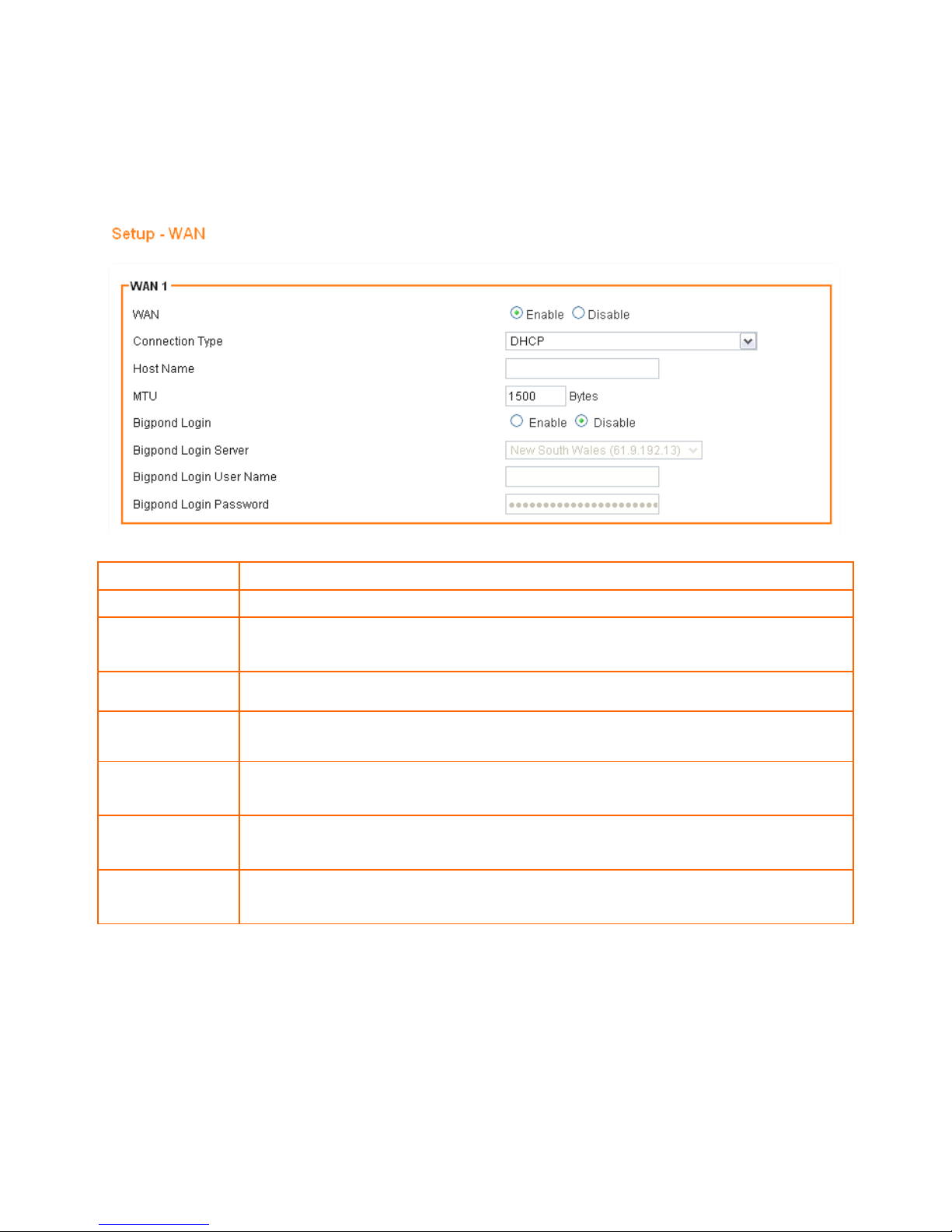
The IP address is automatically assigned to you by your ISP. You will see the following screen when you choose
DHCP.
WAN
Select Enable/Disable to enable/disable WAN
Connection Type
DHCP
Host Name
Some ISP and DHCP servers ask for the Host Name of the DHCP client before
assigning an IP address. In this case, please key in your Host Name.
MTU
Maximum Transmission Unit
Bigpond Login
If you are using “Bigpond” system, please enable this item
Bigpond Login
Server
Please choose the Bigpond server.
Bigpond Login
User Name
Please enter your User Name provided by Bigpond
Bigpond Login
Password
Please enter your Password provided by Bigpond
Page 23
19
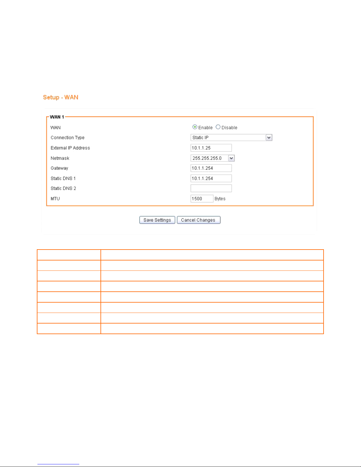
5.1.2 Static (Fixed IP address assignment)
The IP address, subnet mask, gateway, and DNS server are provided by your ISP.
Please enter the information accordingly.
WAN
Select Enable / Disable to enable/disable WAN.
Connection Type
Static IP
External IP Address
The external IP addresses offered by the ISP.
Netmask
The Netmask is offered by the ISP.
Gateway
The gateway offered by the ISP.
Static DNS 1
The static DNS 1 offered by the ISP.
Static DNS 2
The static DNS 2 offered by the ISP.
MTU
Maximum Transmission Unit
Page 24
20
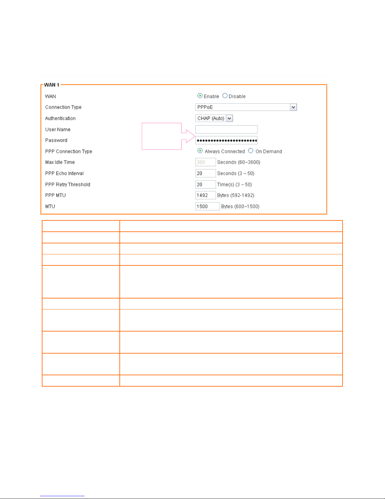
5.1.3 PPPoE (connected by username/password)
If your ISP provides the username and password, please enter the information accordingly.
WAN
Select Enable/Disable to enable/disable WAN
Connection Type
PPPoE
User Name
The user name offered by the ISP.
Password
The password offered by the ISP.
On Demand:
Max Idle Time
PPPoE On Demand will only be activated when there is traffic. When there is
no traffic within max. idle time (default: 300 seconds), PPPoE will be
disconnected.
Keep Alive
PPPoE Keep Alive will maintain the PPPoE dial up connection.
PPPoE Echo Interval
PPPoE echo will ensure whether the link is still up or not (default interval 20
seconds)
PPPoE Retry Threshold
When PPPoE echo retry exceeds PPPoE Retry Threshold (default 20 times),
the dial up connection would be recognized as down.
PPPoE MTU
PPPoE maximum transmission unit: up to 1492 bytes (PPPoE’s header is 8
bytes)(This value should be less than MTU value at least 8 bytes ).
MTU
Physical Device Maximum Transmission Unit
Provided by
your ISP
Page 25
21
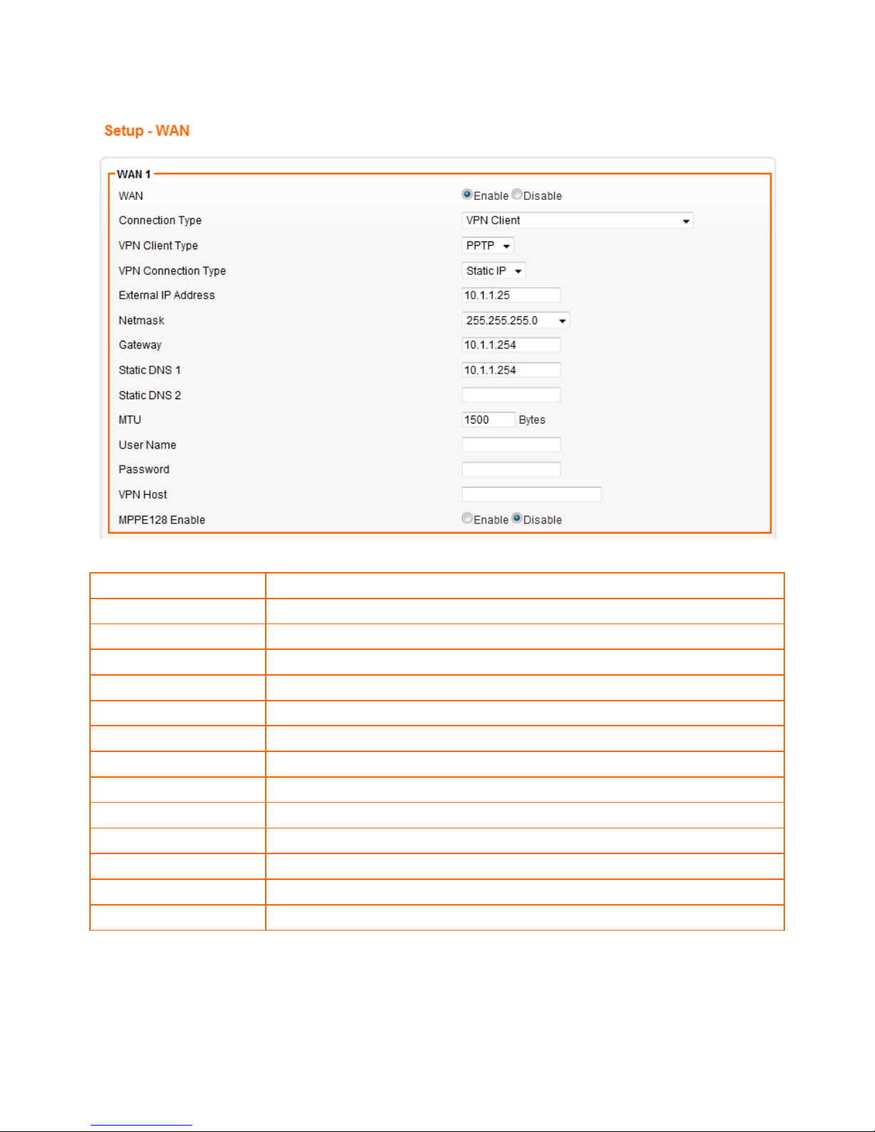
5.1.4 VPN Client
WAN
Select Enable / Disable to enable/disable WAN.
Connection Type
VPN Client
VPN Client Type
PPTP or L2TP can be chosen in the pull-down menu
VPN Connection Type
Static IP or DHCP can be chosen in the pull-down menu
External IP Address
The external IP addresses offered by the ISP.
Netmask
The Netmask offered by the ISP.
Gateway
The gateway offered by the ISP.
Static DNS 1
The static DNS 1 offered by the ISP.
Static DNS 2
The static DNS 2 offered by the ISP.
MTU
Physical Device Maximum Transmission Unit
User Name
The user name offered by the ISP (keep it empty if your ISP doesn’t need it).
Password
The password offered by the ISP (keep it empty if your ISP doesn’t need it).
VPN Host
Host Name/IP of the VPN server.
MPPE128 Enable
Enable/disable the MPPE128 encryption.
Page 26
22
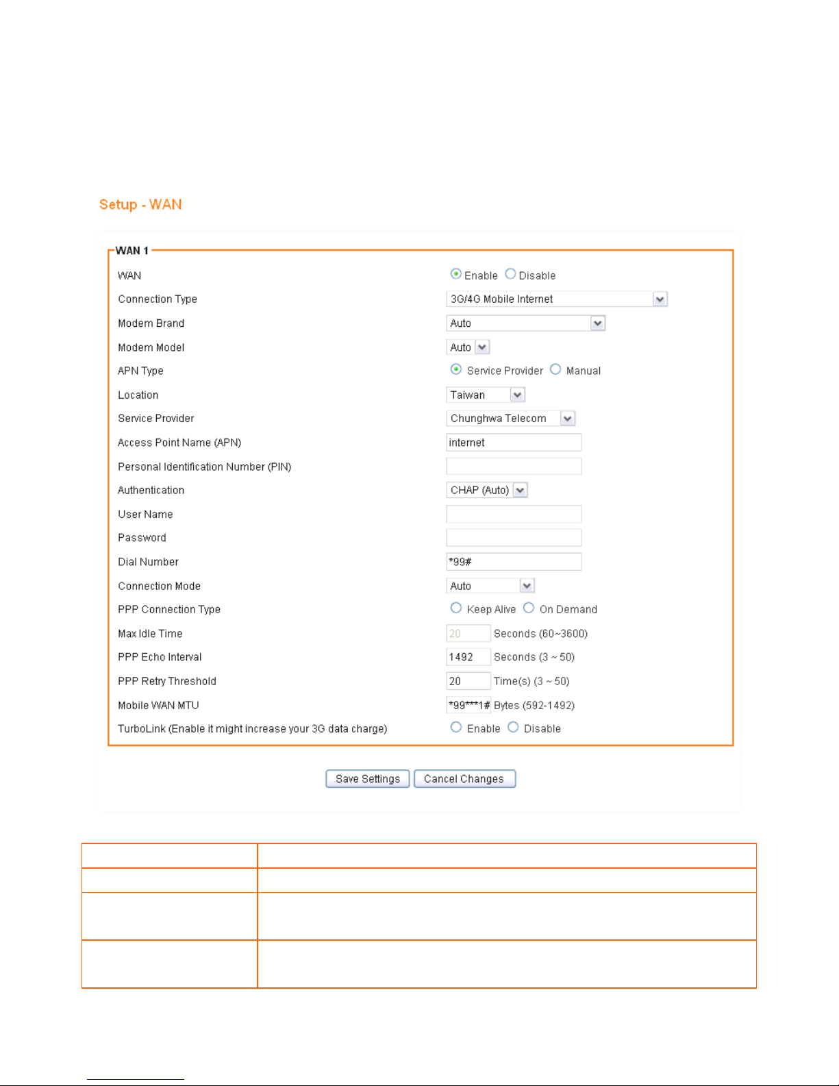
5.1.5 Mobile WAN (connected by information related to what your ISP needs)
Please enter the APN, PIN code, user name, and password provided by your ISP. (Please note that some
information might not be needed.)
WAN
Select Enable/Disable to enable/disable WAN
Connection Type
Mobile WAN
Modem Brand
Choose the modem brand you use. You can keep it as Auto for automatic
detection.
Modem Model
Choose the modem model you use. You can keep it as Auto for automatic
detection.
Page 27

23
APN Type
Choose By Service Provider for specifying the ISP you use, or otherwise choose
Custom to assign desired APN.
Location
Choose your location.
Service Provider
Choose your service provider and the Access Point Name (APN) will be
automatically assigned.
Access Point Name (APN)
Enter APN string offered by the ISP if you select Custom for APN Type (keep it
empty if your ISP doesn’t need it).
Personal Identification
Number (PIN)
Enter PIN code offered by the ISP (keep it empty if your ISP doesn’t need it).
User Name
The user name offered by the ISP (keep it empty if your ISP doesn’t need it).
Password
The password offered by the ISP (keep it empty if your ISP doesn’t need it).
Dial Number
Enter Dial Number offered by the ISP (default *99***1#).
On Demand:
Max Idle Time
PPPoE On Demand will only be activated when there is traffic. When there is
no traffic within max. idle time (default: 300 seconds), PPPoE will be
disconnected.
Keep Alive
PPPoE Keep Alive will maintain the PPPoE dial up connection.
PPPoE Echo Interval
PPPoE echo will ensure whether the link is still up or not (default interval 20
seconds)
PPPoE Retry Threshold
When PPPoE echo retry exceeds PPPoE Retry Threshold (default 20 times), the
dial up connection would be recognized as down.
PPPoE MTU
PPPoE maximum transmission unit: up to 1492 bytes (PPPoE’s header is 8 bytes).
Page 28
24
5.1.6 BlackBerry
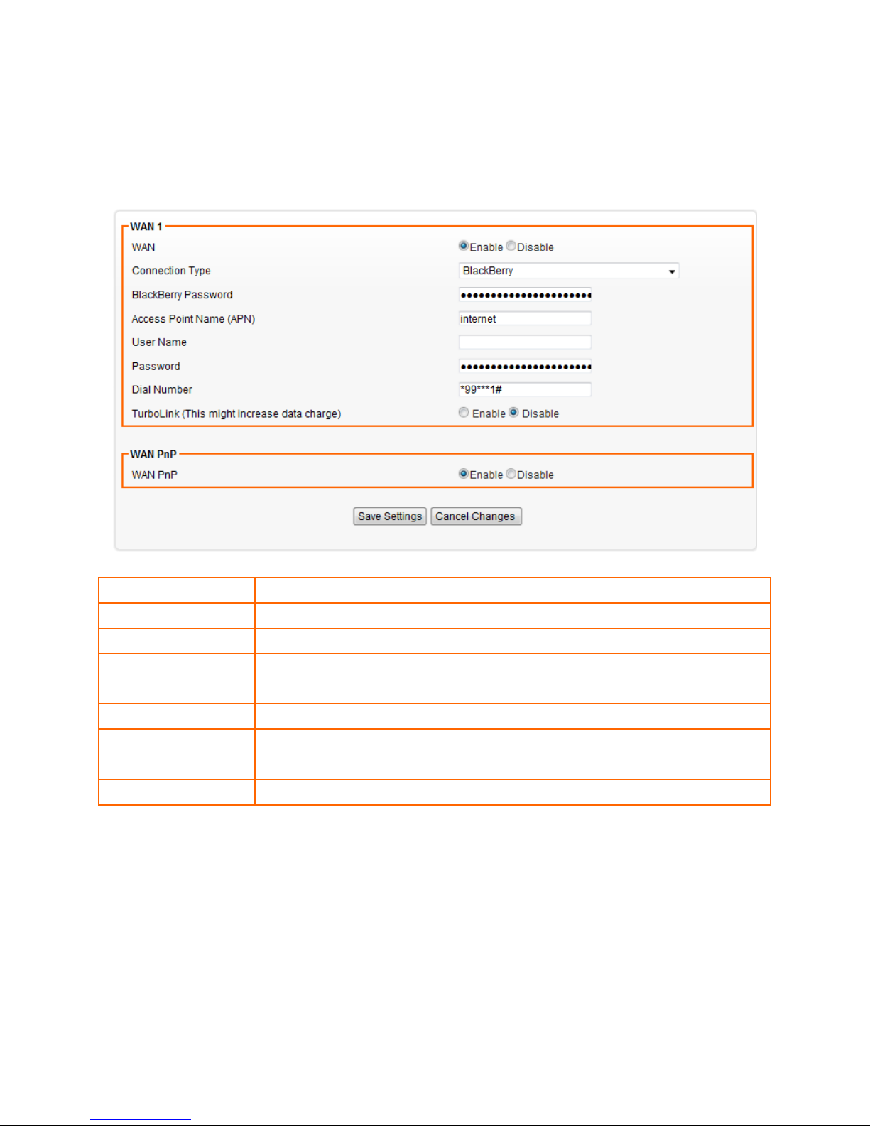
If you want to share your 3G/3.5G network via your BlackBerry, you have to choose this WAN connection type in
the AXIMCom Mobile Router. **Make sure your provider has enabled Data Tethering to your plan.
WAN
Select Enable/Disable to enable/disable WAN
Connection Type
BlackBerry
BlackBerry Password
Enter the password set in the BlackBerry phone.
Access Point Name
(APN)
Enter APN string offered by the ISP if you select Custom for APN Type (keep it
empty if your ISP doesn’t need it).
User Name
Enter your username
Password
Enter your password
Dial Number
Enter Dial Number offered by the ISP (default *99***1#)
TurboLink
Enable “TurboLink” to improve the connection speed and stability.
Page 29
25
5.1.7 Windows Mobile / Google Android Phones
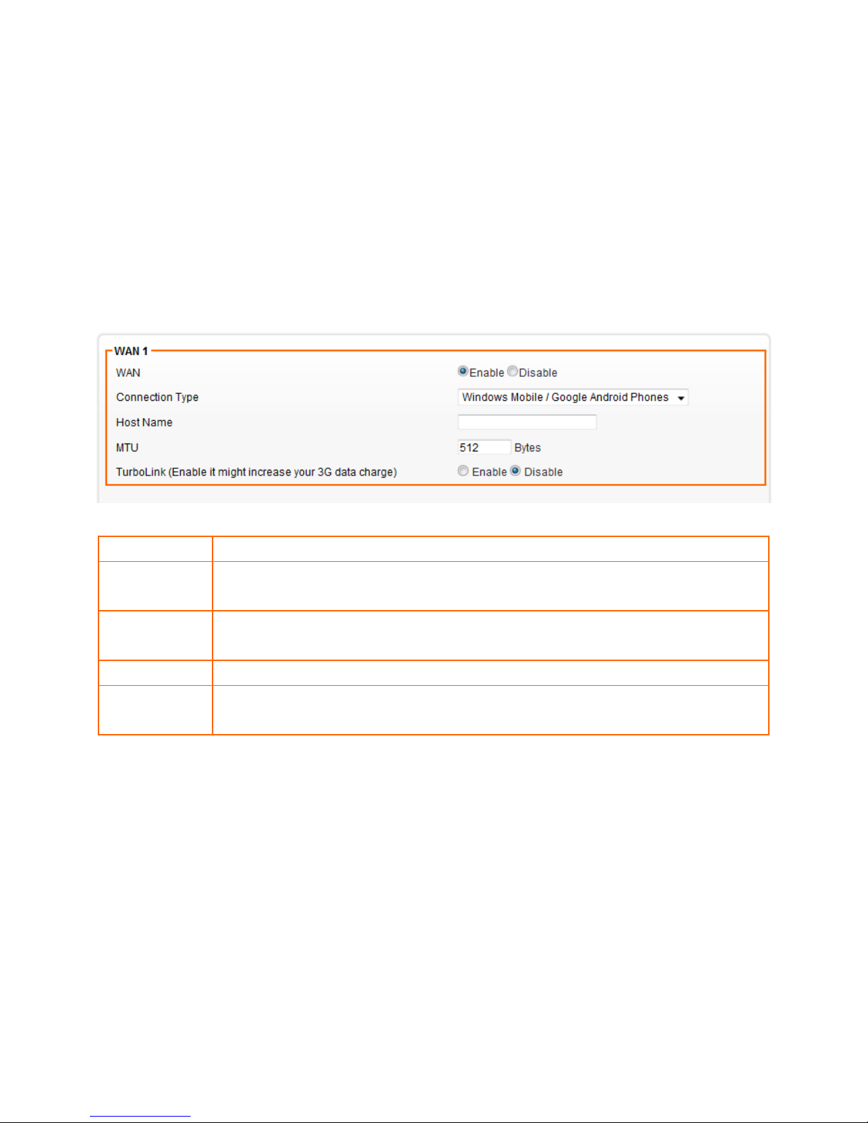
If you want to share your 3G/3.5G network via your Windows Mobile phone, Google Android Phones, you have
to choose this WAN connection type in the AXIMCom Mobile Router.
After connecting your phone and AXIMCom Mobile Router with USB, you need to enable “Internet Sharing” or
“Mobile Network Sharing” function in your Windows Mobile phone, Google Android Phones or iPhone.
**Make sure your provider has enabled Data Tethering to your plan
WAN
Select Enable/Disable to enable/disable WAN
Connection
Type
Windows Mobile / Google Android Phones
Host Name
Some ISP and DHCP servers ask for the Host Name of the DHCP client before
assigning an IP address. In this case, please key in your Host Name.
MTU
Maximum transmission unit
TurboLink
Enable “TurboLink” to improve the connection speed and stability. (Please note that
TurboLink function might increase your 3G data charge)
Page 30
26
5.1.8 HSPA+ Super Speed
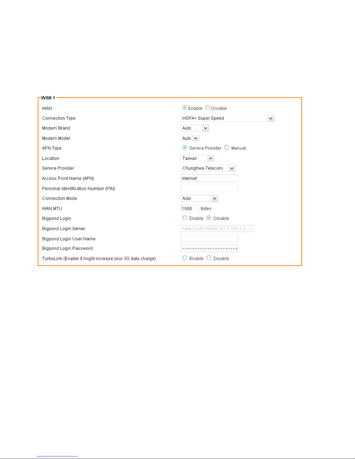
If you using HSPA+ super speed modem, please choose this WAN connection type. Please enter the APN, PIN
code, user name, and password provided by your ISP. (Please note that some information might not be
needed.)
Page 31

27
WAN
Select Enable/Disable to enable/disable WAN
Connection Type
HSPA+ Super Speed
Modem Brand
Choose the modem brand you use. You can keep it as Auto for
automatic detection.
Modem Model
Choose the modem model you use. You can keep it as Auto for
automatic detection.
APN Type
Choose By Service Provider for specifying the ISP you use, or otherwise
choose Custom to assign desired APN.
Location
Choose your location. If not available in the list, please choose [custom]
and enter setting values(APN, PIN) manually
Service Provider
Choose your service provider and the Access Point Name (APN) will be
automatically assigned.
Access Point Name (APN)
Choose By Service Provider for specifying the ISP you use, or otherwise
choose Custom to assign desired APN.
Personal Identification
Number (PIN)
Please enter PIN code
Connection Mode
Choose your connection mode, Please choose AUTO mode.
WAN MTU
Maximum transmission unit
Bigpond Login
If you are using “Bigpond” system, please enable this item
Bigpond Login Server
Please choose the Bigpond server.
Bigpond Login User Name
Please enter your User Name provided by Bigpond
Bigpond Login Password
Please enter your Password provided by Bigpond
TurboLink
Enable “TurboLink” to improve the connection speed and stability.
(Please note that TurboLink function might increase your 3G data charge)
Page 32
28
5.1.9 Apple iPhone
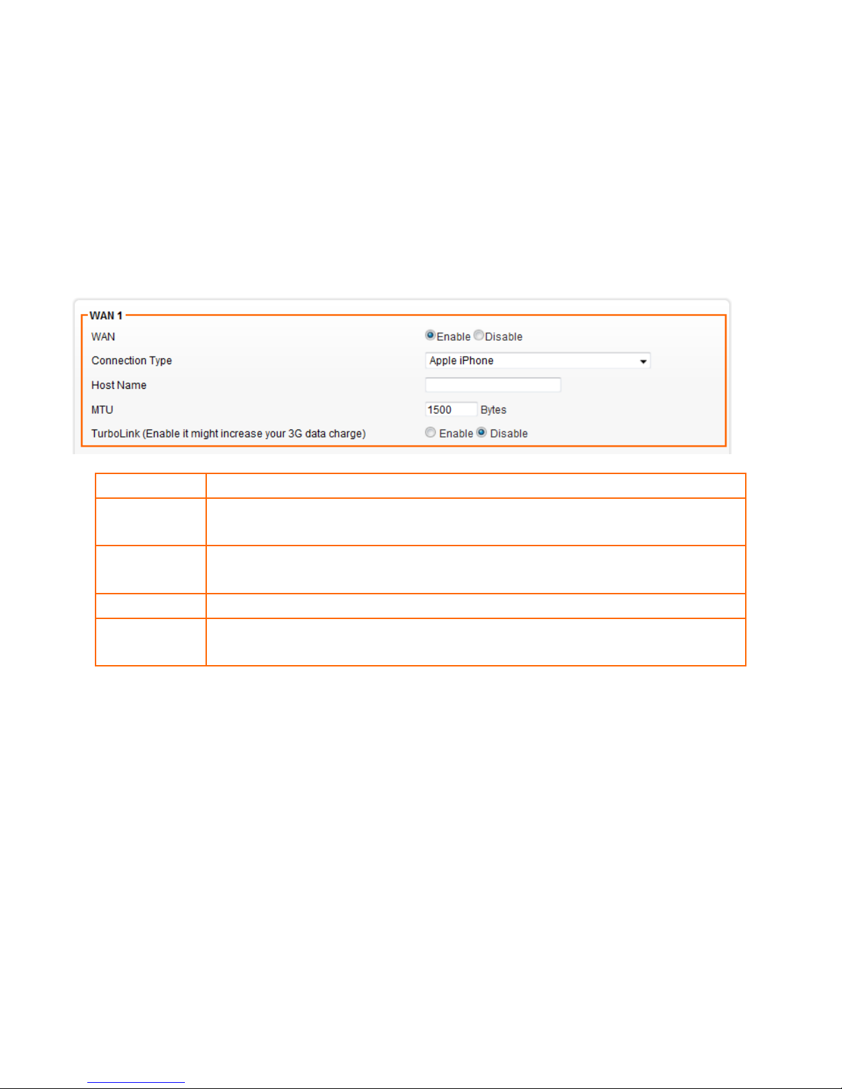
If you want to share your 3G/3.5G network via your iPhone, you have to choose this WAN connection type in the
AXIMCom Mobile Router.
After connecting your phone and AXIMCom Mobile Router with USB, you need to enable “Internet tethering”
function in your iPhone.
**Make sure your provider has enabled Data Tethering to your plan
WAN
Select Enable/Disable to enable/disable WAN
Connection
Type
Apple iPhone
Host Name
Some ISP and DHCP servers ask for the Host Name of the DHCP client before
assigning an IP address. In this case, please key in your Host Name.
MTU
Maximum transmission unit
TurboLink
Enable “TurboLink” to improve the connection speed and stability. (Please note that
TurboLink function might increase your 3G data charge)
Page 33
29
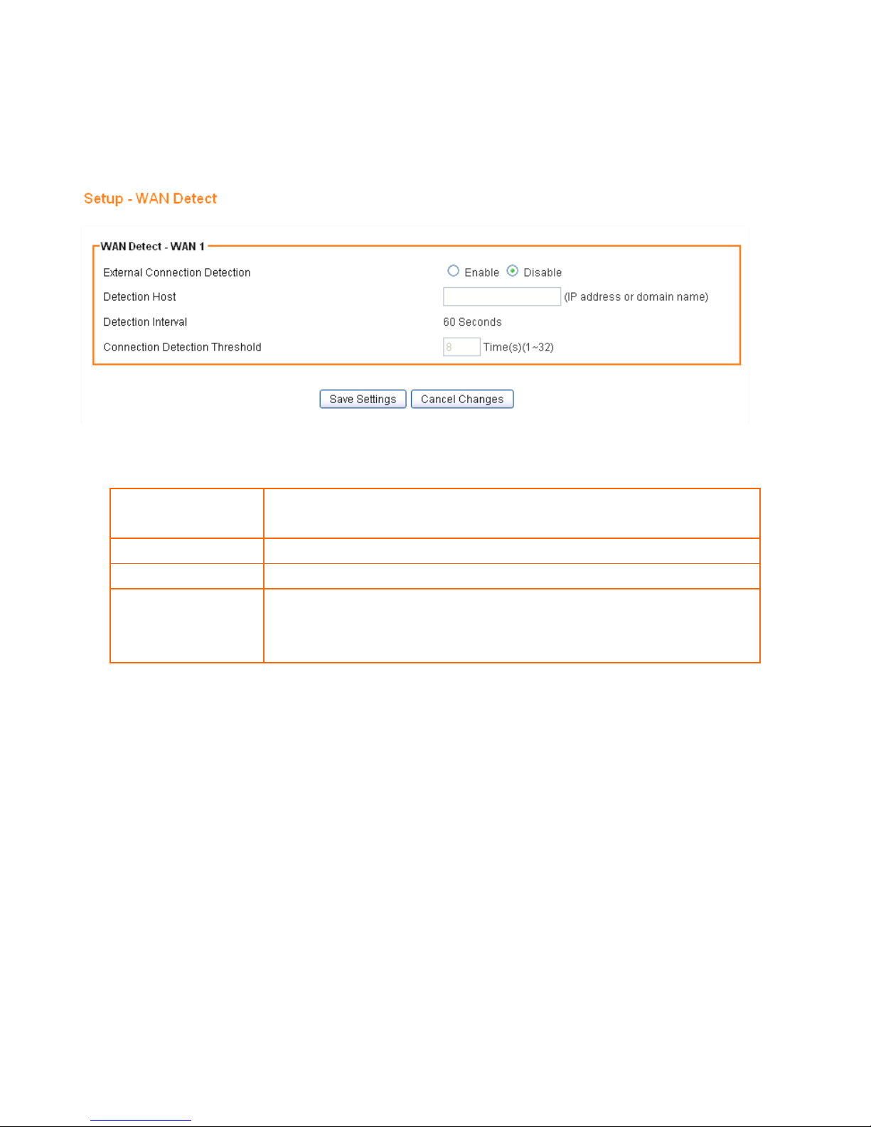
5.2 WAN DETECT
1. Click on [Setup] – [WAN Detect] tab. You will see the following screen.
2. Configure the basic settings of WAN Detect following the instructions below.
External Connection
Detection
Choose Enable/Disable to enable/disable connection detection.
Detection Host
Enter the IP address or domain name of the host to be detected.
Detection Interval
Detection Interval is 60 seconds
Connection
Detection Threshold
The system will generate a PING packet to detect whether the connection
is still connected. If the Host is not response for this threshold value, the
system is considered to be WAN lost.
Page 34
30
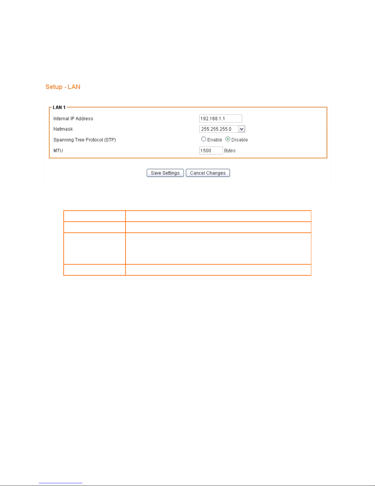
5.3 LAN SETUP
1. Click on [Setup] – [LAN] tab. You will see the following screen.
2. Configure your LAN following the instructions listed below.
Internal IP Address
Please key in Internal IP Address
Netmask
Select Netmask from the selection list.
Spanning Tree
Protocol (STP)
Click Enable to avoid cyclic topology caused by incorrect
connection of your internal network. (A cyclic topology will
cause network breakdown.)
MTU
Maximum transmission unit: up to 1500 bytes.
Page 35
31
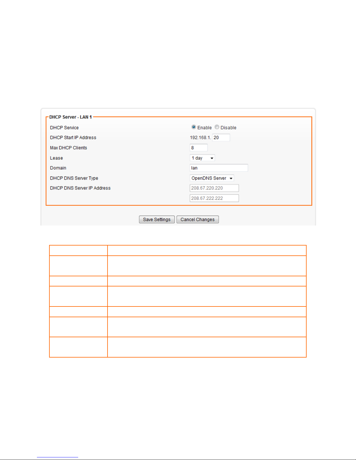
5.4 DHCP SERVER SETUP
AXIMCom Mobile Router provides DHCP server service in order to offer IP addresses to the computers within a
LAN.
1. Click on [Setup] – [DHCP] tab. You will see the following screen.
2. Configure your LAN following the instructions listed below.
DHCP Server
Select Enable/Disable to enable/disable DHCP Server.
DHCP Start IP
Address
The DHCP starting IP addresses offered by the DHCP Server.
Max DHCP Clients
The maximum number of the IP addresses supported by the DHCP server
Lease
Please choose lease time from the selection list. You can choose 1 Hour,
3 Hours, 6 Hours, 1 Day, 3 Days, or 7 Days.
Domain
Please enter the domain name.
DHCP DNS Server
Type
Select the predefined DNS server or choose “custom” to specify a DNS
server by yourself.
DHCP DNS Server IP
Address
Enter the specified DNS Server IP.
Page 36
32
5.5 DDNS SETUP
DDNS (Dynamic Domain Name Service) allows an “internet domain name” to be assigned to a
computer/router which has a dynamic IP address. This makes it possible for other internet devices to connect to
the computer/router without needing to trace the changing IP addresses themselves. To enable DDNS, you will
first need to sign up for DDNS services from DynDNS.org, TZO.com or ZoneEdit.com.
DDNS is useful when combined with the virtual server feature. It allows other internet users to connect to your
virtual server by using a domain name, rather than an IP address. The DDNS service helps users to locate the
right IP address by the domain name.
For example, you wish to set up a personal web server. However, you obtain a different IP address from your ISP
every time you connect to the internet. The dynamic IP address you have will cause difficulty for other internet
users to find your web server. In this case, you will need to enable DDNS, so other users can connect to you
through a fixed domain name to disregard the potential varying IP addresses behind the server.
1. Register with one of the DDNS providers (DynDNS.org, TZO.com or ZoneEdit.com) before you
configure DDNS on the AXIMCom Mobile Router.
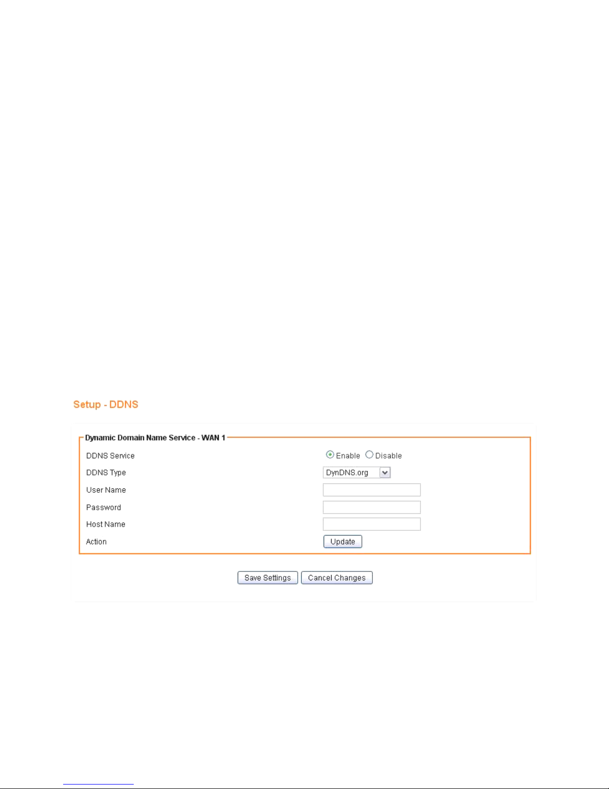
2. Click on [Setup] – [DDNS] tab. You will see the following screen.
Page 37

33
3. Configure your DDNS following the instructions listed below.
DDNS Service
Select Enable to enable DDNS service.
Select Disable to disable DDNS service.
DDNS Type
Select the desired DDNS service provider from the list.
User Name
Enter your username
Password
Enter your password
Host Name
Apply for a domain name, and make sure it is allocated to you
Page 38

34
5.6 MAC ADDRESS CLONE SETUP
Some ISPs only allow a registered MAC address to access to the internet. To bypass the rule, you need to set up
a cloned MAC address for AXIMCom Mobile Router using the pre-registered MAC address.
1. Click on [Setup] – [MAC Address Clone] tab. You will see the following screen.
2. Configure your Internet Connection (WAN) MAC Clone following the instructions below.
Clone WAN MAC
If your ISP only grants access to a fixed MAC address, please select Enable.
If your ISP does not enforce access control, please select Disable.
MAC Address
If the PC you use to configure AXIMCom Mobile Router is the device which
has the right MAC address to access the internet, press Get Current PC MAC
Address button. Or you can type in the MAC Address which has been
granted access by your ISP.
Page 39
35
5.7 TIME SETUP
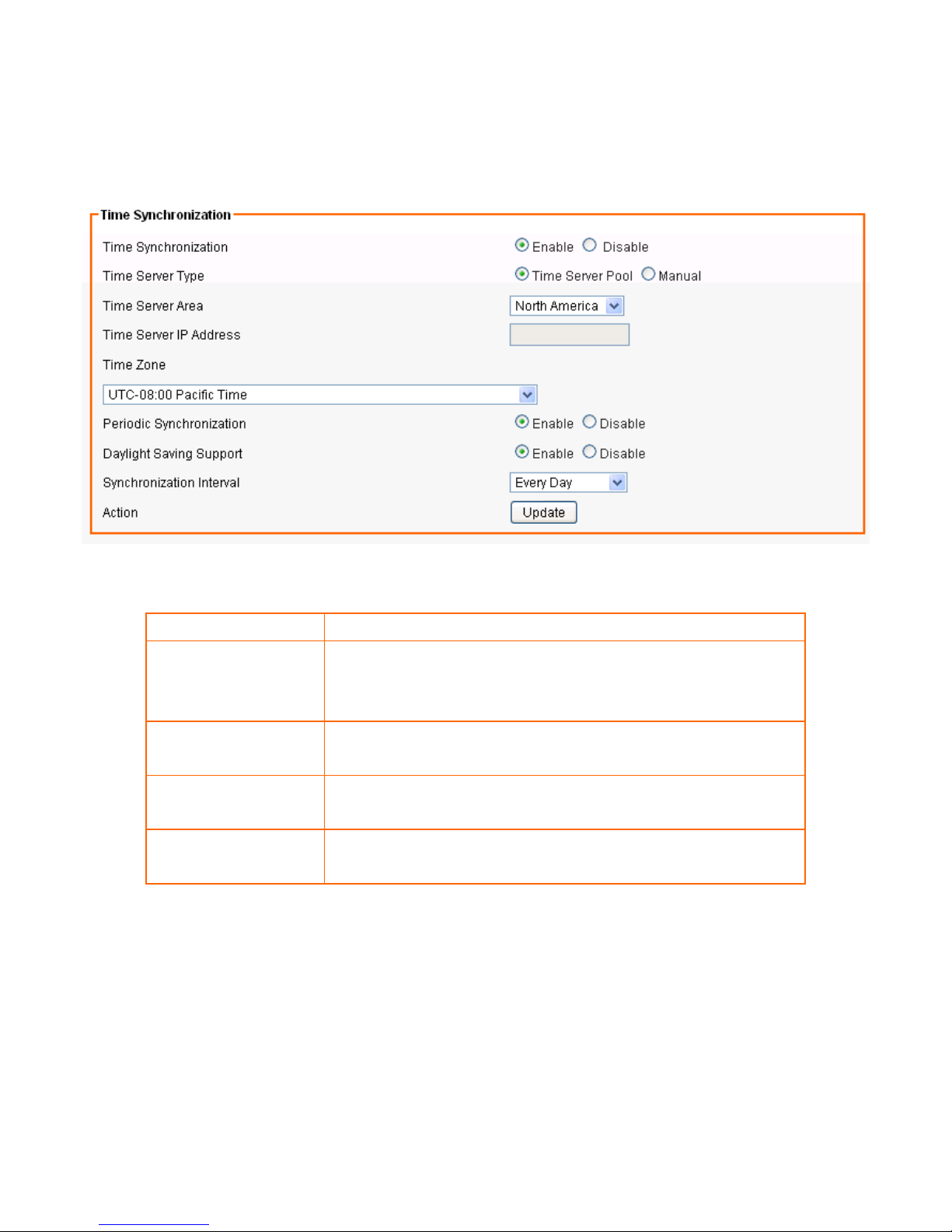
1. Click on [Setup] – [Time] tab. You will see the following screen.
2. Configure [Time] Settings based on the instructions listed below
Time Synchronization
Select Enable/Disable to enable/disable Time Synchronization
Time Server
Select Time Server according to your location. You can choose
from Automatic, Asia, Europe, North America, South America, or
Africa.
Time Zone
Select Time Zone according to your location. (Daylight Saving
Time has been calculated and included in the selection).
Periodic
Synchronization
Select Enable/Disable to enable/disable Periodic Synchronization
Synchronization
interval
Select from Every Hour, Every 6 Hours, Every 12 Hours, Every Day,
and Every Week.
Page 40
36
CHAPTER6 WIRELESS SETTINGS
6.1 BASIC SETUP
Multiple SSIDs allow the ability for separate security mode and key settings to be set by users for both
convenience and increased protection. Users are able to configure their network devices to access the first SSID
with the WPA2 PSK (Pre-Shared Key) and secret key, whilst share the second SSID with WEP and the periodically
changed key for visitors. In addition, users are able to isolate these SSIDs to avoid malicious attacks and prevent
certain access for visitors using the second SSID. This then provides users an extremely convenient approach to
share the wireless access, provide access internet access for visitors, while possessing a strong security
protection system at all times.
6.1.1 Settings
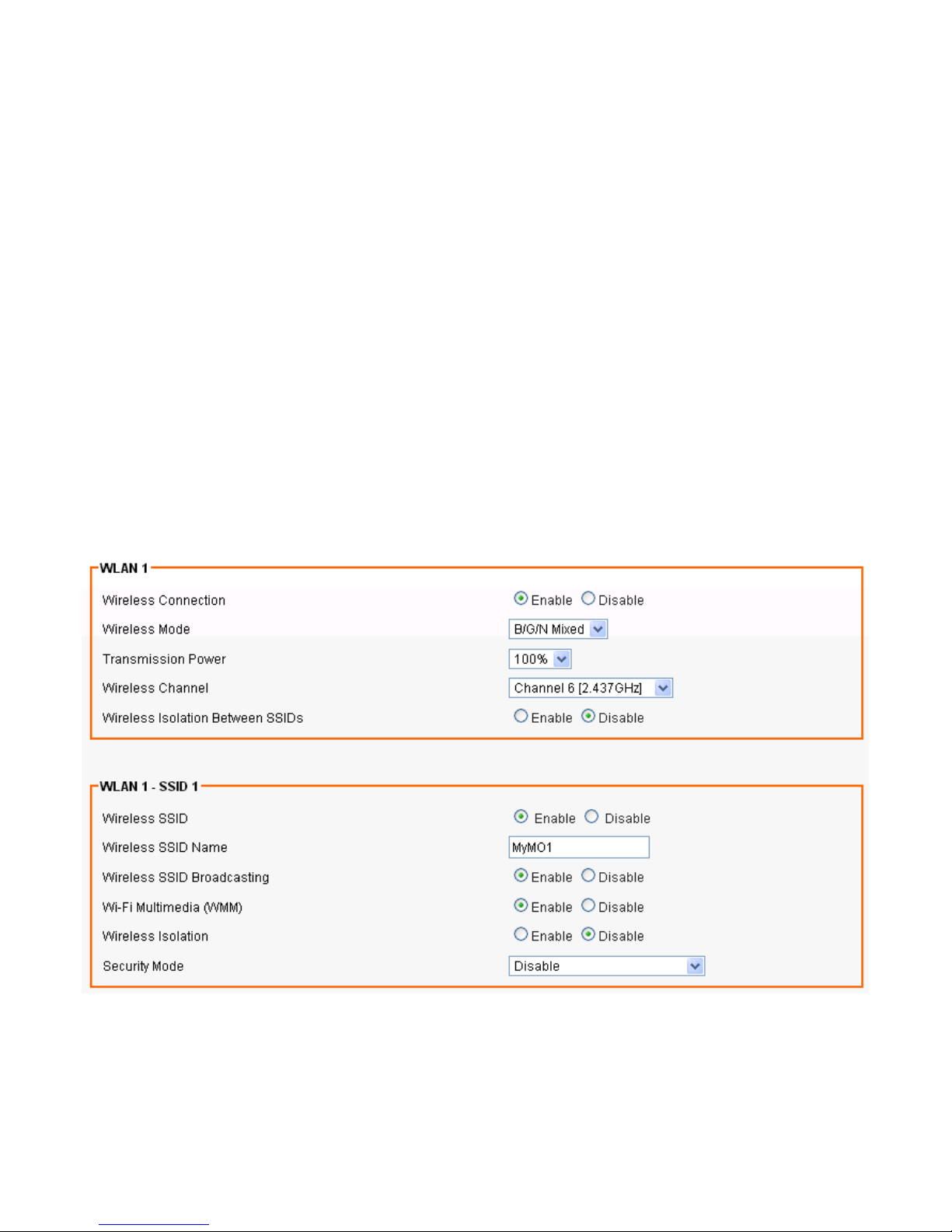
1. Click on [Wireless] – [Basic] tab. You will see the following screen.
Page 41

37
2. Configure wireless settings following the instructions below.
Wireless
Connection
Select Enable if you would like to turn on the wireless signal
Select Disable if you would like to turn off the wireless signal.
Wireless Mode
Select the wireless mode for 802.11b/g/n or mixed use.
Transmission
Power
Select the transmission power class from 10%, 25%, 50%, 75%, and 100%.
Wireless Channel
Select which channel to be located to.
Wireless Isolation
Between SSIDs
Select Enable if you would like to omit the access from one SSID to another.
Select Disable if you would like to allow the access from one SSID to another.
(This Feature is to create a secure mobile Network between users and guests.)
Page 42
38
6.1.2 SSID Settings
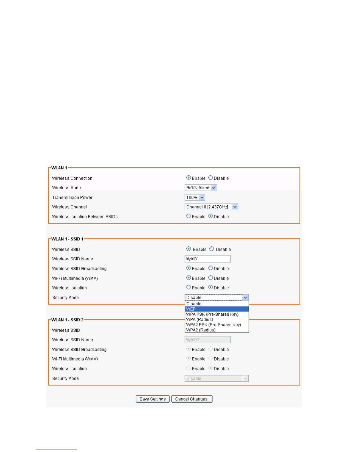
Users are able to configure each SSID with its own attributes. Furthermore, various security modes are available
based on the user’s needs and preference: Disable, WEP, WPA Pre-Shared Key, WPA, WPA2 Pre-Shared Key,
and WPA2. However, it is important to note that all devices under the wireless network must use the same
security mode.
You can configure the security settings of your wireless network to suit your desired preference. Different
methods will grant different levels of security. Using encryption - data packet is encrypted before transmission -
can prevent data packets from being intruded on by un-trusted parties. However, please note that the higher
the security level is, the lower the data throughput becomes.
1. Click on [Wireless] – [Basic] tab. You will see the following screen.
Page 43

39
2. Configure SSID settings following the instructions below.
Wireless SSID
Select Enable if you would like to turn on this SSID.
Select Disable if you would like to turn off this SSID.
WirelessSSID
Name
Enter the wireless station name you would like to have.
Wireless SSID
Broadcasting
AXIMCom Mobile Router broadcasts SSID periodically. Select Enable to turn it on or
Disable to turn it off.
Enabling SSID Broadcasting brings convenience for users to find and connect
AXIMCom Mobile Router.
Disabling SSID broadcasting enhances the security by hiding SSID information.
Wi-Fi Multimedia
(WMM)
Select Enable to prioritize different traffic types based on their characteristics.
For example, VoIP or video traffic will have higher priorities over ordinary traffic.
Wireless
Isolation
Select Enable if you would like to omit the access to other network devices
connecting to this SSID.
Select Disable if you would like to allow the access to other network devices
connecting to this SSID.
Page 44
40
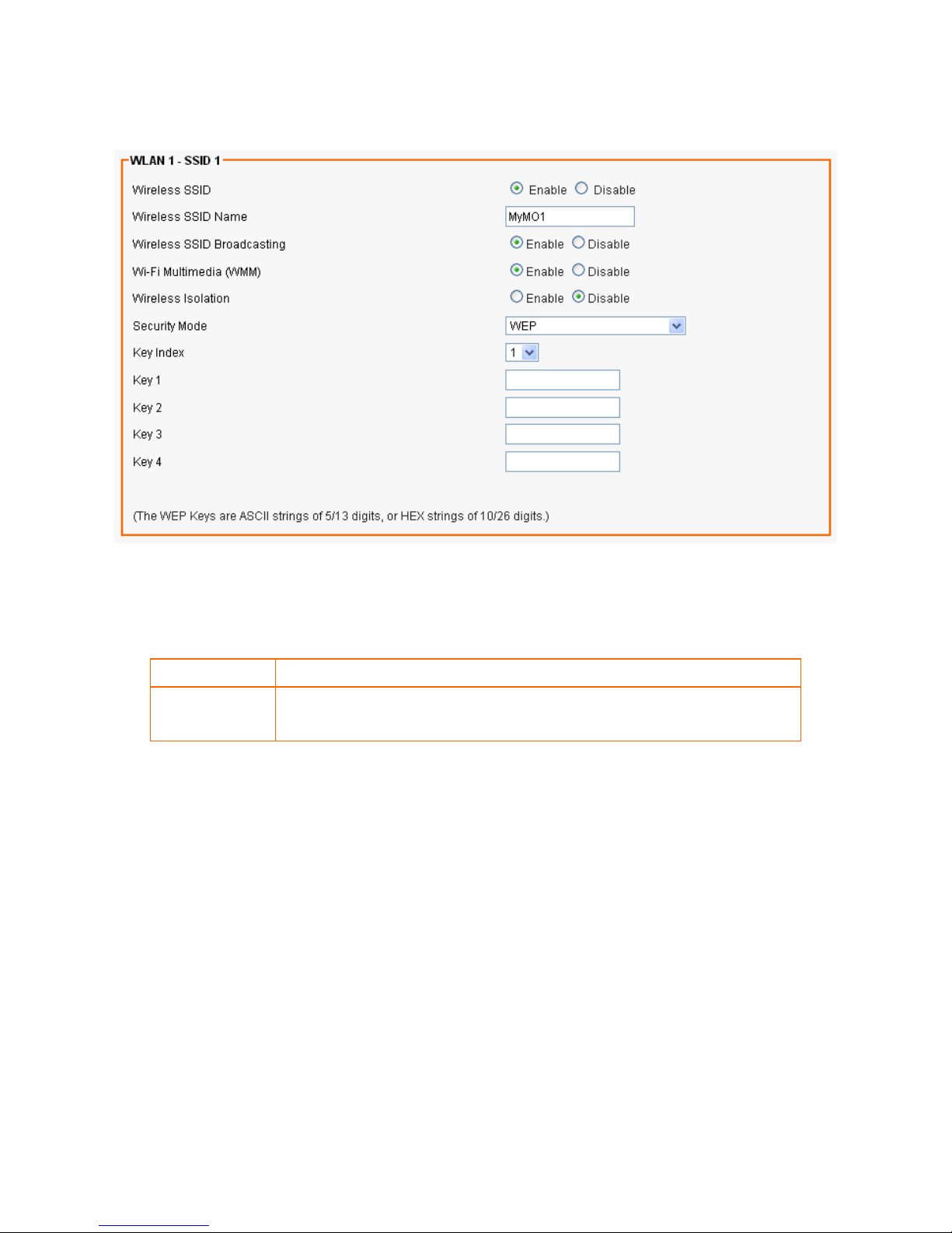
6.1.3 WEP
If WEP is selected, WEP index and keys should be set manually.
WEP Key Index
WEP Key Index indicates which WEP key is used for data encryption.
WEP Key (1~4)
64-bit WEP: type 10 hexadecimal digits or 5 ASCII characters
128-bit WEP: type 26 hexadecimal digits or 13 ASCII characters.
Page 45
41
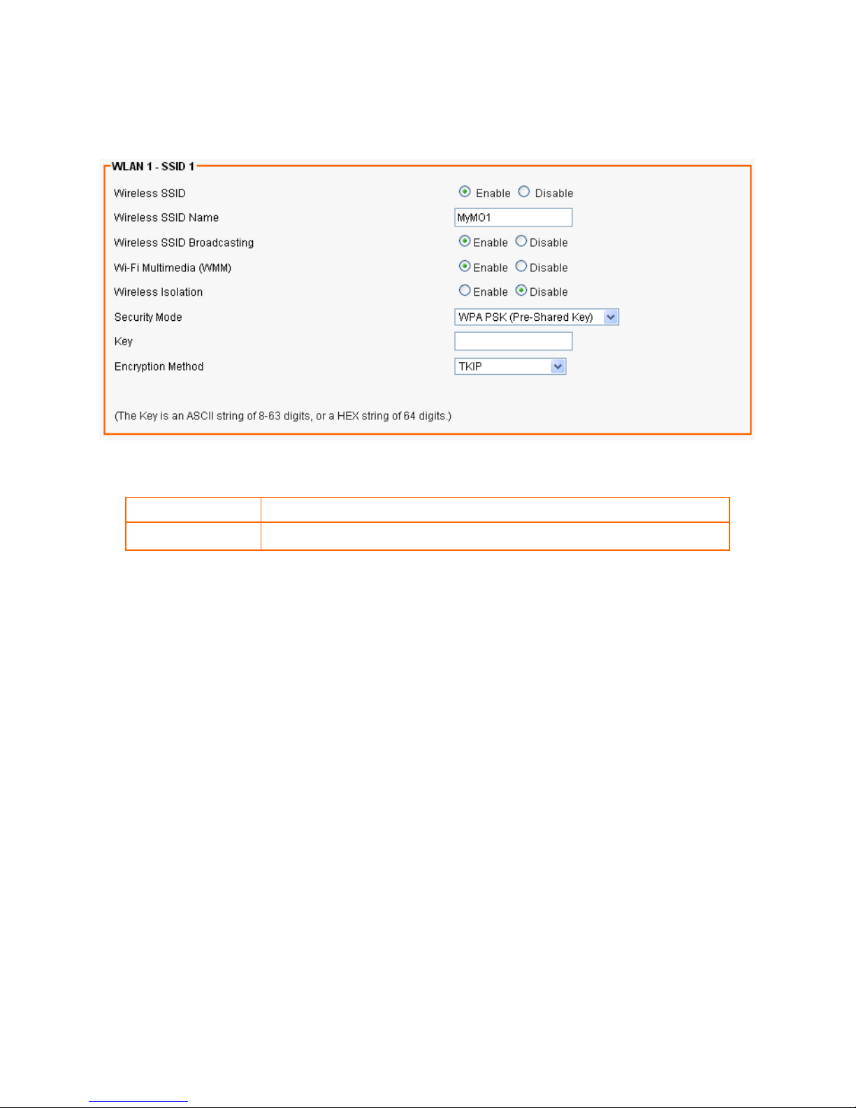
6.1.4 WPA Pre-shared Key / WPA2 Pre-shared Key
If WPA Pre-shared Key or WPA2 Pre-shared Key is selected, Pre-shared Key is supposed to be set.
Pre-shared Key
Pre-shared Key serves as the credential for the packet encryption.
Encryption Mode
TKIP/AES are supported.
Page 46
42
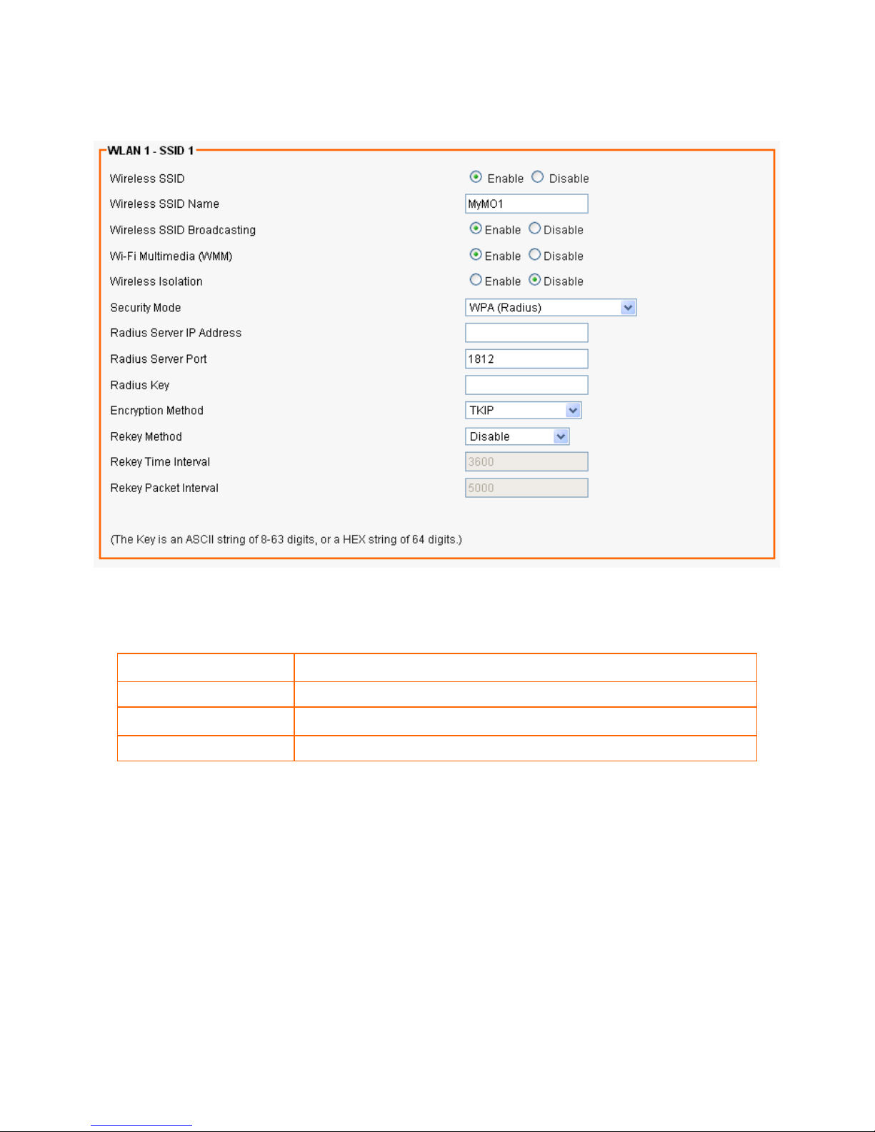
6.1.5 WPA / WPA2(RADIUS)
If WPA or WPA2 is selected, the radius server information should be set accordingly.
Radius Server IP Address
Enter the RADIUS server’s IP address.
Radius Server Port
Enter the RADIUS server’s port number. The default port is 1812.
Radius Key
Enter the RADIUS server’s IP Address.
Encryption Mode
Select TKIP or AES for the packet encryption.
Page 47
43
6.2 ADVANCED SETUP
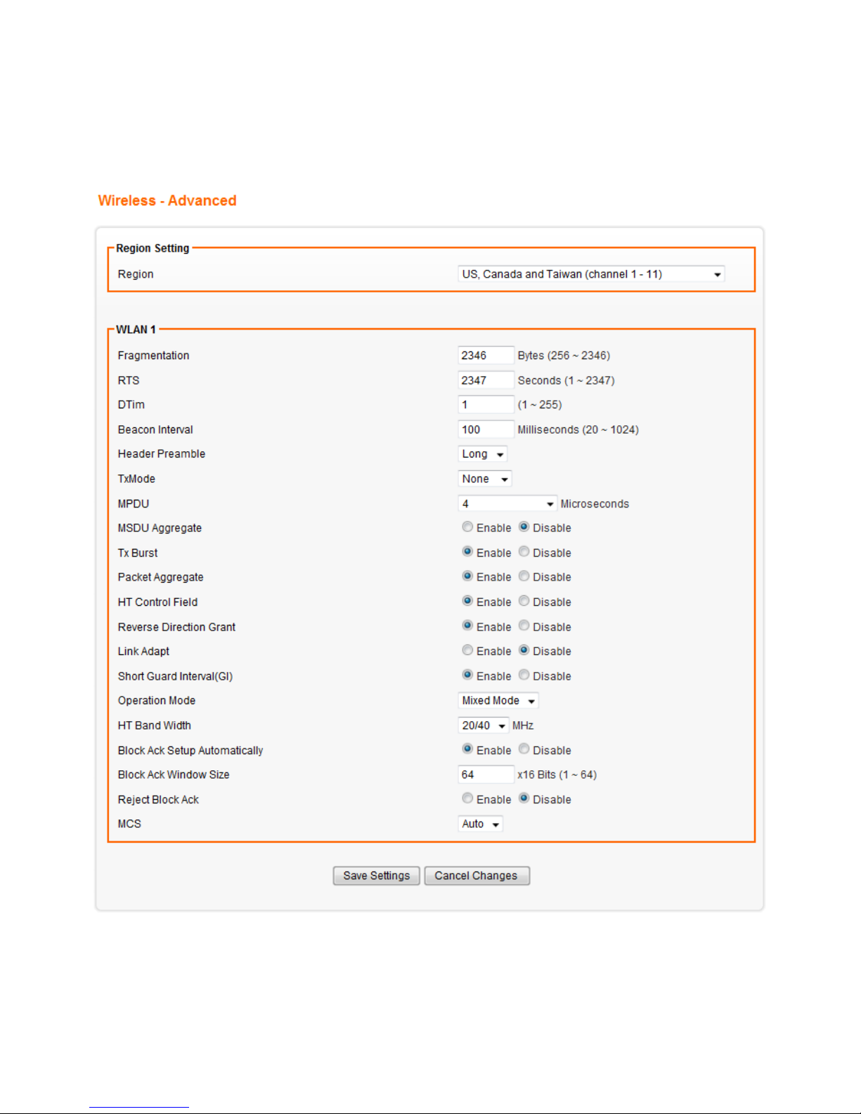
1. Click on [Wireless] – [Advanced] tab. You will see the following screen.
Page 48

44
2. Configure wireless advanced settings following the instructions below.
Region
Choose the region you are currently located in.
Fragmentation
Enter the fragmentation bytes. The default value is 2346 bytes.
RTS
Enter the RTS seconds. The default value is 2347 seconds.
DTim
Enter the DTim seconds. The default value is 1.
Beacon Interval
Enter the interval to send a beacon. The default value is 100 milliseconds.
Header Preamble
Choose Long or Short header preamble.
TxMode
Choose different transmission mode.
MPDU
MPDU data length. The transmission rate is increase when you choose a
larger number, but usually the max value will be 4 in the wireless card
MSDU Aggregate
A kind of packet aggregation method, it can improve the transmission
efficiency. Please make sure you Wireless card has this function supported.
Tx Burst
Some 802.11g wireless cards can support this mode, and the transmission
rate can be increased when this function is enabled.
Packet Aggregate
An aggregation method like A-MSDU, it can improve the transmission
efficiency. Please make sure you Wireless card has this function supported.
HT Control Field
Choose Enable/Disable. It is useful when you need to debug the wireless
network
Reverse Direction Grant
Choose Enable/Disable. The response time can be shorter when this
function is enabled.
Link Adapt
Choose Enable/Disable. The function is used to dynamically change the
modulation and encode mechanism between wireless devices.
ShortGuard Interval(SGI)
Choose Enable/Disable. Short GI can improve some transmission rates, but
with less immunity when interference exist.
Operation Mode
Choose Mixed mode or Greenfield. You may choose Greenfield mode to
increase the transmission rate when you using 802.11n wireless network only.
HT Band Width
Using HT20MHz or HT20/40MHz
Block Ack Setup
Automatically
Choose Enable/Disable. If your Wifi Card supports Block Ack mechanism, it
can improve the data transmission efficiency when this function is enabled.
Block Ack Window Size
Specify a Block Ackwindow size
Reject Block Ack
Choose Enable to reject the request of BA from other Wireless devices
MCS
Select transmission (connection) speed.
Page 49
45
6.3 WDS SETUP
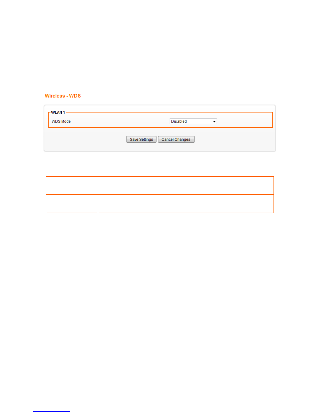
WDS (Wireless Distributed System) enables the wireless bridging amongst several wireless devices. The bridged
devices are identified by the WDS MAC addresses.
1. Click on [Wireless] – [WDS] tab. You will see the following screen.
2. Configure WDS settings following the instructions below.
WDS Mode
Select Enable to enable WDS function.
Select Disable to disable WDS function.
MAC Address [1~4]
Enter the MAC addresses of the other bridged wireless devices.
Maximum of 4 devices are allowed to be bridged together.
*Please make sure of the following settings in order to allow WDS to work effectively:
(1) WDS bridged devices must use the same radio channel.
(2) WDS bridged devices must use the same encryption mode and encryption keys.
Please Note: If one of the above fails, WDS devices cannot communicate with each other.
Page 50
46
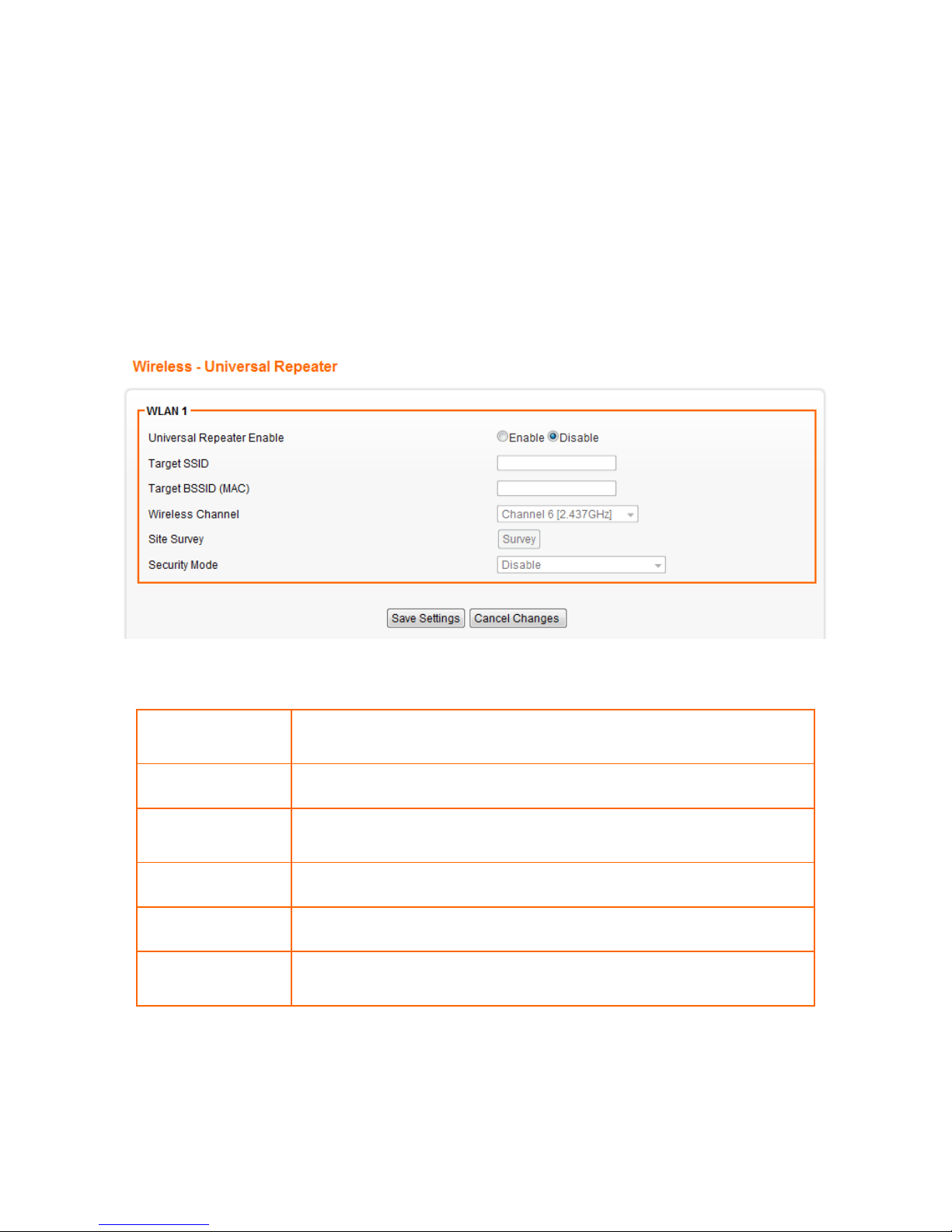
6.4 UNIVERSAL REPEATER SETUP
The Universal Repeater function is similar with WDS in that it is used to essentially enlarge the area of wireless
network coverage. However, unlike WDS, Universal Repeater offers simplicity in configuration requirements, as
users only need to configure the current AP as a client, and to connect it to the second AP’s SSID (or BSSID).
However, you need to ensure that the two APs are using the same wireless channel and security mode (and key)
for Universal Repeater to work effectively.
1. Click on [Wireless] – [Universal Repeater] tab. You will see the following screen.
2. Configure universal repeater settings following the instructions below.
Universal Repeater
Select Enable to enable Universal Repeater function.
Select Disable to disable Universal Repeater function.
Target SSID
Enter the target SSID to connect to.
Target BSSID (MAC)
Enter the target BSSID to connect to. The BSSID is optional if you setup
the target SSID.
Wireless Channel
Select which channel to be located to.
Site Survey
Click the Tab to use site survey choosing the Target SSID
Security Mode
Choose the security mode the target AP uses, and enter the key if
needed.
Page 51
47
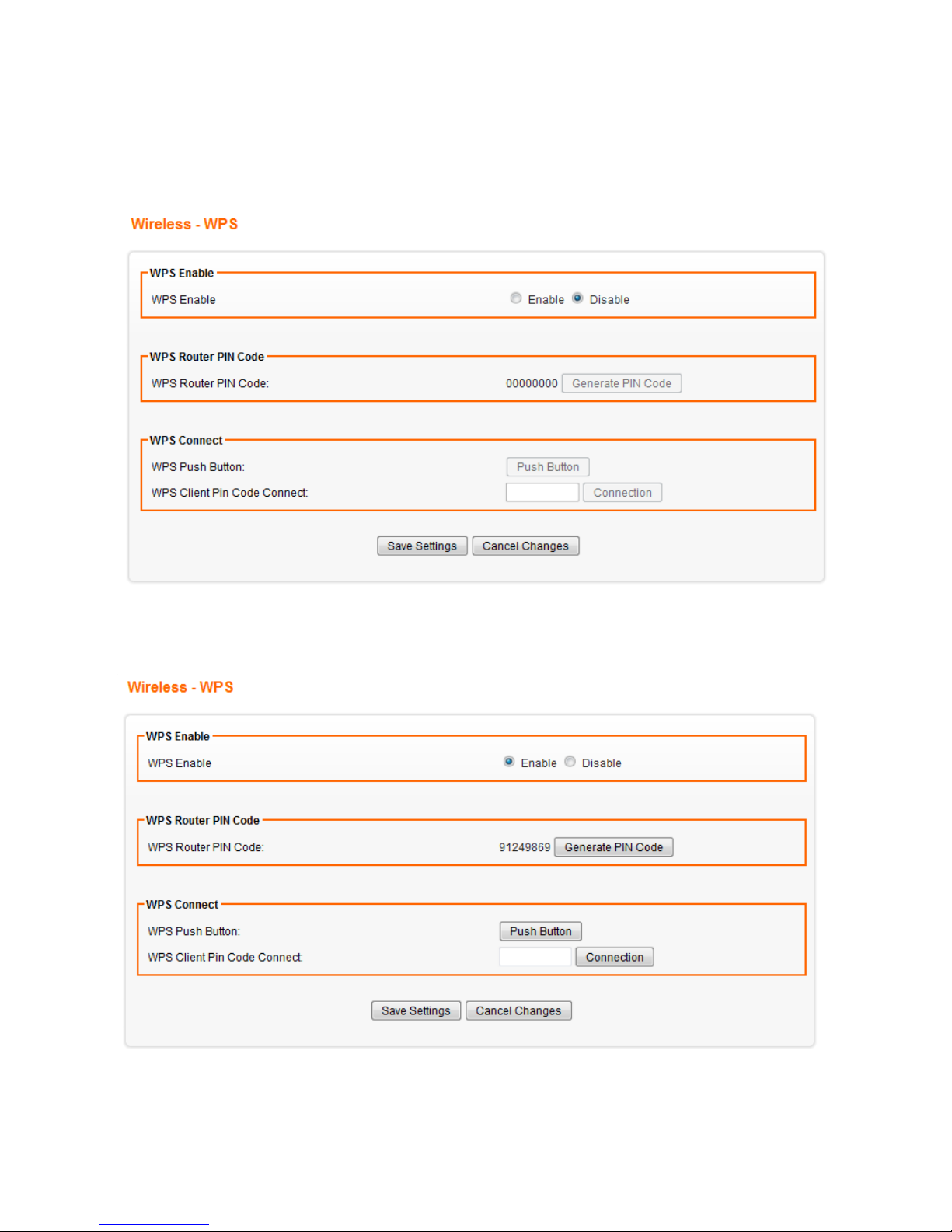
6.5 WPS SETUP
1. Click on [Wireless] – [WPS] tab. You will see the following screen.
2. Click on [Enable] and [Save Settings] tab to saving this setting. You will see the following screen.
Page 52

48
Two approaches of WPS connecting can be used,
(1) Click on [Push Button]then press the WPS button on the client device intended to connect to the router
within 2 minutes. The connection will be established when the [Please wait] screen disappears.
(2) Please enter the WPS PIN code generated from the client device intended to connect to the Router. And
then click on [Connection] tab, the client device will connect to the router automatically.
Page 53
49
CHAPTER7 SECURITY SETTINGS
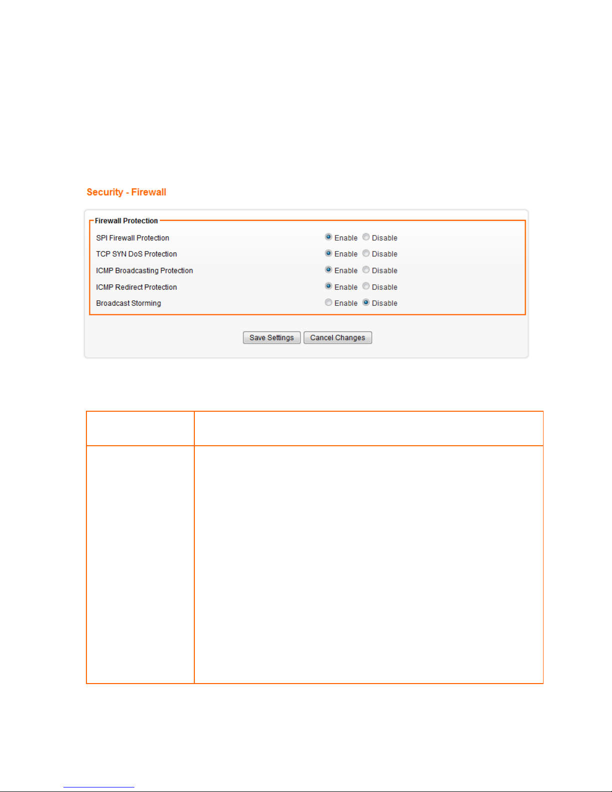
7.1 FIREWALL SETUP
1. Click on [Security] – [Firewall] tab. You will see the following screen.
2. Configure Security Settings following the instructions below.
SPI Firewall Protection
Select Enable to enable SPI Firewall Protection.
Select Disable to disable SPI Firewall Protection.
TCP SYN DoS
Protection
Check to enable TCP SYN DoS Protection.
Uncheck to disable TCP SYN DoS Protection.
TCP SYN DoS attack sends a flood of TCP/SYN packets. Each of these
packets are like a connection request, causing the server to consume
computing resources (e.g. memory, CPU) to reply and to continuously wait
for the incoming packets. Without TCP SYN Dos Protection, the resources in
the server will be easily consumed completely. This will then consequently
result in the malfunction of the server.
AXIMCom Mobile Router is able to detect TCP SYN DoS attacks and limits
the resource consumption by lowering the incoming request rate by
quickly recycling the resource. Therefore, AXIMCom Mobile Router is still
able to serve normal traffic while it is under such an attack.
Page 54

50
ICMP Broadcasting
Protection
Check to enable ICMP Broadcasting Protection.
Uncheck to disable ICMP Broadcasting Protection.
ICMP broadcasting attack is a type of DoS attacks. A flood of ICMP
broadcasting packets is generated and sent to a server (like AXIMCom
Mobile Router). Consequently, this server will suffer from a huge amount of
interruptions and consumption of computing resources.
AXIMCom Mobile Router is able to stop responding to ICMP broadcasting
echo packets in order to avoid a potential ICMP broadcasting DoS attack.
ICMP Redirect
Protection
Check to enable ICMP Redirect Protection.
Uncheck to disable ICMP Redirect Protection.
An ICMP redirect message is a way to change the existing routing path.
Generally, ICMP redirect packets should not be sent, and so when there is
the occurrence that ICMP redirect packets are sent, it is important to note
that it is very likely to be used as a means for a network attack.
Broadcast Storming
Select Enable to enable Broadcast Storming.
Select Disable to disable Broadcast Storming.
Page 55
51
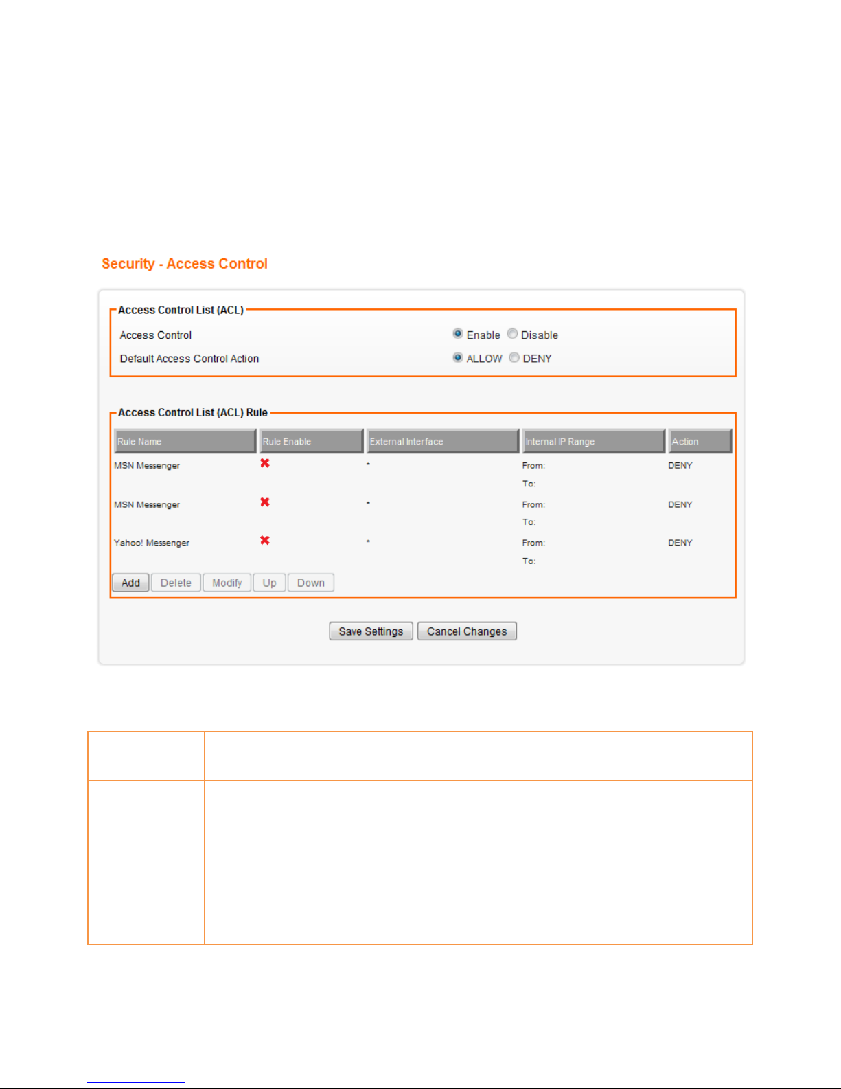
7.2 ACCESS CONTROL LIST (ACL)SETUP
7.2.1 ALC setting
1. Click on [Security] – [Access Control] tab. You will see the following screen.
Please do not change the parameters unless you wish to customize it by yourself.
2. Configure Access Control List (ACL) Settings following the instructions below.
ACL
Select Enable to enable ACL.
Select Disable to disable ACL.
Default ACL
Action
Check Enable to enable a specific MAC Filter rule.
Uncheck Enable to disable a specific MAC Filter rule.
Type the MAC address to permit a device to access the network.
* Enabling MAC filtering blocks all MAC addresses which are not listed in the MAC
Filter Rule. Be aware that adding the MAC address of your managing computer is
required in order to access to AXIMCom Mobile Router.
Page 56
52
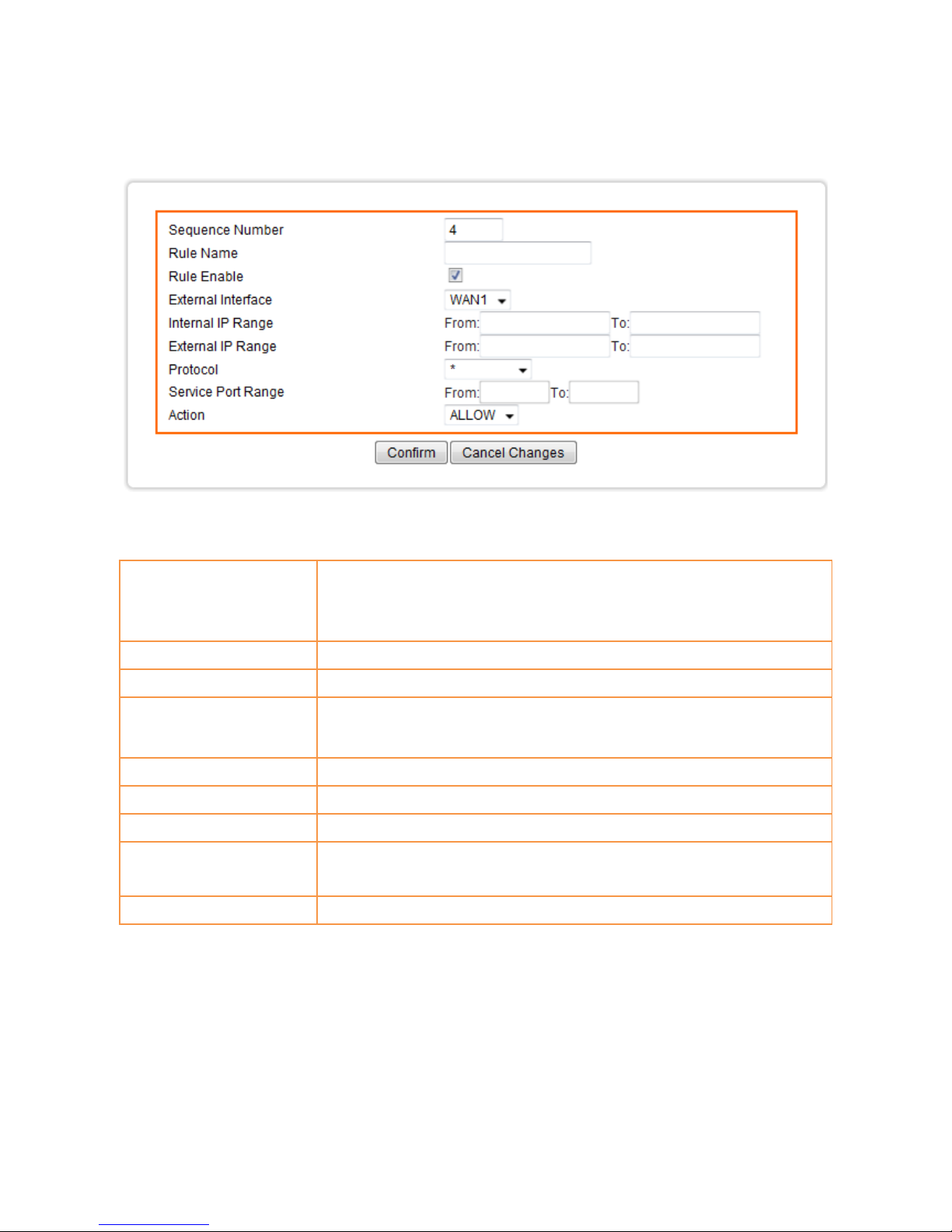
3. Click on [Add] tab. You will see the following screen.
4. Configure [Add Access Control List (ACL)] Settings following the instructions below
Sequence Number
This defines the sequence of the ACL rules. If a packet fits the
conditions set by the ACL rules, the packet will then be sorted
according to the first ACL rule from the top of the list.
Rule Name
Name of the ACL rule.
Rule Enable
Enable/Disable this ACL rule
External Interface
Please select which External Interface (WAN1 or WAN2) you want a
packet to go through, IF the packet fits the condition of this ACL rule.
Internal IP Range
Set up the internal IP range for this ACL rule.
External IP Range
Set up the external IP range for this ACL rule.
Protocol
Set up the protocol (TCP or UDP) for the ACL to be enabled.
Service Port Range
Set up the Service Port Range (e.g., HTTP is TCP/80) for the ACL to be
enabled.
Action
Select ALLOW / DENY。
Page 57

53
5. Example: Filter and block MSN usage.
For example, a company does not wish to allow employees to use MSN. The system administrator can set up an
ACL action: rejecting the traffic going out to External IP Range at 207.46.110.*/24.
Rule Name
MSN Blocking
Rule Enable
Enable
External Interface
* (All complies)
Internal IP Range
Keep it blank (All complies)
External IP Range
207.46.110.1:207.46.110.1.254 (IP address range for MSN server)
Protocol
TCP
Service Port Range
Keep it blank (All complies)
Action
DENY
Page 58
54
7.3 MAC ACCESS CONTROL SETUP
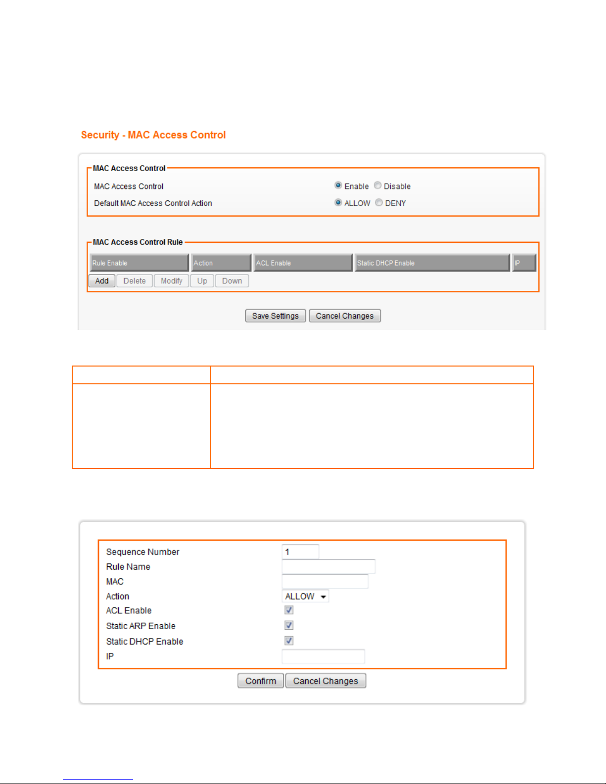
1. Click on [Security] – [MAC Access Control] tab. You will see the following screen.
2. Configure ACL Settings following the instructions below.
MAC Access Control
Choose Enable/Disable to enable/disable MAC access Control
Default MAC Access
Control Action
The default ACL action of the ACL rules. When you add the individual
rules, it can be viewed as exceptions and take effects relating to the
default action.
If the action of the adding rule is the same as the default action, then
this rule will not work.
3. Click on [Add] tab. You will see the following screen.
Page 59

55
Sequence Number
This defines the sequence (priority) of all the MAC ACL actions.
Rule Name
Name of the MAC access rule.
MAC
Set up the MAC Address to which you would like to enable the MAC ACL
action.
Action
Choose ALLOW/DENY to ALLOW/DENY
ACL Enable
Enable/Disable this MAC access rule
Static ARP Enable
Enable/Disable this Static ARP rule
Static DHCP Enable
Enable/Disable this Static DHCP rule
IP
The IP address corresponds to static ARP or static DHCP.
4. Example: Bind IP to a MAC
If users need to bind a IP to a specified MAC (network device), one can follow the settings as below.
Sequence
Number
User1
Rule Name
Enable
MAC
00:33:44:55:66:77
Action
Allow Access
ACL Enable
Enable
Static ARP Enable
Enable
Static DHCP
Enable
Enable
IP
192.168.1.100
Page 60
56
7.4 OpenDNS SETUP
7.4.1 OpenDNS Settings
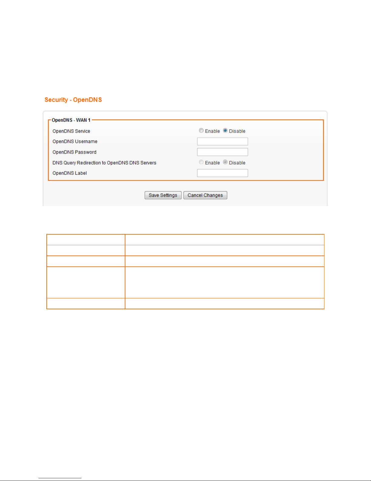
1. Click on [Security] – [OpenDNS] tab. You will see the following screen.
2. ConfigureOpenDNS Settings following the instructions below.
OpenDNS Service
Choose Enable/Disable to enable/disable OpenDNS
OpenDNS Username
Enter OpenDNS user name.
OpenDNS Password
Enter OpenDNS password.
DNS Query Redirection to
OpenDNS DNS Servers
Choose Enable/Disable to enable/disable the data flow redirect to
the OpenDNS Server. Users can get advanced content filtering
function through the setting
OpenDNS Label
Enter the OpenDNS Label
Page 61
57
7.5 WEB FILTERING SETUP
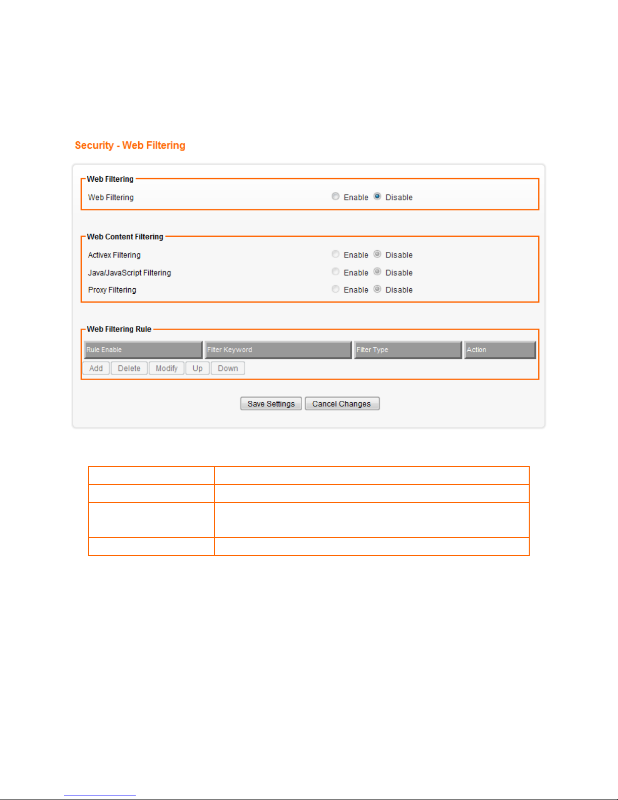
1. Click on [Security] – [Web Filtering] tab. You will see the following screen.
2. Configure Web Filtering Settings following the instructions below.
Web Filtering
Choose Enable/Disable to enable/disable Web Filtering
ActiveX Filtering
Choose Enable/Disable to enable/disable ActiveX Filtering
Java/JavaScript Filtering
Choose Enable/Disable to enable/disable Java/JavaScript
Filtering
Proxy Filtering
Choose Enable/Disable to enable/disable Proxy Filtering
Page 62
58
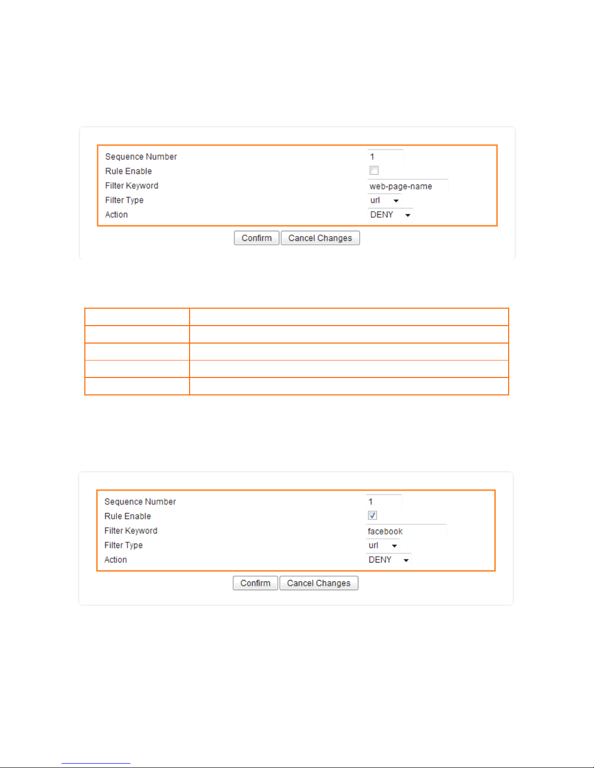
7.5.1 Added Web Filtering Rules
1. Click on [Add] tab. You will see the following screen.
2. Configure Web Filtering Settings following the instructions below
Sequence Number
This defines the sequence (priority) of all the Web Filtering rules.
Rule Enable
Choose Enable/Disable to enable/disable Web Filtering rule
Filter Keyword
Enter the Keyword
Filter Type
Choose URL or Sever
Action
Select ALLOW / DENY。
3. Example: Block a URL with Keyword
If one needs to block a Facebook related web page, they can follow the settings as below
Page 63

59
CHAPTER8 APPLICATIONS SETTINGS
8.1 PORT RANGE FORWARD SETUP
By activating the port range forwarding function, remote users can access the local network via the public IP
address. Users can assign a specific external port range to a local server. Furthermore, users can specify an
internal port range associated in a port range forwarding rule. When AXIMCom Mobile Router receives an
external request to access any one of the configured external ports, it will redirect the request to the
corresponding internal server and change its destination port to one of the internal ports specified. Therefore, if
users do not wish for destination port to be changed for a request, the internal port range should be left empty.
Certain applications in a LAN are available only after activating the port range forwarding, including servers
and online gaming. When an Internet request wants to access a port, AXIMCom Mobile Router will dispatch it to
the IP specified. Due to security reasons, users are suggested to limit the use of port range forwarding, and
cancel it when the application is not used.
By enabling DMZ Host Function, you can set up a DMZ host at a particular computer exposed to the Internet. In
this way, some applications, especially online games (if the traffic port numbers of the applications are always
changing), can be easily accessed.
Page 64
60
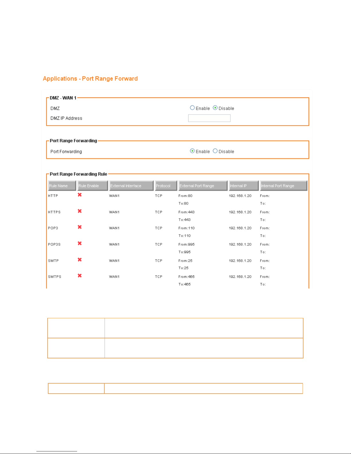
8.1.1 Port Range Forward Settings
1. Click on [Applications] – [Port Range Forward] tab. You will see the following screen.
2. Configure [DMZ] Settings following the instructions below
DMZ
Select Enable to enable DMZ function.
Select Disable to disable DMZ function.
DMZ IP Address
Enter the IP address of a particular host in your LAN which will receive all the
packets originally going to the WAN port / Public IP address above.
3. Configure [Port Range Forwarding] Settings following the instructions below
Port Forwarding
Select Enable / Disable to enable/disable Port Forwarding
Page 65
61
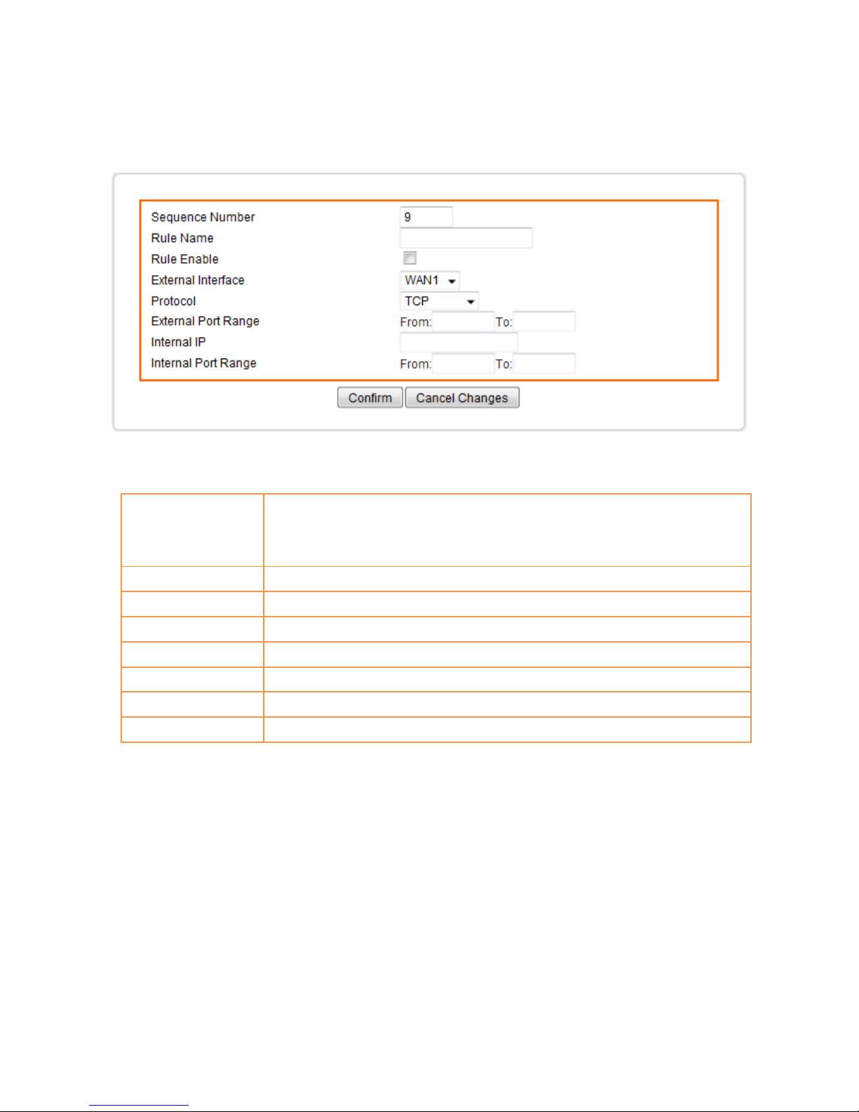
8.1.2 Add Port Range Forwarding Rule
1. Click on [Add] tab. You will see the following screen.
2. Configure [Add Port Range Forwarding Rule] Settings following the instructions below
Sequence Number
This defines the sequences (priorities) of the port forwarding rules. If a
packet fits the conditions setup by the port forwarding rules, the packet
will then be forwarded according to the 1st rule from the top of the list.
Rule Name
Enter the name of the port forwarding rule.
Rule Enable
Enable/Disable this port forwarding rule.
External Interface
Choose WAN1 or WAN2 as the External port forwarding interface.
Protocol
Choose TCP, UDP or TCP/UDP for the rule to be applied.
External Port Range
Set up the External Port Range for the rule to be applied.
Internal IP
Set up the Internal IP for the rule to be applied.
Internal Port Range
Set up the Internal Port Range for the rule to be applied.
Page 66
62
8.2 VIRTUAL HOST SETUP
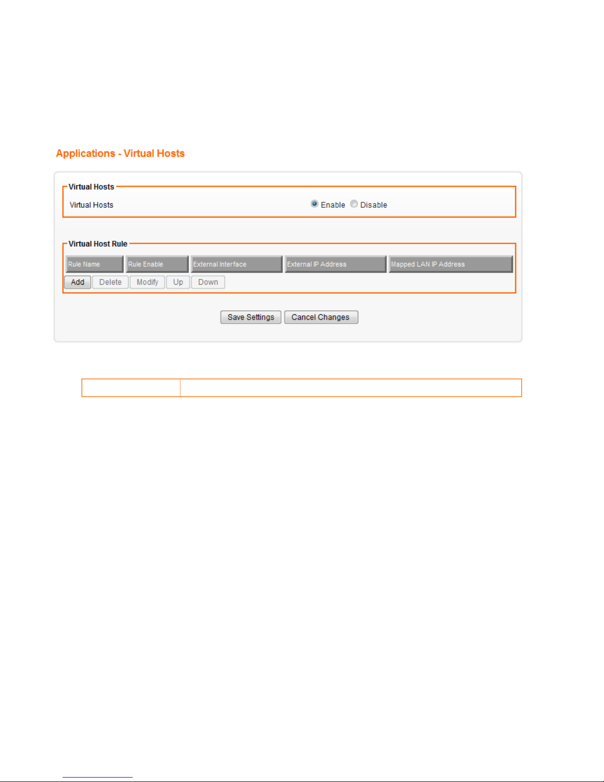
8.2.1 Virtual Host Settings
1. Click on [Applications] – [Virtual Host] tab. You will see the following screen.
2. Configure [Virtual Host] Settings following the instructions below
Virtual Hosts
Select Enable/Disable to enable/disable the Virtual Host function.
Page 67
63
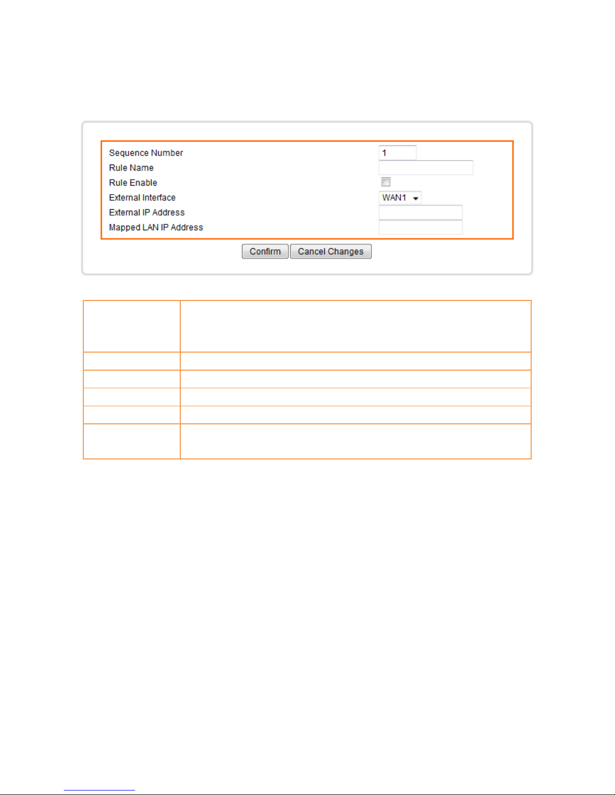
8.2.2 Add Virtual Host
1. Click on [Add] tab. You will see the following screen.
2. Configure [Add Virtual Host] Settings following the instructions below
Sequence Number
This defines the sequences (priorities) of the Virtual Host rule. If a packet fits
the conditions setup by the Virtual Host rule rules, the packet will then be
forwarded according to the 1st rule from the top of the list.
Rule Name
Enter the name of the Virtual Host rule.
Rule Enable
Enable/Disable this Virtual Host rule.
External Interface
WAN1 as the External port forwarding interface.
External IP Address
The external IP addresses offered by the ISP.
Mapped LAN IP
Address
Assign the LAN IP intended to map the specified external WAN IP.
Page 68
64
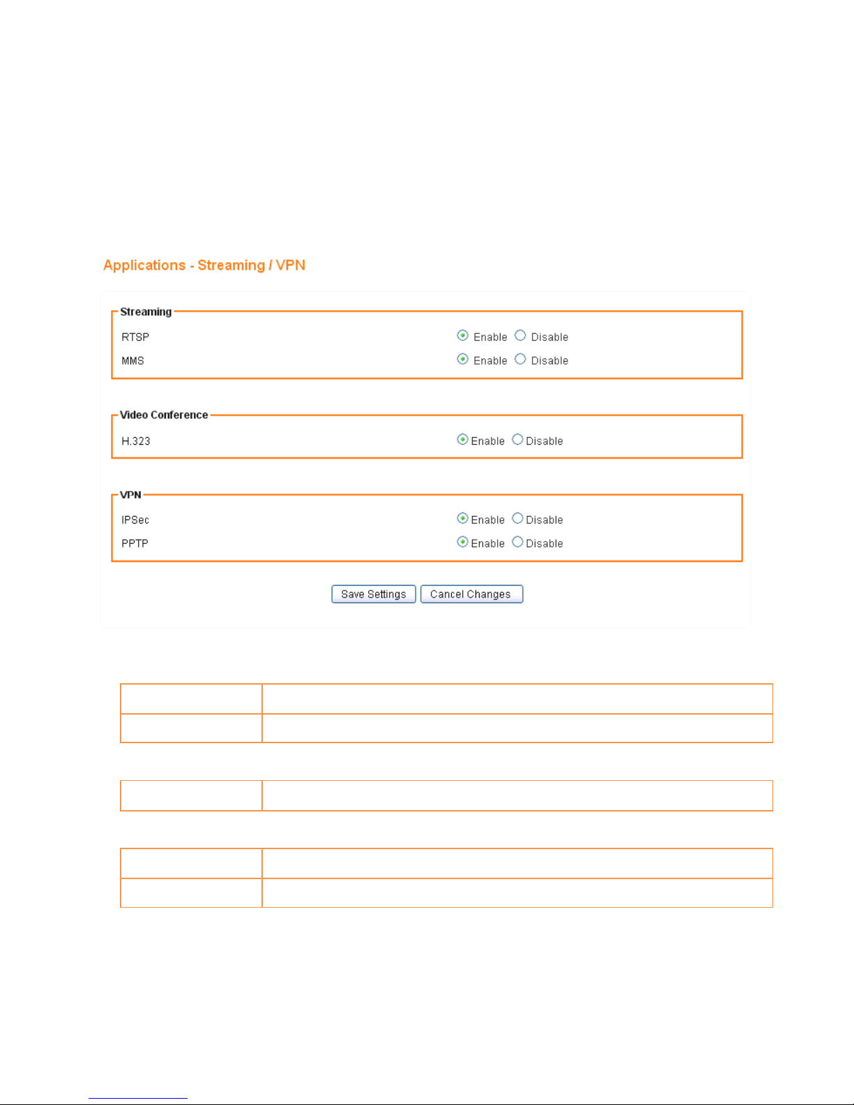
8.3 STREAMING/VPN PASS-THROUGH
You can enhance your media streaming quality by enabling RTSP, MSS, and H.323 protocols. Moreover, VPN
Pass-through functionality can also be enabled.
1. Click on [Applications] – [Streaming / VPN] tab. You will see the following screen.
2. Configure [Streaming] Settings following the instructions below.
RTSP
Select Enable/Disable to enable/disable RTSP
MMS
Select Enable/Disable to enable/disable MMS
3. Configure [Video Conference] Settings following the instructions below
H.323
Select Enable/Disable to enable/disable H.323
4. Configure [VPN] Settings following the instructions below
IPSec Pass-through
Select Enable/Disable to enable/disable IPSec Pass-through
PPTP Pass-through
Select Enable/Disable to enable/disable PPTP Pass-through
Page 69
65
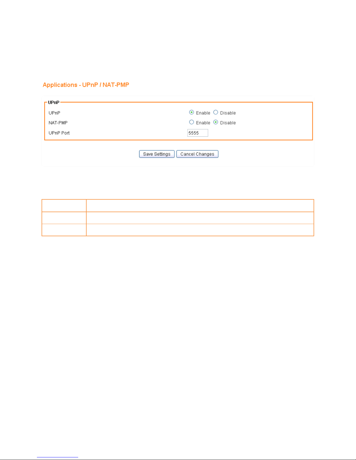
8.4 UPnP/NAT-PMP SETUP
1. Click on [Applications] – [UPnP / NAT-PMP] tab. You will see the following screen.
2. Configure [UPnP] Settings following the instructions below
UPnP
Select Enable/Disable to enable/disable UPnP
NAT-PMP
Select Enable/Disable to enable/disable NAT-PMP
UPnP Port
Enter the number for UPnP port.
Page 70
66
CHAPTER9 AirCloud
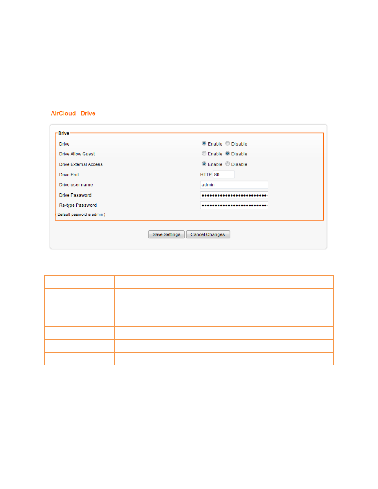
9.1 DRIVE SETUP
1. Click on [AirCloud] – [Drive] tab. You will see the following screen.
2. Configure [Add Port Range Forwarding Rule] Settings following the instructions below
Drive
Select Enable/Disable to enable/disable AirCloud-Drive.
Drive Allow Guest
Select Enable/Disable to enable/disable anonymous login.
Drive External Access
Select Enable/Disable to enable/disable external user login.
Drive Port
Port number of the AirCloud-Driver page for user login.
Drive user name
Username for login to the AirCloud-Driver.
Drive Password
Password for login to the AirCloud-Driver.
Re-type Password
Enter the Password again to confirm.
Page 71
67
CHAPTER10 ADMIN
10.1 MANAGEMENT
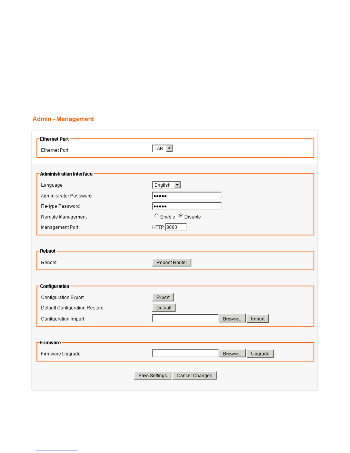
1. Click on [Admin] – [Management] tab. You will see the following screen.
Page 72

68
2. Configure [Administration Interface] Settings based on the instructions listed below.
Language
Select the language of administration Interface you wish to use.
Administrator Password
Maximum input is 36 alphanumeric characters (case sensitive)
* Please change the administrator’s password if the remote
management is enabled. Otherwise, a malicious user can access
the management interface. This user can then have the ability to
change the settings and damage your network access.
Re-type Password
Enter the password again to confirm.
Remote Management
Select Enable to enable Remote Management.
Select Disable to disable Remote Management
If the remote management is enabled, users who are not in the
LAN can connect to AXIMCom Mobile Router and configure it from
the Internet.
Management Port
HTTP port which users can connect to. (default port is 8080)
3. Configure [Configuration] Settings based on the instructions listed below
Configuration Export
Click Export to save your current configuration settings in a file.
Default Configuration
Restore
Click Restore to recover the default system settings.
Configuration Import
Click Browse and Import to load previous configuration settings.
4. Configure [Firmware] Settings based on the instructions listed below
Firmware Upgrade
Click Browse and Upgrade to upgrade the firmware.
Page 73
69
10.2 SYSTEM UTILITIES
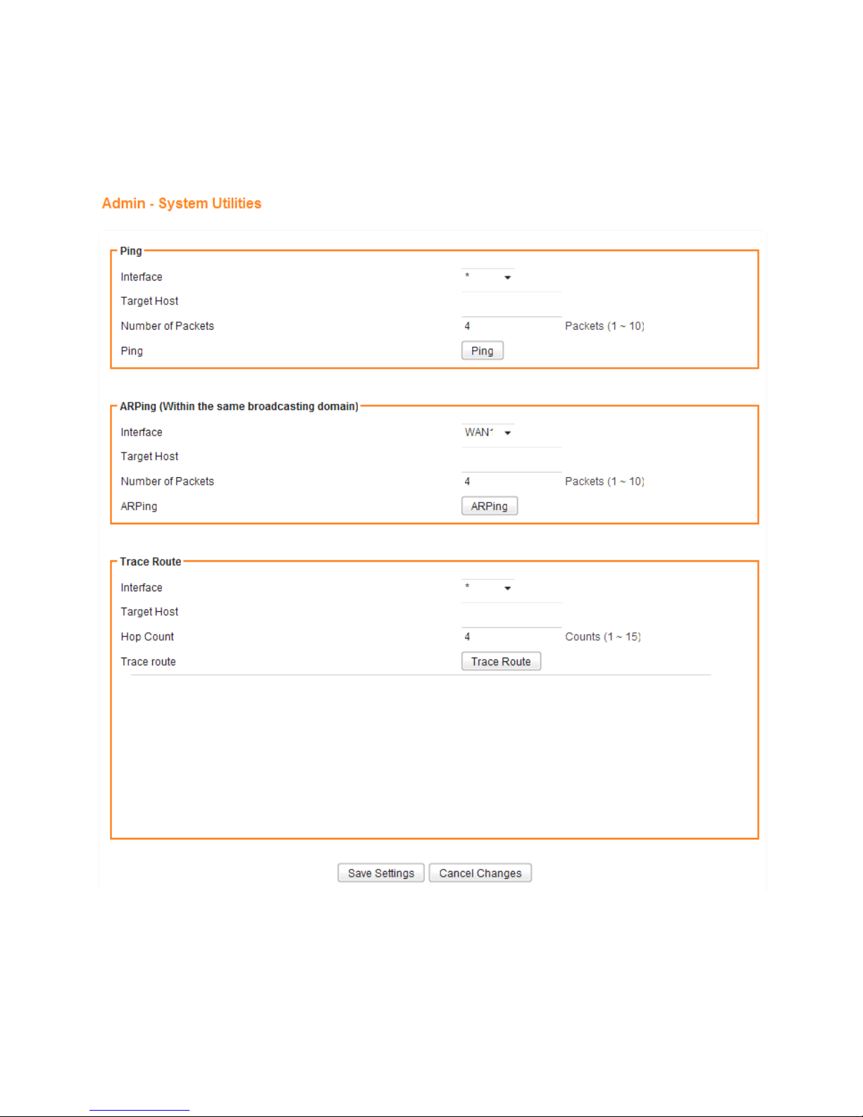
1. Click on [Admin] – [System Utilities] tab. You will see the following screen.
Page 74

70
2. Using the [ping] tool based on the instructions listed below
Interface
Select the interface that use to ping to, ie. LAN, WAN.
Target Host
Enter the IP address to ping to
Number of Packets
Specify the number of the ICMP packets to send out
Ping
Press the tab to start the “ping” actions
3. Using the [ARPing] tool based on the instructions listed below
Interface
Select the interface that use to ARPing to, ie. LAN, WAN.
Target Host
Enter the MAC address to ARPing to
Number of Packets
Specify the number of the ARP request packets to send out
ARPing
Press the tab to start the “ARPing” actions
4. Using the [Trace Route] tool based on the instructions listed below
Interface
Select the interface that use to ARPing to, ie. WAN1, WAN2.
Target Host
Enter the destination IP address / domain name to trace
Hop Count
Specify the Hop number you need to trace
Trace route
Press the tab to start the “Trace Route” actions
Page 75
71
10.3 LOG
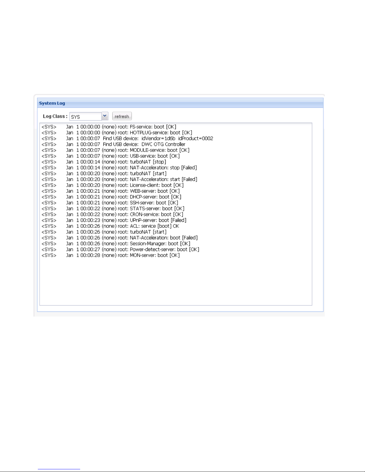
1. Click on [Admin] – [Log] tab. You will see the following screen.
Page 76
72
CHAPTER11 STATUS
You can access and view all the system information regarding AXIMCom Mobile Router from here.
11.1 ROUTER INFORMATION
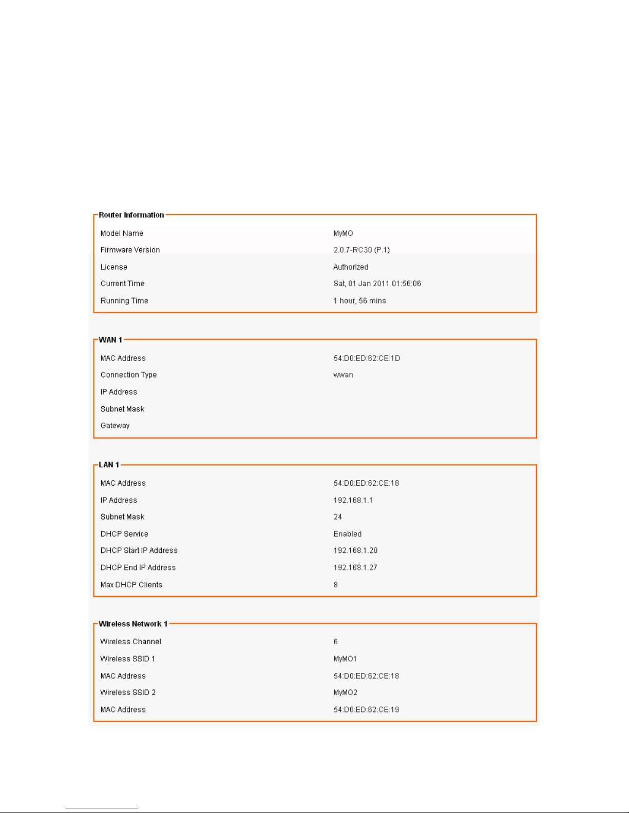
1. Click on [Status] – [Router] tab. You will see the following screen.
Page 77

73
2. Router Information
Model Name
Product model name is shown.
Firmware Version
The firmware version this device is running.
License
“Authorized” should be shown. If “Unauthorized” is shown, please contact the
seller or AXIMCom for a replacement.
Current Time
Current system time
Running Time
The period of time AXIMCom Mobile Router has been running.
3. LAN
MAC Address
MAC Address
IP Address
Internal IP Address
Subnet Mask
The number of subnet mask in the internal network
DHCP Service
DHCP service enabled or disabled
DHCP Start IP Address
DHCP Start IP address
DHCP End IP Address
DHCP End IP address
Max DHCP Clients
The maximum IP addressed which can be assigned to PCs connecting to the
network
4. Wireless Network
Wireless Mode
Access Point
Wireless SSID
SSID of this Wi-Fi station
Wireless Channel
Wireless Channel in use (default is 6)
MAC Address
MAC Address
5. WAN
MAC Address
MAC Address
Connection Type
The current connection type (PPPoE, Static IP, and DHCP)
IP Address
WAN IP Address
Subnet Mask
Number of subnet mask.
Gateway
IP address of the gateway
Page 78
74
11.2 USER/DHCP
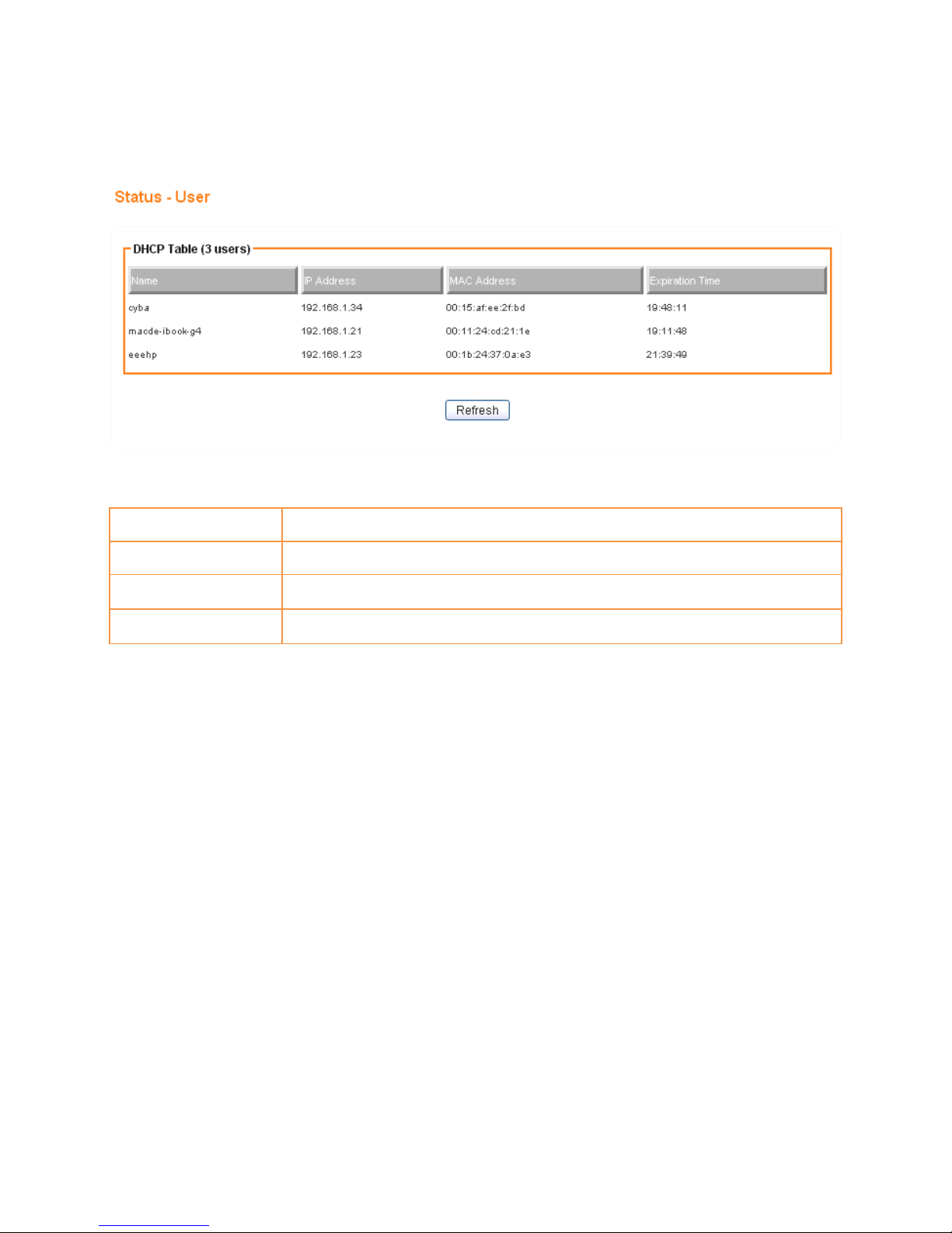
1. Clickon [Status] – [DHCP] tab. You will see the following screen.
Name
DHCP client name
IP Address
IP address which is assigned to this client
MAC Address
MAC address of this client
Expiration Time
The remaining time of the IP assignment
Page 79
75
11.3 USER/ CURRENT
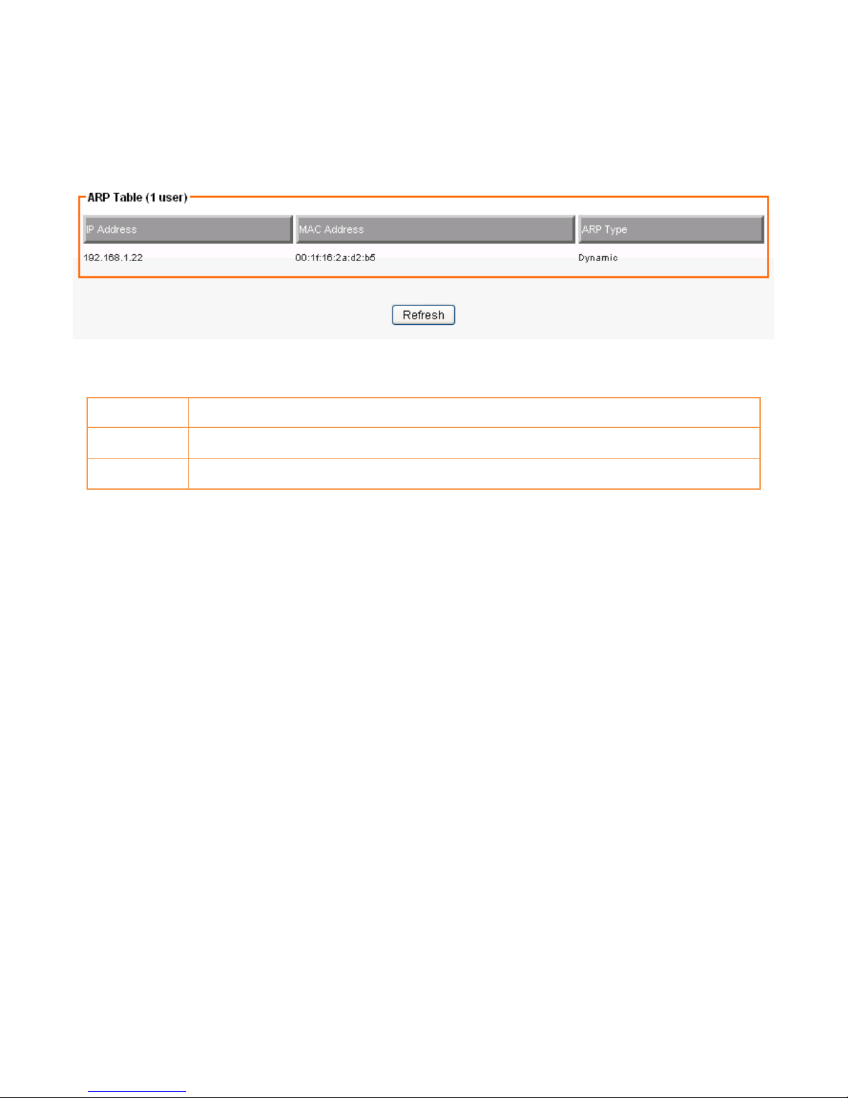
1. Click on [Status] – [Current] tab. You will see the following screen.
IP Address
IP address assigned by Static ARP matching
MAC Address
MAC address in the Static ARP matching
ARP Type
Static or dynamic
 Loading...