

Axial YETI JR. ROCK RACER, YETI JR. Instruction Manual

2
4
4
4
4
3
DTXP4175 USB NiMH Charger and DTXC2031 Battery Instructions
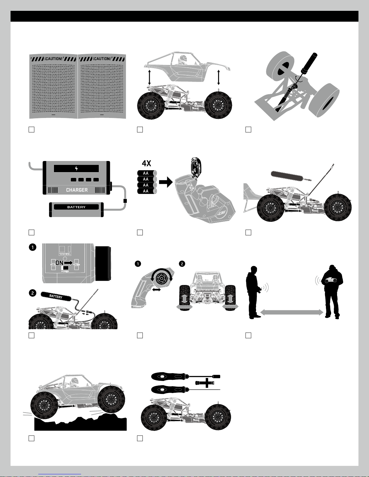
Before using your factory assembled RTR, review the entire instruction manual to become familiar with the vehicle.
This is a quick start guide for care and usage of the charger and battery that comes with the vehicle.
DTXP4175 - Duratrax Onyx USB Charger
NiMH 6C Mini Connector
DTXC2031 - Duratrax NiMH Onyx 7.2V
1300mAh Flat Mini Connector
CAUTION: The DTXP4175 charger is for use
with 6-Cell 7.2v NiMH batteries ONLY and
should not be used with any other batteries.
CAUTION: Never leave the battery unattended
while charging. Always disconnect the battery
and unplug the charger when finished charging.
CAUTION HOT!!!
NiMH batteries may become hot while charging.
Allow to cool before handling the battery.
When using the DTXP4175 charger, the DTCX2031 battery should fully charge in 2-3 hours.
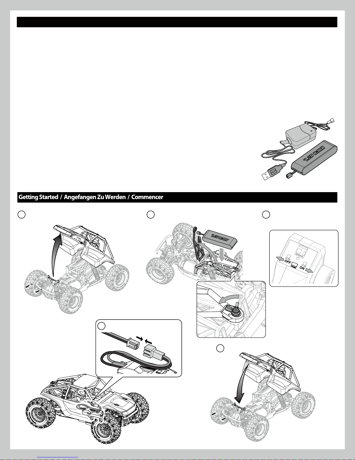
1.
Remove the body clips and body.
Install the battery.
2.
• Remove the battery from the vehicle
before charging.
• Place the battery on a fire resistant surface.
• Avoid any contact with water or other fluids.
1. Connect USB connector to USB power on
PC or USB AC wall adapter.
2. Connect battery to mini connector.
3. Charger will automatically begin charge
process.
Red LED: Charging
Green LED: Finish Charging
3.
Turn on the transmitte
r.
Note:
Power to the vehicle is controlled by
connecting / disconnecting the battery.
4.
Connect the battery to the ESC.
5.
Install the body and body clips.
4
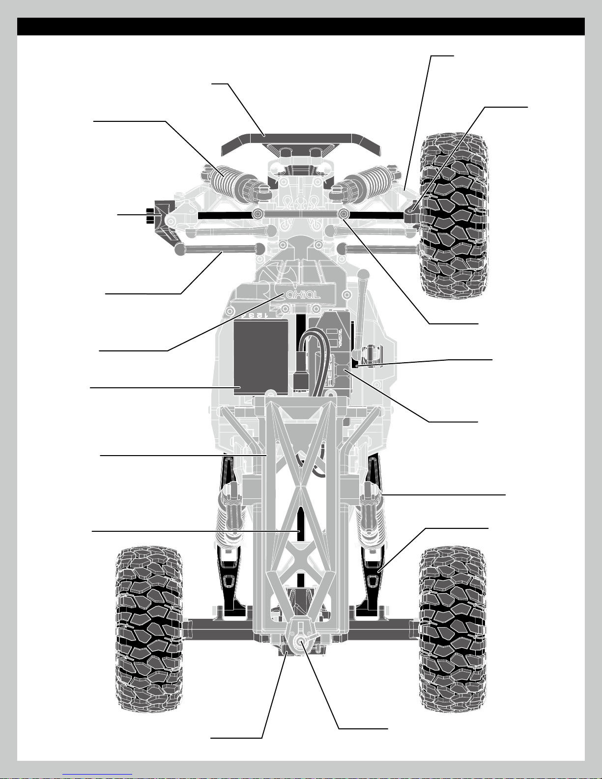
Top View Parts
Front Shock
Absorber
Steering Knuckle
Steering Rack
Front Control Arm
Front Bumper
C-Hub
Spur/Pinion
(Under Cover)
Motor 40T
Battery Tray
Driveshaft
Front Body Mount
Steering Servo
Receiver Box and
Electronic Speed
Control (ESC)
Rear Shock
Absorber
Rear Swing Arm
Rear Differential
Battery Door
5
Getting-Started Checllist
The following checklist is a guide for getting you vehicle running for the first time.
Read ‘Cautions’ in Manual. (Page 2)
Charge battery pack. (Page 4)
Familiarize yourself with vehicle and
its components.
Install 4X AA batteries into Transmitter.
(Page 7)
Before vehicle operation
check all nuts and screws on moving parts
are securely tightened.
Install battery pack in vehicle. (Page 4)
Turn on transmitter first,
then plug in battery
(power ESC) (Page 4)
Drive vehicle, challenge yourself and
have fun!
Check to make sure steering and throttle
operation work correctly. (Page 7)
Maintain vehicle. (Next Page)
6
Range check radio system. (Next Page)
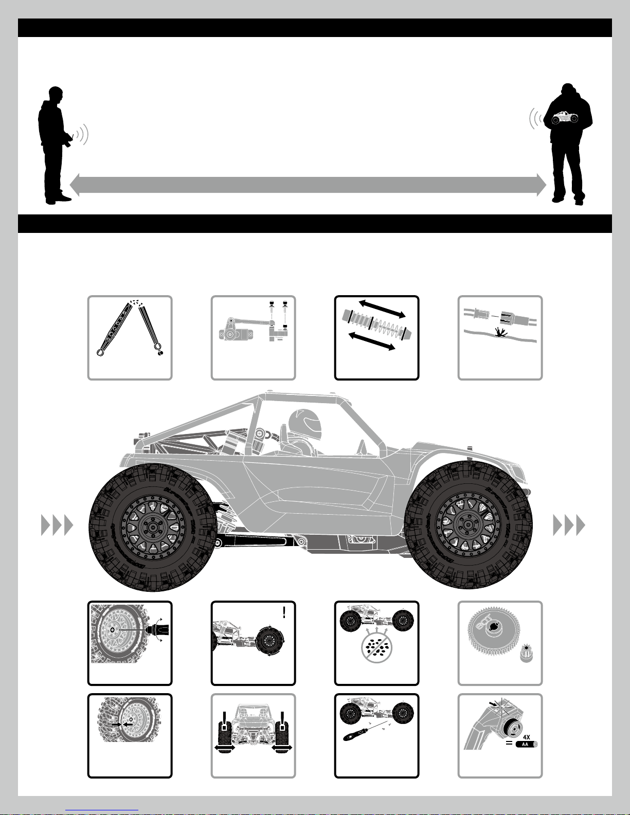
Range-Checking Your Radio System
The radio system should be checked before operating the vehicle to ensure it’s operating properly and has adequate range.
1. Turn on the transmitter first and then the vehicle.
2. Have a friend hold the vehicle while keeping hands and loose clothing away from moving parts.
3. Walk away until you are at the farthest distance you plan to operate the vehicle.
4. Steer the vehicle back and forth and throttle both forward and reverse making sure there is no erratic behavior.
5. If any erratic behavior is exhibited do not operate the vehicle, call customer service for further assistance.
RANGE-CHECKING FOR DISTANCE
Maintaining Your Vehicle
Just like a full size car or truck your RC vehicle must undergo periodic maintenance in order to ensure peak running performance. Preventative
maintenance will also help avoid needless breakages which could result in costly repairs. Below are some suggestions to properly maintain
your vehicle.
REPLACE ANY NOTICEABLE
BENT OR BROKEN PARTS
CHECK FOR WEAR ON
THE BALL JOINTS IN THE
STEERING AND SUSPENSION
(REPLACE IF NECESSARY)
LINKS
INSPECT SHOCK
ABSORBERS FOR SMOOTH
DAMPENED OPERATION
CHECK FOR ANY LOOSE
CONNECTIONS OR FRAYED
WIRING
CHECK WHEEL NUTS MAKING
SURE THEY’RE SNUG
CHECK TIRES MAKING SURE
THE BEADS ARE STILL FIRMLY
BONDED TO THE ENTIRE
CIRCUMFERENCE OF THE RIM
CHECK DRIVELINE FOR
SMOOTH BIND-FREE
OPERATION
CHECK STEERING
OPERATION FOR ANY BINDS
KEEP CHASSIS FREE OF DIRT
CHECK FOR LOOSE SCREWS
ON CHASSIS ESPECIALLY
THE KNUCKLE, C-HUB AND
AXLE LOCKOUT SCREWS
7
OR DEBRIS
INSPECT THE SPUR AND
PINION GEARS FOR DAMAGE
REPLACE TRANSMITTER
AA’S IF THE GREEN LIGHT IS
BLINKING

Warranty Info
AXIAL LIMITED WARRANTY
Your Axial product is warranted to be free of defects in materials and workmanship when new in the factory sealed box. This warranty does not cover damages due to normal wear and tear,
users' failure to perform routine maintenance, error of assembly or installation, modications or addition of aftermarket parts or o pti on par ts. This warranty lasts as long as the origina l
purchaser owns the product and is not transferable (verified by dated itemized sales receipt accompanied with product). In the event of a defect under this warranty, Axial will, at
our discretion, repair or replace the product, provided our inspection indicates that an original defect exists. Axial provides a 10-day warranty from the date of purchase on electronics
(i.e. servo, esc, radio). Axial reserves the right to replace any product which is no longer available with a product of comparable value and function. If Axial determines the repair is not
covered under warranty guidelines, there could be a charge applied for the repair and return shipping charges. Note: Purchasing products from unauthorized distributors may void warranty
and prevent support and service.
INTERNATIONAL CUSTOMER WARRANTY
Please return product to the dealer where the purchase was made. If your Axial product purchase was made through an on-line retailer, any warranty issues must be taken care of by that
retailer. Axial assumes no responsibility for Axial products sold internationally by on-line retailers.
REPAIR
For warranty repair, please contact Axial Customer Service at (877) 64-AXIAL (877-642-9425).
HOURS AVAILABLE:
8:00 am - 5:00 pm Monday through Friday, Central Time.
8
 Loading...