

Page 1

AXP8 GILAMON 2.2
1/8th SCALE 4WD TRAIL BUGGY
INSTRUCTION MANUAL
BEDIENUNGSANLEITUNG
MANUEL D’UTILISATION
MANUALE DI ISTRUZIONI
Scan the QR code and select the Manuals and Support quick links from the
product page for the most up-to-date manual information.
Scannen Sie den QR-Code und wählen Sie auf der Produktseite die Quicklinks
Handbücher und Unterstützung, um die aktuellsten Informationen zu Handbücher.
Scannez le code QR et sélectionnez les liens rapides Manuals and Support sur la
page du produit pour obtenir les informations les plus récentes sur le manuel.
Scannerizzare il codice QR e selezionare i Link veloci Manuali e Supporto dalla
pagina del prodotto per le informazioni manuali più aggiornate.
478400.1
Modified 1/25
AXI-1207
Page 2
EN
NOTICE
All instructions, warranties and other collateral documents are subject to change at the sole discretion of Horizon Hobby, LLC. For up-to-date
product literature, visit horizonhobby.com or towerhobbies.com and click on the support or resources tab for this product.
MEANING OF SPECIAL LANGUAGE
The following terms are used throughout the product literature to indicate various levels of potential harm when operating this product:
WARNING: Procedures, which if not properly followed, create the probability of property damage, collateral damage, and serious injury OR
create a high probability of superficial injury.
CAUTION: Procedures, which if not properly followed, create the probability of physical property damage AND a possibility of serious injury.
NOTICE: Procedures, which if not properly followed, create a possibility of physical property damage AND a little or no possibility of injury.
WARNING: Read the ENTIRE instruction manual to become familiar with the features of the product before operating. Failure to
operate the product correctly can result in damage to the product, personal property and cause serious injury.
This is a sophisticated hobby product. It must be operated with caution and common sense and requires some basic mechanical ability. Failure to
operate this Product in a safe and responsible manner could result in injury or damage to the product or other property. This product is not intended for
use by children without direct adult supervision. Do not use with incompatible components or alter this product in any way outside of the instructions
provided by Horizon Hobby, LLC. This manual contains instructions for safety, operation and maintenance. It is essential to read and follow all the
instructions and warnings in the manual, prior to assembly, setup or use, in order to operate correctly and avoid damage or serious injury.
Age Recommendation: Not for children under 14 years. This is not a toy.
SAFETY PRECAUTIONS AND WARNINGS
As the user of this product, you are solely responsible for operating in a manner that does not endanger yourself and others or result in damage
to the product or property of others.
This model is controlled by a radio signal subject to interference from many sources outside your control. This interference can cause momentary
loss of control, so it is advisable to always keep a safe distance in all directions around your model as this margin will help avoid collisions or injury.
• Never operate your model with low transmitter batteries.
• Always operate your model in open spaces away from full-size
vehicles, traffic and people.
• Never operate the model in the street or in populated areas for any
reason.
• Carefully follow the directions and warnings for this and any optional
support equipment (chargers, rechargeable battery packs, etc.) you use.
• Keep all chemicals, small parts and anything electrical out of the
reach of children.
• Never lick or place any portion of the model in your mouth as it could
cause serious injury or even death.
• Exercise caution when using tools and sharp instruments.
WARNING AGAINST COUNTERFEIT PRODUCTS: Always purchase from a Horizon Hobby, LLC authorized dealer to ensure
authentic high-quality Spektrum product. Horizon Hobby, LLC disclaims all support and warranty with regards, but not limited to,
compatibility and performance of counterfeit products or products claiming compatibility with Spektrum technology.
• Take care during maintenance as some parts may have sharp edges.
• Immediately after using your model, do NOT touch equipment
such as the motor, electronic speed control and battery, because
they generate high temperatures. You may burn yourself seriously
touching them.
• Do not put fingers or any objects inside rotating and moving parts, as
this may cause damage or serious injury.
• Always turn on your transmitter before you turn on the receiver in the
car. Always turn off the receiver before turning your transmitter off.
• Keep the wheels of the model off the ground when checking the
operation of the radio equipment.
2
Page 3
TABLE OF CONTENTS
Water-resistant Vehicle with Waterproof Electronics .............................. 3
Box Contents.....................................................................................................4
Required Equipment ........................................................................................ 4
Recommended tools ........................................................................................4
Getting started checklist.................................................................................5
Vehicle parts ..................................................................................................... 5
Charge the vehicle battery ............................................................................. 6
Install the transmitter batteries ..................................................................... 6
Transmitter functions ...................................................................................... 6
Install the vehicle battery ............................................................................... 7
Power On and Off .............................................................................................8
Control Test ....................................................................................................... 8
Range-check the radio system ......................................................................8
Axial Selectable Drive (ASD) ......................................................................... 9
LED Rock Lights ..............................................................................................10
vehicle maintenance ..................................................................................... 11
Binding .............................................................................................................12
LED Indicator and Motor Sounds ................................................................ 12
Transmitter and ESC Calibration ..................................................................12
Troubleshooting ..............................................................................................13
Limited Warranty ............................................................................................14
Warranty and Service Contact Information .............................................. 14
FCC Information ..............................................................................................15
IC Information ................................................................................................. 15
Compliance Information for the European Union ..................................... 15
Parts Lists ........................................................................................................63
Optional Parts ................................................................................................. 65
Recommended................................................................................................67
WATER-RESISTANT VEHICLE WITH WATERPROOF ELECTRONICS
EN
Your new Horizon Hobby vehicle has been designed and built with
a combination of waterproof and water-resistant components to
allow you to operate the product in many “wet conditions,” including
puddles, creeks, wet grass, snow and even rain.
While the entire vehicle is highly water-resistant, it is not completely
waterproof and your vehicle should NOT be treated like a submarine.
The various electronic components used in the vehicle, such as the
Electronic Speed Control (ESC), servo(s) and receiver are waterproof,
however, most of the mechanical components are water-resistant and
should not be submerged.
Metal parts, including the bearings, hinge pins, screws and nuts, as
well as the contacts in the electrical cables, will be susceptible to
corrosion if additional maintenance is not performed after running in
wet conditions. To maximize the long-term performance of your vehicle
and to keep the warranty intact, the procedures described in the “Wet
Conditions Maintenance” section below must be performed regularly
if you choose to run in wet conditions. If you are not willing to perform
the additional care and maintenance required, then you should not
operate the vehicle in those conditions.
CAUTION: Failure to exercise caution while using this
product and complying with the following precautions could
result in product malfunction and/or void the warranty.
GENERAL PRECAUTIONS
• Read through the wet conditions maintenance procedures and make
sure that you have all the tools you will need to properly maintain your
vehicle.
• Not all batteries can be used in wet conditions. Consult the battery
manufacturer before use. Caution should be taken when using Li-Po
batteries in wet conditions.
• Most transmitters are not water-resistant. Consult your transmitter’s
manual or the manufacturer before operation.
• Never operate your transmitter or vehicle where lightning may be
present.
• Do not operate your vehicle where it could come in contact with salt
water (ocean water or water on salt-covered roads), contaminated
or polluted water. Salt water is very conductive and highly corrosive,
so use caution.
• Even minimal water contact can reduce the life of your motor if it
has not been certified as water-resistant or waterproof. If the motor
becomes excessively wet, apply very light throttle until the water is
mostly removed from the motor. Running a wet motor at high speeds
may rapidly damage the motor.
• Driving in wet conditions can reduce the life of the motor. The
additional resistance of operating in water causes excess strain. Alter
the gear ratio by using a smaller pinion or larger spur gear. This will
increase torque (and motor life) when running in mud, deeper puddles,
or any wet conditions that will increase the load on the motor for an
extended period of time.
WET CONDITIONS MAINTENANCE
• Drain any water that has collected in the tires by spinning them at high
speed. With the body removed, place the vehicle upside down and pull
full throttle for a few short bursts until the water has been removed.
CAUTION: Always keep hands, fingers, tools and any loose
or hanging objects away from rotating parts when performing
the above drying technique.
• Remove the battery pack(s) and dry the contacts. If you have an air
compressor or a can of compressed air, blow out any water that may
be inside the recessed connector housing.
• Remove the tires/wheels from the vehicle and gently rinse the mud
and dirt off with a garden hose. Avoid rinsing the bearings and
transmission.
NOTICE: Never use a pressure washer to clean your vehicle.
• Use an air compressor or a can of compressed air to dry the vehicle
and help remove any water that may have gotten into small crevices or
corners.
• Spray the bearings, drive train, fasteners and other metal parts with
a water-displacing light oil. Do not spray the motor.
• Let the vehicle air dry before you store it. Water (and oil) may
continue
to drip for a few hours.
• Increase the frequency of disassembly, inspection and lubrication of
the following:
- Front and rear axle hub assembly bearings.
- All transmission cases, gears and differentials.
- Motor—clean with an aerosol motor cleaner and re-oil the
bushings
with lightweight motor oil.
3
Page 4
EN
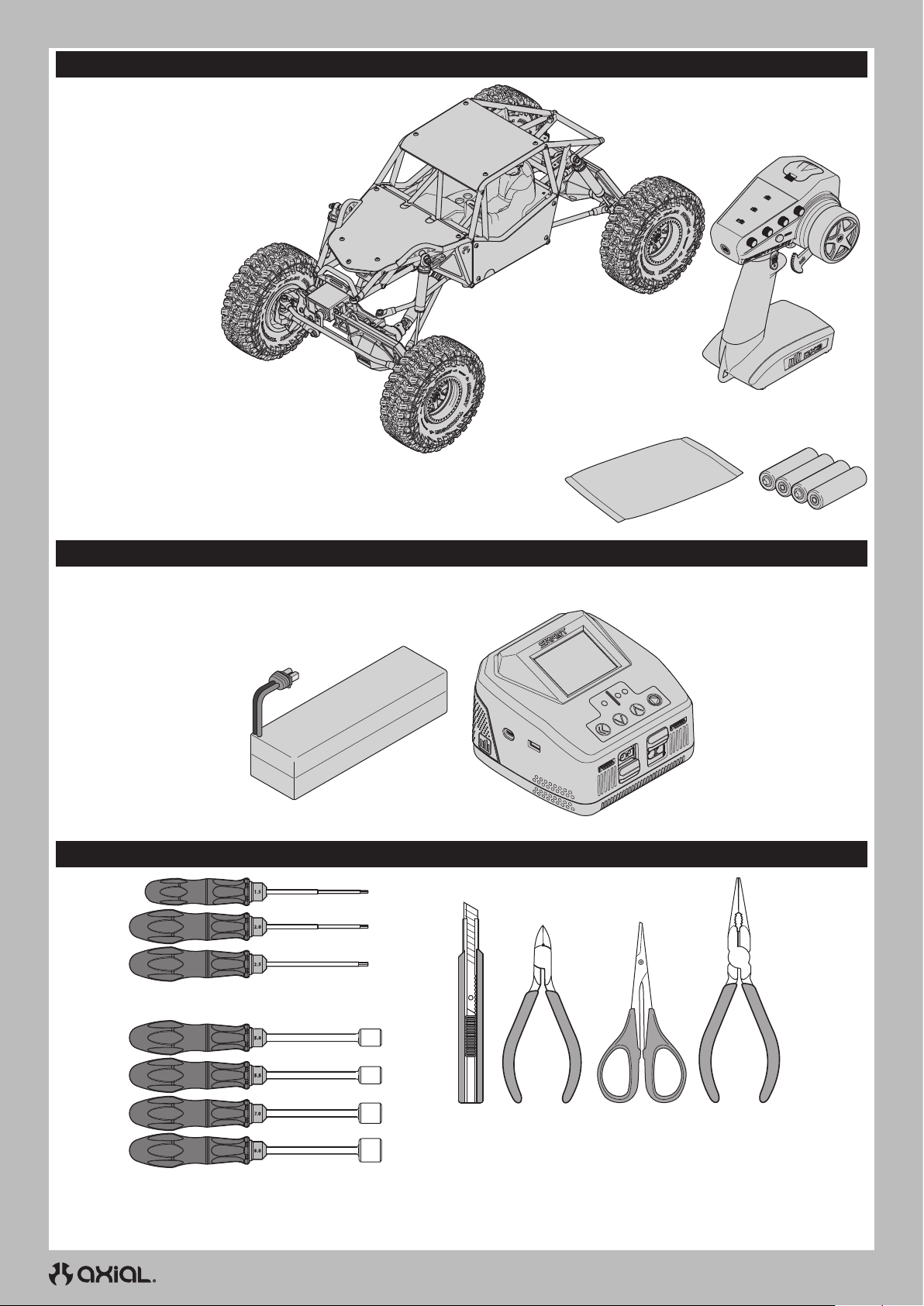
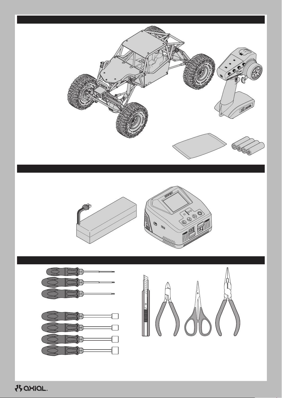
BOX CONTENTS
• Spektrum DX3 Smart Transmitter w/Thumb Steer (SPMR2340T)
• Gilamon™ 2.2 4WD Trail Buggy RTR
- Boulder 550, 21T Brushed Electric Motor (AXI-2156)
- S682 20kg servo , steel gear 25T (SPMS682)
- SX117AX Micro Servo Metal Gear/Case,
250mm Lead (SPMSSX117AX)
- SR515 DSMR 5 Channel Receiver
(SPMSR515)
- Firma 70A Brushed Smart WP ESC
(SPMXSE1070)
• (4) AA Alkaline batteries
• Parts Bag • (4) AA Alkaline
batteries
REQUIRED EQUIPMENT
• 3S LiPo Battery
(IC3™ Connector Required)
RECOMMENDED TOOLS
• Hex Drivers (1.5, 2.0, 2.5mm)
• Battery charger compatible with
the chosen vehicle battery
• Nut Drivers (5.0, 5.5, 7.0, 8.0mm)
• Hobby
Knife
4
• Side Cutter • Curved
Scissors
• Long-nose Plier
Page 5
GETTING STARTED CHECKLIST
EN
Read the manual
Familiarize yourself with the vehicle and its components
Check all screws, especially the driveshaft setscrews, for
tightness from the factory
Charge the vehicle battery
Install 4 AA batteries in the transmitter
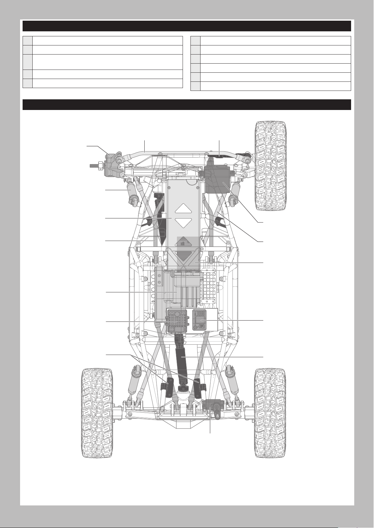
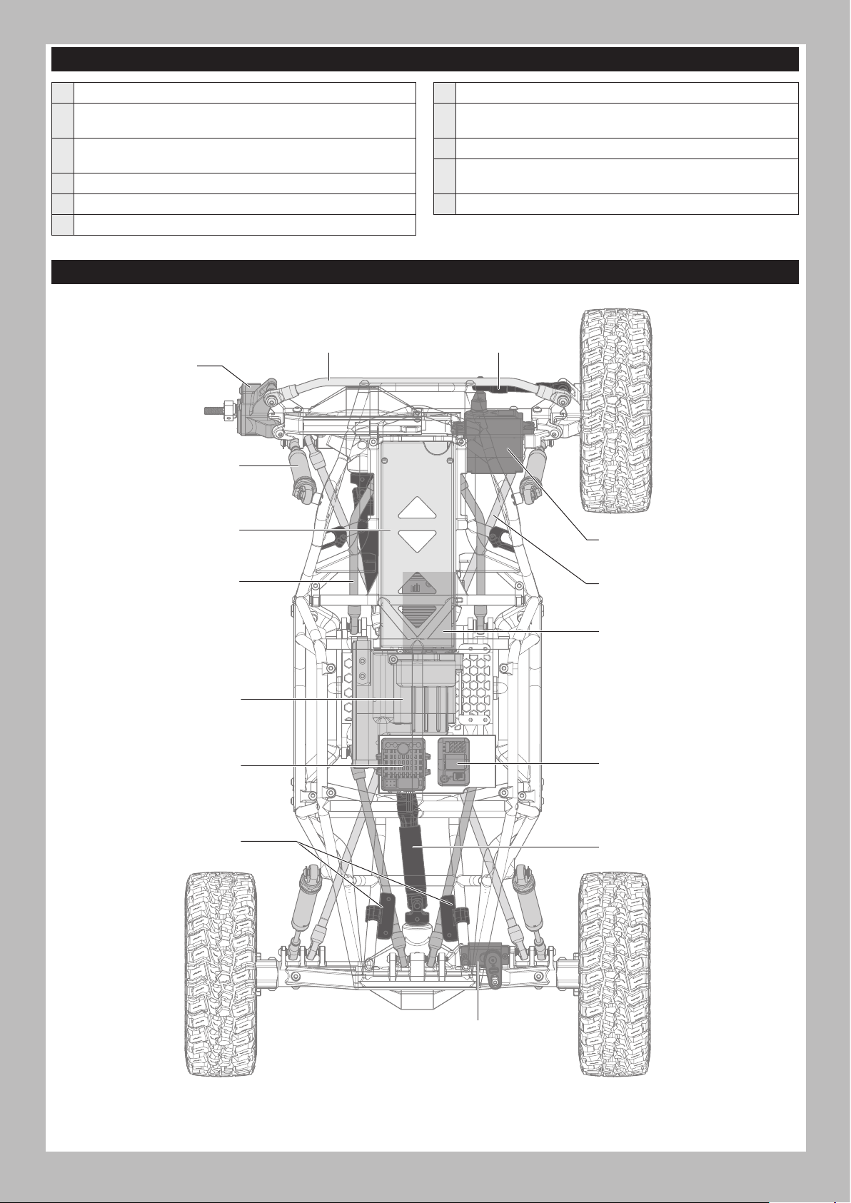
VEHICLE PARTS
Steering Link
Steering Knuckle
Shock Absorber
Battery Tray
Power on the transmitter
Install the vehicle battery in the vehicle
Check for proper function of the throttle and steering
Range check the radio system
Drive the vehicle, challenge yourself and have FUN!
Perform any necessary vehicle maintenance
Drag Link
Steering Servo
Upper 4-link
Transmission
Electronic Speed Control (ESC)
Adjustable LED Rock Light
Lower 4-link
Motor
Receiver
Driveshaft
5
ASD Servo
Page 6
EN
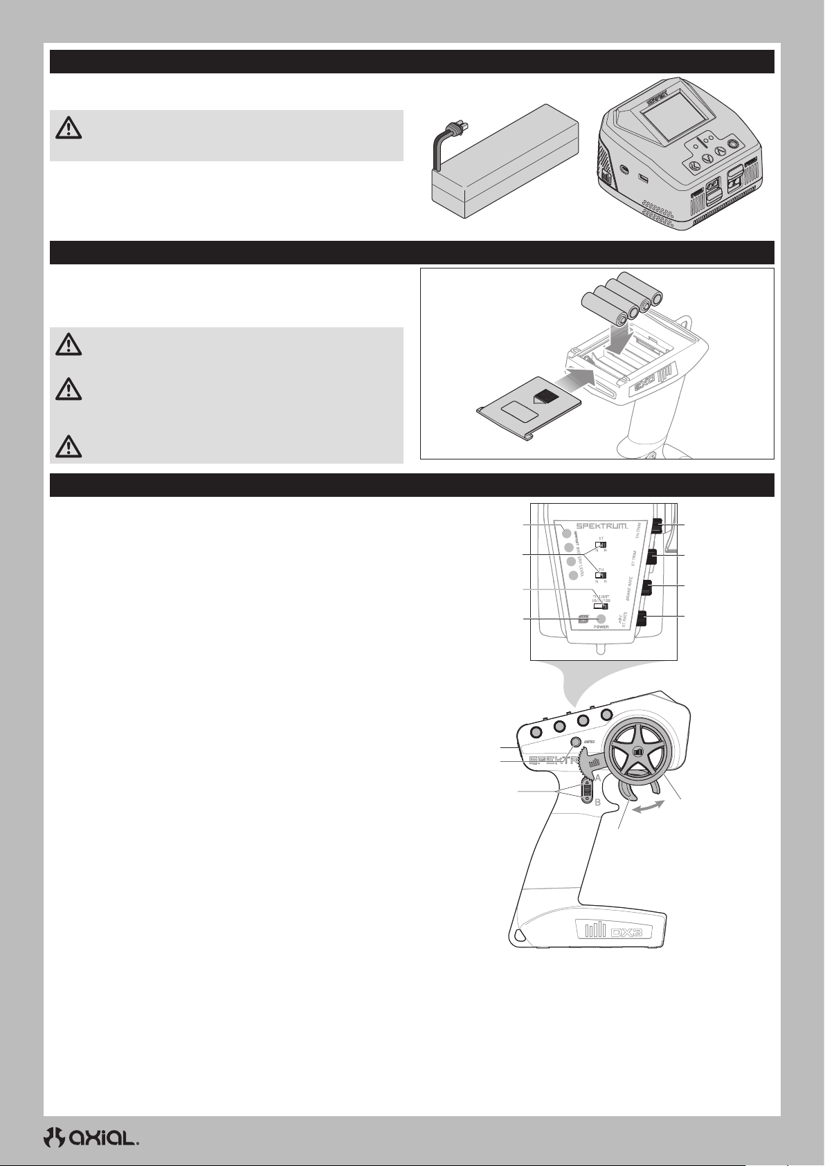
CHARGE THE VEHICLE BATTERY
Follow the manufacturer’s directions for your charger to properly
charge the vehicle battery.
CAUTION: Only use chargers designed to charge the chosen
battery type. Using an incompatible charger or incorrect charge
settings could result in fire causing person injury or property damage.
INSTALL THE TRANSMITTER BATTERIES
This transmitter requires 4 AA batteries.
1. Remove the battery cover from the transmitter.
2. Install the batteries as shown.
3. Install the battery cover.
CAUTION: NEVER remove the transmitter batteries while the
model is powered on. Loss of model control, damage, or injury
may occur.
CAUTION: If using rechargeable batteries, charge only
rechargeable batteries. Charging non-rechargeable batteries
may cause the batteries to burst, resulting in injury to persons and/or
damage to property.
CAUTION: Risk of explosion if battery is replaced by an incorrect
type. Dispose of used batteries according to national regulations.
TRANSMITTER FUNCTIONS
Right Rear Selectable Drive (ASD function)
A.
Right Rear Selectable Drive (ASD function)
Left Rear Selectable Drive (ASD function)
B.
Left Rear Selectable Drive (ASD function)
Throttle/Brake
C.
Steering Wheel
D.
Steering Rate
E.
Adjusts the end point of the steering
Brake Rate
F.
Adjusts the braking end point.
Steering Trim
G.
Adjusts the steering center point. Normally, the steering trim is
adjusted until the vehicle tracks straight.
Throttle Trim
H.
Adjusts the throttle neutral point
SMART Battery Level Indicator
I.
Servo Reversing
J.
To reverse the Throttle (TH) or Steering (ST) channel, switch
the position of the correlating switch—“N” is for normal, “R”
is for reverse.
Throttle Limit
K.
Limits throttle output to 50/75/100%
Select 50% or 75% for less experienced drivers or when you
are driving the vehicle in a small area.
Power LED
L.
• Solid red lights: Indicates radio connectivity and
adequate battery power
• Flashing red lights: Indicates the battery voltage is
critically low. Replace batteries
Power Button
M.
Bind Button
N.
I
J
K
L
M
N
A/B
C
H
G
F
E
D
6
Page 7
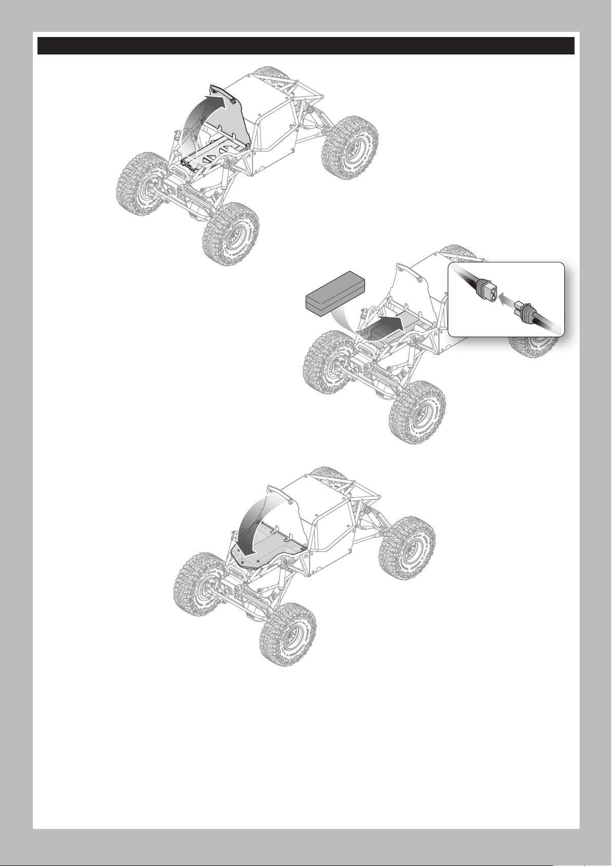
INSTALL THE VEHICLE BATTERY
1. Pull up from under the front bar of the hood
to access the battery tray.
2. Install the recommended vehicle battery into the battery
compartment with the power leads toward the front.
3. Connect the battery power lead to the ESC connector, noting
proper polarity.
4. Secure the battery in the compartment with the installed hook
and loop strap.
TIP: Keep the battery lead connection from moving by
looping the hook and loop strap over the power lead.
EN
5. Press the front of the hood down until it snaps securely into place
on both front corners.
7
Page 8
EN
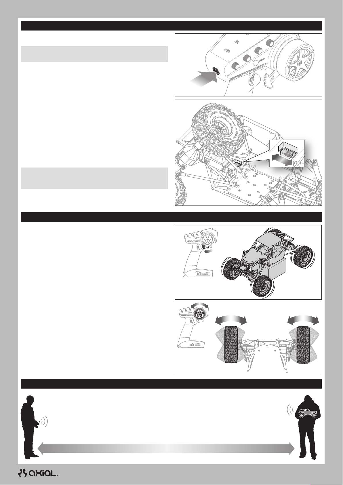
POWER ON AND OFF
POWER ON
1. Power on the transmitter.
NOTICE: Always power on the transmitter before powering on the
vehicle.
2. Power on the vehicle by sliding the switch toward the rear of the
vehicle.
POWER OFF
1. Power off the vehicle by sliding the switch toward the front of the
vehicle.
NOTICE: Always power off the vehicle before powering off the
transmitter. Powering off the transmitter first may result in loss of
control.
2. Power off the transmitter.
3. Disconnect the battery from the ESC.
4. Remove the battery from the vehicle to charge or store.
Power
CONTROL TEST
Perform a control test with the vehicle wheels off the ground.
• To make the wheels roll forward, pull the trigger.
IMPORTANT: The standard transmission gearing gives the rear
axle of the vehicle ‘underdrive.’ The rear wheels rotate slower than
the front wheels.
• To reverse the wheels, wait for the wheels to stop, then push the
trigger forward.
• If the wheels rotate after the vehicle is powered ON, adjust the
TH TRIM knob until they don’t rotate without throttle input.
• Turn the transmitter steering wheel left and right, checking the
vehicle wheels turn the corresponding direction with the transmitter
input.
Place the vehicle on the ground and slowly input throttle:
• When the vehicle is rolling forward, it should maintain a straight line
without any steering input. If it does not, adjust the ST TRIM knob left
or right until the vehicle maintains a straight line without having to
correct with the steering wheel.
RANGE-CHECK THE RADIO SYSTEM
The radio system should be checked before operating the vehicle to ensure proper operation and adequate range.
1. Power on the transmitter.
2. Connect the vehicle battery and power on the vehicle.
3. Have a friend hold the vehicle while keeping hands and loose clothing away from moving parts.
4. Walk away until you are at the maximum planned operating distance from the vehicle.
5. Turn the steering wheel side to side and operate the throttle, both forward and reverse, checking for any erratic behavior.
6. If any erratic behavior is exhibited, DO NOT operate the vehicle. Call customer service for assistance.
8
Page 9
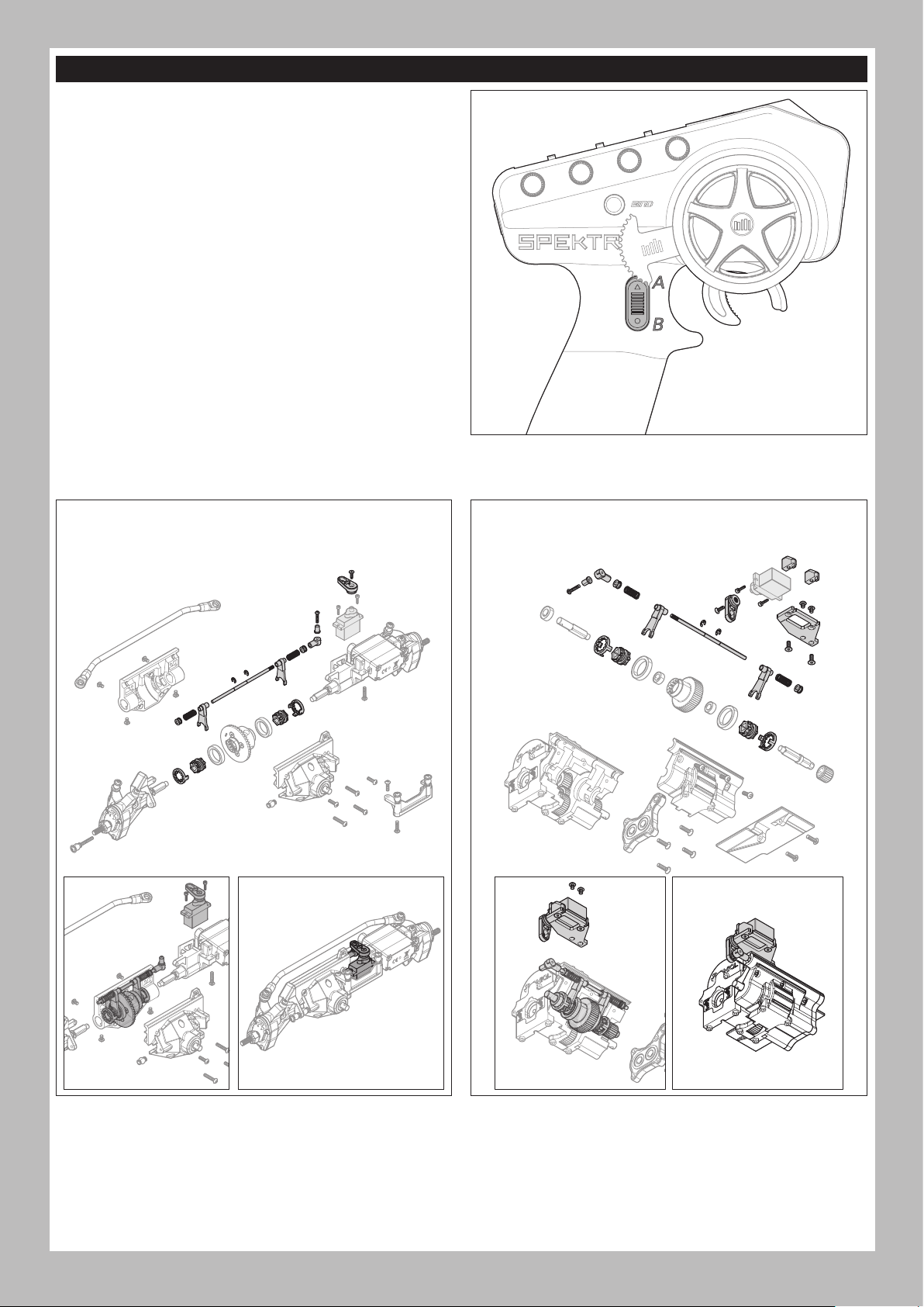
AXIAL SELECTABLE DRIVE (ASD)
The rear axle of the vehicle has Axial Selectable Drive (ASD) preinstalled. ASD allows the driver to lock either the left or right rear
wheel, allowing the vehicle to make very tight radius turns by pivoting
around the “locked” wheel.
To engage ASD:
1. Press and hold either the A or B button.
• A engages the left wheel lock
• B engages the right wheel lock
2. Turn the steering wheel and slowly apply or intermittently ‘blip’ the
throttle to pivot the vehicle around the locked wheel.
TIP: Turning the steering wheel in the direction of the locked
wheel creates a tight turn in that direction.
Turning the steering wheel opposite from the locked wheel
creates a slow slide away from the locked wheel.
3. Release the A or B button and throttle to ‘unlock’ the wheel.
TIP: It may be necessary to bump reverse slightly to release
ASD.
ADDITIONAL ASD FUNCTIONS (OPTIONAL)
With the additional purchase of a servo and the ASD Parts Set: AXP8
(AXI-2191), Axial Selectable Drive can be added to either the front axle,
the transmission, or both with the purchase of two sets and servos.
IMPORTANT: Controlling the additional optional functions requires
a transmitter with more than three channels, such as the Spektrum™
DX6 Rugged 6-channel DSMR transmitter (SPMR6215).
EN
FRONT AXLE ASD INSTALLATION (OPTIONAL)
To enable front left and right selectable drive
Servo not included (SPMSSX117AX recommended)
TRANSMISSION ASD INSTALLATION (OPTIONAL)
To enable front and rear selectable drive
Servo not included (SPMSSX117AX recommended)
9
Page 10
EN
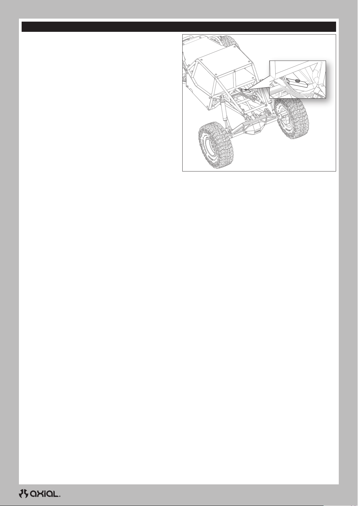
LED ROCK LIGHTS
The vehicle is supplied with color selectable RGB LED rock lights
installed.
To operate the lights:
1. Power on the vehicle.
2. Press the light control button, located at the rear of the center roll
cage as shown. The LED lights power on red with the first press.
3. Cycle through the seven available colors by pressing the control
button repeatedly until the desired color is displayed.
4. Power off the lights by cycling through the colors with the control
button until the lights power off.
LED SEQUENCE:
1. Red
2. Green
3. Blue
4. Yellow
5. Purple
6. Teal
7. White
8. Off
10
Page 11
EN
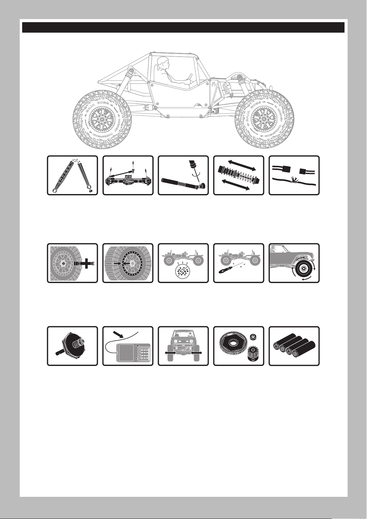
VEHICLE MAINTENANCE
Just like a full size car or truck your RC vehicle must undergo periodic maintenance in order to ensure peak performance. Preventative maintenance
will also help avoid needless breakages which could result in costly repairs. Below are some suggestions to properly maintain your vehicle.
Replace any
noticeably bent or
broken parts
Check the wheel nuts
for tightness
If applicable, check
the slipper clutch for
proper operation
Check for wear on
the ball joints in
the steering and
suspension links
(replace if necessary)
Ensure the wheel
beads are still firmly
bonded around the
entire circumference
of the rim
Check the receiver
antenna for damage
Check driveshaft
set screws and
apply thread
locking compound if
necessary
Clean the chassis of
any dirt and debris
Check the steering
operation for any
binding
Inspect shock
absorbers for smooth
dampened operation
Check for loose
screws on the chassis,
especially the knuckle,
C-hub and axle lockout
screws
Inspect the spur
and pinion gears for
damage
Check for any loose
connections or frayed
wiring
Check the driveline
for smooth, bind free
operation
Replace the
transmitter batteries
when indicated by
the transmitter, as
described in the
Transmitter Functions
section
11
Page 12
EN
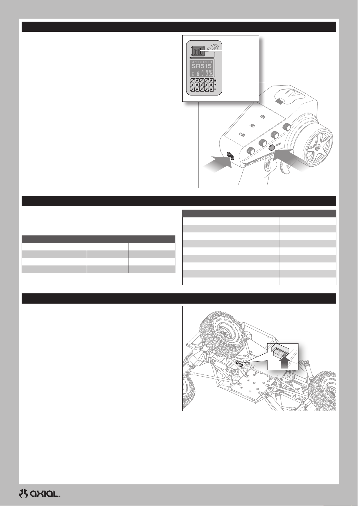
BINDING
Binding is the process of programming the receiver to recognize the
GUID (Globally Unique Identifier) code of a single specific transmitter.
The transmitter and receiver are bound at the factory. If you need to
rebind, follow the instructions below.
1. Connect a fully charged battery pack to the ESC.
2. Press and hold the bind button on the receiver.
3. Power on the vehicle. The red LED on the receiver flashes,
indicating the receiver is in bind mode.
4. Release the bind button.
5. With the throttle trigger at neutral, press and hold the transmitter
bind button while powering on to put the transmitter in bind mode.
IMPORTANT: The throttle should be at neutral to set failsafe.
6. The bind process is complete when the green LED on the receiver
remains lit.
You must rebind when different failsafe positions are needed e.g.,
when throttle or steering reversing has been changed.
Bind Button
Bind ButtonPower Button
LED INDICATOR AND MOTOR SOUNDS
When the ESC is powered on, the LED blinks and the motor emits
a series of beeps to indicate its status. The battery mode selection
displays first, followed by the drag brake setting, and then the
indication the ESC is ready to operate.
FEATURE LED STATUS MOTOR SOUND
Ni-MH/Ni-CD Battery 1 Blink 1 Short Beep
2S Li-Po Battery 2 Blinks 2 Short Beeps
3S Li-Po Battery 3 Blinks 3 Short Beeps
ESC Ready 1 Long Blink 1 Long Beep
TRANSMITTER AND ESC CALIBRATION
It is important to calibrate the ESC to the transmitter so the ESC
matches the throttle range on your transmitter. Failure to calibrate the
ESC to your radio system will result in the ESC not working correctly.
Set the Fail Safe on your radio to a neutral position to ensure the motor
stops in the event of a signal loss.
1. Power ON the transmitter.
2. Set the Throttle Limit switch to 100%, and center the throttle trim
before proceeding with calibration.
3. Connect a battery to the ESC.
4. Press and hold the programming button on the switch case while
powering on the ESC.
The red LED on the ESC will flash, and the motor will beep.
5. Release the programming button within 3 seconds.
IMPORTANT: The ESC will enter programming mode if the
programming button is not released within 3 seconds. If the ESC
does enter programming mode, power off the vehicle and return
to step 4.
6. With the throttle trigger and trim in the neutral position, press and
release the programming button. The red LED will flash once, and
the motor will emit 1 tone.
TIP: Beeps from the motor may be difficult to hear. Use the LED
status to verify settings.
7. Pull the throttle trigger to full throttle. Press and release the
programming button. The red LED will flash twice, and the motor
will emit 2 tones.
DURING OPERATION LED STATUS
Stop OFF
Forward Partial Throttle Blinks
Full Throttle Solid
Reverse Partial Throttle Blinks
Full Throttle Solid
Partial Brake Blinks
Full Brake Solid
Battery Low Voltage Blinks
Overheat Blinks
8. Push the throttle trigger to full reverse. Press and release the
programming button. The red LED will flash 3 times, and the motor
will emit 3 tones.
9. Power OFF the system with the ON/OFF switch.
10. Power ON the system with the ON/OFF switch. The system is
ready for operation
12
Page 13

TROUBLESHOOTING
PROBLEM POSSIBLE CAUSE SOLUTION
Your transmitter and receiver are too
close together
You are near metal objects Move to an area with less metal
The system will not connect
The receiver goes into failsafe a short
distance away from the transmitter
The receiver stops responding during
operation
Vehicle does not move
Loss of vehicle control
Steering and/or throttle function is
reversed
ESC ON - No motor function, audible tone
or LED
Motor- Stops and LED blinks
Motor- Accelerates irregularly
Motor- Does not turn continuously in
response to throttle
Motor- Slows but will not stop Incorrect transmitter/ESC calibration
Steering servo- Operates; motor does not
run
Steering/motor- not functioning
Vehicle- Does not operate at full speed
The receiver is bound to a different
model memory
Your transmitter was placed into bind
mode and is no longer bound to your
receiver
Check for damage on the receiver
antenna
Low receiver battery voltage. If the
battery voltage is low, it may drop
below 3.5V momentarily, causing the
receiver to brown-out, then reconnect
Loose or damaged wires or connectors
between battery and receiver
Batteries are not installed properly in
the transmitter
Weak or no battery in the vehicle Install a freshly charged vehicle battery
Damaged motor Replace the motor
Frayed or broken wiring Replace any damaged wiring
ESC is shut down by heat protection circuit
Improper antenna placement
Weak or no batteries in the transmitter
or vehicle
Neutral or trim position is incorrect Adjust the steering trim
Receiver and/or battery not connected
properly
Servo travel is reversed at the transmitter Set the transmitter servo reversing switch to the correct position
Motor wires are not connected properly Check all motor wires for correct polarity and secure connection
Battery/connection issue Recharge/replace battery. Secure all connections
Damaged ESC/switch Repair/replace ESC switch/ESC
Damaged motor Repair/replace
Low voltage protection When the ESC LED blinks, recharge/replace battery
Overheat protection
Battery issue Repair damaged wiring/replace battery
Incorrect gearing Adjust/replace gearing
Worn or damaged motor Repair/replace motor
ESC/motor damaged Repair/replace wiring or motor/ESC
Damaged motor
Incorrect transmitter/ESC calibration
Low battery voltage Recharge/replace
Wrong model memory selected on
transmitter
Receiver not bound to transmitter
Battery issue Recharge/replace
Incorrect transmitter/ESC calibration
EN
Move transmitter 8 to 12 feet away from receiver
Make sure the correct model memory is active in your
transmitter
Rebind your transmitter and receiver, and then re-calibrate
Make sure your receiver antenna is protected and located
as high as practical
Replace the receiver or contact Horizon Product Support
Charge the receiver or vehicle battery. Spektrum receivers
require at least 3.5V to operate
Check the wires and connection between the battery and
receiver. Repair or replace wires and/or connectors
Ensure the transmitter batteries are properly installed
Allow the ESC to cool down completely
Ensure the transmitter antenna is not blocked and the
receiver antenna is located properly
Install a freshly charged vehicle battery and new
transmitter batteries
Check all receiver and battery connections
When the LED blinks, let motor/ESC cool, change set up or
gearing to avoid overheating
Adjust throttle travel/other throttle settings on the
transmitter/ESC. Repeat the ESC Calibration Procedure
Test the motor apart from the vehicle system, repair/replace
motor as needed
Adjust throttle travel/other throttle settings on the
transmitter/ESC. Repeat the ESC Calibration Procedure
Select correct model settings on your transmitter, refer to
transmitter and/or receiver manual
Bind transmitter to receiver, refer to transmitter and/or
receiver manual
Adjust throttle travel/other throttle settings on the
transmitter/ESC. Repeat the ESC Calibration Procedure
13
Page 14

EN
LIMITED WARRANTY
What this Warranty Covers
Horizon Hobby, LLC, (Horizon) warrants to the original purchaser that the
product purchased (the “Product”) will be free from defects in materials
and workmanship for a period of 2 years from the date of purchase.
What is Not Covered
This warranty is not transferable and does not cover (i) cosmetic damage,
(ii) damage due to acts of God, accident, misuse, abuse, negligence,
commercial use, or due to improper use, installation, operation or
maintenance, (iii) modification of or to any part of the Product, (iv)
attempted service by anyone other than a Horizon Hobby authorized
service center, (v) Product not purchased from an authorized Horizon
dealer, or (vi) Product not compliant with applicable technical regulations
or (vii) use that violates any applicable laws, rules, or regulations.
OTHER THAN THE EXPRESS WARRANTY ABOVE, HORIZON MAKES NO
OTHER WARRANTY OR REPRESENTATION, AND HEREBY DISCLAIMS
ANY AND ALL IMPLIED WARRANTIES, INCLUDING, WITHOUT
LIMITATION, THE IMPLIED WARRANTIES OF NON-INFRINGEMENT,
MERCHANTABILITY AND FITNESS FOR A PARTICULAR PURPOSE. THE
PURCHASER ACKNOWLEDGES THAT THEY ALONE HAVE DETERMINED
THAT THE PRODUCT WILL SUITABLY MEET THE REQUIREMENTS OF
THE PURCHASER’S INTENDED USE.
Purchaser’s Remedy
Horizon’s sole obligation and purchaser’s sole and exclusive remedy
shall be that Horizon will, at its option, either (i) service, or (ii) replace,
any Product determined by Horizon to be defective. Horizon reserves
the right to inspect any and all Product(s) involved in a warranty
claim. Service or replacement decisions are at the sole discretion of
Horizon. Proof of purchase is required for all warranty claims. SERVICE
OR REPLACEMENT AS PROVIDED UNDER THIS WARRANTY IS THE
PURCHASER’S SOLE AND EXCLUSIVE REMEDY.
Limitation of Liability
HORIZON SHALL NOT BE LIABLE FOR SPECIAL, INDIRECT,
INCIDENTAL OR CONSEQUENTIAL DAMAGES, LOSS OF PROFITS OR
PRODUCTION OR COMMERCIAL LOSS IN ANY WAY, REGARDLESS OF
WHETHER SUCH CLAIM IS BASED IN CONTRACT, WARRANTY, TORT,
NEGLIGENCE, STRICT LIABILITY OR ANY OTHER THEORY OF LIABILITY,
EVEN IF HORIZON HAS BEEN ADVISED OF THE POSSIBILITY OF SUCH
DAMAGES. Further, in no event shall the liability of Horizon exceed the
individual price of the Product on which liability is asserted. As Horizon
has no control over use, setup, final assembly, modification or misuse,
no liability shall be assumed nor accepted for any resulting damage
or injury. By the act of use, setup or assembly, the user accepts all
resulting liability. If you as the purchaser or user are not prepared to
accept the liability associated with the use of the Product, purchaser
is advised to return the Product immediately in new and unused
condition to the place of purchase.
Law
These terms are governed by Illinois law (without regard to conflict of law
principals). This warranty gives you specific legal rights, and you may also
have other rights which vary from state to state. Horizon reserves the right
to change or modify this warranty at any time without notice.
WARRANTY SERVICES
Questions, Assistance, and Services
Your local hobby store and/or place of purchase cannot provide
warranty support or service. Once assembly, setup or use of the Product
has been started, you must contact your local distributor or Horizon
directly. This will enable Horizon to better answer your questions and
service you in the event that you may need any assistance. For questions
or assistance, please visit our website at www.horizonhobby.com,
submit a Product Support Inquiry, or call the toll free telephone number
referenced in the Warranty and Service Contact Information section to
speak with a Product Support representative.
Inspection or Services
If this Product needs to be inspected or serviced and is compliant in
the country you live and use the Product in, please use the Horizon
Online Service Request submission process found on our website
or call Horizon to obtain a Return Merchandise Authorization (RMA)
number. Pack the Product securely using a shipping carton. Please
note that original boxes may be included, but are not designed to
withstand the rigors of shipping without additional protection. Ship
via a carrier that provides tracking and insurance for lost or damaged
parcels, as Horizon is not responsible for merchandise until it arrives
and is accepted at our facility. An Online Service Request is available
at http://www.horizonhobby.com/content/service-center_renderservice-center. If you do not have internet access, please contact
Horizon Product Support to obtain a RMA number along with
instructions for submitting your product for service. When calling
Horizon, you will be asked to provide your complete name, street
address, email address and phone number where you can be reached
during business hours. When sending product into Horizon, please
include your RMA number, a list of the included items, and a brief
summary of the problem. A copy of your original sales receipt must be
included for warranty consideration. Be sure your name, address, and
RMA number are clearly written on the outside of the shipping carton.
NOTICE: Do not ship Li-Po batteries to Horizon. If you have any
issue with a Li-Po battery, please contact the appropriate Horizon
Product Support office.
Warranty Requirements
For Warranty consideration, you must include your original sales
receipt verifying the proof-of-purchase date. Provided warranty
conditions have been met, your Product will be serviced or replaced
free of charge. Service or replacement decisions are at the sole
discretion of Horizon.
Non-Warranty Service
Should your service not be covered by warranty, service will be
completed and payment will be required without notification or
estimate of the expense unless the expense exceeds 50% of the retail
purchase cost. By submitting the item for service you are agreeing
to payment of the service without notification. Service estimates
are available upon request. You must include this request with your
item submitted for service. Non-warranty service estimates will be
billed a minimum of 1/2 hour of labor. In addition you will be billed for
return freight. Horizon accepts money orders and cashier’s checks,
as well as Visa, MasterCard, American Express, and Discover cards.
By submitting any item to Horizon for service, you are agreeing to
Horizon’s Terms and Conditions found on our website http://www.
horizonhobby.com/content/service-center_render-service-center.
ATTENTION: Horizon service is limited to Product compliant in
the country of use and ownership. If received, a non-compliant
Product will not be serviced. Further, the sender will be responsible
for arranging return shipment of the un-serviced Product, through a
carrier of the sender’s choice and at the sender’s expense. Horizon
will hold non-compliant Product for a period of 60 days from
notification, after which it will be discarded.
10/15
WARRANTY AND SERVICE CONTACT INFORMATION
COUNTRY OF PURCHASE HORIZON HOBBY CONTACT INFORMATION ADDRESS
United States of America
European Union
Horizon Service Center
(Repairs and Repair Requests)
Horizon Product Support
(Product Technical Assistance)
Sales
servicecenter.horizonhobby.com/RequestForm/
[email protected]
877-504-0233
[email protected]
800-338-4639
14
2904 Research Rd
Champaign, IL 61822
Hanskampring 9
D 22885 Barsbüttel, Germany
Page 15
FCC INFORMATION
Contains FCC ID: BRWKATY1T
BRWSRIRVINGV1
This equipment complies with FCC and IC radiation exposure limits
set forth for an uncontrolled environment. This equipment should be
installed and operated with minimum distance 20cm between the
radiator and/or antenna and your body (excluding fingers, hands,
wrists, ankles and feet). This transmitter must not be co-located or
operating in conjunction with any other antenna or transmitter.
SUPPLIER’S DECLARATION OF CONFORMITY
Axial Gilamon Trail Buggy RTR (AXI-1207)
This device complies with part 15 of the FCC Rules. Operation is
subject to the following two conditions: (1) This device may not
cause harmful interference, and (2) this device must accept any
interference received, including interference that may cause undesired
operation.
CAUTION: changes or modifications not expressly approved
by the party responsible for compliance could void the user’s
authority to operate the equipment.
NOTE: This equipment has been tested and found to comply with the
limits for a Class B digital device, pursuant to part 15 of the FCC Rules.
These limits are designed to provide reasonable protection against
harmful interference in a residential installation. This equipment
EN
generates, uses and can radiate radio frequency energy and, if not
installed and used in accordance with the instructions, may cause
harmful interference to radio communications. However, there is no
guarantee that interference will not occur in a particular installation.
If this equipment does cause harmful interference to radio or
television reception, which can be determined by turning the
equipment off and on, the user is encouraged to try to correct the
interference by one or more of the following measures:
• Reorient or relocate the receiving antenna.
• Increase the separation between the equipment and receiver.
• Connect the equipment into an outlet on a circuit different from that
to which the receiver is connected.
• Consult the dealer or an experienced radio/TV technician for help.
Horizon Hobby, LLC
2904 Research Rd.,
Champaign, IL 61822
Email: [email protected]
Web: HorizonHobby.com
IC INFORMATION
CAN ICES-3 (B)/NMB-3(B)
IC: 6157A-KATY1T
6157A-SRIRVINGV
This device complies with Industry Canada licence-exempt RSS
standard(s). Operation is subject to the following two conditions:
(1) this device may not cause interference, and (2) this device must
accept any interference, including interference that may cause undesired
operation of the device.
COMPLIANCE INFORMATION FOR THE EUROPEAN UNION
EU COMPLIANCE STATEMENT:
Axial Gilamon Trail Buggy RTR (AXI-1207)
Hereby, Horizon Hobby, LLC declares that the device is in
compliance with the following: EU Radio Equipment Directive 2014/53/
EU; RoHS 2 Directive 2011/65/EU; RoHS 3 Directive - Amending 2011/65/
EU Annex II 2015/863.
The full text of the EU declaration of conformity is available at the
following internet address: https://www.horizonhobby.com/content/
support-render-compliance.
NOTE: This product contains batteries that are covered under the
2006/66/EC European Directive, which cannot be disposed of with
normal household waste. Please follow local regulations.
Wireless Frequency Range and Wireless Output Power
Transmitter
2402.0 - 2478.0 MHz
17.5 dBm
Receiver
2404-2476MHz
-1.33dBm
EU Manufacturer of Record:
Horizon Hobby, LLC
2904 Research Road
Champaign, IL 61822 USA
EU Importer of Record:
Horizon Hobby, GmbH
Hanskampring 9
22885 Barsbüttel Germany
WEEE NOTICE:
This appliance is labeled in accordance with European
Directive 2012/19/EU concerning waste of electrical and
electronic equipment (WEEE). This label indicates that this
product should not be disposed of with household waste. It
should be deposited at an appropriate facility to enable
recovery and recycling.
15
Page 16
DE
HINWIES
Allen Anweisungen, Garantien und anderen zugehörigen Dokumenten sind Änderungen nach Ermessen von Horizon Hobby, LLC vorbehalten.
Aktuelle Produktliteratur fi nden Sie unter www.horizonhobby.com oder www.towerhobbies.com im Support-Abschnitt für das Produkt.
ERKLÄRUNG DER BEGRIFFE
Die folgenden Begriffe werden in der gesamten Produktliteratur verwendet, um auf unterschiedlich hohe Gefahrenrisiken beim Betrieb dieses
Produkts hinzuweisen:
WARNUNG: Wenn diese Verfahren nicht korrekt befolgt werden, ergeben sich wahrscheinlich Sachschäden, Kollateralschäden und
schwere Verletzungen ODER mit hoher Wahrscheinlichkeit oberflächliche Verletzungen.
ACHTUNG: Wenn diese Verfahren nicht korrekt befolgt werden, ergeben sich wahrscheinlich Sachschäden UND die Gefahr von schweren
Verletzungen.
HINWEIS: Wenn diese Verfahren nicht korrekt befolgt werden, können sich möglicherweise Sachschäden UND geringe oder keine Gefahr
von Verletzungen ergeben.
WARNUNG: Lesen Sie die GESAMTE Bedienungsanleitung, um sich vor dem Betrieb mit den Produktfunktionen vertraut zu machen.
Wird das Produkt nicht korrekt betrieben, kann dies zu Schäden am Produkt oder persönlichem Eigentum führen oder schwere
Verletzungen verursachen.
Dies ist ein hochentwickeltes Hobby-Produkt. Es muss mit Vorsicht und gesundem Menschenverstand betrieben werden und benötigt
gewisse mechanische Grundfähigkeiten. Wird dieses Produkt nicht auf eine sichere und verantwortungsvolle Weise betrieben, kann dies zu
Verletzungen oder Schäden am Produkt oder anderen Sachwerten führen. Versuchen Sie nicht ohne Genehmigung durch Horizon Hobby, LLC,
das Produkt zu zerlegen, es mit inkompatiblen Komponenten zu verwenden oder auf jegliche Weise zu erweitern. Diese Bedienungsanleitung
enthält Anweisungen für Sicherheit, Betrieb und Wartung. Es ist unbedingt notwendig, vor Zusammenbau, Einrichtung oder Verwendung alle
Anweisungen und Warnhinweise im Handbuch zu lesen und zu befolgen, damit es bestimmungsgemäß betrieben werden kann und Schäden
oder schwere Verletzungen vermieden werden.
Nicht geeignet für Kinder unter 14 Jahren. Dies ist kein Spielzeug.
SICHERHEITSHINWEISE UND WARNUNGEN
Als Nutzer dieses Produktes, sind Sie allein verantwortlich, es in einer Art und Weise zu benutzen, die eine eigene Gefährdung und die anderer
oder Beschädigung an anderem Eigentum ausschließt.
Das Modell ist ferngesteuert und anfällig für bestimmte äußere Einfl üsse. Diese Einfl üsse können zum vorübergehenden Verlust der
Steuerfähigkeit führen, so dass es immer sinnvoll ist genügend Sicherheitsabstand in alle Richtungen um das Modell zu haben.
• Fahren Sie das Modell nie mit fast leeren oder schwachen
Senderbatterien.
• Betreiben Sie Ihr Modell stets auf offenen Geländen, weit ab von
Automobilen, Verkehr und Menschen.
• Fahren Sie Ihr Modell nicht auf der Straße oder belebten Plätzen.
• Beachten Sie vorsichtig alle Hinweise und Warnungen für das
Modell und allen dazu gehörigen Equipment.
• Halten Sie alle Chemikalien, Kleinteile und elektrische Bauteile aus
der Reichweite von Kindern.
• Lecken Sie niemals an Teilen von Ihrem Modell oder nehmen diese
in den Mund, da diese Sie ernsthaft verletzten oder töten können.
• Seien Sie immer aufmerksam wenn Sie Werkzeug oder scharfe
Instrumente verwenden.
WARNUNG VOR GEFÄLSCHTEN PRODUKTEN: Sollten Sie jemals eine Spektrum Komponente ersetzen wollen, kaufen Sie die
benötigten Ersatzteile immer bei Horizon Hobby oder einem von Horizon Hobby autorisierten Händler, um sicherzugehen, dass Sie beste
Spektrum Qualität erhalten. Horizon Hobby, LLC lehnt jedwede Haftung, Garantie und Serviceleistung in Bezug auf, aber nicht ausschließlich
für, Kompatibilitäts- und Leistungsansprüche von gefälschten Produkten oder Produkten, die angeben mit Spektrum kompatibel zu sein, ab.
• Seien Sie bei dem Bau vorsichtig, da einige Teile scharfe Kanten
haben könnten.
• Fassen Sie bitte unmittelbar nach dem Betrieb nicht den Motor,
Regler oder Akku an, da diese Teile sich sehr erwärmen können und
Sie sich bei dem berühren ernsthaft verbrennen können.
• Fassen Sie nicht in drehende oder sich bewegende Teile, da sich
sich ernsthaft dabei verletzen können.
• Schalten Sie immer zuerst den Sender ein, bevor Sie den Empfänger
im Fahrzeug einschalten.
• Stellen Sie das Fahrzeug mit den Rädern nicht auf den Boden, wenn
Sie die Funktionen überprüfen.
16
Page 17
INHALTSVERZEICHNIS
Wassergeschütztes Fahrzeug mit wasserdichter Elektronik ................. 17
Packungsinhalt ...............................................................................................18
Erforderliches Zubehör ................................................................................. 18
Empfohlene Werkzeuge ................................................................................ 18
Erste-Schritte-Checkliste ............................................................................. 19
Fahrzeugteile .................................................................................................. 19
Laden des Fahrzeug-Akkus .......................................................................... 20
Einsetzen der Senderbattereien ..................................................................20
Funktionen des Senders ............................................................................... 20
Den Fahrzeug-Akku einsetzen ..................................................................... 21
Ein- und Ausschalten .................................................................................... 22
Kontrolltest ......................................................................................................22
Reichweitentest für das Funksystem durchführen .................................. 22
Axial Selectable Drive (ASD) ....................................................................... 23
LED-Geländescheinwerfer ........................................................................... 24
Fahrzeugwartung ........................................................................................... 25
Binden ..............................................................................................................26
LED-Anzeige und Motorsignale ...................................................................26
Kalibrierung von Geschwindigkeitsregler und Sender ........................... 26
Problemlösung................................................................................................27
Eingeschränkte Garantie .............................................................................. 28
Garantie und Service Kontaktinformationen .............................................28
Konformitätshinweise für die Europäische Union ....................................29
Teilelisten ........................................................................................................ 63
Optionale Teile ................................................................................................ 65
Empfohlen........................................................................................................67
WASSERGESCHÜTZTES FAHRZEUG MIT WASSERDICHTER ELEKTRONIK
Ihr neues Horizon Hobby Fahrzeug wurde mit einer Kombination von
wasserfesten und spritzwassergeschützen Komponenten ausgestattet,
die den Betrieb des Fahrzeuges unter nassen Bedingungen inklusive
Pfützen, Bächen, nassem Gras, Schnee oder sogar Regen ermöglichen.
Obwohl das Fahrzeug sehr wasserfest ausgelegt ist, ist es nicht
vollständig wasserdicht und sollte NICHT wie ein U-Boot behandelt
werden. Die verschiedenen elektronischen Komponenten wie der
elektronische Fahrtregler (ESC), die Servos und Empfänger sind
wasserdicht, die meisten mechanischen Komponenten sind nur
wasserbeständig und sollten daher nicht untergetaucht werden.
Metallteile, inklusive Lager, Bolzen Schrauben und Muttern wie auch die
Kontakte in den elektrischen Kabeln sind für Korrosion anfällig wenn nicht
zusätzliche Wartung nach jedem Betrieb in feuchter/nasser Umgebung
erfolgt. Um die Langzeitleistung und die Garantie ihres Fahrzeuges zu
erhalten, müssen Sie die Wartung wie in der Wartungsanleitung nach
Fahrten in nasser Umgebung beschrieben durchführen. Sollten Sie diese
zusätzliche Wartung nicht ausführen wollen, dürfen Sie ihr Fahrzeug unter
diesen Bedingungen nicht betreiben.
ACHTUNG: Mangelnde Auf merksamkeit bei dem Gebrauch
dieses Produktes in Verbindung mit den folgenden
Sicherheitshinweisen könnte zu Fehlfunktionen und zum Verlust der
Garantie führen.
ALLGEMEINE SICHERHEITSHINWEISE
• Bitte lesen Sie sich die Wartungsanleitung nach Fahrten in nasser
Umgebung sorgfältig durch und stellen sicher, dass Sie alle
Werkzeuge für eine Wartung des Fahrzeuges haben.
• Sie können nicht alle Akkutypen für Fahrten in nasser Umgebung
nutzen. Fragen Sie dazu vor dem Einsatz den Hersteller des Akkus.
Achtsamkeit und Vorsicht ist notwendig wenn Sie LiPo Akkus in
feuchten Umgebungen einsetzen.
• Die meisten Sender sind nicht wasserfest. Sehen Sie bitte dazu vor
Inbetriebnahme in der Bedienungsanleitung ihres Senders nach
oder kontaktieren Sie den Hersteller.
• Nehmen Sie niemals den Sender bei Blitzen oder Gewitter in Betrieb.
• Betreiben Sie ihr Fahrzeug nicht an Orten wo es in Kontakt mit
Salzwasser oder verschmutzten, belasteten Gewässern kommen
kann. Salzwasser ist sehr leitend und stark korrosionsfördernd, sein
Sie daher sehr achtsam.
• Schon geringer Wasserkontakt kann den Motor beschädigen
wenn er nicht für den Betrieb in Wasser ausgelegt ist. Sollte der
Motor nass geworden sein geben Sie etwas Gas bis die meiste
Feuchtigkeit vom Motor entfernt ist. Lassen Sie einen nassen Motor
auf hoher Geschwindigkeit laufen wird dieses den Motor sehr
schnell beschädigen.
• Fahren in nasser Umgebung kann die Lebenszeit des Motors
reduzieren, da dieses den Motor stark beansprucht. Verändern
Sie die Untersetzung zu einem kleinerem Ritzel oder größeren
Zahnrad. Dieses erhöht das Drehmoment (und verlängert die
Motorlebensdauer) bei dem Betrieb in Matsch, tieferen Pfützen oder
anderen Bedingungen, die die Last des Motors für einen längeren
Zeitraum erhöhen.
WARTUNGSANLEITUNG NACH FAHRTEN IN NASSER
UMGEBUNG
• Entfernen Sie Wasser in den Reifen durch Gas geben. Nehmen Sie
die Karosserie ab, drehen das Fahrzeug auf den Kopf und geben ein
paar Mal kurz Vollgas bis das Wasser aus dem Reifen entfernt ist.
ACHTUNG: Halten Sie immer die Hände, Finger, Werkzeuge
und andere lose oder hängende Objekte weg von drehenden
Teilen wenn Sie diese Technik des Trocknens praktizieren.
• Entfernen Sie die Akkupacks und trocknen die Kontakte. Sollten Sie
einen Kompressor oder Druckluft zur Verfügung haben, blasen Sie
damit das Wasser aus dem Motorgehäuse.
• Nehmen Sie die Reifen und Felgen vom Fahrzeug ab und spülen Sie
vorsichtig mit einem Gartenschlauch ab. Vermeiden Sie die Lager
oder den Antrieb direkt zu spülen.
HINWEIS: Verwenden Sie keinen Hochdruckreiniger um das
Fahrzeug zu reinigen.
• Reinigen Sie das Fahrzeug mit Druckluft aus einem Kompressor oder
einer Druckluftflasche und entfernen so das Wasser aus den Spalten
und Ecken.
• Sprühen Sie alle Lager, Befestigungen und andere Metallteile mit
einem wasserverdrängendem Leichtöl oder Schmiermittel ein.
Sprühen Sie nicht den Motor ein.
• Lassen Sie das Fahrzeug vor dem Einlagern vollständig trocknen.
Das Abtropfen von Wasser (und Öl) kann durchaus ein paar Stunden
dauern.
• Erhöhen Sie die Wartungsintervalle (Demontage, Inspektion und
schmieren) von folgenden Komponenten:
- Vorder- und Hinterachse, Aufnahme und Lager.
- Alle Antriebswellen Lager, Gehäuse, Getriebe und Differentiale.
- Motor: reinigen Sie den Motor mit einen Aerosol Reiniger
und ölen Sie dann die Lager mit leichtem Motoröl.
DE
17
Page 18
DE
PACKUNGSINHALT
• Spektrum DX3 Smart Transmitter mit Daumensteuerung
(SPMR2340T)
• Gilamon 2.2 Trail Buggy RTR mit Allradsteuerung (4WD)
- Boulder 550, 21T Elektro-Bürstenmotor (AXI-2156)
- S682 20kg Servo, Stahlgetriebe 25T (SPMS682)
- SX117AX Mikro-Servo Metallgetriebe/Gehäuse,
250mm Servoleitung (SPMSSX117AX)
- SR515 DSMR-Empfänger mit 5 Kanälen
(SPMSR515)
- Firma 70A gebürstet Smart WP
Geschwindigkeitsregler
(SPMXSE1070)
• (4) AA-Alkali-Batterien
• Teilebeutel • (4) AA-AlkaliBatterien
ERFORDERLICHES ZUBEHÖR
• 3S LiPo-Akku
(IC3-Anschluss erforderlich)
EMPFOHLENE WERKZEUGE
• Sechskantschlüssel (1,5, 2,0, 2,5mm)
• Akkuladegerät kompatibel mit
dem gewählten Fahrzeugakku
• Steckschlüssel (5,0, 5,5, 7,0, 8,0mm)
• Hobbymesser • Seitenschneider • Gebogene
Schere
18
• Langnasenzange
Page 19
ERSTE-SCHRITTE-CHECKLISTE
DE
Lesen Sie das Handbuch
Machen Sie sich mit dem Fahrzeug und seinen Komponenten
vertraut
Alle Schrauben, insbesondere die Feststellschrauben der
Antriebswelle, werksseitig auf festen Sitz prüfen
Laden des Fahrzeug-Akkus
Die 4 AA-Batterien in den Sender einsetzen
Den Sender einschalten
FAHRZEUGTEILE
Lenkstange
Lenkrolle
Stoßdämpfer
Die Akkus in das Fahrzeug einsetzen
Überprüfen der ordnungsgemäßen Funktion der Gaszufuhr und
der Lenkung
Reichweitentest für das Funksystem durchführen
Fahren Sie das Fahrzeug, fordern Sie sich selbst heraus und
genießen Sie es!
Notwendige Wartungsmaßnahmen am Fahrzeug vornehmen
Lenkzwischenstange
Akkuhalterung
Obere viergliedrige Stange
Getriebe
Elektronischer
Geschwindigkeitsregler (ESC)/
Empfänger
Einstellbare LED-
Geländescheinwerfer
Servolenkung
Untere viergliedrige Stange
Motor
Empfänger
Antriebswelle
19
ASD Servo
Page 20
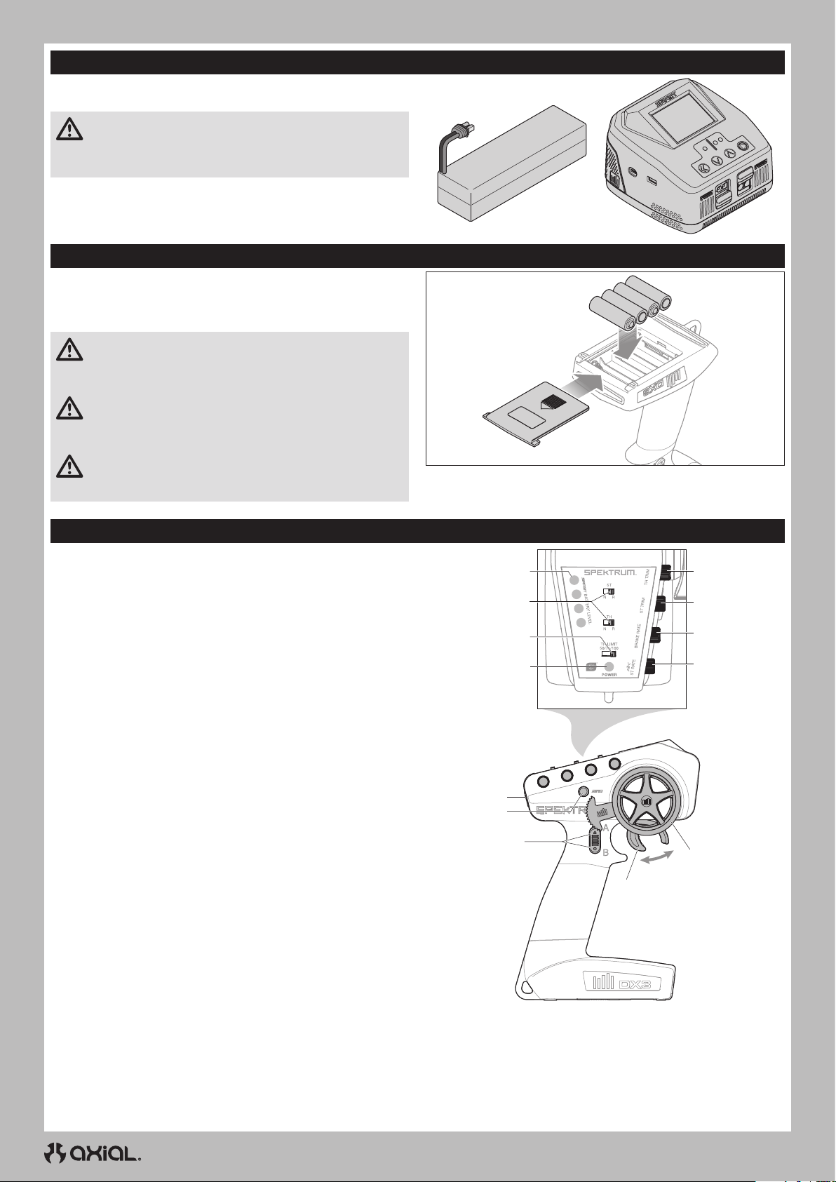
DE
LADEN DES FAHRZEUG-AKKUS
Befolgen Sie die Anweisungen des Herstellers Ihres Ladegeräts, um
den Fahrzeug-Akku ordnungsgemäß zu laden.
ACHTUNG: Verwenden Sie nur Ladegeräte, die für das Laden
des gewählten Akkutyps ausgelegt sind. Die Verwendung eines
falschen Ladegeräts oder eine falsche Ladeeinstellung kann dazu
führen, dass der Akku brennt oder explodiert.
EINSETZEN DER SENDERBATTEREIEN
Für den Betrieb sind 4 AA Batterien erforderlich.
1. Nehmen Sie die Batterieklappe vom Sender ab.
2. Setzen Sie die Batterien wie abgebildet ein.
3. Setzen Sie die Batterieklappe wieder auf.
ACHTUNG: Entfernen Sie niemals Batterien aus dem
Sender, während das Modell eingeschaltet ist. Ein Verlust der
Kontrolle über das Modell, Schäden oder Verletzungen können
auftreten.
ACHTUNG: Wenn Sie wiederaufladbare Akkus verwenden
dürfen Sie nur diese laden. Das Laden von nicht aufladbaren
Batterien könnte diese zur Explosion bringen, was Sach- und
Personenschäden zur Folge haben könnte.
ACHTUNG: Es besteht Explosionsrisiko wenn die Akkus
durch einen falschen Typ ersetzt werden. Entsorgen Sie
verbrauchte Batterien den Vorschriften entsprechend.
FUNKTIONEN DES SENDERS
Wählbarer Antrieb Rechts hinten (ASD-Funktion)
A.
Wählbarer Antrieb Links hinten (ASD-Funktion)
B.
THROTTLE/BRAKE (GAS/BREMSE)
C.
STEUERRAD
D.
STEUERRATE
E.
Passt den Endpunkt der Steuerung an
BRAKE RATE
F.
Adjusts the braking end point.
STEUERTRIMMUNG
G.
Zur Anpassung des Steuermittelpunkts. Normalerweise wird die Steuertrimmung
solange eingestellt, bis das Fahrzeug gerade in der Spur läuft.
GASTRIMMUNG
H.
Zur Anpassung des Gasnullpunktes
LADEZUSTANDSANZEIGE SMART-AKKU
I.
UMKEHREN DER SERVOLAUFRICHTUNG
J.
Um den Kanal für die Gaszufuhr (TH) oder die Steuerung (ST) umzukehren,
die Position des entsprechenden Schalters umschalten – „N“ steht für
normal, „R“ für Umkehren.
BEGRENZUNG GASZUFUHR
K.
Begrenzt die Gaszufuhr auf 50/75/100%
Wählen Sie 50oder 75% für Fahrer mit weniger Erfahrung oder wenn das
Fahrzeug in einem kleinen Gebiet gefahren wird.
ANZEIGE-LEUCHTEN
L.
• Durchgängig rot: Zeigt die Funkverbindung und die ausreichende
Akkuladung an
• Rot blinkend: Zeigt an, dass die Akku-Spannung kritisch niedrig ist.
Akkus ersetzen
EIN-/AUSSCHALTER
M.
BINDUNGSSCHALTER
N.
I
J
K
L
M
N
A/B
C
H
G
F
E
D
20
Page 21
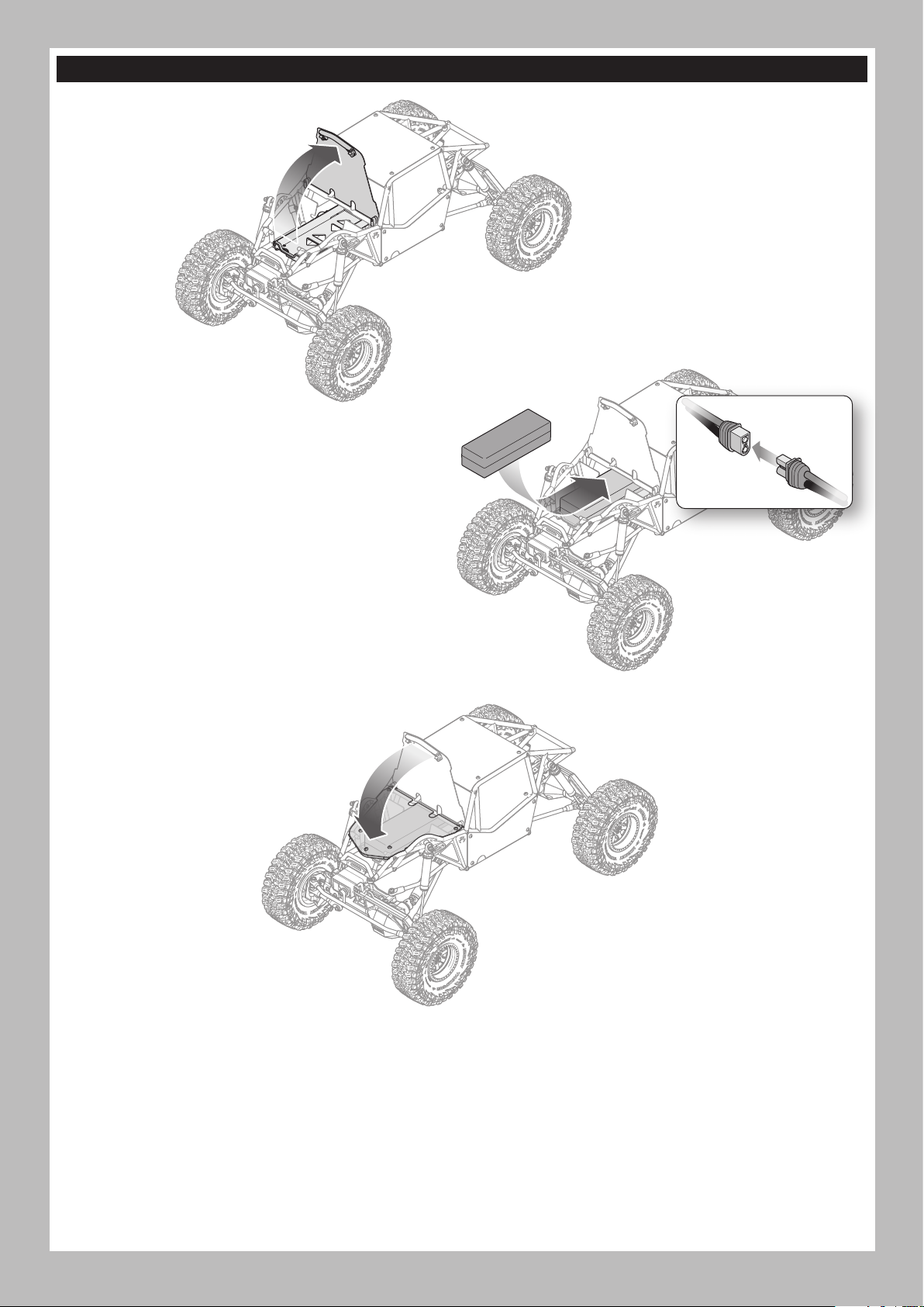
DEN FAHRZEUG-AKKU EINSETZEN
1. Ziehen Sie unter der vorderen Stange der Motorhaube
nach oben, um an das Akkufach zu gelangen.
2. Setzen Sie den empfohlenen Fahrzeugakku mit den Stromkabeln
nach vorne in das Akkufach ein.
3. Die Akku-Kabel am Anschluss des Geschwindigkeitsreglers mit
der richtigen Polarität anschließen.
4. Den Akku mit den installierten Klettbändern im Akkufach sichern.
TIPP: Verhindern Sie, dass sich der Anschluss des Akkukabels
bewegt, indem Sie das Klettband über das Stromkabel ziehen.
DE
5. Drücken Sie die Vorderseite der Klappe nach unten, bis sie an
beiden vorderen Ecken sicher einrastet.
21
Page 22
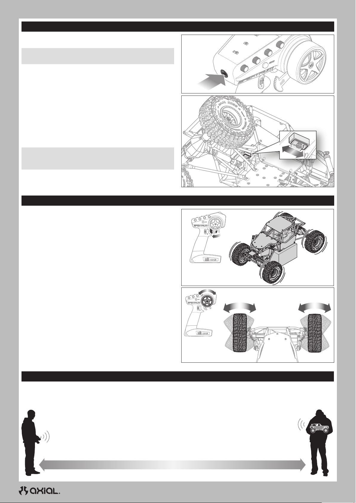
DE
EIN- UND AUSSCHALTEN
EINSCHALTEN
1. Den Sender einschalten.
HINWEIS: Schalten Sie immer den Sender ein, bevor Sie das
Fahrzeug einschalten.
2. Schalten Sie das Fahrzeug ein, indem Sie den Schalter am
Fahrzeug nach hinten schieben.
AUSSCHALTEN
1. Schalten Sie das Fahrzeug aus, indem Sie den Schalter zur
Vorderseite des Fahrzeugs schieben.
HINWEIS: Vor dem Ausschalten des Senders immer das Fahrzeug
ausschalten. Wird der Sender zuerst ausgeschaltet, kann dies zum
Verlust der Steuerung führen.
2. Den Sender ausschalten.
3. Den Akku vom Geschwindigkeitsregler trennen.
4. Entfernen Sie zum Laden oder Lagern den Akku aus dem Fahrzeug.
Power
KONTROLLTEST
Einen Lenktest durchführen, während die Räder des Fahrzeugs den
Boden nicht berühren.
• Damit die Räder vorwärts rollen, den Hebel betätigen.
WICHTIG: Das serienmäßige Getriebe gibt der Hinterachse
des Fahrzeugs „Untersteuerung“. Die Hinterräder drehen sich
langsamer als die Vorderräder.
• Um die Räder umzukehren, warten bis sie stoppen und betätigen Sie
dann den Hebel.
• Wenn sich die Räder nach dem Einschalten des Fahrzeugs drehen,
stellen Sie den TH TRIM-Regler so ein, dass sie sich nicht mehr ohne
Gaseingabe drehen.
• Drehen Sie das Lenkrad des Senders nach links und rechts und
prüfen Sie, ob sich die Räder des Fahrzeugs in die vom Sender
vorgegebene Richtung drehen.
Stellen Sie das Fahrzeug auf den Boden und geben Sie langsam Gas:
• Wenn das Fahrzeug vorwärts rollt, muss es ohne Lenkeinwirkung
auf einer geraden Linie bleiben. Ist dies nicht der Fall, verstellen Sie
den ST TRIM-Knopf nach links oder rechts, bis das Fahrzeug auf
einer geraden Linie bleibt, ohne mit dem Lenkrad korrigiert werden
zu müssen.
REICHWEITENTEST FÜR DAS FUNKSYSTEM DURCHFÜHREN
Das Funksystem sollte vor dem Betrieb des Fahrzeugs überprüft werden, um einen ordnungsgemäßen Betrieb und eine
ausreichende Reichweite zu gewährleisten.
1. Den Sender einschalten.
2. Den Akku an das Fahrzeug anschließen.
3. Bitten Sie jemanden das Fahrzeug zu halten, damit Sie Hände und lose Kleidung von beweglichen Teilen fernhalten können.
4. Bewegen Sie sich so weit vom Fahrzeug weg, bis Sie den maximal geplanten Betriebsabstand zum Fahrzeug
erreicht haben.
5. Drehen Sie das Steuerrad von einer Seite zur anderen und betätigen Sie die Gaszufuhr, sowohl vorwärts als auch
rückwärts, und achten Sie darauf, ob Sie irgendein unregelmäßiges Verhalten bemerken.
6. Wenn ein unregelmäßiges Verhalten auftritt, dürfen Sie das Fahrzeug NICHT zum Einsatz bringen. Wenden Sie sich
in diesem Fall an den Kundendienst.
22
Page 23
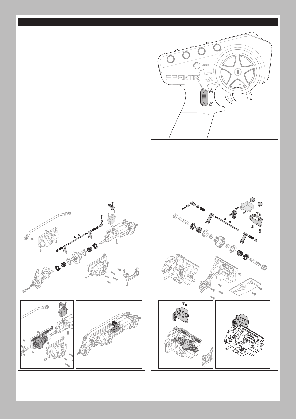
AXIAL SELECTABLE DRIVE (ASD)
An der Hinterachse des Fahrzeugs ist der Axial Selectable Drive (ASD)
bereits vorinstalliert. ASD ermöglicht es dem Fahrer, entweder das
linke oder das rechte Hinterrad zu blockieren, so dass das Fahrzeug
durch Schwenken um das „blockierte“ Rad sehr enge Kurvenradien
fahren kann.
ASD aktivieren:
1. Halten Sie entweder die Taste A oder B gedrückt.
• Mit A rastet die linke Radsperre ein
• Mit B rastet die rechte Radsperre ein
2. Drehen Sie das Lenkrad und geben Sie langsam oder stoßweise
Gas, um das Fahrzeug um das blockierte Rad zu drehen.
TIPP: Durch Drehen des Lenkrads in Richtung des blockierten
Rads wird eine enge Kurve in diese Richtung erzeugt.
Wird das Lenkrad auf der Gegenseite des blockierten Rades
gedreht, bewirkt dies ein langsames Gleiten vom blockierten Rad
weg.
3. Lassen Sie den A- oder B-Knopf los und geben Sie Gas, um das
Rad zu „entriegeln“.
TIPP: Es kann notwendig sein, den Rückwärtsgang leicht zu
betätigen, um ASD zu lösen.
ZUSÄTZLICHE ASD-FUNKTIONEN (OPTIONAL)
Mit dem zusätzlichen Kauf eines Servos und des ASD-Teile-Sets: AXP8
(AXI-2191), Axial Selectable Drive kann entweder an der Vorderachse,
am Getriebe oder mit dem Kauf von zwei Sets und Servos an
Vorderachse und Getriebe hinzugefügt werden.
WICHTIG: Die Steuerung der zusätzlichen optionalen Funktionen
erfordert einen Sender mit mehr als drei Kanälen, wie z.B. den
Spektrum™ DX6 Rugged DSMR-Sender mit 6 Kanälen (SPMR6215).
DE
EINBAU DES ASD AN DER VORDERACHSE (OPTIONAL)
So aktivieren Sie das ASD vorn links und rechts
Servo nicht enthalten (SPMSSX117AX empfohlen)
EINBAU DES ASD AM GETRIEBE (OPTIONAL)
So aktivieren Sie das ASD vorn und hinten
Servo nicht enthalten (SPMSSX117AX empfohlen)
23
Page 24
DE
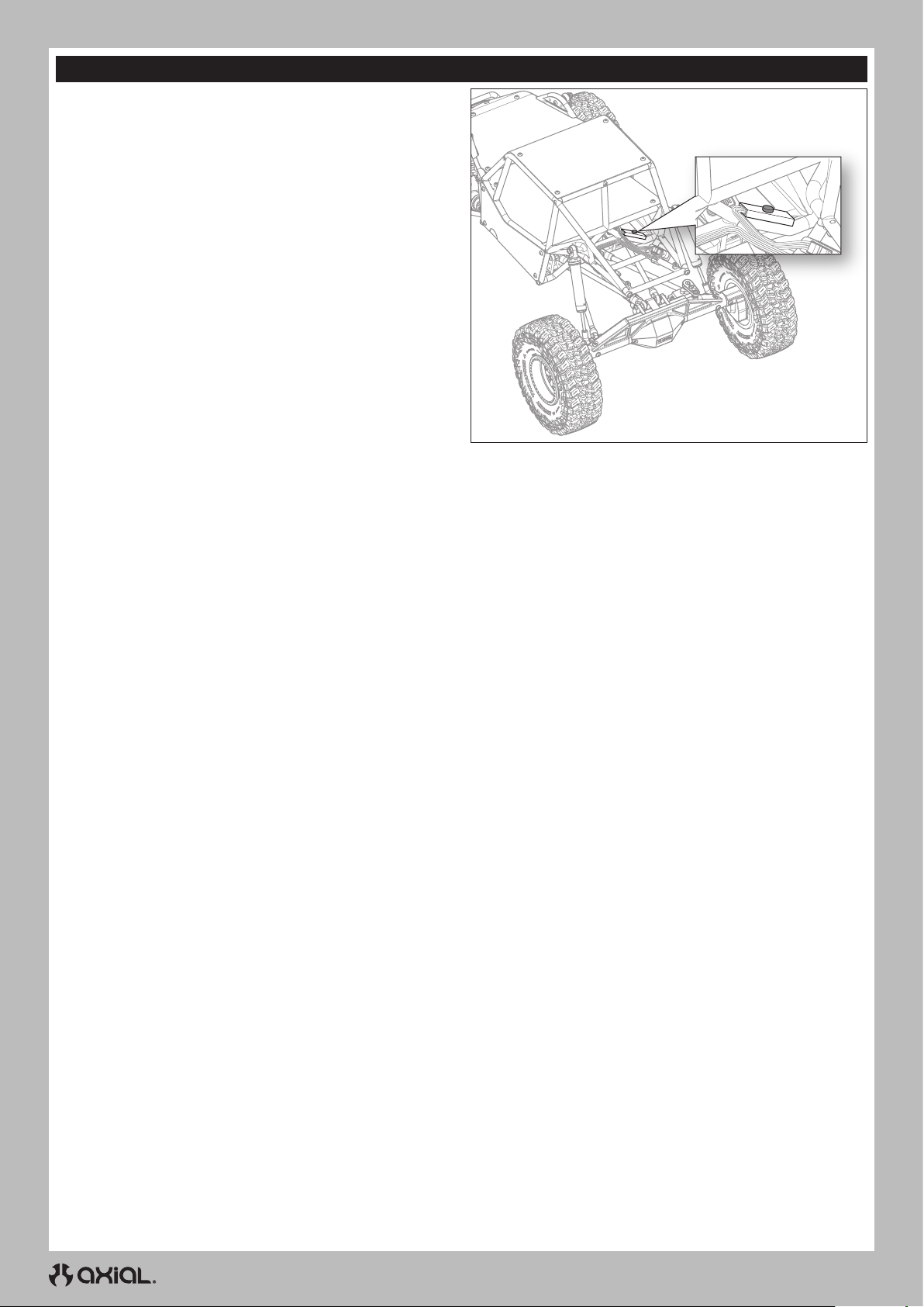
LED-GELÄNDESCHEINWERFER
Das Fahrzeug wird mit farblich wählbaren RGB-LEDGeländescheinwerfern geliefert.
Bedienung der Beleuchtung:
1. Das Fahrzeug einschalten.
2. Drücken Sie die Lichtsteuerungstaste, die sich wie abgebildet auf
der Rückseite des mittleren Überrollkäfigs befindet. Die LEDLeuchten leuchten beim ersten Drücken rot auf.
3. Durch wiederholtes Drücken der Steuertaste können Sie zwischen
den sieben verfügbaren Farben wechseln, bis die gewünschte
Farbe angezeigt wird.
4. Schalten Sie die Beleuchtung aus, indem Sie mit der Steuertaste
durch die Farben schalten, bis die Beleuchtung ausgeschaltet ist.
LED-SEQUENZ:
1. Rot
2. Grün
3. Blau
4. Gelb
5. Lila
6. Blaugrün
7. Weiß
8. Aus
24
Page 25
FAHRZEUGWARTUNG
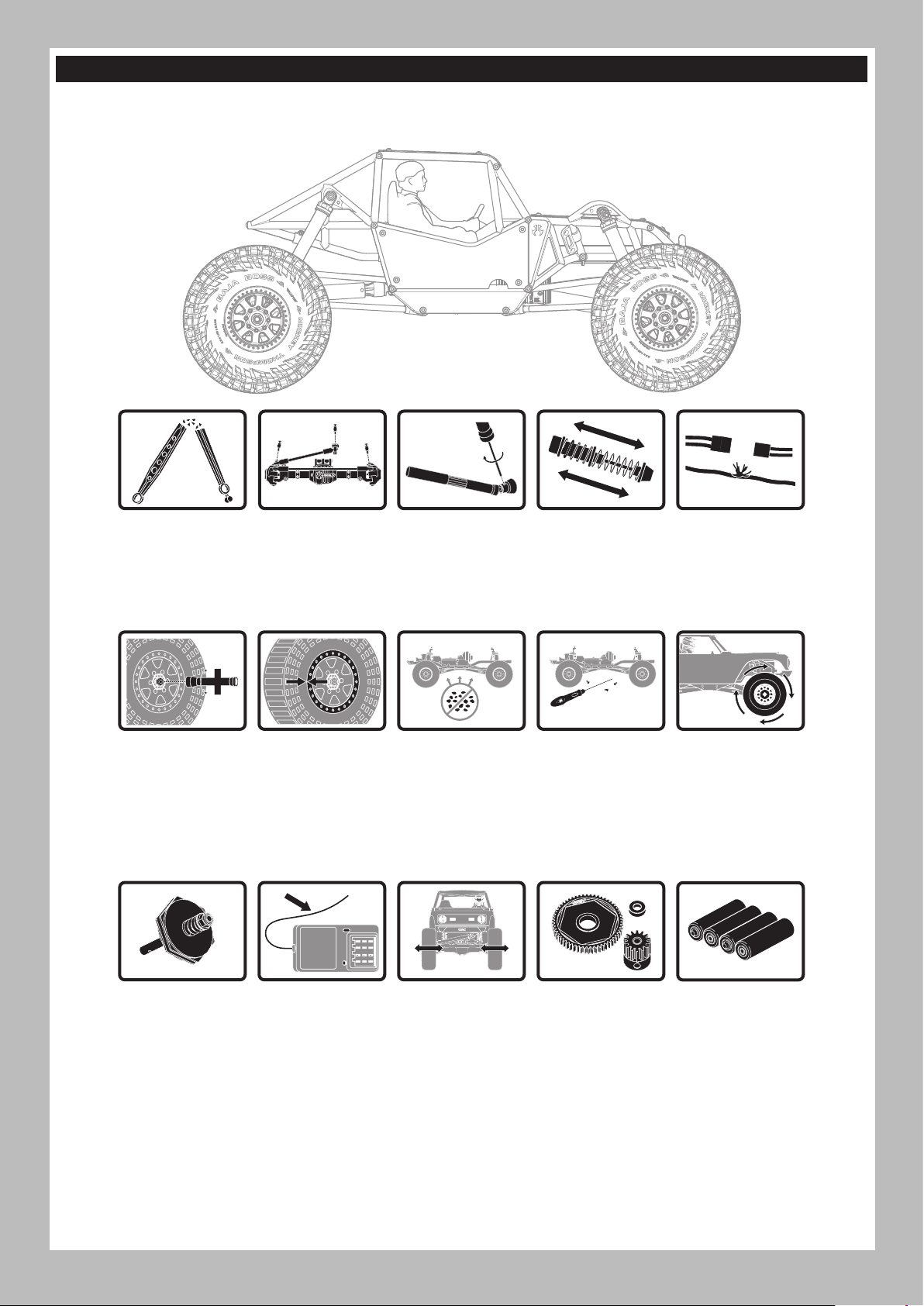
Genau wie bei einem richtigen Auto oder LKW muss Ihr RC-Fahrzeug regelmäßig gewartet werden, um eine hohe Leistungsfähigkeit zu
gewährleisten. Vorbeugende Wartung hilft auch, unnötige Ausfälle zu vermeiden, die zu kostspieligen Reparaturen führen können. Nachfolgend
finden Sie einige Vorschläge zur ordnungsgemäßen Wartung Ihres Fahrzeugs.
DE
Ersetzen Sie alle
erkennbaren
gebogenen oder
gebrochenen Teile
Die Radmuttern auf
festen Sitz prüfen
Überprüfen Sie
den Verschleiß der
Kugelgelenke an den
Lenkgliedern und
Aufhängungen (ggf.
austauschen)
Sicherstellen, dass
die Radflanschen
noch fest über den
gesamten Umfang der
Felge verbunden sind
Die Einstellung
der Schrauben für
die Antriebswelle
prüfen und ggf.
Gewindesicherung
anbringen
Die Karosserie frei
von Schmutz und
Ablagerungen halten
Die Stoßdämpfer
auf reibungslosen,
gedämpften Betrieb
prüfen
Die Karosserie auf
lose Schrauben
überprüfen,
insbesondere die
Schrauben für
Achsschenkel,
C-Naben und
Achsausgänge
Überprüfen, ob lose
Verbindungen oder
ausgefranste Kabel
vorhanden sind
Überprüfen des
Antriebsstrangs auf
einen reibungslosen,
bindungsfreien Betrieb
Ggf. die Gleitkupplung
auf ihre einwandfreie
Funktion überprüfen
Die Empfängerantenne
auf Beschädigungen
prüfen
Die Lenkfunktion auf
eine mögliche Bindung
überprüfen
25
Überprüfen des
Stirnrads und der
Ritzelräder auf
Beschädigungen
Die Sender-Akkus
ersetzen, wenn
der Sender dies,
wie im Abschnitt
Senderfunktionen
beschrieben, anzeigt
Page 26
DE
BINDEN
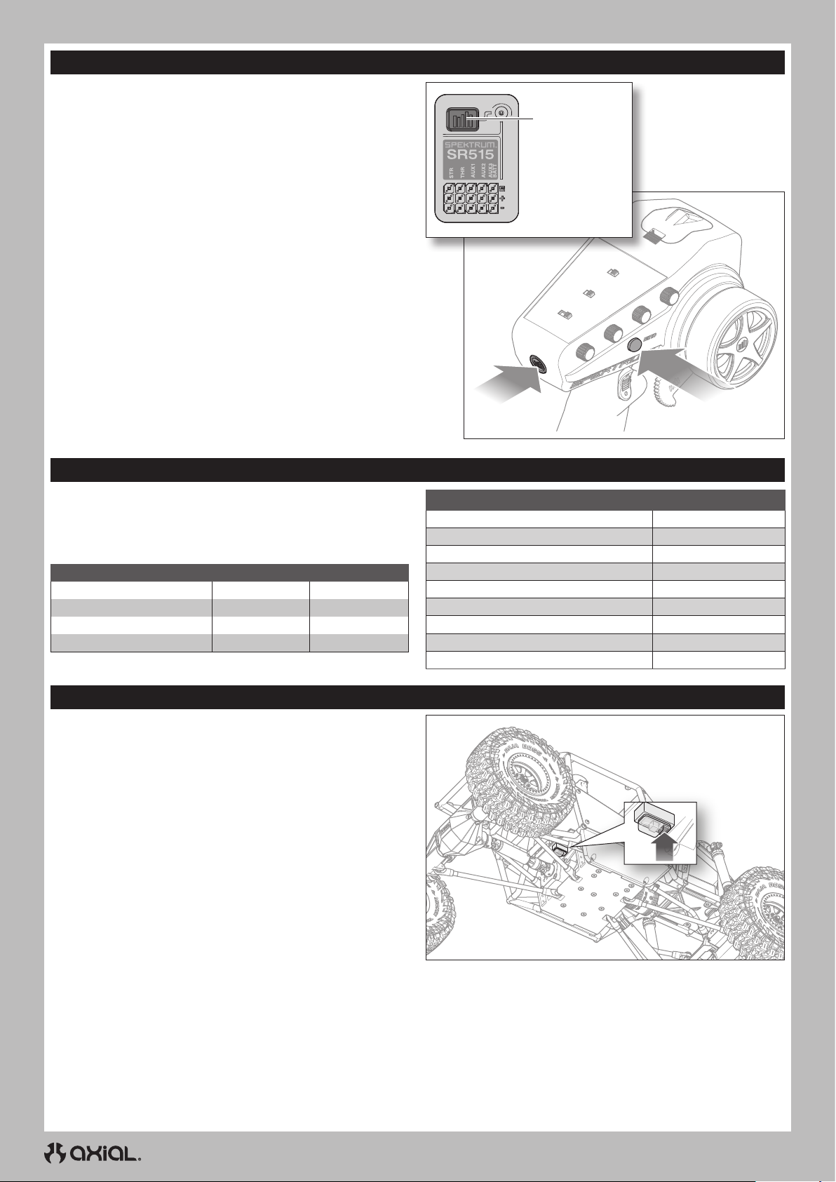
Das Binden ist der Vorgang, durch den der Empfänger darauf
programmiert wird, den GUID-Code (Globally Unique Identifier) eines
einzelnen Senders zu erkennen. Der Sender und der Empfänger sind
werksseitig gebunden. Muss eine erneute Bindung durchgeführt
werden, so ist die nachfolgende Anleitung zu befolgen.
1. Ein voll aufgeladenes Akkupack mit dem Geschwindigkeitsregler/
Empfänger verbinden.
2. Den Bindungsschalter am Sender gedrückt halten.
3. Den Empfänger einschalten. Die rote LED blinkt und zeigt an, dass
sich der Empfänger im Bindungsmodus befindet.
4. Den Bindungsschalter loslassen.
5. Der Gasauslöser befindet sich in Neutral, den Bindungsschalter
des Senders während des Einschaltens gedrückt halten, um den
Sender in den Bindungsmodus zu versetzen.
WICHTIG: Gas sollte auf Neutral stehen, um Failsafe
einzurichten.
6. Der Bindungsvorgang ist abgeschlossen, wenn die grüne LED auf
dem Empfänger durchgängig leuchtet.
Ein erneutes Binden muss durchgeführt werden, wenn andere
Failsafe-Positionen erforderlich sind, z.B. wenn Gas oder Steuerung
umgekehrt wurden.
Bindungsschalter
BindungsschalterEin-/Ausschalter
LED-ANZEIGE UND MOTORSIGNALE
Nach dem Einschalten des Geschwindigkeitsreglers blinkt die rote
LED und der Motor gibt eine Reihe von Pieptönen aus, um den
Status anzuzeigen. Zuerst wird der Akkumodus angezeigt, dann die
Einstellung der Schleppbremse und anschließend wird angezeigt, dass
das Gerät betriebsbereit ist.
Funktion LED-Status Motorsignal
Ni-MH/Ni-CD-Akku 1-maliges Blinken 1 kurzer Piepton
2S Li-Po-Akku 2-maliges Blinken 2 kurze Pieptöne
3S Li-Po-Akku 3-maliges Blinken 3 kurze Pieptöne
Geschwindigkeitsregler bereit 1 langes Blinken 1 langer Piepton
Stopp AUS
Gedrosselte Vorwärtsbewegung Blinkt
Gedrosselte Rückwärtsbewegung Blinkt
Teilbremsung Blinkt
Schwacher Akku Blinkt
Überhitzung Blinkt
Während des Betriebs LED-Status
Vollgas Durchgängig
Vollgas Durchgängig
Vollbremsung Durchgängig
KALIBRIERUNG VON GESCHWINDIGKEITSREGLER UND SENDER
Es ist wichtig, den Geschwindigkeitsregler auf den Sender zu
kalibrieren, damit der Geschwindigkeitsregler mit dem Gasbereich
Ihres Senders übereinstimmt. Wenn Sie die Geschwindigkeitsregler
nicht auf Ihr Funksystem kalibrieren, funktioniert die
Geschwindigkeitsregler nicht korrekt. Stellen Sie den Fail Safe an
Ihrem Funkgerät in eine neutrale Position, um sicherzustellen, dass der
Motor im Falle eines Signalverlusts anhält.
1. Den Sender einschalten.
2. Stellen Sie den Gasbegrenzungsschalter auf 100 %, und zentrieren
Sie die Gastrimmung, bevor Sie mit der Kalibrierung fortfahren.
3. Einen Akku an den Geschwindigkeitsregler anschließen.
4. Halten Sie die Programmiertaste im Schaltbereich gedrückt,
während Sie den Geschwindigkeitsregler einschalten.
Die rote LED am Geschwindigkeitsregler blinkt und der Motor gibt
einen Piepton aus.
5. Die Programmiertaste innerhalb von 3 Sekunden loslassen.
WICHTIG: Wenn Sie die Programmiertaste nicht innerhalb von 3
Sekunden loslassen, wechselt der Geschwindigkeitsregler in den
Programmiermodus. Wenn der Geschwindigkeitsregler in den
Programmiermodus wechselt, schalten Sie das Fahrzeug aus und
kehren Sie zu Schritt 4 zurück.
6. Wenn sich der Gaszug und die Trimmung in der Neutralstellung
befinden, die Programmiertaste drücken und loslassen. Die rote
LED blinkt einmal und der Motor gibt 1 Ton aus.
TIPP: Die Pieptöne des Motors können schwer zu hören
sein. Verwenden Sie den LED-Status, um die Einstellungen zu
überprüfen.
7. Den Gashebel in Vollgas-Stellung bewegen. Programmiertaste
drücken und loslassen. Die rote LED blinkt zweimal und der Motor
gibt 2 Töne aus.
8. Den Gashebel ganz nach hinten ziehen. Programmiertaste
drücken und loslassen. Die rote LED blinkt dreimal und der Motor
gibt 3 Töne aus.
9. Schalten Sie das System mit dem EIN/AUS-Schalter AUS.
10. Schalten Sie das System mit dem EIN/AUS-Schalter EIN. Das
System ist nun betriebsbereit
26
Page 27
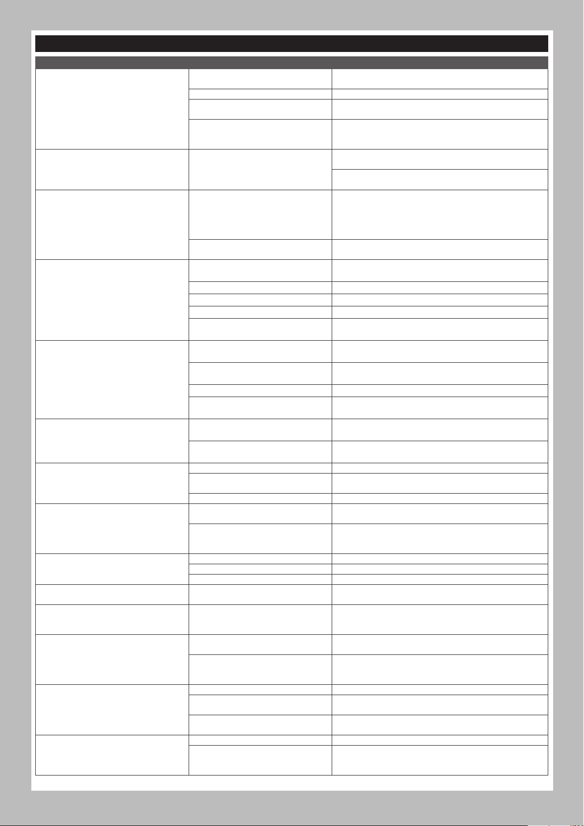
PROBLEMLÖSUNG
DE
PROBLEM
Das System verbindet sich nicht
Der Empfänger schaltet sich in Failsafe,
obwohl er sich in geringer Entfernung zum
Sender befindet
Der Empfänger reagiert während des
Betriebs nicht mehr
Fahrzeug bewegt sich nicht
Schaden an/Verlust der
Fahrzeugsteuerung
Steuer- und/oder Gaszufuhrfunktion ist
vertauscht
Geschwindigkeitsregler EIN – Keine
Motorfunktion, hörbare Töne oder LED
Motor – Stoppt und LED blinkt
Motor – Beschleunigt ungleichmäßig
Motor – Reagiert nicht kontinuierlich auf
Gas
Motor – Wird langsamer, stoppt aber
nicht–
Servolenkung – Funktioniert; Motor nicht
in Betrieb
Steuerung/Motor – Funktioniert nicht
Fahrzeug – Funktioniert nicht auf voller
Geschwindigkeit
MÖGLICHE URSACHE LÖSUNG
Der Sender und der Empfänger sind zu
nah aneinander
Sie sind in der Nähe von Metallobjekten In einen Bereich mit weniger Metall gehen
Der Empfänger ist an einen anderen
Modellspeicher gebunden
Der Sender wurde in den
Bindungsmodus versetzt und ist nicht
länger mit dem Empfänger gebunden
Auf Schäden an der Empfängerantenne
prüfen
Niedrige Empfänger-Akkuspannung.
Ist die Akku-Spannung niedrig, kann
sie kurzzeitig unter 3,5V fallen und so
einen Spannungsabfall im Empfänger
verursachen, sich dann erneut verbinden
Lose oder beschädigte Kabel oder
Stecker zwischen Akku und Empfänger
Die Akkus sind nicht richtig in den
Sender eingesetzt
Schwacher oder kein Akku im Fahrzeug Einsetzen eines neu aufgeladenen Fahrzeug-Akkus
Beschädigter Motor Motor ersetzen
Ausgefranste oder gebrochene Kabel Jedes beschädigte Kabel ersetzen
Geschwindigkeitsregler wird durch
Hitzeschutzschaltung abgeschaltet
Unsachgemäße Positionierung der
Antenne
Schwacher oder kein Akku im Sender
oder Fahrzeug
Neutral- oder Trimmposition ist falsch Steuertrimmung ausrichten
Empfänger und/oder Akku nicht richtig
angeschlossen
Der Servo-Verfahrweg ist umgekehrt am
Sender
Motorkabel sind nicht ordnungsgemäß
verbunden
Akku-/Verbindungsproblem Akku aufladen/ersetzen. Alle Verbindungen sichern
Beschädigter Geschwindigkeitsregler/
Schalter
Beschädigter Motor Reparieren/ersetzen
Verpolungsschutz
Überhitzungsschutz
Akku-Problem Beschädigte Kabel reparieren/Akkus ersetzen
Falsche Getriebeübersetzung Getriebe anpassen/ersetzen
Verschlissener oder beschädigter Motor Motor reparieren/ersetzen
Geschwindigkeitsregler/Motor
beschädigt
Falsche Kalibrierung von Sender/
Geschwindigkeitsregler
Beschädigter Motor
Falsche Kalibrierung von Sender/
Geschwindigkeitsregler
Niedrige Akkuspannung Aufladen/ersetzen
Falscher Modellspeicher auf Sender
ausgewählt
Empfänger nicht am Sender gebunden
Akku-Problem Aufladen/ersetzen
Falsche Kalibrierung von Sender/
Geschwindigkeitsregler
Den Sender 2,44 bis 3,66m vom Empfänger entfernt
verschieben
Sicherstellen, dass der korrekte Modellspeicher im Sender
aktiv ist
Den Sender und Empfänger erneut binden und dann erneut
kalibrieren
Sicherstellen, dass die Empfängerantenne geschützt und so
hoch wie praktikabel positioniert ist
Empfänger ersetzen oder den Horizon-Kundendienst
kontaktieren
Den Akku von Empfänger oder Fahrzeug aufladen. Die
Spektrum-Empfänger erfordern für den Betrieb mindestens
3,5V
Die Kabel und Verbindungen zwischen Akku und Empfänger
überprüfen. Kabel und/oder Stecker reparieren oder ersetzen
Sicherstellen, dass die Sender-Akkus richtig eingesetzt sind
Den Geschwindigkeitsregler vollständig abkühlen lassen
Sicherstellen, dass die Senderantenne nicht blockiert ist und
die Empfängerantenne richtig positioniert ist
Einsetzen eines neu aufgeladenen Fahrzeug- oder SenderAkkus
Alle Empfänger- und Akku-Verbindungen überprüfen
Den Servoumkehrschalter des Senders in die richtige
Position bringen
Überprüfen aller Motorkabel auf korrekte Polarität und
sichere Verbindung
Geschwindigkeitsregler-Schalter/Geschwindigkeitsregler
reparieren/ersetzen
Wenn die Geschwindigkeitsregler-LED blinkt, Akku laden/
ersetzen
Wenn die grüne LED blinkt, den Geschwindigkeitsregler/
Motor abkühlen lassen, Konfiguration oder Übersetzung
ändern, damit Überhitzung vermieden wird
Verkabelung oder Motor/Geschwindigkeitsregler reparieren/
ersetzen
Gasweg/andere Gaseinstellungen auf Sender/
Geschwindigkeitsregler anpassen. Kalibrierungsverfahren
des Geschwindigkeitsreglers wiederholen
Motor unabhängig vom Fahrzeugsystem testen, bei Bedarf
Motor reparieren/ersetzen
Gasweg/andere Gaseinstellungen auf Sender/
Geschwindigkeitsregler anpassen. Kalibrierungsverfahren
des Geschwindigkeitsreglers wiederholen
Korrekte Modelleinstellungen auf dem Sender wählen, siehe
Sender- und/oder Empfänger-Handbuch
Sender am Empfänger binden, siehe Sender- und/oder
Empfänger-Handbuch
Gasweg/andere Gaseinstellungen auf Sender/
Geschwindigkeitsregler anpassen. Kalibrierungsverfahren
des Geschwindigkeitsreglers wiederholen
27
Page 28

DE
EINGESCHRÄNKTE GARANTIE
Warnung
Ein ferngesteuertes Modell ist kein Spielzeug. Es kann, wenn es
falsch eingesetzt wird, zu erheblichen Verletzungen bei Lebewesen
und Beschädigungen an Sachgütern führen. Betreiben Sie Ihr
RC-Modell nur auf freien Plätzen und beachten Sie alle Hinweise der
Bedienungsanleitung des Modells wie auch der Fernsteuerung.
Garantiezeitraum
Exklusive Garantie Horizon Hobby LLC (Horizon) garantiert, dass
dasgekaufte Produkt frei von Material- und Montagefehlern ist.
Der Garantiezeitraum entspricht den gesetzlichen Bestimmung des
Landes, in dem das Produkt erworben wurde. In Deutschland beträgt
der Garantiezeitraum 6 Monate und der Gewährleistungszeitraum 18
Monate nach dem Garantiezeitraum.
Einschränkungen der Garantie
(a) Die Garantie wird nur dem Erstkäufer (Käufer) gewährt und kann
nicht übertragen werden. Der Anspruch des Käufers besteht
in der Reparatur oder dem Tausch im Rahmen dieser Garantie.
Die Garantie erstreckt sich ausschließlich auf Produkte, die
bei einem autorisierten Horizon Händler erworben wurden.
Verkäufe an dritte werden von dieser Garantie nicht gedeckt.
Garantieansprüche werden nur angenommen, wenn ein
gültiger Kaufnachweis erbracht wird. Horizon behält sich das
Recht vor, diese Garantiebestimmungen ohne Ankündigung
zu ändern oder modifizieren und widerruft dann bestehende
Garantiebestimmungen.
(b) Horizon übernimmt keine Garantie für die Verkaufbarkeit des
Produktes, die Fähigkeiten und die Fitness des Verbrauchers
für einen bestimmten Einsatzzweck des Produktes. Der Käufer
allein ist dafür verantwortlich, zu prüfen, ob das Produkt seinen
Fähigkeiten und dem vorgesehenen Einsatzzweck entspricht.
(c) Ansprüche des Käufers ¬ Es liegt ausschließlich im Ermessen
von Horizon, ob das Produkt, bei dem ein Garantiefall festgestellt
wurde, repariert oder ausgetauscht wird. Dies sind die exklusiven
Ansprüche des Käufers, wenn ein Defekt festgestellt wird.
Horizon behält sich vor, alle eingesetzten Komponenten zu prüfen,
die in den Garantiefall einbezogen werden können. Die Entscheidung
zur Reparatur oder zum Austausch liegt nur bei Horizon. Die
Garantie schließt kosmetische Defekte oder Defekte, hervorgerufen
durch höhere Gewalt, falsche Behandlung des Produktes, falscher
Einsatz des Produktes, kommerziellen Einsatz oder Modifikationen
irgendwelcher Art aus.
Die Garantie schließt Schäden, die durch falschen Einbau, falsche
Handhabung, Unfälle, Betrieb, Service oder Reparaturversuche, die
nicht von Horizon ausgeführt wurden aus.
Ausgeschlossen sind auch Fälle die bedingt durch (vii) eine Nutzung
sind, die gegen geltendes Recht, Gesetze oder Regularien verstoßen
haben. Rücksendungen durch den Käufer direkt an Horizon oder eine
seiner Landesvertretung bedürfen der Schriftform.
Schadensbeschränkung
Horizon ist nicht für direkte oder indirekte Folgeschäden,
Einkommensausfälle oder kommerzielle Verluste, die in irgendeinem
Zusammenhang mit dem Produkt stehen verantwortlich, unabhängig
ab ein Anspruch im Zusammenhang mit einem Vertrag, der Garantie
oder der Gewährleistung erhoben werden. Horizon wird darüber
hinaus keine Ansprüche aus einem Garantiefall akzeptieren, die über
den individuellen Wert des Produktes hinaus gehen. Horizon hat
keinen Einfluss auf den Einbau, die Verwendung oder die Wartung
des Produktes oder etwaiger Produktkombinationen, die vom Käufer
gewählt werden. Horizon übernimmt keine Garantie und akzeptiert
keine Ansprüche für in der folge auftretende Verletzungen oder
Beschädigungen. Mit der Verwendung und dem Einbau des Produktes
akzeptiert der Käufer alle aufgeführten Garantiebestimmungen ohne
Einschränkungen und Vorbehalte.
Wenn Sie als Käufer nicht bereit sind, diese Bestimmungen im
Zusammenhang mit der Benutzung des Produktes zu akzeptieren,
werden Sie gebeten, dass Produkt in unbenutztem Zustand in der
Originalverpackung vollständig bei dem Verkäufer zurückzugeben.
Sicherheitshinweise
Dieses ist ein hochwertiges Hobby Produkt und kein Spielzeug. Es
muss mit Vorsicht und Umsicht eingesetzt werden und erfordert
einige mechanische wie auch mentale Fähigkeiten. Ein Versagen,
das Produkt sicher und umsichtig zu betreiben kann zu Verletzungen
von Lebewesen und Sachbeschädigungen erheblichen Ausmaßes
führen. Dieses Produkt ist nicht für den Gebrauch durch Kinder ohne
die Aufsicht eines Erziehungsberechtigten vorgesehen. Die Anleitung
enthält Sicherheitshinweise und Vorschriften sowie Hinweise für
die Wartung und den Betrieb des Produktes. Es ist unabdingbar,
diese Hinweise vor der ersten Inbetriebnahme zu lesen und zu
verstehen. Nur so kann der falsche Umgang verhindert und Unfälle mit
Verletzungen und Beschädigungen vermieden werden.
Fragen, Hilfe und Reparaturen
Ihr lokaler Fachhändler und die Verkaufstelle können eine
Garantiebeurteilung ohne Rücksprache mit Horizon nicht durchführen.
Dies gilt auch für Garantiereparaturen. Deshalb kontaktieren Sie in
einem solchen Fall den Händler, der sich mit Horizon kurz schließen
wird, um eine sachgerechte Entscheidung zu fällen, die Ihnen
schnellst möglich hilft.
Wartung und Reparatur
Muss Ihr Produkt gewartet oder repariert werden, wenden Sie sich
entweder an Ihren Fachhändler oder direkt an Horizon.
Rücksendungen / Reparaturen werden nur mit einer von Horizon
vergebenen RMA Nummer bearbeitet. Diese Nummer erhalten Sie
oder ihr Fachhändler vom technischen Service. Mehr Informationen
dazu erhalten Sie im Serviceportal unter www. Horizonhobby.de oder
telefonisch bei dem technischen Service von Horizon.
Packen Sie das Produkt sorgfältig ein. Beachten Sie, dass der
Originalkarton in der Regel nicht ausreicht, um beim Versand nicht
beschädigt zu werden. Verwenden Sie einen Paketdienstleister mit
einer Tracking Funktion und Versicherung, da Horizon bis zur Annahme
keine Verantwortung für den Versand des Produktes übernimmt.
Bitte legen Sie dem Produkt einen Kaufbeleg bei, sowie eine
ausführliche Fehlerbeschreibung und eine Liste aller eingesendeten
Einzelkomponenten. Weiterhin benötigen wir die vollständige
Garantie und Reparaturen
Garantieanfragen werden nur bearbeitet, wenn ein Originalkaufbeleg
von einem autorisierten Fachhändler beiliegt, aus dem der Käufer und
das Kaufdatum hervorgeht. Sollte sich ein Garantiefall bestätigen wird
das Produkt repariert oder ersetzt. Diese Entscheidung obliegt einzig
Horizon Hobby.
Kostenpflichtige Reparaturen
Liegt eine kostenpflichtige Reparatur vor, erstellen wir einen
Kostenvoranschlag, den wir Ihrem Händler übermitteln. Die Reparatur
wird erst vorgenommen, wenn wir die Freigabe des Händlers erhalten.
Der Preis für die Reparatur ist bei Ihrem Händler zu entrichten.
Bei kostenpflichtigen Reparaturen werden mindestens 30 Minuten
Werkstattzeit und die Rückversandkosten in Rechnung gestellt. Sollten
wir nach 90 Tagen keine Einverständniserklärung zur Reparatur
vorliegen haben, behalten wir uns vor, das Produkt zu vernichten oder
anderweitig zu verwerten.
ACHTUNG: Kostenpflichtige Reparaturen nehmen wir nur für
Elektronik und Motoren vor. Mechanische Reparaturen, besonders
bei Hubschraubern und RC-Cars sind extrem aufwendig und
müssen deshalb vom Käufer selbst vorgenommen werden.
10/15
GARANTIE UND SERVICE KONTAKTINFORMATIONEN
Land des Kauf Horizon Hobby Telefon/E-mail Adresse Adresse
Europäische Union
28
Hanskampring 9
D 22885 Barsbüttel, Germany
Page 29

KONFORMITÄTSHINWEISE FÜR DIE EUROPÄISCHE UNION
EU KONFORMITÄTSERKLÄRUNG
Axial Gilamon Trail Buggy RTR (AXI-1207)
Hiermit erklärt Horizon Hobby, LLC, dass das Gerät den
folgenden Richtlinien entspricht: EU-Richtlinie über Funkanlagen
2014/53/EU; RoHS 2-Richtlinie 2011/65 / EU; RoHS 3-Richtlinie Änderung 2011/65 / EU-Anhang II 2015/863;
Der vollständige Text der EU-Konformitätserklärung ist unter folgender
Internetadresse abrufbar: https://www.horizonhobby.com/content/
support-render-compliance.
Drahtloser Frequenzbereich / Drahtlose Ausgangsleistung
Sender
2402.0 - 2478.0 MHz
17.5 dBm
Empfänger
2404-2476MHz
-1.33dBm
Offizieller EU-Hersteller:
Horizon Hobby, LLC
2904 Research Road
Champaign, IL 61822 USA
Offizieller EU-Importeur:
Horizon Hobby, GmbH
Hanskampring 9
22885 Barsbüttel Germany
WEEE-HINWEIS:
Dieses Gerät ist gemäß der Europäischen Richtlinie
2012/19/EU über Elektro- und Elektronik-Altgeräte (WEEE)
gekennzeichnet. Dieses Symbol weist darauf hin, dass
dieses Produkt kein normaler Haushaltsabfall ist, sondern
in einer entsprechenden Sammelstelle für Elektro- und
Elektronik-Altgeräte entsorgt werden muss.
DE
29
Page 30
FR
REMARQUE
Toutes les instructions, garanties et autres documents de garantie sont sujets à la seule discrétion de Horizon Hobby, LLC. Veuillez, pour une
littérature produits bien à jour, visiter www.horizonhobby.com ou www.towerhobbies.com et cliquer sur l’onglet de support de ce produit.
SIGNIFICATION DE CERTAINS TERMES SPÉCIFIQUE
Les termes suivants sont utilisés dans l’ensemble du manuel pour indiquer différents niveaux de danger lors de l’utilisation de ce produit:
AVERTISSEMENT : Procédures qui, si elles ne sont pas suivies correctement, peuvent entraîner des dégâts matériels et des blessures
graves OU engendrer une probabilité élevée de blessure superficielle.
ATTENTION : Procédures qui, si elles ne sont pas suivies correctement, peuvent entraîner des dégâts matériels ET des blessures graves.
REMARQUE : Procédures qui, si elles ne sont pas suivies correctement, peuvent entraîner des dégâts matériels ET éventuellement un faible
risque de blessures.
AVERTISSEMENT : Lisez la TOTALITÉ du manuel d’utilisation afin de vous familiariser avec les caractéristiques du produit avant de le
faire fonctionner. Une utilisation incorrecte du produit peut entraîner sa détérioration, ainsi que des risques de dégâts matériels, voire de
blessures graves.
Ceci est un produit de loisirs sophistiqué. Il doit être manipulé avec prudence et bon sens et requiert des aptitudes de base en mécanique.
Toute utilisation irresponsable de ce produit ne respectant pas les principes de sécurité peut provoquer des blessures, entraîner des dégâts
matériels et endommager le produit. Ce produit n’est pas destiné à être utilisé par des enfants sans la surveillance directe d’un adulte.
N’essayez pas de démonter le produit, de l’utiliser avec des composants incompatibles ou d’en améliorer les performances sans l’accord
d’Horizon Hobby, LLC. Ce manuel comporte des instructions relatives à la sécurité, au fonctionnement et à l’entretien. Il est capital de lire et
de respecter la totalité des instructions et avertissements du manuel avant l’assemblage, le réglage et l’utilisation, ceci afin de manipuler
correctement l’appareil et d’éviter tout dégât matériel ou toute blessure grave.
14 ans et plus. Ceci n’est pas un jouet.
PRÉCAUTIONS ET AVERTISSEMENTS LIÉS À LA SÉCURITÉ
En tant qu’utilisateur de ce produit, il est de votre seule responsabilité de le faire fonctionner d’une manière qui ne mette en danger ni votre
personne, ni de tiers et qui ne provoque pas de dégâts au produit lui-même ou à la propriété d’autrui.
Ce modèle est contrôlé par un signal radio, qui peut être soumis à des interférences provenant de nombreuses sources hors de votre contrôle.
Ces interférences peuvent provoquer une perte momentanée de contrôle. Il est donc conseillé de garder une bonne distance de sécurité tout
autour de votre modèle, ce qui aidera à éviter les collisions ou les blessures.
• Ne faites jamais fonctionner votre modèle lorsque les piles de
l’émetteur sont faibles.
• Faites toujours fonctionner votre modèle dans une zone dégagée, à
l’écart des voitures, de la circulation ou de personnes.
• Ne faites jamais et pour quelque raison que ce soit fonctionner votre
modèle dans la rue ou dans des zones habitées.
• Respectez scrupuleusement les instructions et avertissements à cet
effet ainsi que pour tous les équipements optionnels/complémentaires
(chargeurs, packs de batteries rechargeables, etc.) que vous utilisez.
• Tenez tous les produits chimiques, les petites pièces et les
composants électroniques hors de portée des enfants.
• Ne léchez ni ne mettez jamais en bouche quelque partie de votre
modèle que ce soit, afin d’éviter tout risque de blessures graves,
voire danger de mort.
• Faites bien attention lors de l’utilisation d’outils et lors de l’utilisation
d’instruments coupants.
AVERTISSEMENT CONTRE LES PRODUITS CONTREFAITS : Toujours acheter chez un revendeur officiel Horizon hobby pour
être sûr d’avoir des produits authentiques. Horizon Hobby décline toute garantie et responsabilité concernant les produits de
contrefaçon ou les produits se disant compatibles Spektrum.
• Faites bien attention lors du montage, certaines pièces peuvent
avoir des bords coupants.
• Après avoir utilisé votre modèle, NE touchez PAS à certaines de ces
pièces telles que le moteur, le contrôleur électronique de vitesse et
la batterie, car elles peuvent encore se trouver à des températures
élevées. Vous risquez de vous brûler gravement en cas de contact
avec elles.
• Ne mettez ni vos doigts ni aucun autre objet entre des pièces en
rotation ou en mouvement, vous risqueriez des dommages ou des
blessures graves.
• Allumez toujours votre émetteur avant d’allumer le récepteur du
véhicule. Éteignez toujours le récepteur avant d’éteindre votre émetteur.
• Veillez à ce que les roues du modèle ne soient pas en contact avec le
sol lorsque vous contrôlez le fonctionnement de votre équipement radio.
30
Page 31
TABLE DES MATIÈRES
Véhicule étanche avec composants électroniques étanches ............... 31
Contenu de la boîte ........................................................................................32
Matériel nécessaire ...................................................................................... 32
outils recommandés ...................................................................................... 32
Liste de contrôle avant de commencer ..................................................... 33
Pièces du véhicule.........................................................................................33
Chargez la batterie du véhicule ...................................................................34
Installation des piles de l’émetteur .............................................................34
Fonctions de L’émetteur ................................................................................ 34
Installez la batterie du véhicule...................................................................35
Mise sous tension et hors tension .............................................................. 36
Test de contrôle ..............................................................................................36
Vérification de la portée du système radio ................................................36
Entraînement sélectionnable axial (ASD) .................................................. 37
Système d’éclairage à DEL RockLights .....................................................38
entretien du véhicule.....................................................................................39
Affectation de votre émetteur et votre récepteur .................................... 40
Indicateur DEL et sons du moteur ...............................................................40
Étalonnage du variateur ESC et de l’émetteur .......................................... 40
Guide de dépannage ..................................................................................... 41
Garantie et réparations .................................................................................42
Informations de contact pour garantie et réparation .............................. 42
Information IC ................................................................................................. 43
Informations de conformité pour l’Union européenne ............................ 43
Liste des pièces..............................................................................................63
Pièces en option.............................................................................................65
Recommandé ..................................................................................................67
VÉHICULE ÉTANCHE AVEC COMPOSANTS ÉLECTRONIQUES ÉTANCHES
FR
Votre nouveau véhicule Horizon Hobby a été conçu et fabriqué en
combinant des composants étanches et des composants résistants à
l’eau vous permettant d’utiliser ce produit dans plusieurs “Conditions
Humides” incluant les flaques d’eau, les ruisseaux, l’herbe humide, la
neige et même la pluie.
Bien que le véhicule possède une grande résistance vis-à-vis de l’eau,
il n’est pas entièrement étanche et votre véhicule ne doit PAS être
utilisé comme un sous-marin. Les différents composants électroniques
installés sur le véhicule, comme le contrôleur de vitesse électronique
(ESC), le ou les servo(s) et le récepteur sont étanches, cependant la
plupart des composants mécaniques résistent aux projections d’eau
mais ne doivent pas être immergés.
Les pièces métalliques comme les roulements, les axes de suspension,
les vis et les écrous ainsi que les contacts des prises des câbles
électriques sont exposés à l’oxydation si vous n’effectuez un entretien
supplémentaire après avoir utilisé le produit dans des conditions
humides. Pour conserver à long terme les performances de votre
véhicule et conserver la garantie, les procédures décrites dans
la section «Maintenance en conditions humides» doivent être
régulièrement effectuées si vous roulez dans des conditions humides.
Si vous ne souhaitez pas effectuer la maintenance supplémentaire
requise, vous ne devez pas utiliser le véhicule dans ces conditions.
ATTENTION : Un défaut de soin durant l’utilisation et un
non-respect des consignes suivantes peut entraîner un
dysfonctionnement du produit et/ou annuler la garantie.
PRÉCAUTIONS GÉNÉRALES
• Lisez avec attention les procédures de maintenance en conditions
humides et vérifiez que vous possédez tous les outils nécessaires
pour effectuer la maintenance du véhicule.
• Toutes les batteries ne peuvent être utilisées en conditions humides.
Consultez la documentation du fabricant de votre batterie avant
utilisation. Des précautions doivent être appliquées quand vous
utilisez des batteries Li-Po en conditions humides.
• La majorité des émetteurs ne résiste pas aux projections d’eau.
Consultez le manuel ou le fabricant de votre émetteur avant utilisation.
• N’utilisez jamais votre émetteur ou votre véhicule sous un orage.
• N’utilisez JAMAIS votre véhicule où il pourrait entrer en contact
avec de l’eau salée (Eau de mer ou flaque d’eau sur une route
salée), ou de l’eau polluée ou contaminée.
• Une petite quantité d’eau peut réduire la durée de vie du moteur s’il
n’est pas certifié étanche ou résistant aux projections d’eau. Si le
moteur devient excessivement humide, appliquez légèrement les gaz
pour évacuer le maximum d’eau du moteur. Faire tourner à un régime
élevé un moteur humide causerait son endommagement rapide.
• L’utilisation en conditions humides peut réduire la durée de vie du
moteur. La résistance de l’eau cause des efforts plus importants.
Adaptez le rapport de transmission en utilisant un pignon plus petit
ou une couronne plus grande. Cela augmentera le couple (et la
durée de vie du moteur) quand vous roulez dans la boue, dans les
flaques profondes ou n’importe quelle autre condition humide, cela
augmente la charge appliquée au moteur.
MAINTENANCE EN CONDITIONS HUMIDES
• Evacuez l’eau collectée par les pneus en les faisant tourner à haute
vitesse. Retirez la carrosserie, retournez le véhicule et donnez des
courts coups d’accélérateur plein gaz jusqu’à ce que l’eau soit retirée.
ATTENTION: Tenez toujours éloigné des parties en rotation,
les mains, les doigts, les outils ou autre objet lâches/pendants.
• Retirez la batterie et séchez ses contacts. Si vous possédez un
compresseur d’air ou une bombe d’air compressé, chassez toute
l’humidité qui se trouve dans la prise.
• Retirez les roues du véhicule et rincez-les à l’aide d’un arrosoir pour
retirer la boue et la poussière. Evitez de rincer les roulements et la
transmission.
REMARQUE : N’utilisez jamais un nettoyeur haute-pression pour
nettoyer le véhicule.
• Utilisez un compresseur d’air ou une bombe d’air compressée
pour sécher le véhicule et vous aider à retirer l’eau logée dans les
renfoncements et les recoins.
• Vaporisez du lubrifiant ou de l’anti-humidité sur les roulements, les
vis ou autres pièces métalliques. Ne pas en vaporiser sur le moteur.
• Laissez le véhicule sécher avant de le stocker. L’eau (et l’huile)
peuvent continuer à s’écouler durant quelques heures.
• Augmentez la fréquence d’inspection, de démontage et de
lubrification des éléments suivants:
- Les axes de roues et roulements des fusées avant et arrière.
- Tous les boitiers de transmissions, pignons et différentiels.
- Le moteur—nettoyez-le à l’aide d’un aérosol de nettoyant moteur
et lubrifiez les paliers à l’aide de lubrifiant pour roulements.
31
Page 32
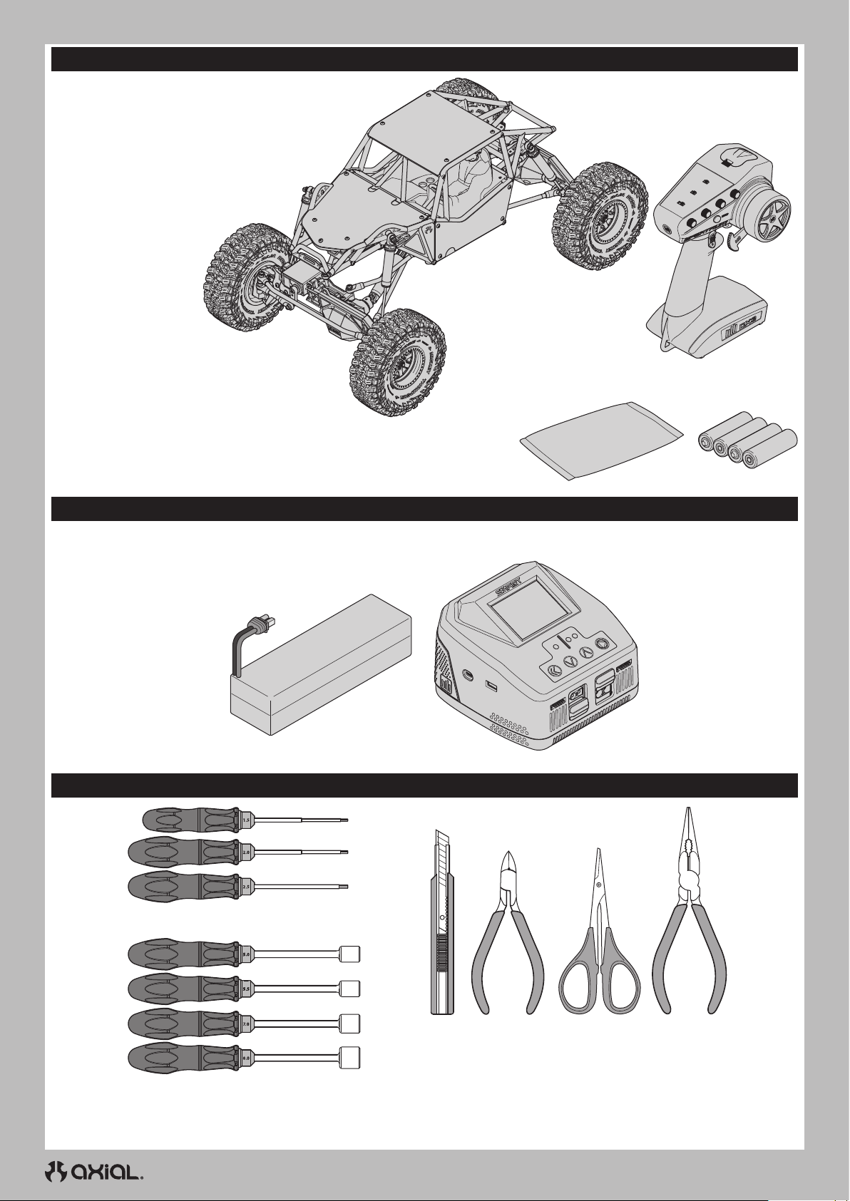
FR
CONTENU DE LA BOÎTE
• Émetteur Smart DX3 Spektrum avec direction au pouce
(SPMR2340T)
• Buggy RTR Gilamon 4roues motrices 2,2
- Moteur électrique à balais 21T Boulder 550 (AXI-2156)
- Servo 20kg S682 25T à engrenages métalliques
(SPMS682)
- Micro Servo à engrenages métalliques/boîtier
SX117AX, câble de 250mm (SPMSSX117AX)
- Récepteur DSMR 5canaux SR515
(SPMSR515)
- Variateur ESC WP
Smart à balais 70A Firma
(SPMXSE1070)
• (4) piles alcalines AA
• Sachet de pièces • (4) piles
alcalines AA
MATÉRIEL NÉCESSAIRE
• Batterie LiPo 3S
(Connecteur IC3 requis)
OUTILS RECOMMANDÉS
• Clés Allen (1,5, 2,0, 2,5mm)
• Chargeur de batterie compatible
avec la batterie de véhicule choisie
• Tourne-écrou (5,0, 5,5, 7,0, 8,0mm)
• Couteau
hobby
32
• Pince
coupante
• Ciseaux
courbes
• Pince à bec long
Page 33
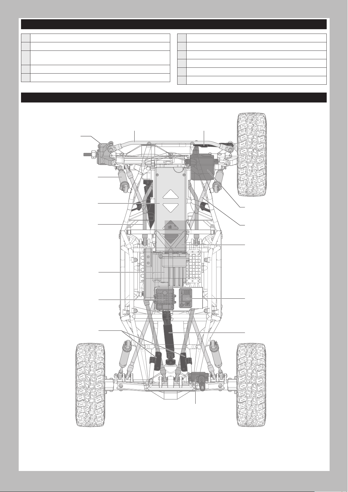
LISTE DE CONTRÔLE AVANT DE COMMENCER
FR
Lisez le manuel
Familiarisez-vous avec le véhicule et ses composants
Vérifiez que toutes les vis, en particulier les vis de fixation de
l’arbre de transmission, ont été bien serrées en usine
Chargez la batterie du véhicule
Installez 4piles AA dans l’émetteur
PIÈCES DU VÉHICULE
Tringlerie de direction
Rotule de direction
Amortisseur
Support de batterie
Mettez l’émetteur en marche
Installez la batterie du véhicule dans le véhicule
Contrôlez le bon fonctionnement des gaz et de la direction
Vérifiez la portée de votre système radio
Manœuvrez le véhicule, mettez-vous au défi, et AMUSEZ-VOUS!
Effectuez l’entretien nécessaire sur le véhicule
Barre d’accouplement
Servo de direction
Barre à 4 bras supérieure
Transmission
Variateur de vitesse
électronique (ESC)/
récepteur
Système d’éclairage à
DEL réglable Rock Light
Barre à 4 bras inférieure
Moteur
Récepteur
Arbre de transmission
33
Servo ASD
Page 34
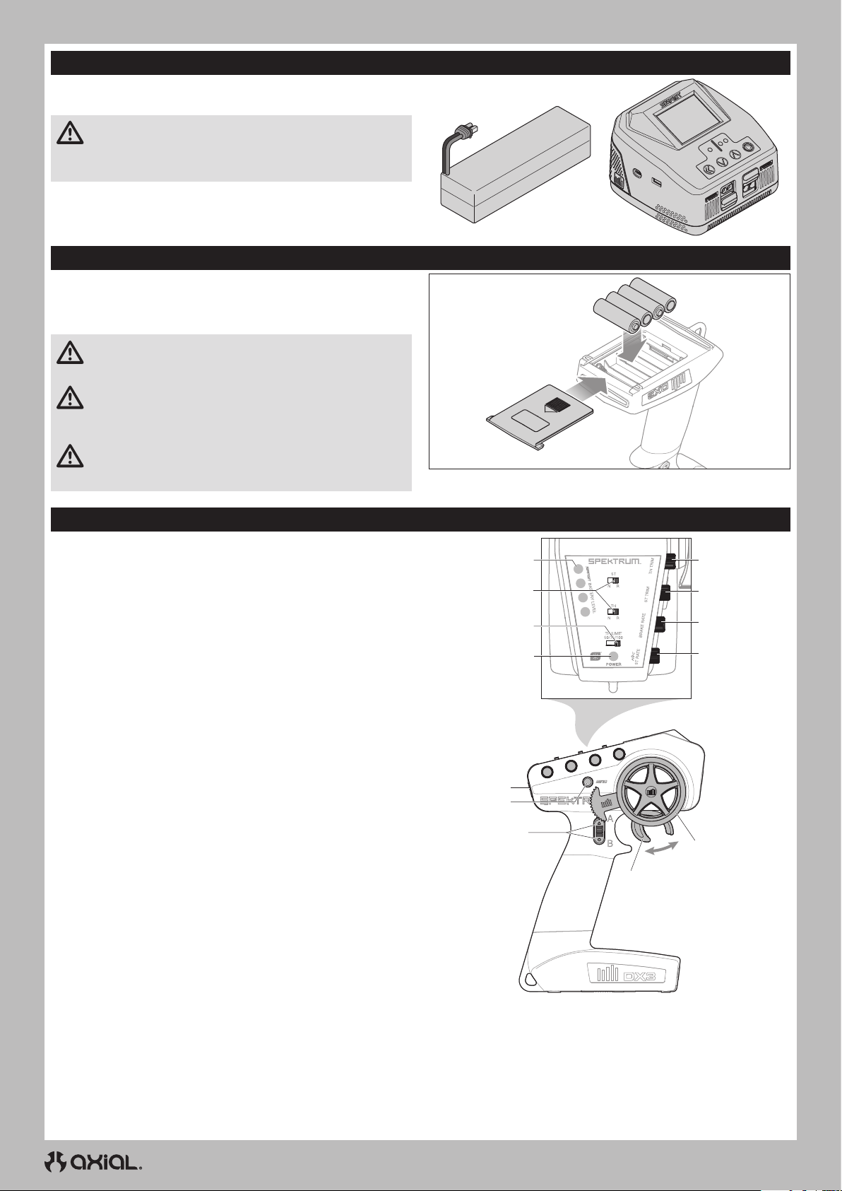
FR
CHARGEZ LA BATTERIE DU VÉHICULE
Suivez les instructions du fabricant de votre chargeur pour charger
correctement la batterie du véhicule.
ATTENTION: Utilisez uniquement des chargeurs conçus
pour charger le type de batterie choisi. L’utilisation d’un
chargeur incompatible ou de paramètres de chargeur inadaptés
peut entraîner un incendie ou une explosion de la batterie.
INSTALLATION DES PILES DE L’ÉMETTEUR
Cet émetteur nécessite 4 piles AA.
1. Retirez le couvercle du compartiment à piles.
2. Insérez les piles comme sur l’illustration.
3. Replacez le couvercle.
ATTENTION : Ne retirez jamais les piles de l’émetteur
lorsque le modèle est sous tension. Une perte de contrôle du
modèle, des dommages ou des blessures peuvent survenir.
ATTENTION: Si vous utilisez des piles rechargeables,
chargez seulement des piles rechargeables. La charge de
piles non rechargeables peut causer un incendie, entraînant des
blessures corporelles et/ou des dégâts matériels.
ATTENTION: Risque d’explosion si la batterie est remplacée
par un type de batterie non conforme. Éliminez les batteries
usagées selon les régulations nationales.
FONCTIONS DE L’ÉMETTEUR
Entraînement sélectionnable arrière droit (fonction ASD)
A.
Entraînement sélectionnable arrière gauche (fonction ASD)
B.
GAZ/FREIN
C.
VOLANT
D.
STEERING RATE (TAUX DE DIRECTION)
E.
Ajuste le point d’extrémité de la direction
BRAKE RATE (TAUX DE FREINAGE)
F.
Ajuste le point d’extrémité du freinage.
STEERING TRIM (COMPENSATEUR DE DIRECTION)
G.
Ajuste le point central de direction. En général, le compensateur de
direction est ajusté jusqu’à ce que le véhicule aille droit.
THROTTLE TRIM (COMPENSATEUR DES GAZ)
H.
Ajuste le point neutre des gaz
INDICATEUR DU NIVEAU DE LA BATTERIE SMART
I.
INVERSION DU SERVO
J.
Pour inverser le canal des gaz (TH) ou de la direction (ST), faites
basculer la position du commutateur correspondant: «N» est pour
normal, «R» est pour inversé.
THROTTLE LIMIT (LIMITE DES GAZ)
K.
Limite la sortie des gaz à 50/75/100%
Sélectionnez 50% ou 75% pour les pilotes moins expérimentés ou
lorsque vous pilotez le véhicule dans une petite zone.
DEL D’ALIMENTATION
L.
• Témoins en rouge fixe: indique la connectivité radio et une
alimentation de batterie appropriée
• Témoins clignotant en rouge: indique que la tension de la
batterie est à un niveau extrêmement bas. Remplacez les batteries
BOUTON D’ALIMENTATION
M.
BOUTON BIND (AFFECTATION)
N.
I
J
K
L
M
N
A/B
C
H
G
F
E
D
34
Page 35
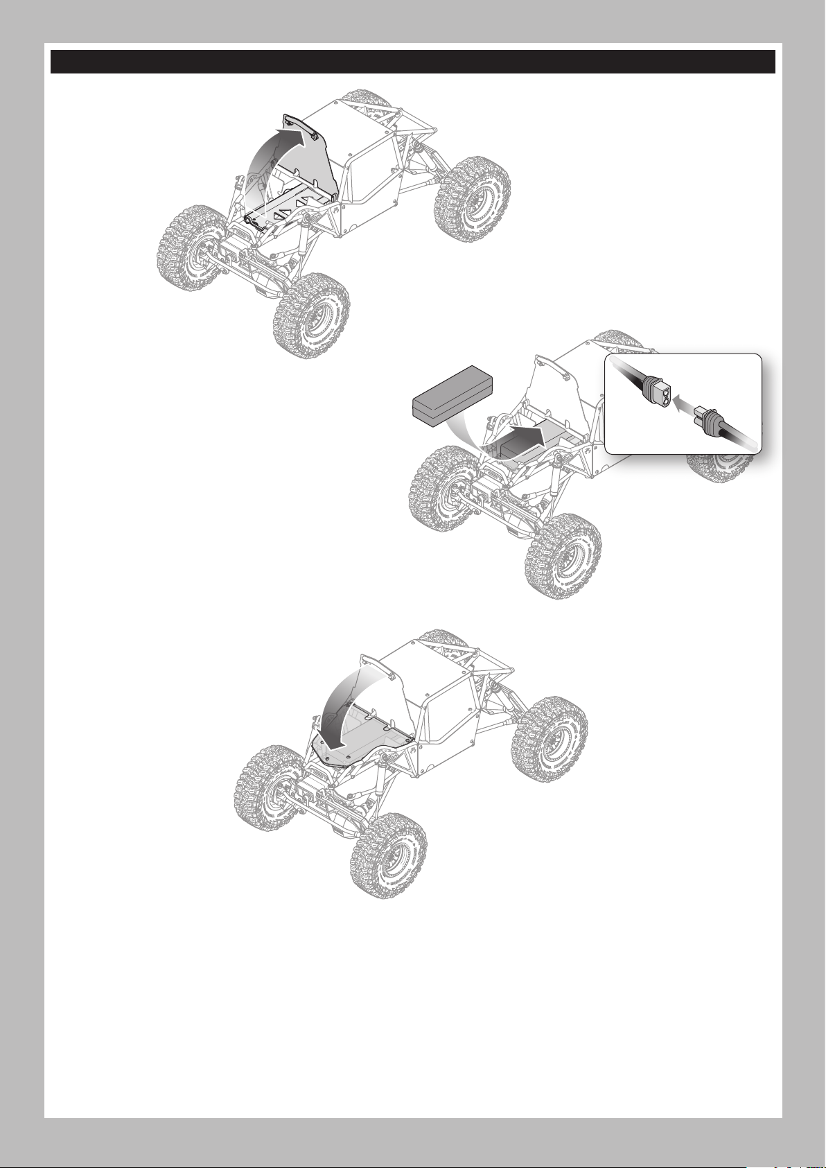
INSTALLEZ LA BATTERIE DU VÉHICULE
1. Tirez sous la barre avant du capot pour
accéder au support de batterie.
2. Installez la batterie recommandée pour le véhicule dans le
compartiment de batterie, en orientant les fils d’alimentation
vers l’avant.
3. Raccordez le fil d’alimentation de la batterie au connecteur
du variateur ESC en respectant bien la polarité.
4. Fixez la batterie dans le compartiment à l’aide de la bande
velcro installée.
CONSEIL: Empêchez la connexion du câble de la batterie
de se déplacer en faisant passer la bande velcro par-dessus
le câble d’alimentation.
FR
5. Appuyez sur l’avant du capot jusqu’à ce qu’il s’enclenche
correctement dans les deux coins avant.
35
Page 36
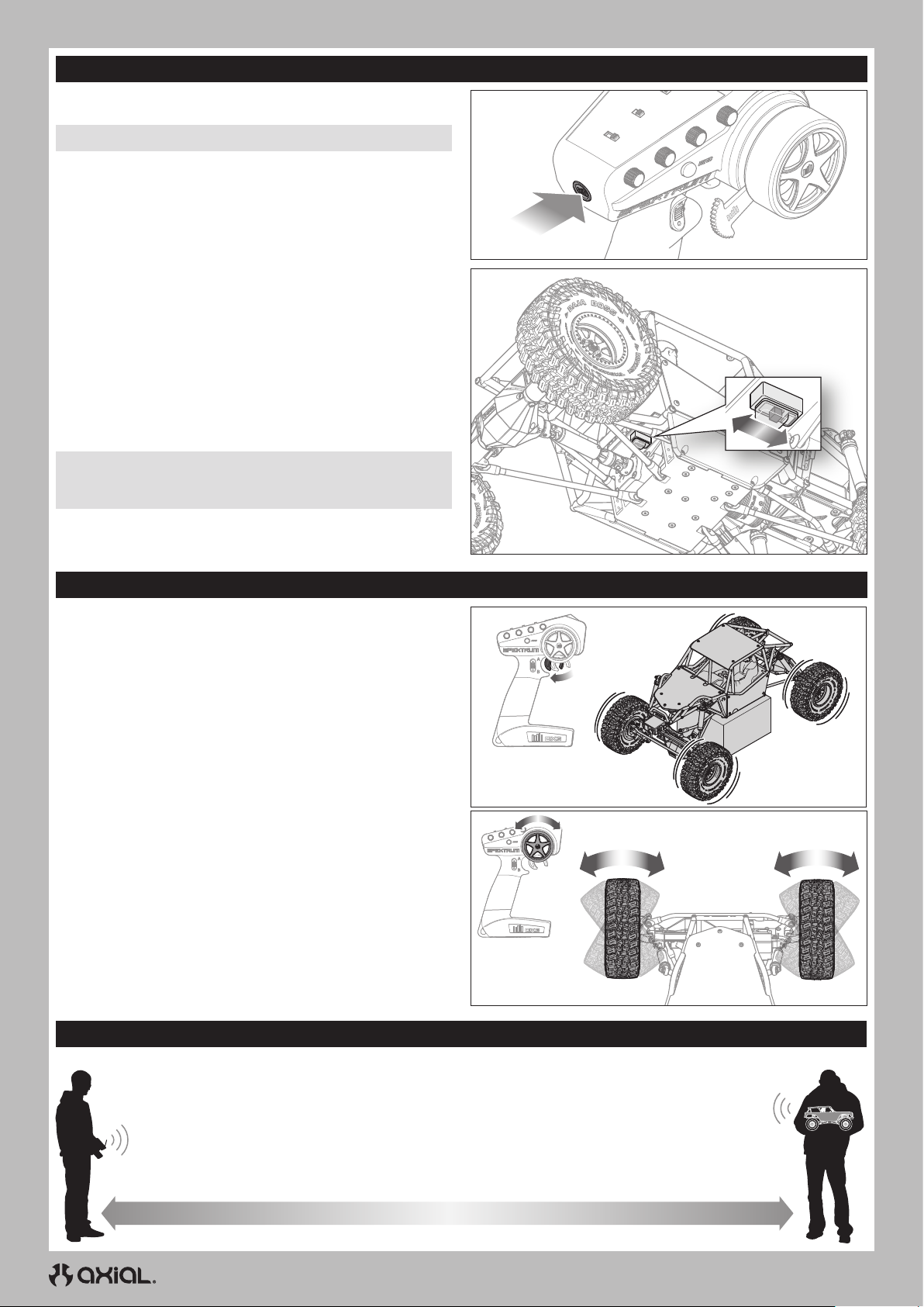
FR
MISE SOUS TENSION ET HORS TENSION
ALLUMAGE
1. Allumez l’émetteur.
REMARQUE: Allumez toujours l’émetteur, puis le véhicule.
2. Allumez le véhicule en faisant glisser l’interrupteur vers l’arrière
du véhicule.
ALIMENTATION COUPÉE
1. Éteignez le véhicule en faisant glisser l’interrupteur vers l’avant du
véhicule.
REMARQUE: éteignez toujours le véhicule avant d’éteindre
l’émetteur. Si vous éteignez l’émetteur en premier, vous risquez de
perdre le contrôle de la machine.
2. Éteignez l’émetteur.
3. Débranchez la batterie du variateur ESC.
4. Retirez la batterie du véhicule pour la charger ou la ranger.
Power
TEST DE CONTRÔLE
Effectuez un test des commandes sans que les roues du véhicule ne
touchent le sol.
• Pour faire rouler les roues vers l’avant, tirez sur la manette.
IMPORTANT: le système d’engrenages de transmission standard
confère à l’essieu arrière du véhicule une «sous-multiplication».
Les roues arrière tournent plus lentement que les roues avant.
• Pour inverser le mouvement des roues, attendez que les roues
s’arrêtent, puis poussez la manette vers l’avant.
• Si les roues tournent lorsque le véhicule est allumé, ajustez le
bouton TH TRIM jusqu’à ce qu’elles ne tournent plus sans entrée des
gaz.
• Tourner le volant de l’émetteur à gauche et à droite, en vérifiant que
les roues du véhicule tournent dans le sens correspondant à l’entrée
de l’émetteur.
Placez le véhicule sur le sol et actionnez lentement les gaz:
• Lorsque le véhicule avance, il doit suivre une ligne droite sans
aucune entrée du volant. Si ce n’est pas le cas, réglez le bouton ST
TRIM à gauche ou à droite jusqu’à ce que le véhicule suive une ligne
droite sans avoir à rectifier la trajectoire à l’aide du volant.
VÉRIFICATION DE LA PORTÉE DU SYSTÈME RADIO
Contrôlez le système radio pour vous assurer de son bon fonctionnement et de sa portée adaptée avant d’utiliser le véhicule.
1. Allumez l’émetteur.
2. Connectez la batterie dans le véhicule.
3. Demandez à un ami de tenir le véhicule tout en gardant les mains et les vêtements amples à l’écart des pièces
en mouvement.
4. Éloignez-vous jusqu’à la distance maximale prévue d’utilisation du véhicule.
5. Tournez le volant de chaque côté et faites fonctionner l’accélérateur en marche avant et arrière, en vous assurant
qu’il n’y a aucun comportement irrégulier.
6. Si vous constatez un comportement irrégulier, NE PAS utiliser le véhicule. Appelez le service clientèle pour obtenir de l’aide.
36
Page 37
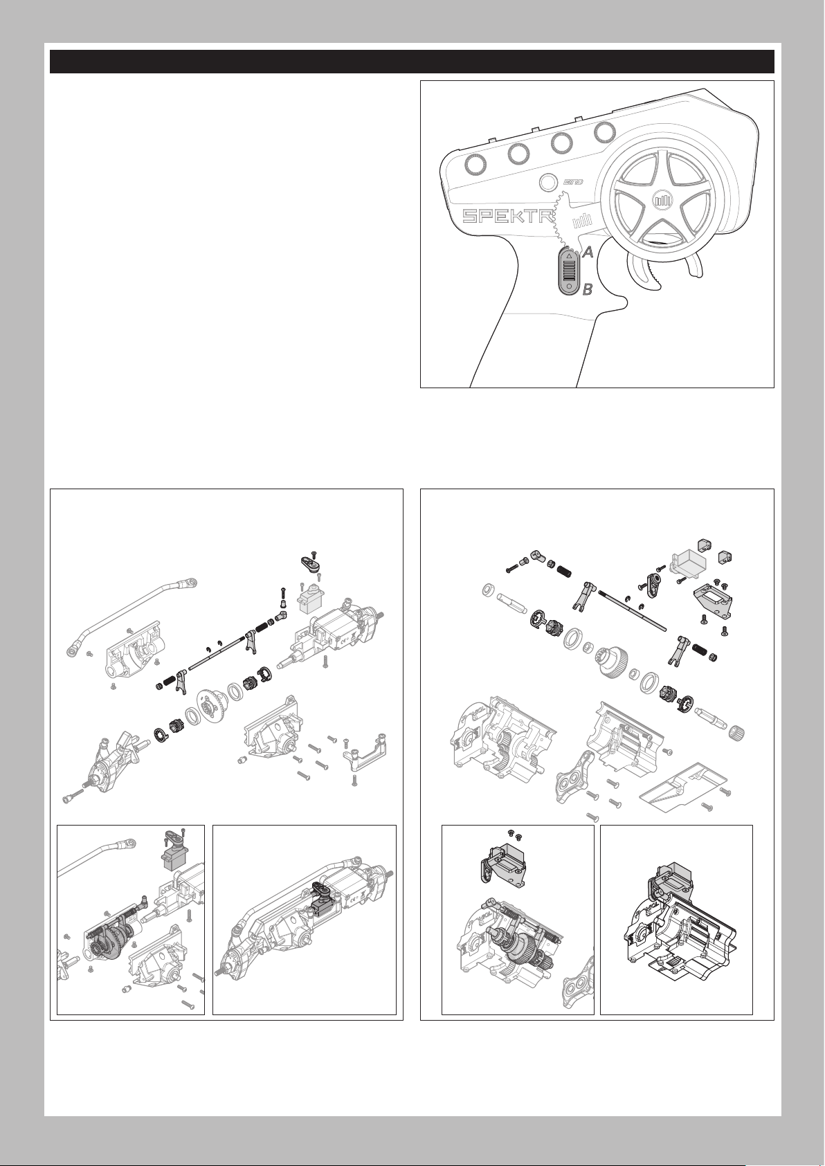
ENTRAÎNEMENT SÉLECTIONNABLE AXIAL (ASD)
Un système d’entraînement sélectionnable axial (ASD) est préinstallé
sur l’essieu arrière du véhicule. L’ASD permet au pilote de verrouiller
la roue arrière gauche ou droite, ce qui permet au véhicule d’effectuer
des virages très serrés en pivotant autour de la roue «verrouillée».
Pour activer l’ASD:
1. Appuyez sur le bouton A ou B et maintenez-le enfoncé.
• Le boutonA active le verrouillage de la roue gauche.
• Le boutonB active le verrouillage de la roue droite.
2. Tournez le volant et appuyez lentement ou par intermittence sur
les gaz pour faire pivoter le véhicule autour de la roue verrouillée.
CONSEIL: si vous tournez le volant dans la direction de la roue
verrouillée, vous obtenez un virage serré dans cette direction.
Si vous tournez le volant dans la direction opposée à la roue
verrouillée, vous obtenez un glissement lent dans la direction
opposée à la roue verrouillée.
3. Relâchez le boutonA ou B et les gaz pour «déverrouiller» la roue.
CONSEIL: Il peut être nécessaire d’appuyer légèrement sur la
marche arrière pour déclencher l’ASD.
FONCTIONS ASD SUPPLÉMENTAIRES (EN OPTION)
Avec l’achat supplémentaire d’un servo et de l’ensemble de pièces
ASD: AXP8 (AXI-2191) - le système d’entraînement sélectionnable
axial peut être ajouté à l’essieu avant ou à la transmission (ou aux
deux) avec l’achat de deux ensembles et de servos.
IMPORTANT: le contrôle des fonctions optionnelles
supplémentaires nécessite un émetteur doté de plus de trois
canaux, tel que l’émetteur DSMR Spektrum™ DX6 Rugged à 6canaux
(SPMR6215).
FR
INSTALLATION DE L’ASD SUR L’ESSIEU AVANT (EN OPTION)
Pour activer l’entraînement sélectionnable à l’avant, à gauche et à droite
Servo non inclus (SPMSSX117AX recommandé)
INSTALLATION DE L’ASD SUR LA TRANSMISSION (EN OPTION)
Pour activer l’entraînement sélectionnable à l’avant et à l’arrière
Servo non inclus (SPMSSX117AX recommandé)
37
Page 38
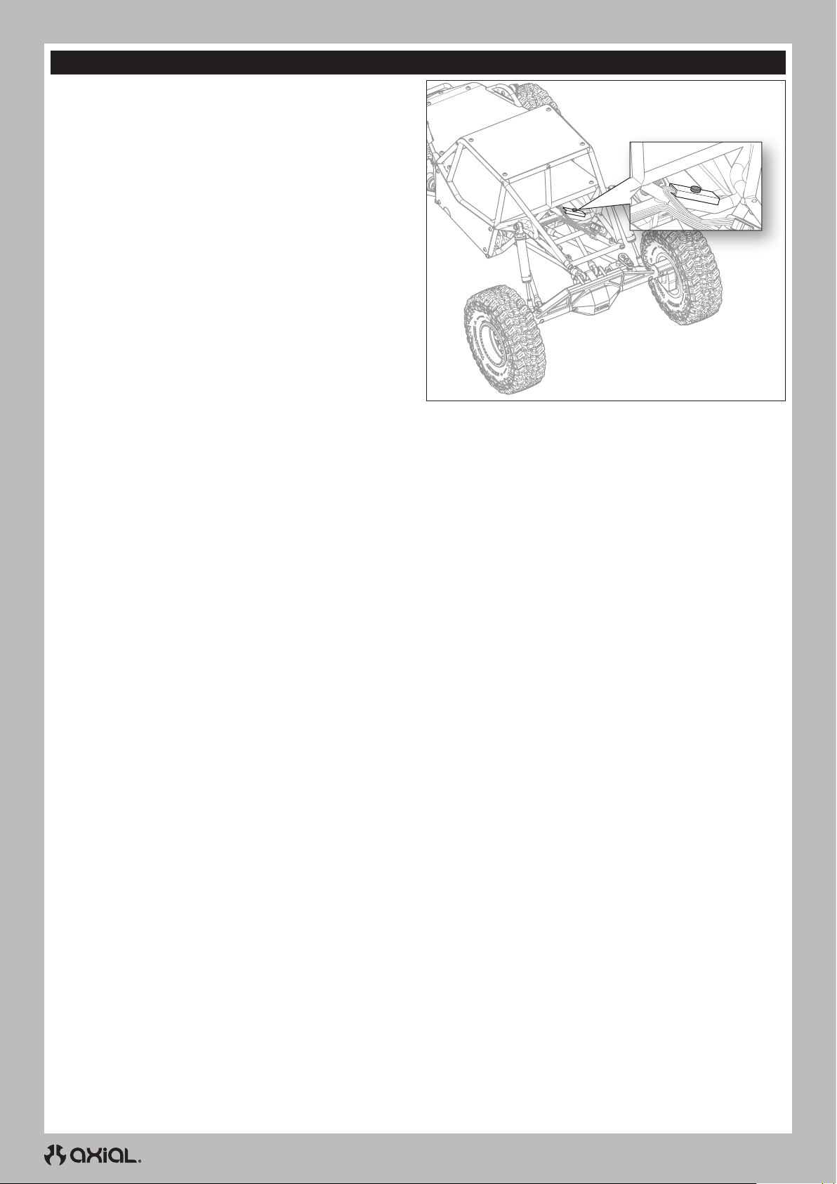
FR
SYSTÈME D’ÉCLAIRAGE À DEL ROCKLIGHTS
Le véhicule est livré avec un système d’éclairage à DEL RVB Rock
Lights permettant de sélectionner les couleurs.
Pour faire fonctionner les feux:
1. Allumez le véhicule.
2. Appuyez sur le bouton de commande des feux, situé à l’arrière de
la cage de retournement centrale, comme illustré. Les feux DEL
s’allument en rouge à la première pression.
3. Faites défiler les sept couleurs disponibles en appuyant plusieurs
fois sur le bouton de commande jusqu’à ce que la couleur
souhaitée s’affiche.
4. Éteignez les feux en faisant défiler les couleurs à l’aide du bouton
de commande jusqu’à ce que les feux s’éteignent.
SÉQUENCE DE LED :
1. Rouge
2. Vert
3. Bleu
4. Jaune
5. Violet
6. Bleu sarcelle
7. Blanc
8. Éteint
38
Page 39
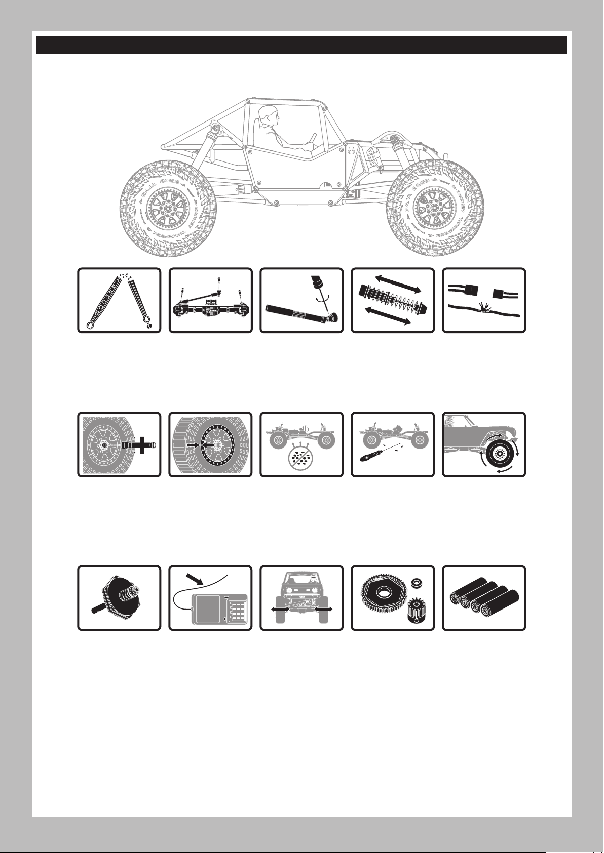
ENTRETIEN DU VÉHICULE
Tout comme une voiture ou un camion grandeur nature, votre véhicule télécommandé doit être entretenu régulièrement pour conserver une
performance optimale. L’entretien préventif permet également d’éviter toute casse superflue pouvant entraîner des réparations coûteuses. Voici
ci-dessous quelques suggestions pour entretenir correctement votre véhicule.
FR
Remplacez les pièces
visiblement tordues ou
cassées
Vérifiez que les écrous
de roue sont bien
serrés
Contrôlez l’usure des
joints à rotule dans la
tringlerie de direction
et de suspension
(remplacez si
nécessaire)
Assurez-vous que les
talons de roue sont
toujours fermement
collés sur toute la
circonférence de la
jante
Contrôlez les vis de
fixation de l’arbre
de transmission et
appliquez du frein-filet
si nécessaire
Assurez-vous que le
châssis est exempt de
crasse et de débris
Vérifiez que les
amortisseurs
absorbent
efficacement les
chocs et de façon
fluide
Vérifiez qu’il n’y a
aucune vis desserrée
sur le châssis, en
particulier les vis de
blocage des rotules,
des moyeux en C et
des essieux
Assurez-vous qu’il n’y
a aucune connexion
lâche ou aucun fil
effiloché
Vérifiez que la
transmission
fonctionne de façon
fluide, sans grippages
Le cas échéant,
contrôlez le bon
fonctionnement de
l’embrayage
Vérifiez que l’antenne
du récepteur n’est pas
endommagée
Vérifiez que la
direction n’est pas
grippée
39
Vérifiez que les
engrenages à pignons
et les engrenages
cylindriques ne sont
pas endommagés
Remplacez les
piles de l’émetteur
lorsque l’émetteur
vous y invite, comme
décrit dans la
section Fonctions de
l’émetteur
Page 40
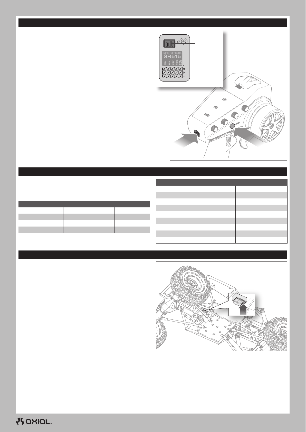
FR
AFFECTATION DE VOTRE ÉMETTEUR ET VOTRE RÉCEPTEUR
L’affectation est le processus de programmation du récepteur qui vise
à reconnaître le code GUID (identificateur global unique) d’un émetteur
unique spécifique. L’émetteur et le récepteur sont affectés en usine. Si
vous devez les réaffecter, suivez les instructions ci-dessous.
1. Branchez une batterie complètement chargée sur le variateur
ESC/récepteur.
2. Maintenez enfoncé le bouton d’affectation sur le récepteur.
3. Allumez le récepteur. La DEL rouge clignote, indiquant que le
récepteur est en mode affectation.
4. Relâchez le bouton d’affectation.
5. Avec la commande des gaz en position neutre, maintenez enfoncé
le bouton d’affectation de l’émetteur tout en l’allumant pour le
mettre en mode affectation.
IMPORTANT: La commande d’accélération doit être en position
neutre pour régler la sécurité intégrée.
6. Le processus d’affectation est terminé lorsque la DEL verte du
récepteur reste allumée.
Vous devez réaffecter lorsque différentes positions de sécurité
intégrée sont nécessaires, par ex. lorsque l’inversion des gaz ou de la
direction a été modifiée.
Bouton
d’affectation
Bouton
d’alimentation
INDICATEUR DEL ET SONS DU MOTEUR
Lors de la mise sous tension du variateur ESC, la DEL se mettra à
clignoter et le moteur émettra une série de bips pour indiquer son état. Il
commence par afficher la sélection du mode batterie, puis le réglage de
la force de freinage, et, pour finir, il indique qu’il est prêt à fonctionner.
Fonction État des témoins DEL Son du moteur
Batterie Ni-MH/Ni-CD 1clignotement 1bip court
Batterie 2S Li-Po 2clignotements 2bips courts
Batterie v Li-Po 3clignotements 3bips courts
Variateur ESC prêt 1 clignotement long 1 bip long
Arrêt OFF (Arrêt)
Accélération partielle vers l’avant Clignotements
Accélération partielle vers l’arrière Clignotements
Freinage partiel Clignotements
Tension de batterie faible Clignotements
Surchauffe Clignotements
En cours de service État des témoins DEL
Accélération complète Fixe
Accélération complète Fixe
Freinage complet Fixe
ÉTALONNAGE DU VARIATEUR ESC ET DE L’ÉMETTEUR
Il est important d’étalonner le variateur ESC sur l’émetteur afin que le
variateur ESC s’adapte à la plage des gaz de votre émetteur. Si vous
n’étalonnez pas le variateur ESC sur votre système radio, le variateur
ESC ne fonctionnera pas correctement. Réglez la sécurité intégrée
avec votre radio sur une position neutre pour vous assurer que le
moteur s’arrête en cas de perte de signal.
1. Allumez l’émetteur.
2. Réglez le commutateur de limitation des gaz sur 100% et centrez
le compensateur des gaz avant de procéder à l’étalonnage.
3. Branchez une batterie au variateur ESC.
4. Pressez et maintenez appuyé le bouton de programmation sur le
boîtier du commutateur, tout en allumant le variateur ESC.
La DEL rouge sur le variateur ESC commencera à clignoter et le
moteur émettra un bip.
5. Relâchez le bouton de programmation dans les 3secondes.
IMPORTANT: le variateur ESC entrera en mode de
programmation si le bouton de programmation n’est pas relâché
dans les 3 secondes. Si le variateur ESC entre en mode de
programmation, éteignez le véhicule et revenez à l’étape4.
6. Avec la commande des gaz et le compensateur des gaz en
position neutre, appuyez sur le bouton de programmation et
maintenez-le enfoncé. La DEL rouge clignotera une fois et le
moteur émettra une tonalité.
CONSEIL: Les bips sonores émis par le moteur peuvent être
difficiles à entendre. Utilisez l’état des témoins DEL pour vérifier
les paramètres.
7. Poussez la commande des gaz sur plein régime. Appuyez sur le
bouton de programmation et relâchez-le. La DEL rouge clignotera
deux fois et le moteur émettra deux tonalités.
8. Maintenez la commande des gaz sur la position arrière complet.
Appuyez sur le bouton de programmation et relâchez-le. La DEL
rouge clignotera trois fois et le moteur émettra trois tonalités.
9. Allumez le système à l’aide du commutateur ON/OFF (Marche/Arrêt).
10. Allumez le système à l’aide du commutateur ON/OFF (Marche/
Arrêt). Le système est prêt à opérer
Bouton
d’affectation
40
Page 41

GUIDE DE DÉPANNAGE
PROBLÈME CAUSE POSSIBLE SOLUTION
Le système ne se connecte pas
Le récepteur passe en mode sécurité
intégrée à une courte distance de
l’émetteur
Le récepteur cesse de répondre en cours
de service
Le véhicule ne bouge pas
Perte de contrôle du véhicule
La fonction de direction et/ou des gaz est
inversée
Variateur ESC allumé - Aucune fonction
moteur, tonalité audible ou DEL
Moteur- S’arrête et la DEL clignote
Moteur- Accélère régulièrement
Moteur- Ne tourne pas de façon continue
en réponse à une accélération
Moteur- Ralentit mais ne s’arrête pas
Servo de direction- Fonctionne; le moteur
ne tourne pas
Direction/moteur- ne fonctionne pas
Véhicule- Ne fonctionne pas à pleine
vitesse
L’émetteur et le récepteur sont trop proches
Vous vous trouvez à proximité d’objets
métalliques
Le récepteur est affecté à la mémoire
d’un modèle différent
Votre émetteur a été placé en mode affectation
et n’est plus affecté à votre récepteur
Vérifiez que l’antenne du récepteur
n’est pas endommagée
Faible tension de la batterie du récepteur.
Si la tension de la batterie est faible, il est
possible qu’elle tombe provisoirement en
dessous de 3,5V, entraînant une baisse de
tension du récepteur, puis une reconnexion
Fils ou connecteurs desserrés ou
endommagés entre la batterie et le récepteur
Les piles ne sont pas installées
correctement dans l’émetteur
Batterie faible ou absente dans le véhicule Installez une batterie venant d’être chargée dans le véhicule
Moteur endommagé Remplacez le moteur
Câblage effiloché ou cassé Remplacez tout fil endommagé
Le variateur ESC est coupé par le circuit
de protection contre la surchauffe
Mauvais placement de l’antenne
Batteries faibles ou absentes dans
l’émetteur ou le véhicule
Mauvaise position neutre ou du compensateur
Mauvaise connexion du récepteur et/ou
de la batterie
La course du servo est inversée au
niveau de l’émetteur
Les câbles du moteur sont mal
connectés
Problème de batterie/connexion
Variateur/commutateur ESC
endommagé
Moteur endommagé Réparez/remplacez
Protection contre les baisses de
tension
Protection contre la surchauffe
Problème de batterie Réparez les fils endommagés/remplacez la batterie
Engrenage incorrect Ajustez/remplacez l’engrenage
Moteur usé ou endommagé Réparez/remplacez le moteur
Variateur ESC/moteur endommagé Réparez/remplacez les fils ou le moteur/variateur ESC
Calibrage incorrect de l’émetteur/du
variateur ESC
Moteur endommagé
Calibrage incorrect de l’émetteur/du
variateur ESC
Tension de batterie faible Rechargez/remplacez
Mémoire du modèle incorrect
sélectionnée sur l’émetteur
Récepteur non affecté à l’émetteur
Problème de batterie Rechargez/remplacez
Calibrage incorrect de l’émetteur/du
variateur ESC
Éloignez l’émetteur d’environ 2 à 4m du récepteur
Déplacez-vous dans une zone contenant moins de métal
Assurez-vous que la mémoire du bon modèle est active dans votre
émetteur
Réaffectez l’émetteur et le récepteur, puis recalibrez
Assurez-vous que l’antenne de votre récepteur est protégée
et placée aussi haut que possible
Remplacez le récepteur ou contactez l’assistance produit
de Horizon
Chargez la batterie du récepteur ou du véhicule. Les
récepteurs Spektrum nécessitent une tension de service
minimale de 3,5V
Vérifiez les fils et la connexion entre la batterie et le récepteur.
Réparez ou remplacez les fils et/ou les connecteurs
Assurez-vous que les piles sont correctement installées dans
l’émetteur
Laissez le variateur ESC refroidir complètement
Assurez-vous que l’antenne de l’émetteur n’est pas bloquée et
que l’antenne du récepteur est bien placée
Installez une batterie venant d’être chargée dans le véhicule et
des piles neuves dans l’émetteur
Ajustez le compensateur de direction
Contrôlez toutes les connexions du récepteur et de la batterie
Mettez le commutateur d’inversion de servo de l’émetteur à la
bonne position
Vérifiez que tous les câbles du moteur sont bien connectés et
sont à la bonne polarité
Rechargez/remplacez la batterie. Fixez tous les
branchements
Réparez/remplacez le variateur/commutateur ESC
Lorsque la DEL du variateur ESC clignote, rechargez/
remplacez la batterie
Lorsque la DEL clignote, laissez le moteur/variateur ESC
refroidir, modifiez la configuration ou l’engrenage pour
éviter une surchauffe
Réglez le débattement des gaz/les autres paramètres des
gaz sur l’émetteur/le variateur ESC. Répétez la procédure
de calibrage du variateur ESC
Testez le moteur en dehors du système du véhicule,
réparez/remplacez le moteur selon le besoin
Réglez le débattement des gaz/les autres paramètres des
gaz sur l’émetteur/le variateur ESC. Répétez la procédure
de calibrage du variateur ESC
Sélectionnez les bons paramètres de modèle sur votre
émetteur; consultez le manuel de l’émetteur et/ou du récepteur
Affectez l’émetteur au récepteur; consultez le manuel de
l’émetteur et/ou du récepteur
Réglez le débattement des gaz/les autres paramètres des
gaz sur l’émetteur/le variateur ESC. Répétez la procédure
de calibrage du variateur ESC
FR
41
Page 42

FR
GARANTIE ET RÉPARATIONS
Durée de la garantie
Garantie exclusive - Horizon Hobby, LLC (Horizon) garantit que le
Produit acheté (le « Produit ») sera exempt de défauts matériels et
de fabrication à sa date d’achat par l’Acheteur. La durée de garantie
correspond aux dispositions légales du pays dans lequel le produit
aété acquis. La durée de garantie est de 6 mois et la durée d’obligation
de garantie de 18 mois à l’expiration de la période de garantie.
Limitations de la garantie
(a) La garantie est donnée à l’acheteur initial (« Acheteur ») et
n’est pas transférable. Le recours de l’acheteur consiste en
la réparation ou en l’échange dans le cadre de cette garantie.
La garantie s’applique uniquement aux produits achetés chez
un revendeur Horizon agréé. Les ventes faites à des tiers ne
sont pas couvertes par cette garantie. Les revendications en
garantie seront acceptées sur fourniture d’une preuve d’achat
valide uniquement. Horizon se réserve le droit de modifier les
dispositions de la présente garantie sans avis préalable et
révoque alors les dispositions de garantie existantes.
(b) Horizon n’endosse aucune garantie quant à la vendabilité du
produit ou aux capacités et à la forme physique de l’utilisateur
pour une utilisation donnée du produit. Il est de la seule
responsabilité de l’acheteur de vérifier si le produit correspond à
ses capacités et à l’utilisation prévue.
(c) Recours de l’acheteur – Il est de la seule discrétion d’Horizon de
déterminer si un produit présentant un cas de garantie sera réparé ou
échangé. Ce sont là les recours exclusifs de l’acheteur lorsqu’un défaut
est constaté.
Horizon se réserve la possibilité de vérifier tous les éléments utilisés
et susceptibles d’être intégrés dans le cas de garantie. La décision
de réparer ou de remplacer le produit est du seul ressort d’Horizon.
La garantie exclut les défauts esthétiques ou les défauts provoqués
par des cas de force majeure, une manipulation incorrecte du produit,
une utilisation incorrecte ou commerciale de ce dernier ou encore des
modifications de quelque nature qu’elles soient.
La garantie ne couvre pas les dégâts résultant d’un montage ou d’une
manipulation erronés, d’accidents ou encore du fonctionnement ainsi
que des tentatives d’entretien ou de réparation non effectuées par
Horizon. Les retours effectués par le fait de l’acheteur directement à
Horizon ou à l’une de ses représentations nationales requièrent une
confirmation écrite.
Limitation des dommages
Horizon ne saurait être tenu pour responsable de dommages
conséquents directs ou indirects, de pertes de revenus ou de pertes
commerciales, liés de quelque manière que ce soit au produit et ce,
indépendamment du fait qu’un recours puisse être formulé en relation
avec un contrat, la garantie ou l’obligation de garantie. Par ailleurs,
Horizon n’acceptera pas de recours issus d’un cas de garantie lorsque
ces recours dépassent la valeur unitaire du produit. Horizon n’exerce
aucune influence sur le montage, l’utilisation ou la maintenance du
produit ou sur d’éventuelles combinaisons de produits choisies par
l’acheteur. Horizon ne prend en compte aucune garantie et n‘accepte
aucun recours pour les blessures ou les dommages pouvant en résulter.
Horizon Hobby ne saurait être tenu responsable d’une utilisation ne
respectant pas les lois, les règles ou règlementations en vigueur.
En utilisant et en montant le produit, l’acheteur accepte sans
restriction ni réserve toutes les dispositions relatives à la garantie
figurant dans le présent document. Si vous n’êtes pas prêt, en tant
qu’acheteur, à accepter ces dispositions en relation avec l’utilisation
du produit, nous vous demandons de restituer au vendeur le produit
complet, non utilisé et dans son emballage d’origine.
Indications relatives à la sécurité
Ceci est un produit de loisirs perfectionné et non un jouet. Il doit être
utilisé avec précaution et bon sens et nécessite quelques aptitudes
mécaniques ainsi que mentales. L’incapacité à utiliser le produit de
manière sure et raisonnable peut provoquer des blessures et des
dégâts matériels conséquents. Ce produit n’est pas destiné à être
utilisé par des enfants sans la surveillance par un tuteur. La notice
d’utilisation contient des indications relatives à la sécurité ainsi que
des indications concernant la maintenance et le fonctionnement du
produit. Il est absolument indispensable de lire et de comprendre ces
indications avant la première mise en service. C’est uniquement ainsi
qu’il sera possible d’éviter une manipulation erronée et des accidents
entraînant des blessures et des dégâts. Horizon Hobby ne saurait être
tenu responsable d’une utilisation ne respectant pas les lois, les règles
ou règlementations en vigueur.
Questions, assistance et réparations
Votre revendeur spécialisé local et le point de vente ne peuvent
effectuer une estimation d’éligibilité à l’application de la garantie sans
avoir consulté Horizon. Cela vaut également pour les réparations sous
garantie. Vous voudrez bien, dans un tel cas, contacter le revendeur
qui conviendra avec Horizon d’une décision appropriée, destinée à
vous aider le plus rapidement possible.
Maintenance et réparation
Si votre produit doit faire l’objet d’une maintenance ou d’une
réparation, adressez-vous soit à votre revendeur spécialisé, soit
directement à Horizon. Emballez le produit soigneusement. Veuillez
noter que le carton d’emballage d’origine ne suffit pas, en règle
générale, à protéger le produit des dégâts pouvant survenir pendant
le transport. Faites appel à un service de messagerie proposant une
fonction de suivi et une assurance, puisque Horizon ne prend aucune
responsabilité pour l’expédition du produit jusqu’à sa réception
acceptée. Veuillez joindre une preuve d’achat, une description
détaillée des défauts ainsi qu’une liste de tous les éléments distincts
envoyés. Nous avons de plus besoin d’une adresse complète, d’un
numéro de téléphone (pour demander des renseignements) et d’une
adresse de courriel.
Garantie et réparations
Les demandes en garantie seront uniquement traitées en présence
d’une preuve d’achat originale émanant d’un revendeur spécialisé
agréé, sur laquelle figurent le nom de l’acheteur ainsi que la date
d’achat. Si le cas de garantie est confirmé, le produit sera réparé.
Cette décision relève uniquement d’Horizon Hobby.
Réparations payantes
En cas de réparation payante, nous établissons un devis que nous
transmettons à votre revendeur. La réparation sera seulement
effectuée après que nous ayons reçu la confirmation du revendeur.
Le prix de la réparation devra être acquitté au revendeur. Pour les
réparations payantes, nous facturons au minimum 30 minutes de travail
en atelier ainsi que les frais de réexpédition. En l’absence d’un accord
pour la réparation dans un délai de 90 jours, nous nous réservons la
possibilité de détruire le produit ou de l’utiliser autrement.
ATTENTION: Nous n’effectuons de réparations payantes que
pour les composants électroniques et les moteurs. Les réparations
touchant à la mécanique, en particulier celles des hélicoptères et
des voitures radiocommandées, sont extrêmement coûteuses et
doivent par conséquent être effectuées par l’acheteur lui-même.
10/15
INFORMATIONS DE CONTACT POUR GARANTIE ET RÉPARATION
Pays d’achat Horizon Hobby Numéro de téléphone/E-mail Adresse
Union européenne
42
Hanskampring 9
D 22885 Barsbüttel, Germany
Page 43

INFORMATION IC
CAN ICES-3 (B)/NMB-3(B)
IC: 6157A-KATY1T
6157A-SRIRVINGV
Ce dispositif contient un/des émetteur(s)/récepteur(s) non
soumis à licence conforme(s) aux CNR d’Innovation, Sciences et
Développement économique Canada. Son utilisation est soumise aux
deux conditions suivantes:
1. Cet appareil ne doit pas causer d’interférences.
2. Cet appareil doit accepter toutes les interférences, y compris celles
pouvant entraîner un dysfonctionnement.
INFORMATIONS DE CONFORMITÉ POUR L’UNION EUROPÉENNE
EU COMPLIANCE STATEMENT:
Axial Gilamon Trail Buggy RTR (AXI-1207)
Par la présente, Horizon Hobby, LLC déclare que cet
appareil est conforme aux directives suivantes: Directive relative aux
équipements radioélectriques 2014/53/UE; Directive RoHS 2 2011/65/U;
Directive RoHS 3 - Modifiant 2011/65/UE Annexe II 2015/863.
Le texte complet de la déclaration de conformité UE est disponible à
l’adresse Internet suivante: https://www.horizonhobby.com/content/
support-render-compliance.
Gamme de fréquences sans fil / Puissance de sortie sans fil
Émetteur
2402.0 - 2478.0 MHz
17.7 dBm
Récepteur
2404-2476MHz
-1.33dBm
Fabricant officiel de l’UE :
Horizon Hobby, LLC
2904 Research Road
Champaign, IL 61822 USA
Importateur officiel de l’UE :
Horizon Hobby, GmbH
Hanskampring 9
22885 Barsbüttel Germany
DIRECTIVE DEEE:
L’étiquette de cet appareil respecte la directive européenne
2012/19/UE en matière de déchets des équipements
électriques et électroniques (DEEE). Cette étiquette indique
que ce produit ne doit pas être jeté avec les déchets
ménagers, mais déposé dans une installation appropriée
afin de permettre sa récupération et son recyclage.
FR
43
Page 44
IT
AVVISO
Tutte le istruzioni, le garanzie e gli altri documenti pertinenti sono soggetti a cambiamenti a totale discrezione di Horizon Hobby, LLC. Per una
documentazione aggiornata sul prodotto, visitare il sito horizonhobby.com o towerhobbies.com e fare clic sulla sezione Support del prodotto.
CONVENZIONI TERMINOLOGICHE
Nella documentazione relativa al prodotto vengono utilizzati i seguenti termini per indicare i vari livelli di pericolo potenziale durante l’uso del
prodotto:
AVVERTENZA: Indica procedure che, se non debitamente seguite, determinano il rischio di danni alle cose, danni collaterali e gravi lesioni
alle persone O il rischio elevato di lesioni superficiali alle persone.
ATTENZIONE: Indica procedure che, se non debitamente seguite, determinano il rischio di danni alle cose E di gravi lesioni alle persone.
AVVISO: Indica procedure che, se non debitamente seguite, possono determinare il rischio di danni alle cose E il rischio minimo o nullo
di lesioni alle persone.
AVVERTENZA: leggere TUTTO il manuale di istruzioni e familiarizzare con le caratteristiche del prodotto prima di farlo funzionare. Un
uso improprio del prodotto può causare danni al prodotto stesso e alle altre cose e gravi lesioni alle persone.
Questo modello è un prodotto sofisticato per appassionati di modellismo. Deve essere azionato in maniera attenta e responsabile e richiede
alcune conoscenze basilari di meccanica. L’uso improprio o irresponsabile di questo prodotto può causare lesioni alle persone e danni al
prodotto stesso o alle altre cose. Questo prodotto non deve essere utilizzato dai bambini senza la diretta supervisione di un adulto. Non tentare
di smontare, utilizzare componenti incompatibili o modificare il prodotto in nessun caso senza previa approvazione di horizon hobby, llc. Questo
manuale contiene le istruzioni per la sicurezza, l’uso e la manutenzione del prodotto. È fondamentale leggere e seguire tutte le istruzioni e le
avvertenze del manuale prima di montare, impostare o utilizzare il prodotto, alfine di utilizzarlo correttamente e di evitare di causare danni alle
cose o gravi lesioni alle persone.
Limite minimo di età consigliato: Almeno 14 anni. Non è un giocattolo.
PRECAUZIONI E AVVERTENZE SULLA SICUREZZA
L’utente di questo prodotto è l’unico responsabile del corretto utilizzo del medesimo in maniera che non sia pericoloso, sia nei propri riguardi che
nei confronti di terzi e non danneggi il prodotto stesso o l’altrui proprietà.
Questo modello è controllato da un segnale radio potenzialmente soggetto a interferenze da molte fonti che non potete controllare. Queste
interferenze possono generare momentanee perdite di controllo del modello, quindi è consigliabile mantenere sempre una certa distanza di
sicurezza in ogni direzione, poichè questo può aiutare ad evitare urti o infortuni.
• Non utilizzare mai il modello con batterie scariche.
• Utilizzate sempre il modello in zone ampie, sgombre da persone,
macchine e traffico.
• Non utilizzate mai il modello in strade aperte al traffico o in luoghi affollati.
• Seguite attentamente le avvertenze d’uso di questo modello e di ogni
altro accessorio (caricabatterie, batterie ricaricabili ecc.).
• Tenete qualsiasi prodotto chimico o elettrico al di fuori della portata
dei bambini.
• Non leccate o ingerite alcun pezzo del modello perchè questo può
causare infortuni seri, o addirittura la morte.
• Utilizzate sempre con attenzione attrezzi e oggetti affilati.
AVVERTENZA CONTRO PRODOTTI CONTRAFFATTI: Acquistate sempre da rivenditori autorizzati Horizon Hobby per essere certi
di avere prodotti originali Spektrum di alta qualità. Horizon Hobby rifiuta qualsiasi supporto o garanzia riguardo, ma non limitato a,
compatibilità e prestazioni di prodotti contraffatti o che dichiarano compatibilità con Spektrum.
• Prestare attenzione durante la costruzione perché alcune parti
potrebbero avere degli spigoli vivi.
• Subito dopo l’uso NON toccate componenti del modello quali
motore, variatore elettronico o la batteria, perchè si scaldano molto
durante il funzionamento. Toccandoli potreste scottarvi.
• Non infilate le dita tra gli ingranaggi del modello o altre parti in rotazione
o movimento, poichè questo può causare danni o infortuni gravi.
• Accendete sempre prima la trasmittente e poi la ricevente sul modello.
Invece spegnete sempre prima la ricevente e poi la trasmittente.
• Sollevate le ruote del modello da terra quando controllate il corretto
funzionamento dell’apparato radio.
44
Page 45
INDICE
Veicolo resistente all’acqua con elettronica impermeabile ................... 45
Contenuto della scatola ................................................................................ 46
Apparecchiature necessarie ....................................................................... 46
Strumenti consigliati......................................................................................46
Lista di controllo pre-utilizzo ........................................................................ 47
Parti del veicolo..............................................................................................47
Caricare la batteria del veicolo ................................................................... 48
Installare le batterie del trasmettitore ....................................................... 48
Funzioni della Trasmittente ...........................................................................48
Installare la batteria del veicolo ..................................................................49
Accensione e spegnimento..........................................................................50
Prova di controllo ...........................................................................................50
Provare la portata del radiocomando ........................................................ 50
Axial Selectable Drive (ASD) ....................................................................... 51
Luci Rock LED ................................................................................................. 52
Manutenzione del veicolo ............................................................................ 53
Connessione (Binding) .................................................................................. 54
Indicatore LED e suoni motore .................................................................... 54
Calibrazione di ESC e trasmittente ..............................................................54
Guida alla risoluzione dei problemi .............................................................55
Garanzia...........................................................................................................56
Garanzia e Assistenza - Informazioni per i contatti ................................. 56
Dichiarazione di conformità per l’Unione europea .................................. 57
Elenco componenti ........................................................................................ 63
Parti opzionali ................................................................................................. 65
Consigliato.......................................................................................................67
VEICOLO RESISTENTE ALL’ACQUA CON ELETTRONICA IMPERMEABILE
IT
Il vostro nuovo veicolo Horizon Hobby è stato progettato e costruito
con una combinazione di componenti impermeabili e resistenti
all’acqua, per consentirvi di utilizzare il prodotto in molte situazioni
“umide,” incluse pozze, ruscelli, erba bagnata, neve e anche pioggia.
Sebbene tutto il veicolo sia altamente resistente all’acqua, tuttavia
non è completamente impermeabile e NON si può trattare come fosse
un sottomarino. I vari componenti elettronici usati sul veicolo, come
il regolatore elettronico di velocità (ESC), i servi e il ricevitore, sono
impermeabili, però molti dei componenti meccanici sono solo resistenti
all’acqua e non si possono immergere.
Le parti metalliche, inclusi i cuscinetti, le cerniere, viti e dadi, come
pure i contatti sui cavi elettrici, sono suscettibili di corrosione se
non si fa una particolare manutenzione dopo l’uso sul bagnato. Per
prolungare al massimo le prestazioni nel tempo e tenere valida la
garanzia, le procedure descritte nella sezione “Manutenzione in
condizioni umide,” si devono applicare regolarmente se si sceglie
di correre sul bagnato. Se non siete disposti ad eseguire questa
manutenzione aggiuntiva, allora dovete evitare di utilizzare il veicolo in
queste condizioni.
ATTENZIONE: L’uso incauto di questo prodotto o il mancato
rispetto delle seguenti precauzioni può portare ad un
malfunzionamento del prodotto e/o invalidare la garanzia.
PRECAUZIONI GENERALI
• Leggete attentamente le procedure di manutenzione del vostro
veicolo in condizioni umide, per essere sicuri di avere tutte le
attrezzature necessarie per questo scopo.
• Non tutte le batterie si possono usare in condizioni di umidità.
Consultate il costruttore delle batterie prima di utilizzarle. Bisogna avere
cautela quando si usano le batterie Li-Po in condizioni di bagnato.
• Molti trasmettitori non sono resistenti all’acqua. Consultate i relativi
manuali o il costruttore prima dell’utilizzo.
• Non utilizzate mai il vostro trasmettitore o il veicolo quando ci sono lampi.
• Non utilizzate il vostro veicolo quando c’è il rischio che entri in
contatto con acqua salata (acqua marina o acqua proveniente da
una strada su cui sia stato sparso del sale), acqua contaminata o
inquinata. L’acqua salata è molto conduttiva e altamente corrosiva,
perciò bisogna usare molta cautela.
• Anche il minimo contatto con l’acqua potrebbe ridurre la vita del
vostro motore se non è stato certificato come impermeabile o
resistente all’acqua. Se dovesse essere troppo umido, accelerate
poco finchè l’acqua non viene rimossa dal motore. Far girare forte
un motore bagnato potrebbe danneggiarlo rapidamente.
• Guidare sul bagnato può ridurre la vita del motore. La resistenza
aggiuntiva in queste condizioni causa uno sforzo eccessivo.
Modificate il rapporto di riduzione diminuendo il pignone o
aumentando la corona. Questo aumenta la coppia (e la vita del
motore) quando si utilizza il veicolo nel fango, in pozzanghere
profonde o qualsiasi altra situazione in cui l’umidità possa
aumentare il carico del motore per lungo tempo.
MANUTENZIONE IN CONDIZIONI UMIDE
• Scaricare l’acqua raccolta negli pneumatici facendoli girare ad
alta velocità. Togliere la carrozzeria e rovesciare il veicolo, poi dare
alcune brevi accelerate finché l’acqua non viene rimossa.
ATTENZIONE: Durante l’operazione precedente, tenere
sempre lontano dalle parti rotanti mani, dita, attrezzi o altri
oggetti liberi
di muoversi.
• Togliere la batteria ed asciugarne i contatti. Se avete un
compressore o una bombola di aria compressa, soffiate via
l’eventuale acqua rimasta all’interno del connettore.
• Smontate le ruote/gomme dal veicolo e risciacquatele con
attenzione per togliere il fango e la polvere usando un getto di
acqua. Evitate di risciacquare i cuscinetti e la trasmissione.
AVVISO: Non usare acqua sotto pressione per pulire il vostro
veicolo.
• Usate un compressore o una bombola di aria compressa per
asciugare il veicolo e togliere i residui di acqua eventualmente
rimasti nelle piccole fessure e negli angoli.
• Spruzzare un olio impermeabilizzante o un lubrificante su cuscinetti,
elementi di fissaggio e altre parti metalliche. Non spruzzare sul
motore.
• Lasciate che il veicolo si asciughi all’aria prima di riporlo. L’acqua (e
l’olio) continuerà a sgocciolare per alcune ore.
• Smontate il veicolo più di frequente, ispezionando e lubrificando le
parti seguenti:
- I cuscinetti dei mozzi sugli assi anteriore e posteriore.
- Tutte le scatole di trasmissione, ingranaggi e differenziali.
- Pulite il motore con un adatto prodotto aerosol e rilubrificate le
boccole con olio leggero per motore.
45
Page 46
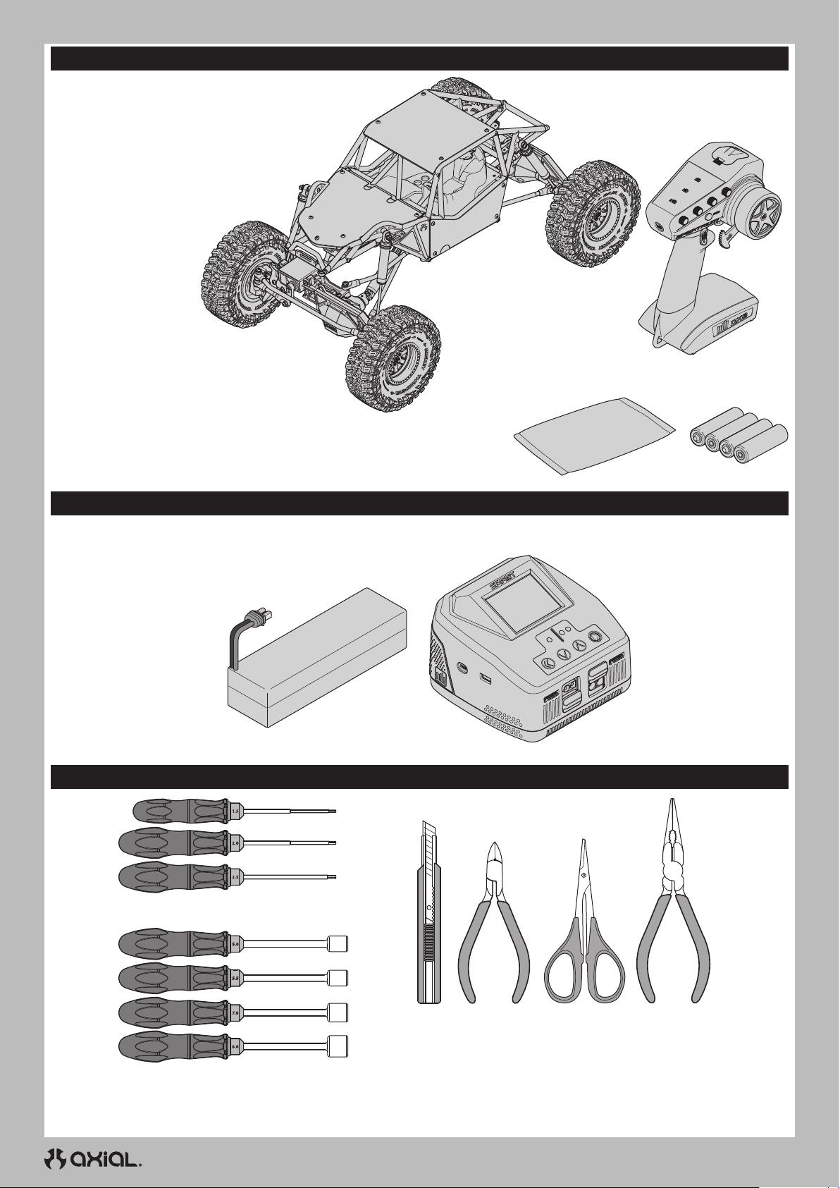
IT
CONTENUTO DELLA SCATOLA
• Trasmittente Spektrum DX3 Smart con volantino con sterzo a pollice
(SPMR2340T)
• Gilamon 2.2 4WD Trail Buggy RTR
- Motore elettrico a spazzole Boulder 550, 21T (AXI-2156)
- Servo S682 20 kg ingranaggio acciaio 25T (SPMS682)
- Servo SX117AX micro cassa/ingranaggio metallo,
Cavo da 250 mm (SPMSSX117AX)
- Ricevitore Sport SR515 DSMR
5 canali (SPMSR515)
- ESC Firma 70 A Smart WP a spazzole
(SPMXSE1070)
• Batterie alcaline AA (4)
• Busta per componenti • (4) Batterie
alcaline AA
APPARECCHIATURE NECESSARIE
• Batteria LiPo 2-3S
(Connettore IC3 richiesto)
STRUMENTI CONSIGLIATI
• Cacciaviti esagonali: (1,5, 2,0, 2,5 mm)
• Caricabatterie compatibile con la
batteria scelta per il veicolo
• Avvitadadi (5,0, 5,5, 7,0, 8,0mm)
• Taglierino • Tronchesino • Forbici
curve
46
• Pinze a becchi
lunghi
Page 47
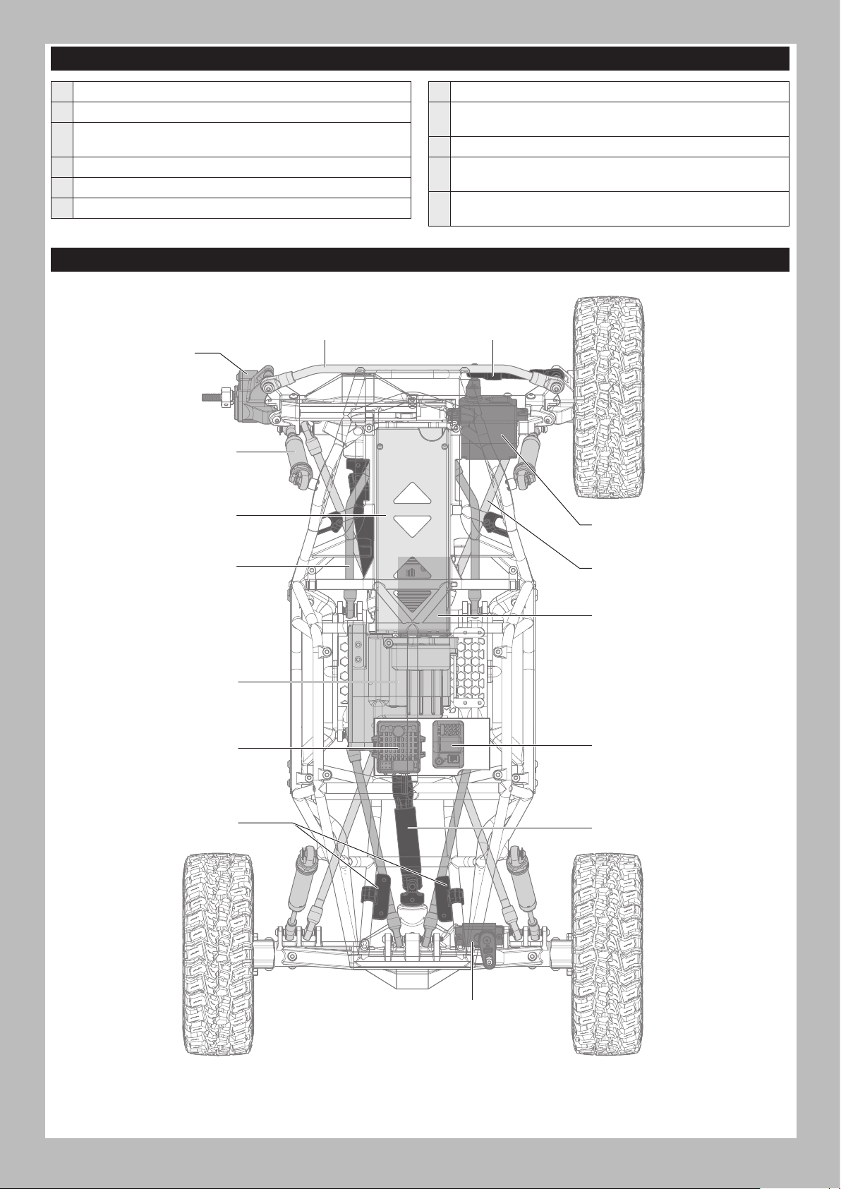
LISTA DI CONTROLLO PRE-UTILIZZO
IT
Leggere il manuale
Acquisire familiarità con il veicolo e i suoi componenti
Verificare che tutte le viti, in particolare le viti di fissaggio
dell’albero di trasmissione, siano state ben serrate in fabbrica
Caricare la batteria del veicolo
Installare 4 batterie AA nella trasmittente
Accendere la trasmittente
PARTI DEL VEICOLO
Tirante sterzo
Fuso a snodo
Ammortizzatore
Installare la batteria del veicolo nel modello
Verificare il corretto funzionamento dell’acceleratore e dello
sterzo
Provare la portata del radiocomando
Ora è possibile pilotare il veicolo e mettersi alla prova: BUON
DIVERTIMENTO!
Realizzare eventuali operazioni di manutenzione necessarie sul
veicolo
Tirante longitudinale
Vassoio portabatteria
Barra superiore 4-link
Trasmissione
Regolatore elettronico di
velocità (ESC)/ ricevitore
Luce Rock LED regolabile
Servo sterzo
Barra inferiore 4-link
Motore
Ricevitore
Albero di trasmissione
47
Servo ASD
Page 48
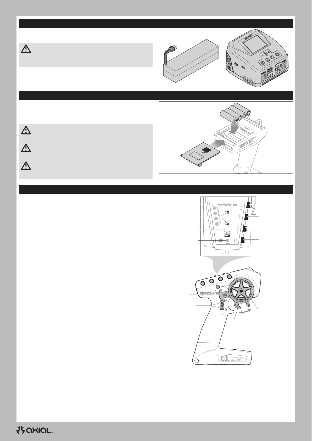
IT
CARICARE LA BATTERIA DEL VEICOLO
Seguire le istruzioni del produttore affinché il caricabatterie carichi
correttamente la batteria del veicolo.
ATTENZIONE: utilizzare esclusivamente caricabatterie
progettati per la ricarica del tipo di batteria scelto. Utilizzando
un caricabatterie errato o con impostazioni inadeguate, la batteria
potrebbe prendere fuoco o esplodere.
INSTALLARE LE BATTERIE DEL TRASMETTITORE
Per questo trasmettitore servono 4 pile AA.
1. Togliere il coperchio del portapile dal trasmettitore.
2. Inserire le pile come illustrato.
3. Rimettere a posto il coperchio del portapile.
ATTENZIONE: Non rimuovere mai le batterie dal
trasmettitore mentre il modello è acceso. Una perdita di
controllo del modello, danni o lesioni potrebbe verifi care.
ATTENZIONE: se si usano anche le batterie ricaricabili, si
raccomanda di caricare solo queste. È pericoloso caricare le
pile a secco perché potrebbero esplodere causando lesioni e/o danni.
ATTENZIONE: se le batterie vengono sostituite con tipi non
adatti, potrebbero esplodere. Le batterie si devono smaltire
nel modo corretto secondo le disposizioni locali.
FUNZIONI DELLA TRASMITTENTE
Bloccaggio ruota posteriore destra (funzione ASD)
A.
Bloccaggio ruota posteriore sinistra (funzione ASD)
B.
GAS/FRENO
C.
VOLANTINO STERZO
D.
RATEO STERZO
E.
Regola il fine corsa dello sterzo
RATEO FRENO
F.
Regola il fine corsa del freno.
TRIM STERZO
G.
Regola il punto centrale dello sterzo. Il trim dello sterzo è solitamente
regolato fino a ottenere la marcia del veicolo in linea retta.
TRIM GAS
H.
Regola il punto neutro del gas
INDICATORE DI LIVELLO DELLA BATTERIA SMART
I.
INVERSIONE CORSA SERVO
J.
Per invertire i canale di gas (TH) o sterzo (ST), impostare
il corrispondente interruttore su “N” per normale,
“R” per inversione.
LIMITE GAS
K.
Limita la potenza del motore al 50/75/100%
Selezionare 50% o 75% per i piloti meno esperti e quando
si pilota il modello in spazi ridotti.
LED ON/OFF
L.
• Luci rosse fisse: connessione radio presente e carica della
batteria adeguata
• Luci rosse lampeggianti: la tensione della batteria è
eccessivamente bassa. Sostituire le batterie
PULSANTE DI ACCENSIONE
M.
TASTO DI BINDING
N.
I
J
K
L
M
N
A/B
C
H
G
F
E
D
48
Page 49
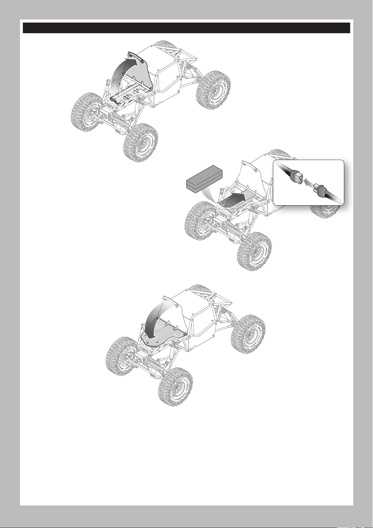
INSTALLARE LA BATTERIA DEL VEICOLO
1. Tirare verso l’alto da sotto la barra anteriore
del cofano per accedere al vano batteria.
2. Installare la batteria consigliata nel vano batterie con i cavi di
alimentazione rivolti in avanti.
3. Collegare il cavo della batteria al connettore dell’ESC
prestando attenzione alla polarità.
4. Fissare la batteria nel suo vano con la fascetta a strappo.
CONSIGLIO: avvolgere il cavo di alimentazione nella
fascetta a strappo per evitare che possa muoversi.
IT
5. Premere la parte anteriore del cofano verso il basso fino a farlo
scattare saldamente in posizione su entrambi gli angoli anteriori.
49
Page 50
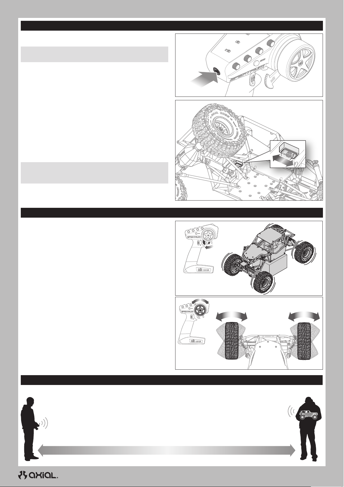
IT
ACCENSIONE E SPEGNIMENTO
ACCENSIONE
1. Accendere la trasmittente.
AVVISO: accendere sempre la trasmittente prima di accendere il
veicolo.
2. Accendere il veicolo facendo scorrere l’interruttore verso il retro
del veicolo.
SPEGNIMENTO
1. Spegnere il veicolo facendo scorrere l’interruttore verso il muso
del veicolo.
AVVISO: spegnere sempre prima il veicolo e solo dopo la
trasmittente. Spegnendo per prima la trasmittente si rischia di
perdere il controllo del veicolo.
2. Spegnere la trasmittente.
3. Scollegare la batteria dall’ESC.
4. Rimuovere la batteria dal veicolo per caricarla o conservarla.
Power
PROVA DI CONTROLLO
Provare i comandi mantenendo il modello con le ruote sollevate da
terra.
• Per far girare le ruote in avanti, premere il grilletto.
IMPORTANTE: con il rapporto di trasmissione standard l’assale
posteriore è in “underdrive”. Le ruote posteriori ruotano più
lentamente delle ruote anteriori.
• Per invertire la rotazione delle ruote, attendere che si fermino, quindi
spingere il grilletto in avanti.
• Se le ruote girano dopo aver acceso il veicolo, regolare la manopola
TH TRIM finché non ruotano più senza premere l’acceleratore.
• Ruotare il volantino della trasmittente a sinistra e a destra,
controllando che le ruote girino nella direzione corrispondente al
comando inviato.
Posizionare il veicolo a terra e accelerare leggermente:
• Quando il veicolo avanza, deve mantenersi in linea retta in assenza
di intervento sul comando dello sterzo. In caso contrario, regolare la
manopola di ST TRIM a sinistra o a destra fino a portare il veicolo in
linea retta senza dover correggere con il volantino.
PROVARE LA PORTATA DEL RADIOCOMANDO
È opportuno testare il radiocomando prima di azionare il veicolo per garantirne il corretto funzionamento e una buona portata.
1. Accendere la trasmittente.
2. Collegare la batteria nel veicolo.
3. Chiedere a un’altra persona di reggere il veicolo tenendo mani e lembi di vestiario non aderenti lontano
delle parti mobili.
4. Allontanarsi fino a raggiungere la distanza massima di funzionamento pianificata dal veicolo.
5. Girare il volantino dello sterzo da un lato e dall’altro e azionare l’acceleratore, avanti e indietro, per verificare la
presenza di eventuali comportamenti anomali.
6. In tal caso, NON utilizzare il veicolo. Chiamare il centro assistenza per ricevere aiuto.
50
Page 51
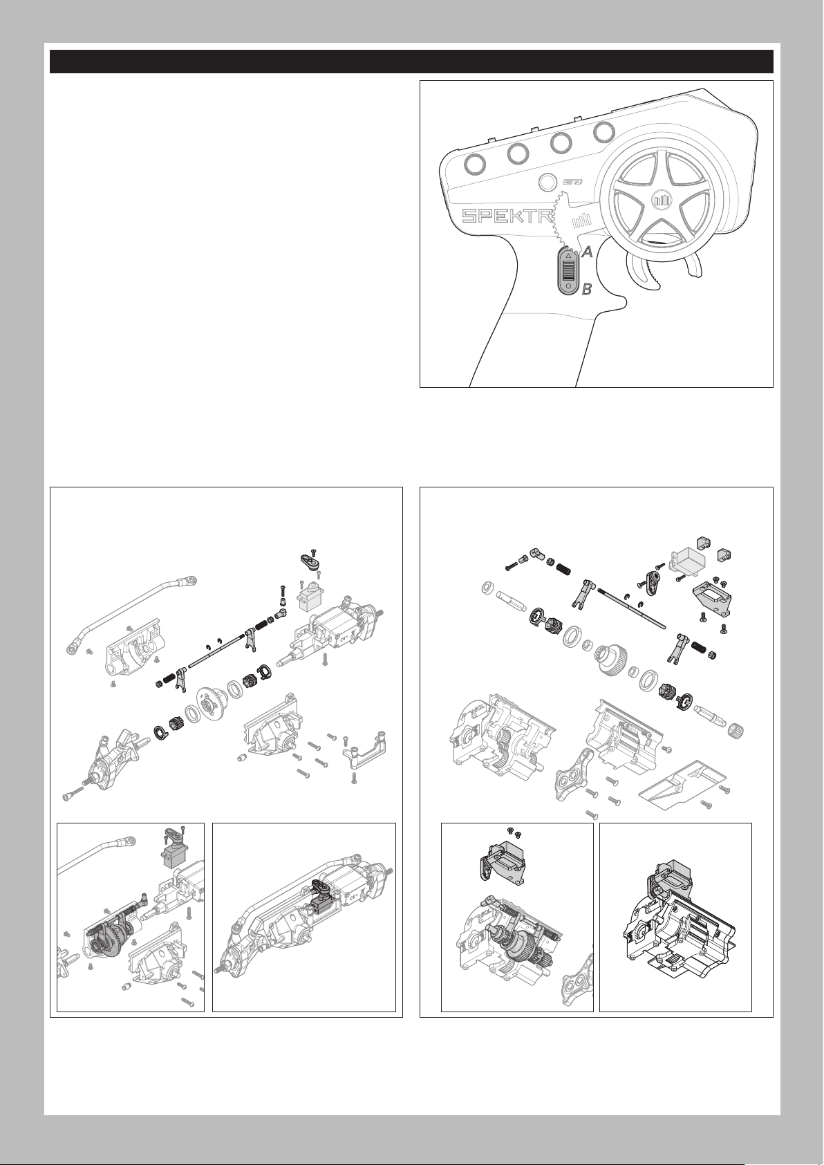
AXIAL SELECTABLE DRIVE (ASD)
L’asse posteriore del veicolo monta preinstallato l’Axial Selectable
Drive (ASD). Con l’ASD è possibile bloccare la ruota posteriore sinistra
o quella destra, consentendo così al veicolo curve molto strette
ruotando attorno alla ruota “bloccata”.
Per attivare l’ASD:
1. Tenere premuto il pulsante A o B.
• A innesta il bloccaggio della ruota sinistra
• B innesta il bloccaggio della ruota destra
2. Ruotare il volantino e dare lentamente o in modo intermittente gas
per ruotare il veicolo attorno alla ruota bloccata.
CONSIGLIO: girando il volantino nella direzione della ruota
bloccata si stringe la curva in quella direzione.
Ruotando il volantino in direzione opposta a quella della ruota
bloccata si induce uno scorrimento lento rispetto alla ruota
bloccata.
3. Rilasciare il pulsante A o B e l’acceleratore per “sbloccare” la
ruota.
CONSIGLIO: potrebbe essere necessario spingere
leggermente la retromarcia per sbloccare l’ASD.
FUNZIONI ASD AGGIUNTIVE (OPZIONALI)
Con l’acquisto di un servo aggiuntivo e del set di parti ASD: AXP8 (AXI-
2191), l’Axial Selectable Drive può essere aggiunto anche all’assale
anteriore o alla trasmissione, o a entrambi, con l’acquisto di due set e
servo.
IMPORTANTE: il controllo delle funzioni opzionali aggiuntive
richiede una trasmittente con più di tre canali, come la trasmittente
Spektrum DX6 Rugged 6 canali DSMR (SPMR6215).
IT
INSTALLAZIONE ASD SU ASSALE ANTERIORE (OPZIONALE)
Per abilitare il bloccaggio della ruota anteriore destra o sinistra
Servo non incluso (consigliato SPMSSX117AX)
INSTALLAZIONE ASD SULLA TRASMISSIONE (OPZIONALE)
Per abilitare la funzione sugli assali anteriore e posteriore
Servo non incluso (consigliato SPMSSX117AX)
51
Page 52
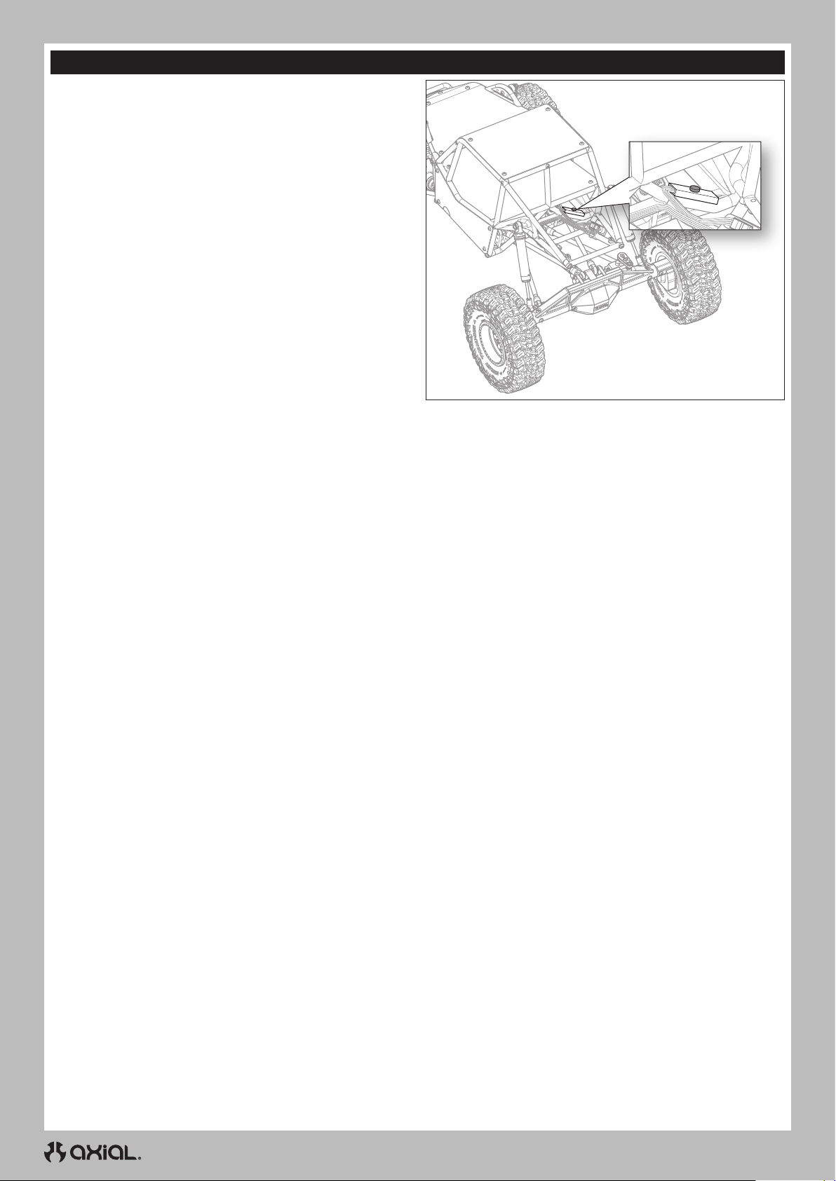
IT
LUCI ROCK LED
Il veicolo è fornito con luci rock LED RGB selezionabili a colori
installate.
Per azionare le luci:
1. Accendere il modello.
2. Premere il pulsante di controllo delle luci, che si trova nella parte
posteriore della gabbia di protezione, come mostrato. Il LED si
accende in rosso con la prima pressione.
3. Scorrere i sette colori disponibili premendo ripetutamente il
pulsante di controllo fino a trovare il colore desiderato.
4. Spegnere le luci scorrendo i colori con il pulsante di controllo fino
a quando le luci non si spengono.
SEQUENZA LED:
1. Rosso
2. Verde
3. Blu
4. Giallo
5. Viola
6. Verde acqua
7. Bianco
8. Spento
52
Page 53
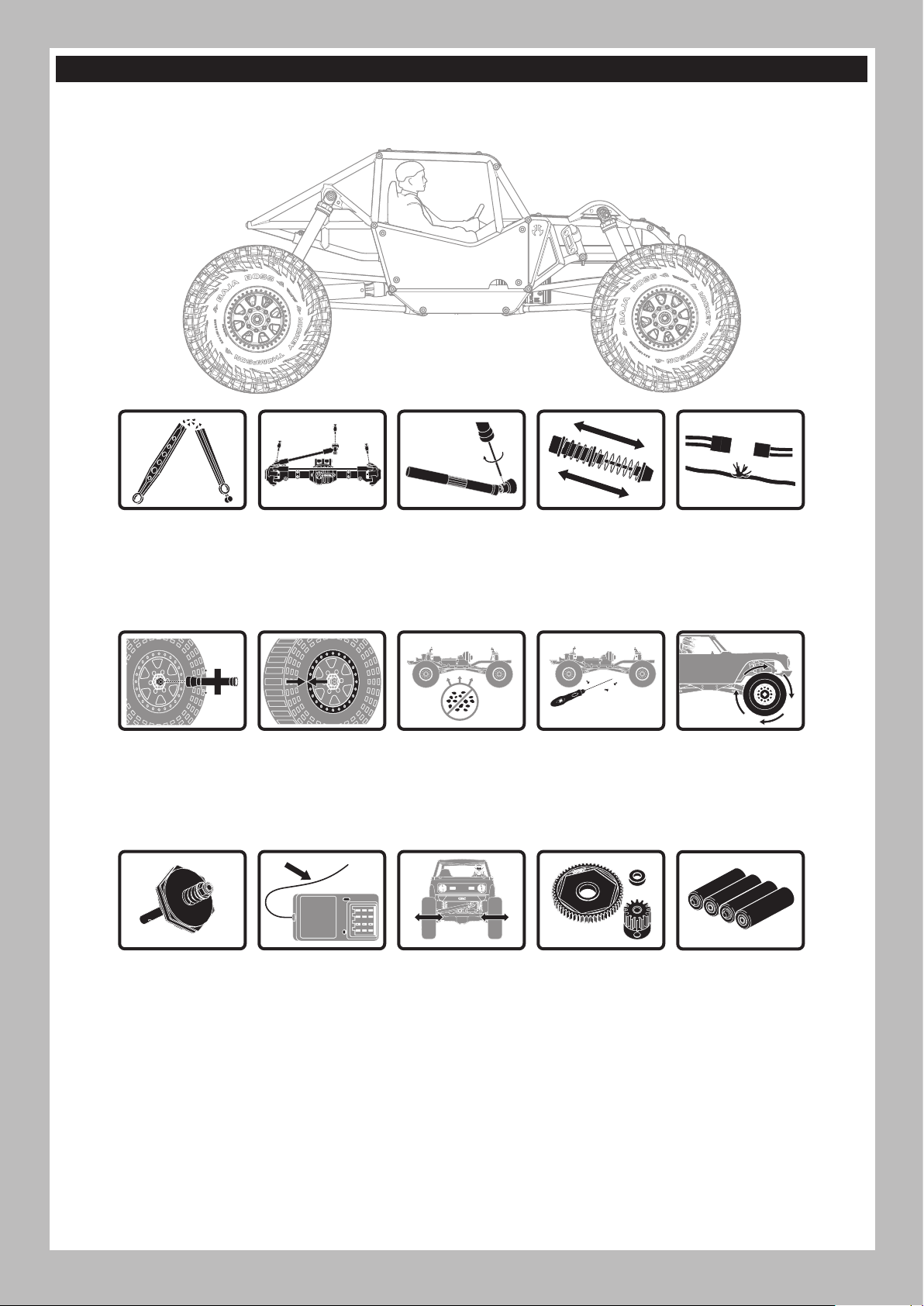
MANUTENZIONE DEL VEICOLO
Proprio come una macchina o un pick-up a grandezza naturale, il modello RC deve essere sottoposto a regolare manutenzione per garantire
prestazioni ottimali. La manutenzione preventiva consente anche di evitare inutili rotture dei componenti che potrebbero richiedere riparazioni
costose. Di seguito vengono forniti alcuni suggerimenti per una manutenzione adeguata del veicolo.
IT
Sostituire eventuali
componenti
visibilmente piegati o
danneggiati
Verificare che i dadi
delle ruote siano ben
serrati
Se presente, verificare
il funzionamento
della frizione
antisaltellamento
Verificare l’usura dei
giunti sferici delle
bielle dello sterzo
e delle sospensioni
(sostituirli se
necessario)
Assicurarsi che i
talloni delle ruote
aderiscano ancora
perfettamente lungo
tutta la circonferenza
del cerchione
Verificare che
l’antenna del
ricevitore non sia
danneggiata
Verificare le viti di
fissaggio dell’albero
di trasmissione
e applicare del
frenafiletti se
necessario
Mantenere il telaio
privo di sporco o
detriti
Verificare che lo
sterzo si muova
liberamente
Verificare che gli
ammortizzatori
operino in modo fluido
e regolare
Verificare la presenza
di viti allentate sul
telaio, in particolare
le viti di blocco dello
snodo, del mozzo
centrale e dell’assale
Ispezionare la corona
e il pignone per
verificare la presenza
di danni
Verificare la presenza
di parti allentate o cavi
danneggiati
Verificare che la
trasmissione operi in
modo fluido e senza
impedimenti
Sostituire le batterie
della trasmittente
quando indicato dalla
trasmittente, come
descritto al paragrafo
‘Funzioni della
trasmittente’
53
Page 54
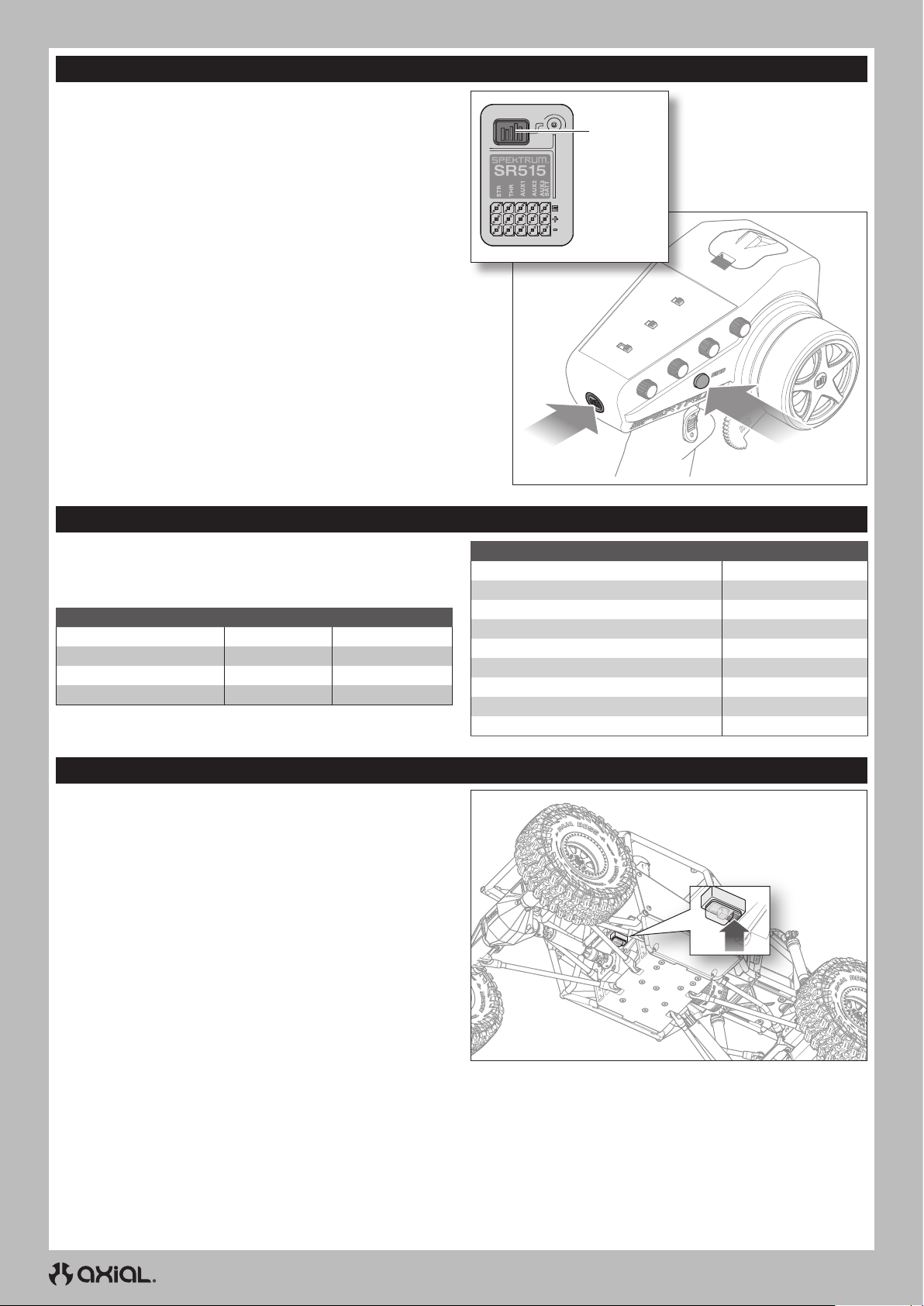
IT
CONNESSIONE (BINDING)
Il binding è la procedura di programmazione con la quale il ricevitore
impara a riconoscere il codice identificativo universalmente univoco
GUID (Globally Unique Identifier) della trasmittente cui viene associato.
Trasmittente e ricevitore sono connessi in fabbrica. Se è necessario
ripetere il binding, seguire le istruzioni riportate di seguito.
1. Collegare una batteria completamente carico all’ESC/ricevitore.
2. Tenere premuto il tasto di binding sul ricevitore.
3. Accendere il ricevitore. Il LED rosso lampeggia, a indicare che il
ricevitore è in modalità di binding.
4. Rilasciare il tasto di binding.
5. Con il grilletto del gas su neutro, premere e tenere premuto il tasto
di binding della trasmittente mentre questa viene accesa in modo
da impostare la trasmittente in modalità di binding.
IMPORTANTE: Il comando del gas deve essere in posizione
neutra per impostare i failsafe.
6. Il processo di binding è completo quando il LED verde sul
ricevitore rimane acceso fisso.
Il binding va ripetuto quando è necessario modificare le posizioni di
failsafe; per esempio, quando si invertono i comandi di gas o sterzo.
Tasto di
binding
INDICATORE LED E SUONI MOTORE
Quando l’ESC viene accesso, il LED lampeggia e il motore emette
una serie di bip per indicare il suo stato. Prima mostrerà la modalità
selezionata della batteria, poi l’impostazione del freno motore e infine
darà conferma che è pronto a funzionare.
Caratteristiche Stato LED Suoni motore
Batteria Ni-MH/Ni-CD 1 lampeggio 1 bip breve
Batteria Li-Po 2S 2 lampeggi 2 bip brevi
Batteria Li-Po v 3 lampeggi 3 bip brevi
Predisposizione per ESC 1 lampeggio lungo 1 bip lungo
CALIBRAZIONE DI ESC E TRASMITTENTE
È importante calibrare l’ESC alla trasmittente in modo da far
corrispondere l’ESC all’intervallo dell’acceleratore sulla trasmittente.
La mancata calibrazione tra ESC e radiocomando ne pregiudica il
corretto funzionamento. Impostare il failsafe sulla radio in posizione
neutra per garantire l’arresto del motore in caso di perdita del segnale.
1. Accendere la trasmittente.
2. Impostare il fine corsa dell’acceleratore al 100% e centrare il trim
dell’acceleratore prima di procedere con la calibrazione.
3. Collegare la batteria all’ESC.
4. Tenere premuto il pulsante di programmazione sulla cassa dello
switch e accendere l’ESC.
Il LED rosso sull’ESC lampeggia e il motore emette un segnale
acustico.
5. Rilasciare il pulsante di programmazione dopo 3 secondi.
IMPORTANTE: L’ESC entrerà in modalità di programmazione
se il pulsante di programmazione non viene rilasciato entro 3
secondi. Se l’ESC entra in modalità di programmazione, spegnere
il veicolo e tornare al punto 4.
6. Con il grilletto del gas e il trim in posizione neutra, premere e
rilasciare il pulsante di programmazione. Il LED rosso lampeggia
una volta e il motore emette 1 tono sonoro.
CONSIGLIO: i segnali acustici dal motore potrebbero risultare
difficili da udire. Usare come riferimento lo stato del LED per
verificare le impostazioni.
7. Premere completamente il grilletto del gas. Premere e rilasciare il
pulsante di programmazione. Il LED rosso lampeggia due volte e il
motore emette 2 toni sonori.
Pulsante di
accensione
Durante l’utilizzo Stato LED
Stop OFF
Gas parziale avanti Lampeggiante
Gas al massimo Fisso
Gas parziale indietro Lampeggiante
Gas al massimo Fisso
Freno parziale Lampeggiante
Freno pieno Fisso
Tensione batteria bassa Lampeggiante
Surriscaldamento Lampeggiante
8. Spingere il grilletto dell’acceleratore tutto indietro. Premere e
rilasciare il pulsante di programmazione. Il LED rosso lampeggia 3
volte e il motore emette 3 toni sonori.
9. Spegnere il sistema con il pulsante ON/OFF.
10. Accendere il sistema con il pulsante ON/OFF. Il sistema è pronto
per l’uso
Tasto di binding
54
Page 55

GUIDA ALLA RISOLUZIONE DEI PROBLEMI
PROBLEMA POSSIBILE CAUSA SOLUZIONE
Trasmittente e ricevitore sono troppo
vicini tra loro
Si è in prossimità di oggetti metallici Allontanarsi dagli oggetti metallici
Il sistema non si collega
Il ricevitore va in modalità failsafe a breve
distanza dal trasmettitore
Il ricevitore smette di rispondere durante
il funzionamento
Il veicolo non si muove
Perdita del controllo del veicolo
La funzione sterzo e/o acceleratore è
invertita
ESC ON - No azionamento motore, bip o
LED
Motore - Si arresta e il LED lampeggia
Motore - Accelera in modo irregolare
Motore - Risposta irregolare al comando
del gas
Motore - Rallenta ma non si ferma Calibrazione trasmittente/ESC errata
Servo di sterzata - In funzione; il motore
non gira
Sterzo/motore - Non funzionanti
Veicolo - Non raggiunge la velocità max
Ricevitore associato a un diverso
modello di memoria
La trasmittente è stata impostata
in modalità di binding e non è più
associata al ricevitore
Controllare che l’antenna del ricevitore
sia integra
Bassa tensione dalla batteria del
ricevitore. Se la tensione è bassa, la
batteria può scendere per un istante
sotto i 3,5 V, provocando uno sbalzo di
tensione del ricevitore e successiva
riconnessione
Fili o connettori tra batteria e ricevitore
allentati o danneggiati
Le batterie non sono state installate
correttamente nella trasmittente
Batteria scarica o assente nel veicolo Installare una batteria appena ricaricata sul veicolo
Motore danneggiato Sostituire il motore
Cavi danneggiati o rotti Sostituire i cavi danneggiati
L’ESC viene spento dal circuito di
protezione termica
Antenna posizionata in modo errato
Batterie scariche o assenti nel veicolo
Posizione neutra o del trim errata Regolare il trim dello sterzo
Ricevitore e/o batteria non collegati
correttamente
La corsa del servo è invertita a livello
della trasmittente
I cavi del motore non sono collegati
correttamente
Problema di connessione/batteria
ESC o interruttore danneggiati Riparare/sostituire ESC/interruttore ESC
Motore danneggiato Riparare/sostituire
Protezione da bassa tensione Se il LED dell’ESC lampeggia, ricaricare/sostituire la batteria
Protezione da surriscaldamento
Problema con la batteria Riparare il cablaggio danneggiato/sostituire la batteria
Combinazione pignone e corona errata Regolare/sostituire
Motore danneggiato o usurato Riparare/sostituire il motore
ESC/motore danneggiato Riparare/sostituire il cablaggio o il motore/ESC
Motore danneggiato
Calibrazione trasmittente/ESC errata
Tensione batteria bassa Ricaricare/sostituire
Modello memoria selezionato nella
trasmittente errato
Ricevitore non associato alla
trasmittente
Problema con la batteria Ricaricare/sostituire
Calibrazione trasmittente/ESC errata
IT
Spostare la trasmittente a 2,5-4 m dal ricevitore
Assicurarsi che nella trasmittente sia attivo il modello di
memoria corretto
Ripetere il binding tra trasmittente e ricevitore e poi
ricalibrazione
L’antenna deve essere in posizione protetta e quanto più in
alto possibile
Sostituire il ricevitore o contattare il supporto tecnico Horizon
Caricare la batteria del veicolo o del ricevitore. I ricevitori
Spektrum necessitano di almeno 3,5 V per funzionare
Controllare i fili e il collegamento tra batteria e ricevitore.
Riparare o sostituire i fili e/o i connettori
Assicurarsi che le batterie della trasmittente siano installate
correttamente
Lasciare raffreddare completamente l’ESC
Assicurarsi che l’antenna della trasmittente non sia
bloccata e che l’antenna del ricevitore sia posizionata
correttamente
Installare una batteria appena ricaricata sul veicolo e
batteria nuove sulla trasmittente
Verificare tutti i collegamenti del ricevitore e della batteria
Mettere in posizione corretta l’interruttore d’inversione
della corsa del servo sulla trasmittente
Verificare che tutti i cavi del motore abbiano polarità
corretta e siano ben collegati
Ricaricare/sostituire la batteria. Controllare tutte le
connessioni
Se il LED lampeggia, far raffreddare il motore/ESC, cambiare
impostazioni o la combinazione pignone e corona per
evitare il surriscaldamento
Regolare la corsa e le altre impostazioni del comando
del gas sulla trasmittente/ESC. Ripetere la procedura di
calibrazione dell’ESC
Provare il motore separatamente dal sistema del veicolo,
riparare/sostituire come necessario
Regolare la corsa e le altre impostazioni del comando
del gas sulla trasmittente/ESC. Ripetere la procedura di
calibrazione dell’ESC
Selezionare sulla trasmittente le impostazioni modello
corrette; vedere il manuale di ricevitore e/o trasmittente
Associare trasmittente e ricevitore; vedere il manuale di
ricevitore e/o trasmittente
Regolare la corsa e le altre impostazioni del comando
del gas sulla trasmittente/ESC. Ripetere la procedura di
calibrazione dell’ESC
55
Page 56

IT
GARANZIA
Periodo di garanzia
Garanzia esclusiva - Horizon Hobby, LLC (Horizon) garantisce che
il prodotto acquistato (il “Prodotto”) sarà privo di difetti relativi ai
materiali e di eventuali errori di montaggio alla data di acquisto. Il
periodo di garanzia è conforme alle disposizioni legali del paese nel
quale il prodotto è stato acquistato. Tale periodo di garanzia ammonta
a 6 mesi e si estende ad altri 18 mesi dopo tale termine.
Limiti della garanzia
(a) La garanzia è limitata all’acquirente originale (Acquirente) e
non è cedibile a terzi. L’acquirente ha il diritto a far riparare o a
far sostituire la merce durante il periodo di questa garanzia. La
garanzia copre solo quei prodotti acquistati presso un rivenditore
autorizzato Horizon. Altre transazioni di terze parti non sono
coperte da questa garanzia. La prova di acquisto è necessaria per
far valere il diritto di garanzia. Inoltre, Horizon si riserva il diritto
di cambiare o modificare i termini di questa garanzia senza alcun
preavviso e di escludere tutte le altre garanzie già esistenti.
(b) Horizon non si assume alcuna garanzia per la disponibilità del
prodotto, per l’adeguatezza o l’idoneità del prodotto a particolari
previsti dall’utente. È sola responsabilità dell’acquirente il fatto di
verificare se il prodotto è adatto agli scopi da lui previsti.
(c) Richiesta dell’acquirente – spetta soltanto a Horizon, a propria
discrezione riparare o sostituire qualsiasi prodotto considerato
difettoso e che rientra nei termini di garanzia. Queste sono le
uniche rivalse a cui l’acquirente si può appellare, se un prodotto è
difettoso.
Horizon si riserva il diritto di controllare qualsiasi componente utilizzato
che viene coinvolto nella rivalsa di garanzia. Le decisioni relative alla
sostituzione o alla riparazione sono a discrezione di Horizon. Questa
garanzia non copre dei danni superficiali o danni per cause di forza
maggiore, uso errato del prodotto, un utilizzo che viola qualsiasi legge,
regolamentazione o disposizione applicabile, negligenza, uso ai fini
commerciali, o una qualsiasi modifica a qualsiasi parte del prodotto.
Questa garanzia non copre danni dovuti ad un’installazione errata,
ad un funzionamento errato, ad una manutenzione o un tentativo
di riparazione non idonei a cura di soggetti diversi da Horizon.
La restituzione del prodotto a cura dell’acquirente, o da un suo
rappresentante, deve essere approvata per iscritto dalla Horizon.
Limiti di danno
Horizon non si riterrà responsabile per danni speciali, diretti, indiretti o
consequenziali; perdita di profitto o di produzione; perdita commerciale
connessa al prodotto, indipendentemente dal fatto che la richiesta
si basa su un contratto o sulla garanzia. Inoltre la responsabilità
di Horizon non supera mai in nessun caso il prezzo di acquisto del
prodotto per il quale si chiede la responsabilità. Horizon non ha alcun
controllo sul montaggio, sull’utilizzo o sulla manutenzione del prodotto
o di combinazioni di vari prodotti. Quindi Horizon non accetta nessuna
responsabilità per danni o lesioni derivanti da tali circostanze. Con
l’utilizzo e il montaggio del prodotto l’utente acconsente a tutte le
condizioni, limitazioni e riserve di garanzia citate in questa sede.
Qualora l’utente non fosse pronto ad assumersi tale responsabilità
associata all’uso del prodotto, si suggerisce di restituire il prodotto
intatto, mai usato e immediatamente presso il venditore.
Indicazioni di sicurezza
Questo è un prodotto sofisticato di hobbistica e non è un giocattolo.
Esso deve essere manipolato con cautela, con giudizio e richiede
delle conoscenze basilari di meccanica e delle facoltà mentali di base.
Se il prodotto non verrà manipolato in maniera sicura e responsabile
potrebbero risultare delle lesioni, dei gravi danni a persone, al
prodotto o all’ambiente circostante. Questo prodotto non è concepito
per essere usato dai bambini senza una diretta supervisione di un
adulto. Il manuale del prodotto contiene le istruzioni di sicurezza, di
funzionamento e di manutenzione del prodotto stesso. È fondamentale
leggere e seguire tutte le istruzioni e le avvertenze nel manuale prima
di mettere in funzione il prodotto. Solo così si eviterà un utilizzo errato
e si preverranno incidenti, lesioni o danni.
Domande, assistenza e riparazioni
Il vostro negozio locale e/o luogo di acquisto non possono fornire
garanzie di assistenza o riparazione senza previo colloquio con Horizon.
Questo vale anche per le riparazioni in garanzia. Quindi in tale casi
bisogna interpellare un rivenditore, che si metterà in contatto subito con
Horizon per prendere una decisione che vi possa aiutare nel più breve
tempo possibile.
Manutenzione e riparazione
Se il prodotto deve essere ispezionato o riparato, si prega di rivolgersi ad un
rivenditore specializzato o direttamente ad Horizon. Il prodotto deve essere
imballato con cura. Bisogna far notare che i box originali solitamente
non sono adatti per effettuare una spedizione senza subire alcun
danno. Bisogna effettuare una spedizione via corriere che fornisce una
tracciabilità e un’assicurazione, in quanto Horizon non si assume alcuna
responsabilità in relazione alla spedizione del prodotto. Inserire il prodotto
in una busta assieme ad una descrizione dettagliata degli errori e ad una
lista di tutti i singoli componenti spediti. Inoltre abbiamo bisogno di un
indirizzo completo, di un numero di telefono per chiedere ulteriori domande
e di un indirizzo e-mail.
Garanzia e riparazione
Le richieste in garanzia verranno elaborate solo se è presente
una prova d’acquisto in originale proveniente da un rivenditore
specializzato autorizzato, nella quale è ben visibile la data di acquisto.
Se la garanzia viene confermata, allora il prodotto verrà riparato o
sostituito. Questa decisione spetta esclusivamente a Horizon Hobby.
Riparazioni a pagamento
Se bisogna effettuare una riparazione a pagamento, effettueremo un
preventivo che verrà inoltrato al vostro rivenditore. La riparazione
verrà effettuata dopo l’autorizzazione da parte del vostro rivenditore.
La somma per la riparazione dovrà essere pagata al vostro
rivenditore. Le riparazioni a pagamento avranno un costo minimo di
30 minuti di lavoro e in fattura includeranno le spese di restituzione.
Qualsiasi riparazione non pagata e non richiesta entro 90 giorni verrà
considerata abbandonata e verrà gestita di conseguenza.
ATTENZIONE: Le riparazioni a pagamento sono disponibili solo
sull’elettronica e sui motori. Le riparazioni a livello meccanico,
soprattutto per gli elicotteri e le vetture RC, sono molto costose e
devono essere effettuate autonomamente dall’acquirente.
10/15
GARANZIA E ASSISTENZA - INFORMAZIONI PER I CONTATTI
Stato di acquisto Horizon Hobby Telefono/Indirizzo e-mail Indirizzo
Unione Europea
56
Hanskampring 9
D 22885 Barsbüttel, Germany
Page 57

DICHIARAZIONE DI CONFORMITÀ PER L’UNIONE EUROPEA
DICHIARAZIONE DI CONFORMITÀ UE:
Axial Gilamon Trail Buggy RTR (AXI-1207)
Con la presente, Horizon Hobby, LLC dichiara che il
dispositivo è conforme a quanto segue: Direttiva europea sulle
apparecchiature radio (RED) 2014/53/UE; Direttiva RoHS 2 2011/65 / UE;
Direttiva RoHS 3 - Modifica 2011/65 / UE allegato II 2015/863.
Il testo completo della dichiarazione di conformità UE è disponibile al
seguente indirizzo internet: https://www.horizonhobby.com/content/
support-render-compliance.
Gamma di frequenza wireless / Potenza di uscita wireless
Trasmettitore
2402.0 - 2478.0 MHz
17.7 dBm
Ricevitore
2404-2476MHz
-1.33dBm
Produttore ufficiale dell’UE:
Horizon Hobby, LLC
2904 Research Road
Champaign, IL 61822 USA
Importatore ufficiale dell’UE:
Horizon Hobby, GmbH
Hanskampring 9
22885 Barsbüttel Germany
AVVISO RAEE:
Questo dispositivo è marcato ai sensi della Direttiva
europea 2012/19/UE riguardante i rifiuti di apparecchiature
elettriche ed elettroniche (RAEE). Il simbolo indica che il
prodotto non va smaltito insieme ai rifiuti domestici. Il
prodotto deve essere consegnato agli appositi centri di
raccolta per consentirne il recupero e il riciclaggio.
IT
57
Page 58
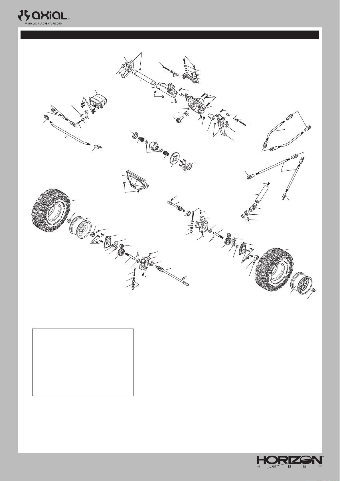
AXI-1207
AXP8 GILAMON 2.2
EXPLODED VIEWS // EXPLOSIONSZEICHNUNGEN // VUES ÉCLATÉES // VISTE ESPLOSE
FRONT AXLE
VORDERACHSE
ESSIEU AVANT
ASSALE ANTERIORE
AXIC1009
AXI-2211
AXI-2223
AXI-2211
AXIC0115
AXI-2223
SPMS682
AXI-2211
AXI235109
AXI-2211
AXI-2219
AXIC1495
AXI231056
LOSA6944
AXI-2219
TLR5900
AXI-2219
AXI-2219
TLR5900
AXI-2203
AXIC0014
AXIC1072
AXI235109
AXIC0218
AXI-2203
AXI-2211
TLR5900
LOS247001
AXI-2229
AXI-2203
AXI-2229
AXI235109
AXIC0115
AXIC0116
TLR5900
AXIC1120
AXI-2211
AXI-2211
AXIC0115
AXI-2219
AXI-2219
TLR5900
LOSA6944
AXI235110
AXI-2219
AXIC0115
AXI-2211
AXIC1495
AXI-2219
AXI-2211
AXIC1072
AXIC0014
AXI-2211
AXIC0114
AXI-2211
AXI-2221
AXI-2211
AXI-2221
AXI-2190
AXI-2230
AXIC0115
AXI-2196
AXI-2230
LOSA6940
TLR5900
AXI-2230
AXI-2228
AXI-2228
AXIC0014
AXIC1072
AXI-2211
AXI-2230
AXI-2218
LOSA6940
AXI237009
AXI-2228
AXI-2228
AXI-2211
AXIC4403
AXI-2218
AXIC4403
OPTIONAL ASD PARTS | OPTIONALE ASD-TEILE |
PIÈCES ASD EN OPTION | PARTI ASD OPZIONALI
AXI-2191
ASD Parts Set Complete: AXP8
Enables front left or right selectable drive
Kompletter ASD-Teilesatz: AXP8
Aktiviert den Antrieb vorn links oder rechts
Ensemble de pièces ASD complet: AXP8
Permet d’activer l’entraînement sélectionnable
à l’avant, à gauche ou à droite
Set parti ASD completo: AXP8
Abilita il bloccaggio della ruota anteriore
sinistra o destra
AXIC0230
AXIC1072
AXI-2211
AXI-2211
AXI-2211
AXIC0230
AXI-2226
AXIC1391
AXI-2226
AXIC4403
AXIC1391
AXIC0014
AXIC4403
AXI-2228
AXI-2228
AXI-2218
LOSA6940
AXI-2228
LOSA6940
AXI-2230
AXIC0115
AXI-2212
AXI-2228
AXI-2230
AXI-2230
AXI-2231
LOSA6940
AXI237009
AXI-2218
AXI-2211
AXI-2231
AXI-2212
AXI-2190
AXI-2196
AXI-2230
58
Page 59
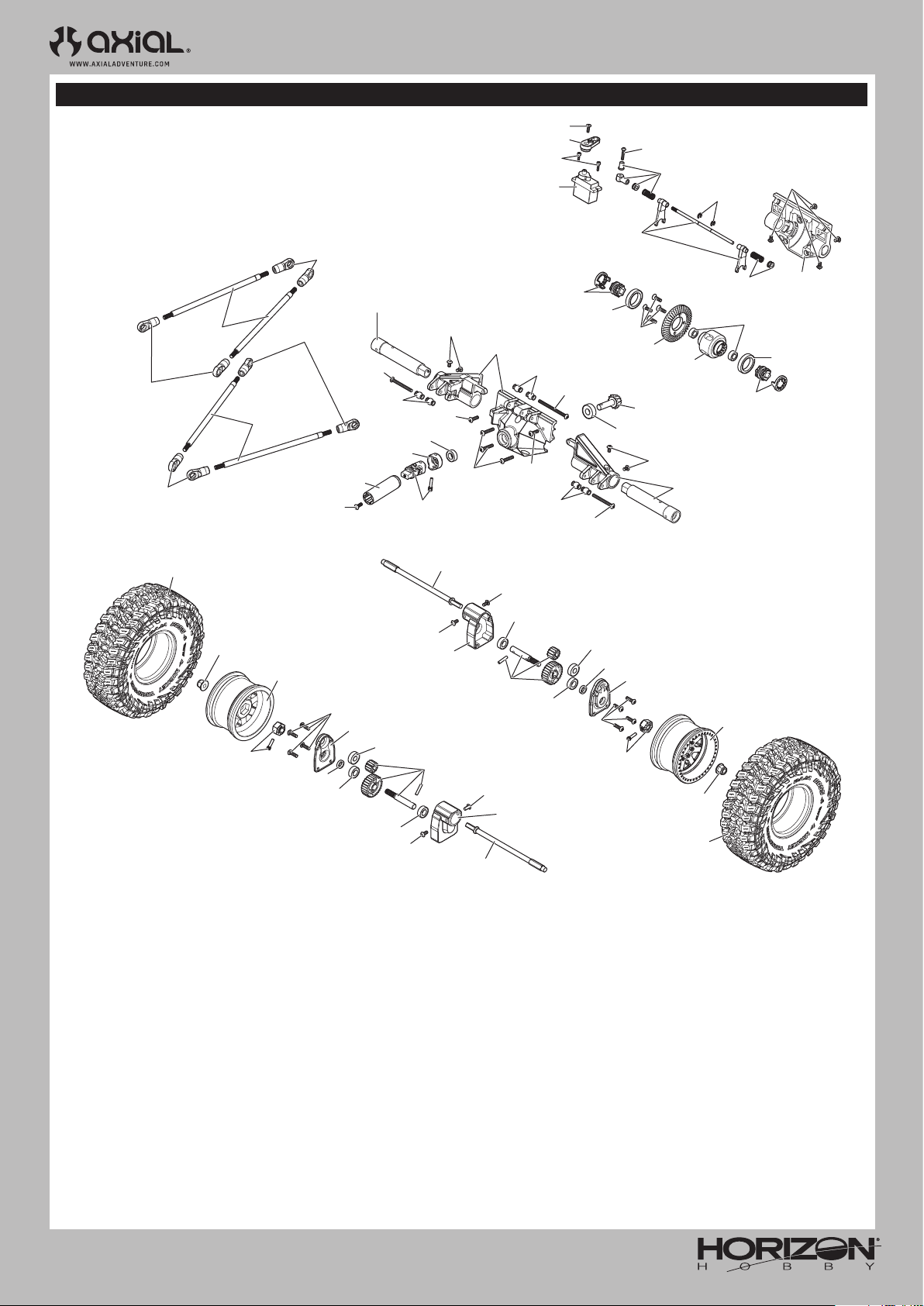
AXI-1207
AXP8 GILAMON 2.2
EXPLODED VIEWS // EXPLOSIONSZEICHNUNGEN // VUES ÉCLATÉES // VISTE ESPLOSE
REAR AXLE
HINTERACHSE
ESSIEU ARRIÈRE
ASSALE POSTERIORE
AXI-2222
AXI-2211
AXI-2211
AXI-2211
AXI-2222
AXIC0114
AXI-2211
AXI-2216
AXIC0014
AXI-2212
TLR5900
AXI-2211
AXIC0115
LOSA6940
AXI-2212
AXI235110
AXI-2231
AXI235167
AXIC3066
SPMSX117
AXI-2216
AXIC0115
AXI-2211
AXI-2193
AXI-2191
AXI-2211
TLR5907
AXIC0014
AXI-2191
LOSA6944
AXIC1120
AXI-2229
AXI-2229
LOS247001
AXIC1195
AXI-2193
AXI-2203
TLR5900
AXI-2216
AXIC0393
AXI-2193
AXI-2191
TLR5900
AXI-2216
AXIC0218
LOSA6944
AXI-2190
AXI-2230
AXI-2230
AXI-2196
AXI-2230
LOSA6940
AXIC0115
AXI-2217
LOSA6940
TLR5900
TLR5900
AXI-2217
AXI237009
AXI-2227
AXI-2228
AXI-2228
AXI-2227
TLR5900
LOSA6940
LOSA6940
TLR5900
AXI-2217
AXI237009
AXIC0115
AXI-2230
AXI-2230
AXI-2217
AXI-2196
AXI-2230
AXI-2190
59
Page 60
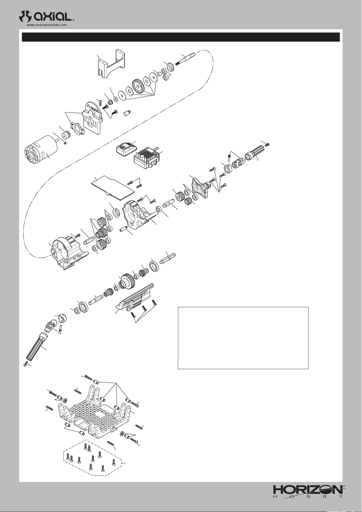
AXI-1207
AXP8 GILAMON 2.2
EXPLODED VIEWS // EXPLOSIONSZEICHNUNGEN // VUES ÉCLATÉES // VISTE ESPLOSE
TRANSMISSION
GETRIEBE
TRANSMISSION
TRASMISSIONE
AXI-2214
AXIC0725
AXIC0291
AXI-2156
AXI-2215
AXIC0115
AXI-2214
LOSA6944
LOSA6940
AXI-2212
AXI-2231
AXI-2212
AXIC0114
AXIC1045
AXIC0115
AXI-2214
AXI-2188
AXI-2215
AXI-2220
AXI-2214
AXI-2214
AXIC0221
AXIC0221
AXIC0218
AXI-2203
AXI-2214
AXIC1009
AXIC0218
AXI-2188
AXI-2203
AXIC0115
AXI-2214
AXI-2215
SPMSR515
AXIC0146
AXI-2215
LOSA6944
AXI-2215
AXI-2188
SPMXSE1070
LOSA6940
AXI-2188
AXI-2214
AXI-2215
AXIC0221
AXIC0114
AXI-2231
AXI-2212
AXI-2214
AXIC0146
AXI-2188
AXI-2215
AXIC0221
AXI-2212
OPTIONAL ASD PARTS | OPTIONALE ASD-TEILE |
PIÈCES ASD EN OPTION | PARTI ASD OPZIONALI
AXI-2191
ASD Parts Set Complete: AXP8
Enables front or rear selectable drive
Kompletter ASD-Teilesatz: AXP8
Ermöglicht die Auswahl zwischenFront- oder Heckantrieb
Ensemble de pièces ASD complet: AXP8
Permet d’activer l’entraînement sélectionnable à l’avant ou
à l’arrière
Set parti ASD completo: AXP8
Abilita il bloccaggio dell’assale anteriore o posteriore
AXI235110
AXI-2211
AXIC0186
AXI235110
AXI-2211
AXIC0186
AXI-2211
AXIC0186
AXIC0146
AXI235110
AXI-2189
AXIC0186
AXI-2211
AXI235110
60
Page 61
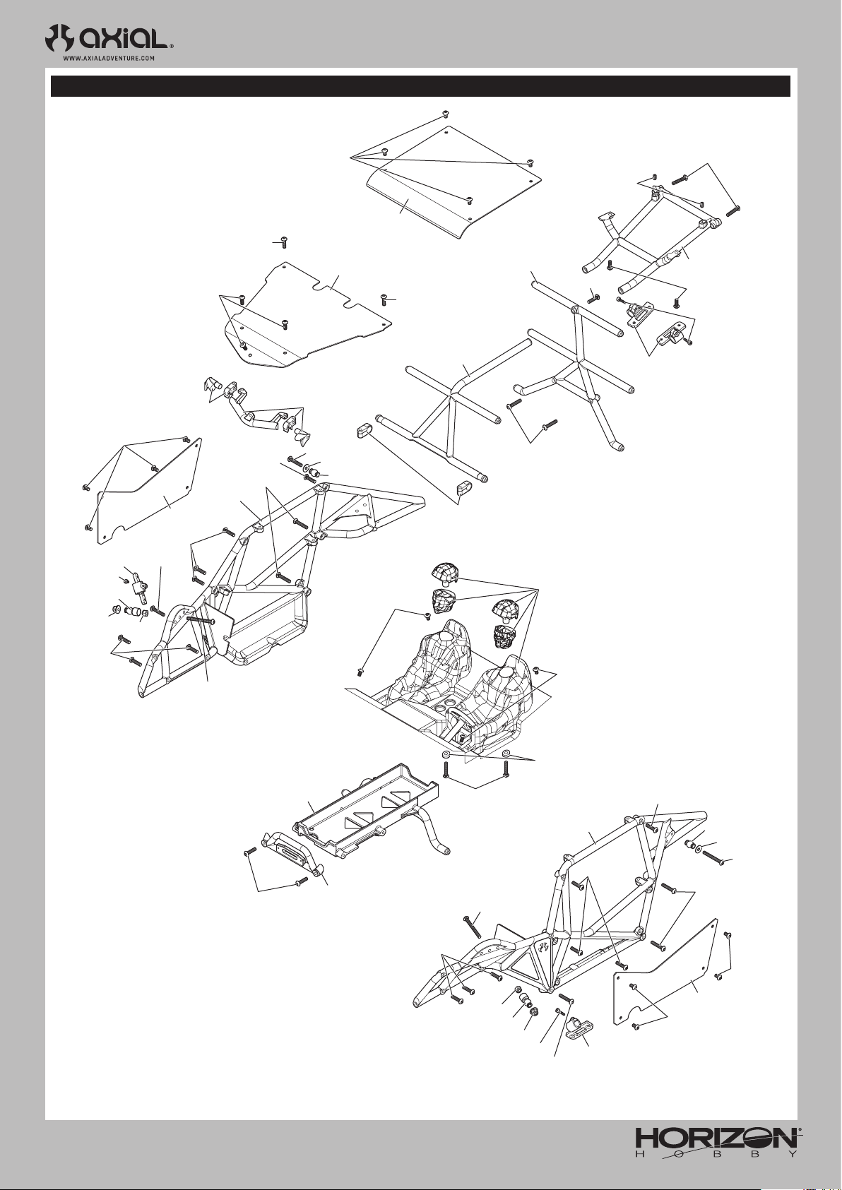
AXI-1207
AXP8 GILAMON 2.2
EXPLODED VIEWS // EXPLOSIONSZEICHNUNGEN // VUES ÉCLATÉES // VISTE ESPLOSE
CHASSIS
KAROSSERIE
CHÂSSIS
TELAIO
AXIC0114
AXIC0115
TLR5900
AXI-2187
TLR6289
AXI-2187
AXI-2220
AXI0116
AXIC0115
AXI235110
AXI-2220
AXIC0114
AXIC3066
TLR5900
AXI-2220
AXIC3066
AXI-2210
TLR245016
AXIC0116
AXIC0116
AXI235110
AXIC1053
AXI-2220
AXI-2189
AXI-2187
AXIC0014
AXIC0116
AXI235110
AXI-2220
AXIC0012
AXIC1072
AXI-2224
TLR5900
AXI-2220
AXI-2220
AXI-2220
AXI235110
AXI-2192
TLR5900
AXI-2192
AXIC0116
AXI-2189
AXI-2220
AXIC0116
61
AXI235110
AXIC0014
AXIC1053
AXI-2210
TLR245016
AXIC3066
AXI235110
AXI-2189
ACIX0116
AXI-2220
ACIX0116
AXI-2224
AXIC1072
AXIC0012
AXI235110
TLR5900
AXI-2187
TLR5900
Page 62
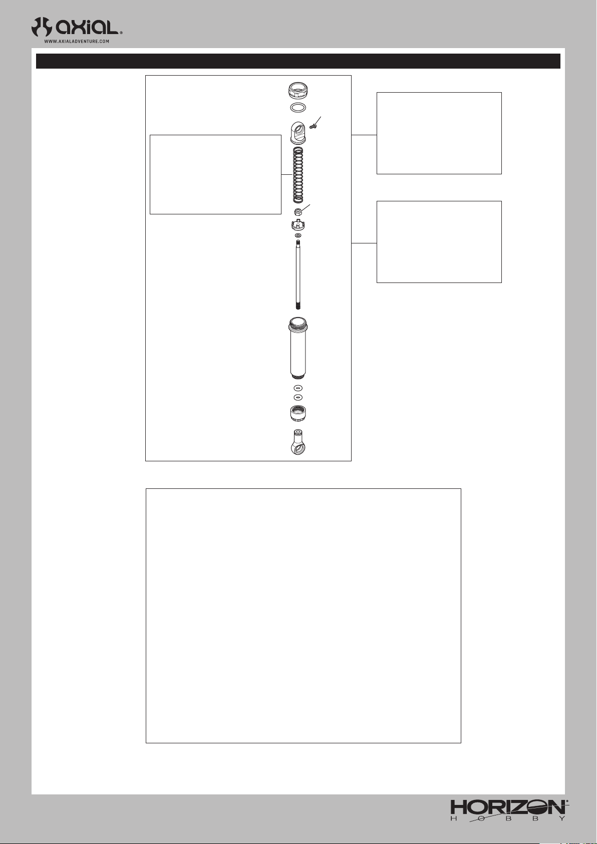
AXI-1207
AXP8 GILAMON 2.2
EXPLODED VIEWS // EXPLOSIONSZEICHNUNGEN // VUES ÉCLATÉES // VISTE ESPLOSE
SHOCK ABSORBERS
STOSSDÄMPFER
AMORTISSEURS
AMMORTIZZATORI
Front | Vorne | Avant | Anteriore:
- 7.5x50mm 0.69 lbs/in
(Red |Rot | Rouges | Rosso)
Rear | Hinten | Arrière | Posteriore:
- 7.5x56mm 0.69 lbs/in
(Red |Rot | Rouges | Rosso)
1.3mm
AXIC1146
AXIC1041
AXI-2210
Front Shock Set (2 shocks)
Vorderer Stoßdämpfersatz
(2 Stoßdämpfer)
Ensemble d’amortisseurs avant
(2amortisseurs)
Set ammortizzatori anteriori
(2 ammortizzatori)
AXI-2224
Rear Shock Set (2 shocks)
Hinterer Stoßdämpfer
(2 Stoßdämpfer)
Ensemble d’amortisseurs arrière
(2amortisseurs)
Set ammortizzatori posteriori
(2 ammortizzatori)
AXI-2225
Shock Tuning and Rebuild Kit
Includes 2 of each:
• Pistons: 1.3, 1.4, 1.5
• Springs:
- 7.5x50mm 0.69 lbs/in Red (2)
- 7.5x50mm 0.91 lbs/in Green (2)
- 7.5x56mm 0.69 lbs/in Red (2)
- 7.5x56mm 0.91 lbs/in Green (2)
- 7.5x62mm 0.69 lbs/in Red (2)
- 7.5x62mm 0.91 lbs/in Green (2)
• Replacement O-Rings
Stoßdämpfer Tuning und Umbausatz
Enthält jeweils 2 Stück:
• Kolben: 1.3, 1.4, 1.5
• Federn:
- 7,5 x 50 mm 0,69 lbs/in Rot (2)
- 7,5 x 50 mm 0,91 lbs/in Grün (2)
- 7,5 x 56mm 0,69 lbs/in Rot (2)
- 7,5 x 56 mm 0,91 lbs/in Grün (2)
- 7,5 x 62 mm 0,69 lbs/in Rot (2)
- 7,5 x 62 mm 0,91 lbs/in Grün (2)
• Ersatz-O-Ringe
Ensemble de reconstructionet
de réglage des amortisseurs
Comprend 2exemplaires de chaque:
• Pistons: 1,3 / 1,4 / 1,5
• Ressorts:
- 7,5x50mm 0,08Nm (0,69 lb-po), rouges (2)
- 7,5x50mm 0,1Nm (0,91lb-po), jaunes (2)
- 7,5x56mm 0,08Nm (0,69 lb-po), rouges (2)
- 7,5x56mm 0,1Nm (0,91 lb-po), verts (2)
- 7,5x62mm 0,08Nm (0,69 lb-po), rouges (2)
- 7,5x62mm 0,1Nm (0,91 lb-po), verts (2)
• Joints toriques de rechange
Kit tuning e ricostruzione ammortizzatori
Include 2 di ciascuno:
• Pistoni: 1,3; 1,4; 1,5
• Molle:
- 7,5x50 mm 0,69 lb/in Rosso (2)
- 7,5x50 mm 0,91 lb/in Verde (2)
- 7,5x56 mm 0,69 lb/in Rosso (2)
- 7,5x56 mm 0,91 lb/in Verde (2)
- 7,5x62 mm 0,69 lb/in Rosso (2)
- 7,5x62 mm 0,91 lb/in Verde (2)
• O-ring di ricambio
62
Page 63

PARTS LISTS // TEILELISTEN // LISTE DES PIÈCES // ELENCO COMPONENTI
Part # Description Beschreibung Description Descrizione
AXI-2156
AXI-2187
AXI-2188
AXI-2189
AXI-2190
AXI-2191
AXI-2192
AXI-2193
AXI-2196
AXI-2203
AXI-2206
AXI-2210
AXI-2211
AXI-2212
AXI-2214
AXI-2215
AXI-2216
AXI-2217
AXI-2218
AXI-2219
AXI-2220
AXI-2221
AXI-2222
AXI-2223
AXI-2224
AXI-2225
AXI-2226
AXI-2227
AXI-2228
AXI-2229
Boulder 550, 21T Brushed
Electric Motor
Body Panel Set, Clear: Gilamon
AXP8
Gear Set, Transmission, AT6:
AXP8
Cage Sides, Skid Plate, Battery
Tray: Gilamon AXP8
2.2” Mickey Thompson Baja
Boss Tires (2)
ASD Parts Set Complete: AXP8 Kompletter ASD-Teilesatz: AXP8
Interior Set, Clear: Gilamon
AXP8
ASD Shift Servo Parts: AXP8 ASD-Schaltservo-Teile: AXP8
2.2” Raceline Avenger Wheels
(2)
ASD Internal Lockout and
Spool: AXP8
Steering Axle, Assembled,
AF16P: AXP8
Shock Set Complete, Front,
IS10: AXP8
Rod Ends Set (20): AXP8 Stangenkopfsatz (20): AXP8
WB12 Driveshaft Set, Front/
Rear: AXP8
Transmission Housing Set, AT6:
AXP8
Transmission Shaft Set, AT6:
AXP8
Axle Housing, Rear, AF16P:
AXP8
Portal Box, Rear, AF16P: AXP8 Portalbox, hinten, AF16P: AXP8
Portal Box, Front, AF16P: AXP8 Portalbox, vorne, AF16P: AXP8
Axle Housing, Front, AF16P:
AXP8
Cage Parts Details: Gilamon
AXP8
Front Links, Upper/Lower, Steel:
AXP8
Rear Links, Upper/Lower, Steel:
AXP8
Steering Links, Steel, AF16P:
AXP8
Shock Set Complete, Rear, IS10:
AXP8
Shock Tuning and Rebuild Kit,
IS10: AXP8
Universal Axle Set, AF16P:
AXP8
Straight Axle Set, AF16P: AXP8
32P Portal Gears, 13/28T, AF16P:
AXP8
32P Ring/Pinion 13/43T: AXP8 32P Ring/Ritzel 13/43T: AXP8
550 21T Elektromotor 550 Moteur électrique 21T 550 Motore elettrico 21T
Karosserieteilesatz, farblos:
Gilamon AXP8
Zahnradsatz, Getriebe, AT6:
AXP8
Seitenteile Überrollkäfig,
Motorschutz, Akkufach:
Gilamon AXP8
2.2" Mickey Thompson Baja
Boss-Reifen (2)
Innensatz, farblos: Gilamon
AXP8
2.2” Raceline Avenger Reifen
(2)
ASD Interne Verriegelung und
Spule: AXP8
Lenkungsachse, montiert,
AF16P: AXP8
Stoßdämpfersatz komplett,
vorne, IS10: AXP8
WB12 Antriebswellensatz,
vorne/hinten: AXP8
Getriebegehäusesatz, AT6:
AXP8
Getriebewellensatz, AT6: AXP8
Achsgehäuse, hinten, AF16P:
AXP8
Achsgehäuse, vorne, AF16P:
AXP8
Teile Überrollkäfig Details:
Gilamon AXP8
Vordere obere/untere Stangen,
Stahl: AXP8
Hintere obere/untere Stangen,
Stahl: AXP8
Lenkstangen, Stahl, AF16P:
AXP8
Stoßdämpfersatz komplett,
hinten, IS10: AXP8
Stoßdämpfer Tuning und
Umbausatz, IS10: AXP8
Universalachsensatz, AF16P:
AXP8
Gerader Achsensatz, AF16P:
AXP8
32P Portal-Getriebe, 13/28T,
AF16P: AXP8
Ensemble de panneaux de
carrosserie, transparent:
Gilamon AXP8
Ensemble de train,
transmission, AT6: AXP8
Côtés de cage, plaque de
protection, support de batterie:
Gilamon AXP8
Pneus Mickey Thompson Baja
Boss 5,6cm (2)
Ensemble de pièces ASD
complet: AXP8
Ensemble intérieur,
transparent: Gilamon AXP8
Pièces de rechange pour servo
ASD: AXP8
Roues Raceline Avenger 5,6cm
(2)
Bobine et verrouillage interne
ASD: AXP8
Essieu de direction, assemblé,
AF16P: AXP8
Ensemble d’amortisseurs
complet, avant, IS10: AXP8
Ensemble d’embouts de bielle
(20): AXP8
Ensemble d’arbre de
transmissionWB12, avant/
arrière: AXP8
Ensemble boîte de
transmission, AT6: AXP8
Ensemble arbre de
transmission, AT6: AXP8
Carter d’essieu, arrière, AF16P:
AXP8
Boîte de portique, arrière,
AF16P: AXP8
Boîte de portique, avant,
AF16P: AXP8
Carter d’essieu, avant, AF16P:
AXP8
Détails des pièces de la cage:
Gilamon AXP8
Bras avant, supérieur/inférieur,
en acier: AXP8
Bras arrière, supérieur/
inférieur, en acier: AXP8
Tringleries de direction, en
acier, AF16P : AXP8
Ensemble d’amortisseurs
complet, arrière, IS10: AXP8
Ensemble de reconstruction et
de réglage des amortisseurs,
IS10: AXP8
Ensemble essieu universel,
AF16P: AXP8
Ensemble essieu droit, AF16P:
AXP8
Engrenages de portique 32P,
13/28T, AF16P: AXP8
Anneau/pignon 32P, 13/43T:
AXP8
Set pannelli carrozzeria,
trasparente: Gilamon AXP8
Set ingranaggi, trasmissione,
AT6: AXP8
Lati gabbia, piastra salvatelaio,
vassoio batteria: Gilamon AXP8
Ruote Boss Baja Mickey
Thompson da 2,2" (2)
Set parti ASD completo: AXP8
Set interni, trasparenti: Gilamon
AXP8
Parti servo cambio ASD: AXP8
Cerchi 2.2" Raceline Monster (2)
Spool e blocco interno ASD:
AXP8
Assale di sterzo, assemblato,
AF16P: AXP8
Set ammortizzatori completo,
anteriore, IS10: AXP8
Set teste a snodo (20): AXP8
WB12 Set albero trasmissione,
ant./post.: AXP8
Set alloggiamento trasmissione,
AT6: AXP8
Set albero trasmissione, AT6:
AXP8
Alloggiamento assale,
posteriore, AF16P: AXP8
Portal Box, posteriore, AF16P:
AXP8
Portal Box, anteriore, AF16P:
AXP8
Alloggiamento assale,
anteriore, AF16P: AXP8
Dettagli parti gabbia: Gilamon
AXP8
Tiranti anteriori, sup./inf.,
acciaio: AXP8
Tiranti posteriori, sup./inf.,
acciaio: AXP8
Tiranti sterzo, acciaio, AF16P:
AXP8
Set amm. completo, posteriore,
IS10: AXP8
Kit tuning e ricostruzione
ammortizzatori, IS10: AXP8
Set assale universale, AF16P:
AXP8
Set assale dritto, AF16P: AXP8
Ingranaggi Portal 32P, 13/28T,
AF16P: AXP8
Corona/Pignone 32P 13/43T:
AXP8
63
Page 64

Part # Description Beschreibung Description Descrizione
AXI-2230
AXI-2231
AXI-2232
AXI235109
AXI235110
AXI235167
AXI236103
AXI237009
AXIC0005
AXIC0012
AXIC0014
AXIC0114
AXIC0115
AXIC0116
AXIC0146
AXIC0186
AXIC0218
AXIC0221
AXIC0230
AXIC0291
AXIC0393
AXIC1041
AXIC1045
AXIC1053
AXIC1072
AXIC1120
AXIC1146
AXIC1195
AXIC1391
AXIC1495
AXIC3066
LOS235015
LOS247001
LOSA6940
LOSA6944
SPMR2340T
SPMS682
SPMSR515
12mm Hex Hub Set (4): AXP8
WB12 Driveshaft Coupler Set:
AXP8
Multi-Color LED Rock Lights w/
Controller
M3 x 14mm Button Head Screw
(10)
M3 x 16mm Button Head Screw (10)
M2.5 x 8mm Flat Head Screw (10)
2.5mm x 4.6mm x 0.5mm Washer (10) 2,5x4,6x0,5mm Unterlegscheibe (10)
5x13x4mm Ball Bearing (2) 5x13x4mm Kugellager (2) Roulement 5x13x4mm (2) Cuscinetti 5x13x4mm (2)
Hex Socket Button Head Black
M3x6mm (10)
Hex Socket Button Head
M3x25mm Black (10)
AXA121 Hex Socket Button
Head M3x30mm Black (10)
Hex Socket Button Head 3x8mm
(10)
Hex Socket Button Head
M3x10mm Black (10)
Hex Socket Button Head
M3x12mm Black (10)
Hex Socket Flat Head M3x12mm
Black (10)
AXA186 Set Screw M3x16mm
Black Oxide (10)
Bearing 5x10x4mm (2)
Bearing 5x11x4mm (2)
Bearing 10x15x4mm
AXA291 Set Screw M4x4mm
Black Oxide (6)
AXA1393 E-Clip E2.5 (10) E-Clip, 2,5mm E-Clip, 2,5mm E-Clip, 2,5mm
AXA1041 Nylon Locknut 2.5 (10) 2.5 Sicherungsmuttern (10) Contre-écrous 2.5 (10) Dadi 2.5 (10)
AXA1045 Nylon Locknut M4
Black (10)
AXA1053 Nylon Locking Hex
Nut M3 Black (10)
AXA1072 Washer 3x8x0.5mm (10) 3x8x0.5mm Unterlegscheibe (10) Rondelle, 3x8x0.5mm (10) Rondelle 3x8x0.5mm (10)
Hex Socket Flat Head 3x10mm
(10)
AX31146 Hex Sckt Button Hd
Screw M2x4mm Black (10)
AX31195 Hex Socket Button
Head 2.6x12mm (10)
AXA1391 E4 E-Clip (10) E-Clip, 4mm E-Clip, 4mm E-Clip, 4mm
AX31495 Bearing 8x12x3.55mm (2) 8x12x3.55mm Kugellager (2) Roulement 8x12x3.55mm (2) Cuscinetti 8x12x3.55mm (2)
Cap Head M2x8mm Black (10)
Lock Nut, Flanged M5 x 0.8
Serrated (10)
6x15x5mm Metal Shield Ball
Bearing (4)
6x12x4mm Sealed Ball Bearing
(4)
15 x 21 x 4 Shielded Ball
Bearing(2)
DX3 SMART Tx with Thumb Steer DX3 SMART 3CH Sender DX3 Smart 3CH Émetteur DX3 Smart 3CH Trasmettitore
S682 - 20kg servo , steel gear
25T
SR515 DSMR 5 CH Receiver
12mm Sechskantnabensatz (4):
AXP8
WB12
Antriebswellenkupplungssatz: AXP8
Mehrfarbige LEDGeländescheinwerfer mit
Steuergerät
Rundkopfschraube, M3x14mm
(10)
Rundkopfschraube, M3x16mm (10) Vis à tête bombée, M3x16mm (10) Vite a testa tonda M3x16mm (10)
Flachkopfschraube, M2,5x8mm
(10)
Sechskant-Rundkopfschraube
M3x6mm
Sechskant-Rundkopfschraube
M3x25mm
Sechskant-Rundkopfschraube
M3x30mm
Sechskant-Rundkopfschraube
M3x8mm
Sechskant-Rundkopfschraube
M3x10mm
Sechskant-Rundkopfschraube
M3x12mm
Sechskant-Flachkopfschraube,
M3x12mm
Stellschraube, M3x16mm,
Schwarzoxid (10)
Lager 5x10x4mm Roulement 5x10x4mm Cuscinetto 5x10x4mm
Lager 5x11x4mm Roulement 5x11x4mm Cuscinetto 5x11x4mm
Lager 10x15x4mm Roulement 10x15x4mm Cuscinetto 10x15x4mm
Stellschraube, M4x4mm,
Schwarzoxid (6)
M4 Sicherungsmuttern (10) Contre-écrous M4 (10) Dadi M4 (10)
M3 Sicherungsmuttern (10) Contre-écrous M3 (10) Dadi M3 (10)
Sechskant-Flachkopfschraube,
M3x10mm
Sechskant-Rundkopfschraube
M2x4mm (10)
Sechskant-Rundkopfschraube
2.6x12mm (10)
Inbusschraube M2x8mm,
schwarz (10)
Nylon-Feststellflanschmutter,
M5 x 0.8 (10)
6x15x5mm Kugellager (4) Roulement 6x15x5mm (4) Cuscinetti 6x15x5mm (4)
6x12x4mm abgedichtetes
Kugellager (4)
15x21x4mm abgedichtetes
Kugellager (24)
S682 - 20kg
Metallgetriebeservo, 25T
SR515 DSMR 5-KanalEmpfänger
Ensemble moyeu hexagonal
12mm (4): AXP8
Ensemble coupleur d’arbre de
transmission WB12: AXP8
Système d’éclairage
multicolore à DEL RockLights
avec contrôleur
Vis à tête bombée, M3x14mm
(10)
Vis à tête plate, M2,5x8mm (10)
Rondelle, 2,5x4,6x0,5mm (10) Rondelle 2,5x4,6x0,5mm (10)
Douille à six pans à tête
bombée M3x6mm
Douille à six pans à tête
bombée M3x25mm
Douille à six pans à tête
bombée M3x30mm
Douille à six pans à tête
bombée M3x8mm
Douille à six pans à tête
bombée M3x10mm
Douille à six pans à tête
bombée M3x12mm
Douille à six pans à tête plate
M3x12mm
Vis de fixation M3x16mm brunie
(10)
Vis de fixation M4x4mm brunie
(6)
Douille à six pans à tête plate
M3x10mm
Douille à six pans à tête
bombée M2x4mm (10)
Douille à six pans à tête
bombée 2.6x12mm (10)
Vis d’assemblage creuse
M2x8mm noire (10)
Contre-écrou en nylon strié M5
x 0.8 (10)
Roulement à billes hermétique
6x12x4mm (4)
Roulement à billes hermétique
15x21x4mm (2)
Servo à engrenages
métalliques S682 - 20kg 25T
Récepteur 5 canaux SR515
DSMR
Set mozzi esagonali 12 mm (4):
AXP8
WB12 Set acc. albero
trasmissione: AXP8
Luci LED Rock multicolore con
controller
Vite a testa tonda M3x14mm
(10)
Vite a testa piana M2,5x8mm
(10)
Vite a testa tonda con esagono
incassato M3x6mm
Vite a testa tonda con esagono
incassato M3x25mm
Vite a testa tonda con esagono
incassato M3x30mm
Vite a testa tonda con esagono
incassato M3x8mm
Vite a testa tonda con esagono
incassato M3x10mm
Vite a testa tonda con esagono
incassato M3x12mm
Vite a testa piana con esagono
incassato M3x12mm
Vite di fermo M3x16mm ossido
nero (10)
Vite di fermo M4x4 mm ossido
nero (6)
Vite a testa piana con esagono
incassato M3x10mm
Vite a testa tonda con esagono
incassato M2x4mm (10)
Vite a testa tonda con esagono
incassato 2.6x12mm (10)
Vite a testa cilindrica M2x8mm
nero (10)
Dato flangiato Nylock nero M5 x
0.8 (10)
Cuscinetti a sfera sigillato
6x12x4mm (4)
Cuscinetti a sfera sigillato
15x21x4mm (2)
S682 - 20kg Servo, ingranaggio
metallico 25T
SR515 DSMR Ricevitore a 5
canali
64
Page 65

Part # Description Beschreibung Description Descrizione
SPMSSX117AX
SPMXSE1070
TLR245016
TLR5900
TLR5907
TLR6289 Set Screw, M3 x 5mm (10)
SX117AX Micro Servo Metal
Gear/Case, 250mm Lead
FIRMA 70A Brushed Smart WP ESC
M3 Flanged Lock Nuts (10)
Button Head Screws, M3 x 5mm (10)
Button Head Screws, M3 x
40mm (4)
SX117AX Mikro
Metallgetriebeservo
70 Amp Geschwindigkeitsregler ESC 70 Amp Firma Firma ESC 70 Amp
M3 Sicherungsmuttern mit
Flansch (10)
Rundkopfschraube, M3x5mm (10) Vis à tête bombée, M3x5mm (10)
Rundkopfschraube, M3x40mm
(4)
Stellschraube, M3 x 5mm (10) Vis de fixation M3 x 5mm (10) Vite di fermo M3 x 5mm
Servo à engrenages
métalliques Micro SX117AX
Contre-écrous à collet M3 (10) Dadi flangiati M3 (10)
Vis à tête bombée, M3x40mm
(4)
SX117AX Micro Servo,
ingranaggio metallico
Vite a testa tonda M3x5mm (10)
Vite a testa tonda M3x40mm (4)
OPTIONAL PARTS / OPTIONALE TEILE / PIÈCES EN OPTION / PARTI OPZIONALI
Part # Description Beschreibung Description Descrizione
AXI-2191
AXI-2194
AXI-2195
AXI-2199
AXI-2200
AXI-2201
AXI-2202
AXI-2204
AXI-2205
AXI-2206
AXI-2207
AXI-2208
AXI-2209
AXI-2225
AXI-2858
AXI232046
AXIC0834
AXIC0836
AXIC2015
AXIC8137
ASD Parts Set Complete: AXP8
Body Panel Set, Aluminum:
Gilamon AXP8
Transmission Motor Plate,
Aluminum, AT6: AXP8
32P Overdrive Ring/Pinion
13T/38T (6.30:1): AXP8
Portal Knuckles (L/R), Brass
(69.5g ea), AF16P: AXP8
Portal Cvr & Wghts,
Brass(122.4g,34.6g ea), AF16P:
AXP8
Steering Links Set, Titaniumm,
AF16P: AXP8
Front Upper/Lower Links Set,
Titanium: AXP8
Rear Upper/Lower Links Set,
Titanium: AXP8
Steering Axle, Assembled,
AF16P: AXP8
Rear Upper/Lower 4WS Links
Set, Titanium: AXP8
32P Portal Gears Underdrive
12/29T (11.5%), AF16P: AXP8
32P Portal Gears Overdrive
14/27T (11%), AF16P: AXP8
Shock Tuning and Rebuild Kit,
IS10: AXP8
Front Upper Link Mount,
Aluminum, AF16P: AXP8
Aluminum Hex Hub, 12mm,
Hard Anodized: RBX10
Aluminum Servo Horn 23T Aluminium-Servohorn, 23T
Aluminum Servo Horn 25T Aluminium-Servohorn, 25T
2.2 Ripsaw Tires X Compound
(2)
2.2 Rebel Wheels 41mm Wide
Chrm/Blk (2)
Kompletter ASD-Teilesatz:
AXP8
Karosserieteilesatz,
Aluminium: Gilamon AXP8
Getriebe-Motorplatte,
Aluminium, AT6: AXP8
32P Overdrive Ring/Ritzel
13T/38T (6,30:1): AXP8
Portal-Achsschenkel (L/R),
Messing (69,5 g pro Stück),
AF16P: AXP8
Portal Cvr & Wghts, Messing
(122,4g, 34,6g pro Stück),
AF16P: AXP8
Lenkgliedsatz, Titan, AF16P:
AXP8
Satz obere/untere
Verbindungsglieder vorne,
Titan: AXP8
Satz obere/untere
Verbindungsglieder hinten,
Titan: AXP8
Lenkungsachse, montiert,
AF16P: AXP8
Hintere obere/untere 4WSVerbindungsglieder, Titan:
AXP8
32P PortalUntersteuerungsgetriebe
12/29T (11,5%), AF16P: AXP8
32P PortalÜbersteuerungsgetriebe
14/27T (11%), AF16P: AXP8
Stoßdämpfer Tuning und
Umbausatz, IS10: AXP8
Oberlenkerhalterung vorne,
Aluminium, AF16P: AXP8
Aluminium-Sechskantnabe,
12mm, harteloxiert: RBX10
2.2 Ripsaw-Räder X Compound
(2)
2.2 Rebel-Räder 41mm breit
chrom/schwarz (2)
Ensemble de pièces ASD
complet: AXP8
Ensemble de panneaux de
carrosserie, en aluminium:
Gilamon AXP8
Plaque moteur de
transmission, en aluminium,
AT6: AXP8
Anneau/pignon de
surmultiplication 32P 13T/38T
(6.30:1): AXP8
Rotules de portique (G/D), en
laiton (69,5g chacun), AF16P:
AXP8
Cache et contrepoids de
portique, en laiton (122,4g,
34,6g chacun), AF16P: AXP8
Ensemble tringleries de
direction, en titane, AF16P:
AXP8
Ensemble tringleries de
direction avant supérieur/
inférieur, en titane: AXP8
Ensemble tringleries de
direction arrière supérieur/
inférieur, en titane: AXP8
Essieu de direction, assemblé,
AF16P: AXP8
Ensemble tringleries de
direction 4WS arrière
supérieur/inférieur, en titane:
AXP8
Engrenages de portique de
sous-multiplication 32P 12/29T
(11,5%), AF16P: AXP8
Engrenages de portique de
surmultiplication 32P 14/27T
(11%), AF16P: AXP8
Ensemble de reconstruction et
de réglage des amortisseurs,
IS10: AXP8
Support de bras supérieur
avant, en aluminium, AF16P:
AXP8
Moyeu hexagonal en
aluminium, 12mm, à
anodisation dure: RBX10
Renvoi de commande du servo
en aluminium 23T
Renvoi de commande du servo
en aluminium 25T
Pneus Ripsaw 2.2 X Compound
(2)
Roues Rebel 2.2 41mm de
large chrome/noires (2)
Set parti ASD completo: AXP8
Set pannelli carrozzeria,
alluminio: Gilamon AXP8
Piastra motore di trasmissione,
alluminio, AT6: AXP8
Corona/Pignone Overdrive 32P
13T/38T (6.30:1): AXP8
Fusi a snodo Portal (Sx/Dx),
ottone (69,5 g cad.), AF16P:
AXP8
Coperchi e pesi Portal, ottone
(122,4 g, 34,6 g cad.), AF16P:
AXP8
Set tiranti sterzo, Titanio,
AF16P: AXP8
Set tiranti anteriori sup./inf.,
titanio: AXP8
Set tiranti posteriori sup./inf.,
titanio: AXP8
Assale di sterzo, assemblato,
AF16P: AXP8
Set tiranti posteriore sup./inf.
4WS, titanio: AXP8
Ingranaggi Portal Underdrive
32P 12/29T (11,5%), AF16P:
AXP8
Ingranaggi Portal Overdrive
32P 14/27T (11%), AF16P: AXP8
Kit tuning e ricostruzione
ammortizzatori, IS10: AXP8
Supporto tiranti anteriori
superiori, Alluminio, AF16P:
AXP8
Mozzo esagonale in alluminio,
12 mm, anodizzato: RBX10
Squadretta servo alluminio,
23T
Squadretta servo alluminio,
25T
Ruote 2.2 Ripsaw X Compound
(2)
Cerchi 2.2 Rebel 41 mm larghi
Cromo/Nero (2)
65
Page 66
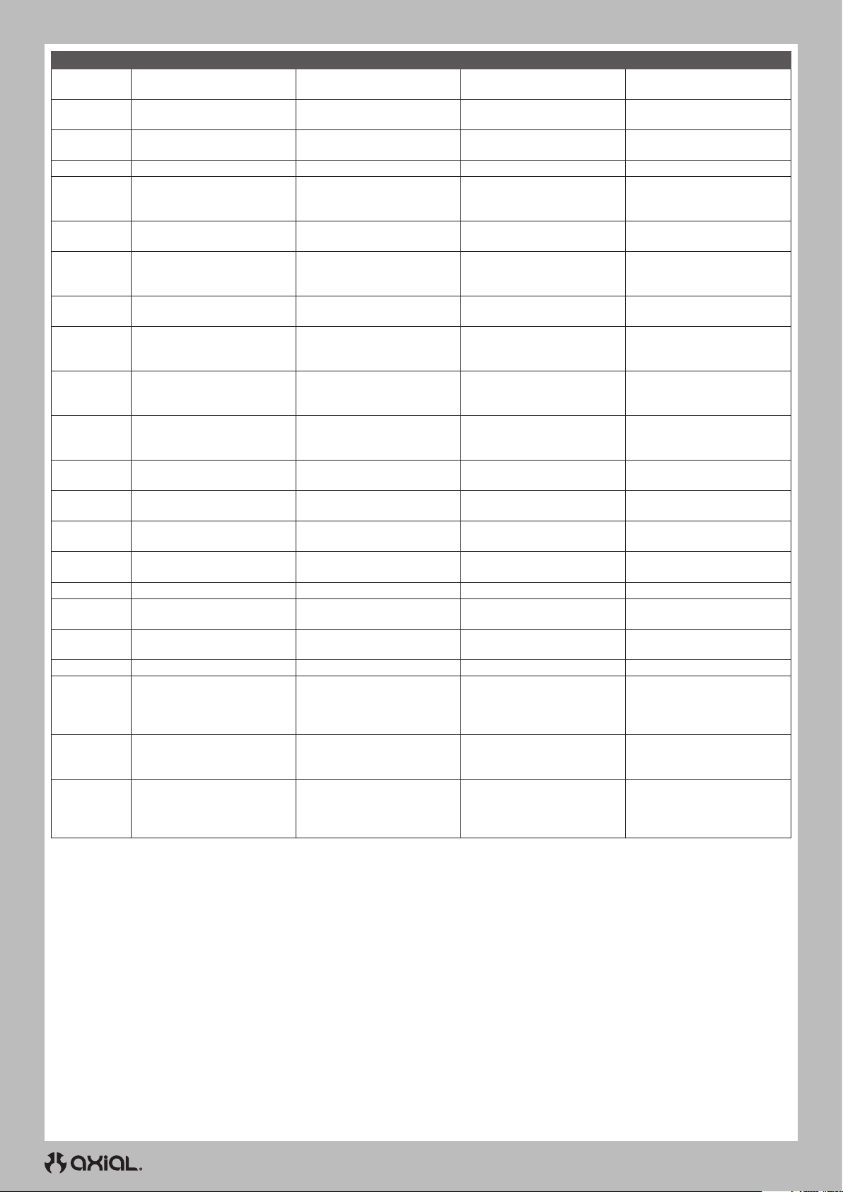
Part # Description Beschreibung Description Descrizione
DYNT0500
PRO1010714
PRO1013203
PRO1013214
PRO1017814
PRO1019103
PRO1020314
PRO1022014
PRO116614
PRO280503
PRO617600
SPMSS6230
SPMSS6240
SPMSS6250
SPMSS6285
SPMSS7110
SPMSSX117
SPMSSX117AX
SPMX-1016
SPMXSEM1040B
SPMXSEMC08
SPMXSEMC09
Startup Tool Set: ECX/VTR/HPI
Interco TSL SX S Swamper XL
2.2 G8 Truck Tire
Hyrax 2.2 Predator Truck Tires
(2) for F/R
Hyrax 2.2 G8 Truck Tire (2) Hyrax 2.2 G8 Truck-Reifen (2) Pneus camion Hyrax 2.2 G8 (2) Ruote Hyrax 2.2 G8 (2)
1/10 Ibex Ultra Cmp G8 F/R 2.2
CrwlrTire NoFm (2)
Trencher 2.2 Predator Tires
for F/R
1/10 MickeyThompson
BajaProX G8 F/R 2.2 Crawlr (2)
1/10 Hyrax LP G8 Front/Rear 2.2
Crawler Tires (2)
Fr R Interco TSL Super
Swamper 2.2 G8 Crawl Tire
1/10 Impluse F/R 2.2 12mm
Crawler Whls (2) Black
2.2 Dual Stage Closed Cell
Crawl Foam Insert (2)
S6230 Ultra Torq Mid Speed
Digital WP Metal Servo
S6240 High Torq High Speed
Digital WP Metal Servo
S6250 Ultra Torque High Speed
Digi WP Metal Servo
1/8 HighTorque Race Servo 1/8 HighTorque Race Servo
Spektrum 1/10 Servo Winch Spektrum 1/10 Servo Winde Bobine de servo 1/10 Spektrum Argano servo Spektrum 1/10
SX117 Micro Servo Metal
Gear/Case
SX117AX Micro Servo Metal
Gear/Case, 250mm Lead
UBEC 10A (2-6S) UBEC 10A (2-6S) UBEC 10A (2-6S) UBEC 10A (2-6S)
Firma 2 in 1 Brushless Crawler
Motor ESC: 2300Kv
Firma Sensored 1/10th Crawler
Power System w/Smart
Firma 60A BL Smart ESC
2800Kv Sense Mot Crawl Com
Startup-Werkzeugsatz: ECX/
VTR/HPI
Interco TSL SX S Swamper XL
2.2 G8 Truck-Reifen
Hyrax 2.2 Predator Truck-
Reifen (2) für Vo/Hi
1/10 Ibex Ultra Cmp G8 Vo/Hi
2.2 CrwlrTire NoFm (2)
Trencher 2.2 Predator Reifen
für Vo/Hi
1/10 MickeyThompson
BajaProX G8 Vo/Hi 2.2 Crawlr
(2)
1/10 Hyrax LP G8 vorne/hinten
2.2 Crawler-Reifen (2)
Fr R Interco TSL Super
Swamper 2.2 G8 Crawl-Reifen
1/10 Impluse Vo/Hi 2.2 12mm
Crawler-Reifen (2) Schwarz
2.2 Dual Stage Closed Cell
Crawl-Schaumstoffeinsatz (2)
S6230 U-T/M-S Digitaler WP
Servo
S6240 U-T/M-S Digitaler WP
Servo
S6250 U-T / H-S Digitaler HV
WP Servo
SX117 Mikro
Metallgetriebeservo
SX117AX Mikro
Metallgetriebeservo
Firma 2-in-1 Bürstenloser
Crawler-Motor
Geschwindigkeitsregler:
2300Kv
Firma Sensored 1/10 Crawler
Power System Smart
Firma 60A BL Smart ESC
2800Kv Sense Mot Crawl Com
Ensemble d’outils de
démarrage: ECX/VTR/HPI
Pneu camion Interco TSL SX S
Swamper XL 2.2 G8
Pneus camion Hyrax 2.2
Predator (2) avant/arrière
Pneus Crawler sans mousse
2.2 avant/arrière G8 1/10 Ibex
Ultra Cmp (2)
Pneus Trencher 2.2 Predator
avant/arrière
Crawler 2.2 MickeyThompson
BajaProX G8 1/10 avant/arrière
(2)
Pneus Crawler 2.2 Hyrax LP G8
1/10 avant/arrière (2)
Pneu Crawler Interco TSL
Super Swamper 2.2 G8 avant/
arrière
Roues Crawler 12mm 2.2
Impluse 1/10 avant/arrière,
noires (2)
Fond en mousse Crawler à
cellules fermées Dual Stage
2.2 (2)
Servo étanche numérique U-T /
M-S S6230
Servo étanche numérique U-T /
M-S S6240
Servo numérique étanche
haute tension U-T / H-S S6250
Servo de course à couple
élevé 1/8
Servo à engrenages
métalliques Micro SX117
Servo à engrenages
métalliques Micro SX117AX
Variateur ESC/moteur sans
balais 2-en-1 Crawler Firma:
2300kV
Système d’alimentation
Crawler 1/10 Firma avec
capteurs et Smart
Ensemble Crawler moteur avec
capteurs sans balais 2800kV/
variateur ESC Smart sans
balais 60A Firma
Set attrezzi base: ECX/VTR/HPI
Ruota Interco TSL SX S
Swamper XL 2.2 G8 Truck
Ruote Hyrax 2.2 Predator Truck
(2) per ant./post.
Ruote 1/10 Ibex Ultra Cmp G8
F/R 2.2 Crawler NoFm (2)
Ruote Trencher 2.2 Predator
per ant./post.
Ruote 1/10 MickeyThompson
BajaProX G8 ant./post. 2.2
Crawler (2)
Ruote 1/10 Hyrax LP G8 Ant./
Post. 2.2 Crawler (2)
Ruota Interco TSL Super
Swamper 2.2 G8 Crawler ant./
post.
Ruote 1/10 Impulse 2.2 12 mm
Crawler ant./post. (2) Nero
Inserto schiuma 2.2 cella
chiusa doppio stadio (2)
Servo digitale S6230 U-T/M-S
imp
Servo digitale S6240 U-T/M-S
imp
Servo digitale S6250 U-T/H-S
imp HV
Servo gara alta coppia 1/8
SX117 Micro Servo,
ingranaggio metallico
SX117AX Micro Servo,
ingranaggio metallico
Motore ESC 2 in 1 Firma
Brushless Crawler: 2300 Kv
Sistema di potenza Firma con
sensori 1/10 Crawler con Smart
Combo ESC motore Firma 60 A
BL Smart 2800 Kv con sensori
Crawler
66
Page 67
RECOMMENDED // EMPFOHLEN // RECOMMANDÉ // CONSIGLIATO
Part # Description Beschreibung Description Descrizione
SPMX-1047
SPMX22003S50
SPMX223S100
SPMX223S30
SPMX223S50
SPMX32003S30
SPMX40003S30
SPMX43S30
SPMX53S100H3
SPMX53S30H3
SPMX53S50H3
SPMXC2000
SPMXC2010
SPMXC2050
SPMX-1033
SPM6125
SPM6420
SPMR5025
SPMR6215G
SPMR6215O
Smart G2 Trail Pro 3400mAh 3S
11.1V 50C LiPo w/ IC3
2200mAh 3S 11.1V 50C Smart
LiPo Battery; IC3
2200mAh 3S 11.1V Smart G2
LiPo 100C; IC3
2200mAh 3S 11.1V Smart G2
LiPo 30C; IC3
2200mAh 3S 11.1V Smart G2
LiPo 50C; IC3
3200mAh 3S 11.1V Smart LiPo
30C; IC3
4000mAh 3S 11.1V Smart LiPo
Battery 30C; IC3
4000mAh 3S 11.1V Smart G2
LiPo Battery 30C; IC3
5000mAh 3S 11.1V Smart G2
Hard Case LiPo 100C IC3
5000mAh 3S 11.1V Smart G2
LiPo 30C Hard Case; IC3
5000mAh 3S 11.1V Smart G2
LiPo 50C Hard Case; IC3
Smart S2100 G2 AC Charger,
2x100W
Smart S2200 G2 AC Charger,
2x200W
S155 55W AC G2 Smart
Charger
Smart Powerstage Surface
Bundle: 5000mAh 3S 50C LiPo
Battery (IC3) / 100W S100
Charger
DX6C TX w/SR315 RX
iXSR Surface Transmitter with
SR515 Receiver
DX5 Pro 2021 DSMR TX Only DX5 Pro 2021 DSMR nur TX
DX6 Rugged 6 Channel DSMR
Transmitter Only, Green
DX6 Rugged 6 Channel DSMR
Transmitter Only, Orange
G2 3400mAh 3S 11,1V Smart
50C; IC3
2200mAh 3S 11,1V Smart 50C;
IC3
2200mAh 3S 11,1V Smart G2
100C; IC3
2200mAh 3S 11,1V Smart G2
30C; IC3
2200mAh 3S 11,1V Smart G2
50C; IC3
3200mAh 3S 11,1V Smart 30C;
IC3
4000mAh 3S 11,1V Smart 30C;
IC3
4000mAh 3S 11,1V Smart G2
30C; IC3
5000mAh 3S 11,1V Smart G2
100C; IC3
5000mAh 3S 11,1V Smart G2
30C; IC3
5000mAh 3S 11,1V Smart G2
50C; IC3
Smart S2100 G2 WechselstromLadegerät, 2x100W
Smart S2200 G2 WechselstromLadegerät, 2x2100W
Smart S155 G2 WechselstromLadegerät 55W
Smart OberflächenLeistungsteilpaket: 5000mAh
3S 50C LiPo Akku (IC3) / 100W
S100 Ladegerät
DX6 Rugged DSMR TX mit
SR315 RX
iXSR-Oberflächensender mit
SR515-Empfänger
Nur DX6 Rugged DSMR TX,
Grün
Nur DX6 Rugged DSMR TX,
Orange
G2 3400mAh 3S 11,1V Smart
50C; IC3
2200mAh 3S 11,1V Smart 50C;
IC3
2200mAh 3S 11,1V Smart G2
100C; IC3
2200mAh 3S 11,1V Smart G2
30C; IC3
2200mAh 3S 11,1V Smart G2
50C; IC3
3200mAh 3S 11,1V Smart 30C;
IC3
4000mAh 3S 11,1V Smart 30C;
IC3
4000mAh 3S 11,1V Smart G2
30C; IC3
5000mAh 3S 11,1V Smart G2
100C; IC3
5000mAh 3S 11,1V Smart G2
30C; IC3
5000mAh 3S 11,1V Smart G2
50C; IC3
Chargeur c.a. Smart G2 S2100,
2x100W
Chargeur c.a. Smart G2 S2200,
2x200W
Chargeur c.a. Smart G2 S155,
55W
Ensemble de surface Smart
Powerstage: Batterie LiPo 5000mAh 3S 50C (IC3) /
chargeur 100W S100
Émetteur DX6 robuste DSMR
avec récepteur SR315
Émetteur de surface iXSR avec
récepteur SR515
DX5 Pro 2021 DSMR TX
uniquement
Émetteur uniquement DX6
robuste DSMR, vert
Émetteur uniquement DX6
robuste DSMR, orange
G2 3400mAh 3S 11,1V Smart
50C; IC3
2200mAh 3S 11,1V Smart 50C;
IC3
2200mAh 3S 11,1V Smart G2
100C; IC3
2200mAh 3S 11,1V Smart G2
30C; IC3
2200mAh 3S 11,1V Smart G2
50C; IC3
3200mAh 3S 11,1V Smart 30C;
IC3
4000mAh 3S 11,1V Smart 30C;
IC3
4000mAh 3S 11,1V Smart G2
30C; IC3
5000mAh 3S 11,1V Smart G2
100C; IC3
5000mAh 3S 11,1V Smart G2
30C; IC3
5000mAh 3S 11,1V Smart G2
50C; IC3
Caricbatt Smart G2 S2100 CA,
2x100 W
Caricbatt Smart G2 S2200 CA,
2x200 W
Caricbatt Smart G2 S155 CA,
55 W
Smart Powerstage Bundle
superficie: Batteria 5000
mAh 3S 50C LiPo (IC3) /
Caricabatterie 100 W S100
Tx DX6 Rgd DSMR con RX
SR315
Trasmittente di superficie iXSR
con Ricevitore SR515
Solo DX5 Pro 2021 DSMR TX
DX6 Rugged DSMR solo Tx,
verde
DX65 Rugged DSMR solo Tx,
aranc
67
Page 68

facebook.com/axialinc | instagram.com/axialracing | twitter.com/axialrc
youtube.com/axialvideos | flickr.com/axialrc
©2024 Horizon Hobby, LLC.
Axial, the Axial logo, DSM, IC3 and the Horizon Hobby logo are trademarks or registered trademarks of Horizon Hobby, LLC.
The Spektrum trademark is used with permission of Bachmann Industries, Inc. Nitto® and Trail Grappler® are registered trademarks of Nitto Tire U.S.A., Inc.
The CRC name and logo are trademarks or registered trademarks of Casey Currie Motorsports. The Raceline Wheels name and logo are trademarks or registered
trademarks of Allied Wheel Components, Inc. All other trademarks, service marks and logos are property of their respective owners.
Completed 1/25 AXI-1207 478400.1
 Loading...