

Page 1

AXI03029
INSTRUCTION MANUAL
BEDIENUNGSANLEITUNG
MANUEL D’UTILISATION
MANUALE DI ISTRUZIONI
Scan the QR code and select the Manuals and Support quick links from the
product page for the most up-to-date manual information.
Scannen Sie den QR-Code und wählen Sie auf der Produktseite die Quicklinks
Handbücher und Unterstützung, um die aktuellsten Informationen zu Handbücher.
Scannez le code QR et sélectionnez les liens rapides Manuals and Support sur la
page du produit pour obtenir les informations les plus récentes sur le manuel.
Scannerizzare il codice QR e selezionare i Link veloci Manuali e Supporto dalla
pagina del prodotto per le informazioni manuali più aggiornate.
Page 2
EN
NOTICE
All instructions, warranties and other collateral documents are subject to change at the sole discretion of Horizon Hobby, LLC. For up-to-date
product literature, visit horizonhobby.com or towerhobbies.com and click on the support or resources tab for this product.
MEANING OF SPECIAL LANGUAGE
The following terms are used throughout the product literature to indicate various levels of potential harm when operating this product:
WARNING: Procedures, which if not properly followed, create the probability of property damage, collateral damage, and serious injury OR
create a high probability of superficial injury.
CAUTION: Procedures, which if not properly followed, create the probability of physical property damage AND a possibility of serious injury.
NOTICE: Procedures, which if not properly followed, create a possibility of physical property damage AND a little or no possibility of injury.
WARNING: Read the ENTIRE instruction manual to become familiar with the features of the product before operating. Failure to operate
the product correctly can result in damage to the product, personal property and cause serious injury.
This is a sophisticated hobby product. It must be operated with caution and common sense and requires some basic mechanical ability. Failure to
operate this Product in a safe and responsible manner could result in injury or damage to the product or other property. This product is not intended for
use by children without direct adult supervision. Do not use with incompatible components or alter this product in any way outside of the instructions
provided by Horizon Hobby, LLC. This manual contains instructions for safety, operation and maintenance. It is essential to read and follow all the
instructions and warnings in the manual, prior to assembly, setup or use, in order to operate correctly and avoid damage or serious injury.
Age Recommendation: Not for children under 14 years. This is not a toy.
SAFETY PRECAUTIONS AND WARNINGS
As the user of this product, you are solely responsible for operating in a manner that does not endanger yourself and others or result in damage
to the product or property of others.
This model is controlled by a radio signal subject to interference from many sources outside your control. This interference can cause momentary
loss of control, so it is advisable to always keep a safe distance in all directions around your model as this margin will help avoid collisions or injury.
• Never operate your model with low transmitter batteries.
• Always operate your model in open spaces away from full-size
vehicles, traffic and people.
• Never operate the model in the street or in populated areas for any
reason.
• Carefully follow the directions and warnings for this and any optional
support equipment (chargers, rechargeable battery packs, etc.) you use.
• Keep all chemicals, small parts and anything electrical out of the
reach of children.
• Never lick or place any portion of the model in your mouth as it could
cause serious injury or even death.
• Exercise caution when using tools and sharp instruments.
• Take care during maintenance as some parts may have sharp edges.
• Immediately after using your model, do NOT touch equipment
such as the motor, electronic speed control and battery, because
they generate high temperatures. You may burn yourself seriously
touching them.
• Do not put fingers or any objects inside rotating and moving parts, as
this may cause damage or serious injury.
• Always turn on your transmitter before you turn on the receiver in the
car. Always turn off the receiver before turning your transmitter off.
• Keep the wheels of the model off the ground when checking the
operation of the radio equipment.
WARNING AGAINST COUNTERFEIT PRODUCTS: Always purchase from a Horizon Hobby, LLC authorized dealer to ensure
authentic high-quality Spektrum product. Horizon Hobby, LLC disclaims all support and warranty with regards, but not limited to,
compatibility and performance of counterfeit products or products claiming compatibility with DSM® or Spektrum technology.
2
Page 3

TABLE OF CONTENTS
Water-Resistant Vehicle With Waterproof Electronics .............................3
Box Contents.....................................................................................................4
Required Equipment ........................................................................................ 4
Recommended Tools ....................................................................................... 4
Getting Started Checklist ................................................................................5
Vehicle Parts ..................................................................................................... 5
Charge the Vehicle Battery ............................................................................ 6
Install the Transmitter Batteries .................................................................... 6
Transmitter Functions ......................................................................................6
SPMSR315 Dual Protocol Receiver .............................................................. 7
Adjusting the Vehicle Battery Tray................................................................7
Install the Vehicle Battery .............................................................................. 8
Binding ...............................................................................................................8
Range-Checking the Radio System .............................................................. 9
Vehicle Maintenance ...................................................................................... 9
Firma 40A Brushed ESC ................................................................................ 10
Gear Ratios......................................................................................................10
Troubleshooting ..............................................................................................11
Limited Warranty ............................................................................................12
Warranty and Service Contact Information .............................................. 12
FCC Information ..............................................................................................13
IC Information ................................................................................................. 13
Compliance Information for the European Union ..................................... 13
Exploded Views .............................................................................................. 50
Parts Lists ........................................................................................................55
Recommended Parts ..................................................................................... 57
Optional Parts ................................................................................................. 57
Electronics ...................................................................................................... 57
Notes ................................................................................................................58
WATER-RESISTANT VEHICLE WITH WATERPROOF ELECTRONICS
EN
Your new Horizon Hobby vehicle has been designed and built with
a combination of waterproof and water-resistant components to
allow you to operate the product in many “wet conditions,” including
puddles, creeks, wet grass, snow and even rain.
While the entire vehicle is highly water-resistant, it is not completely
waterproof and your vehicle should NOT be treated like a submarine.
The various electronic components used in the vehicle, such as the
Electronic Speed Control (ESC), servo(s) and receiver are waterproof,
however, most of the mechanical components are water-resistant and
should not be submerged.
Metal parts, including the bearings, hinge pins, screws and nuts, as
well as the contacts in the electrical cables, will be susceptible to
corrosion if additional maintenance is not performed after running in
wet conditions. To maximize the long-term performance of your vehicle
and to keep the warranty intact, the procedures described in the “Wet
Conditions Maintenance” section below must be performed regularly
if you choose to run in wet conditions. If you are not willing to perform
the additional care and maintenance required, then you should not
operate the vehicle in those conditions.
CAUTION: Failure to exercise caution while using this
product and complying with the following precautions could
result in product malfunction and/or void the warranty.
GENERAL PRECAUTIONS
• Read through the wet conditions maintenance procedures and make
sure that you have all the tools you will need to properly maintain your
vehicle.
• Not all batteries can be used in wet conditions. Consult the battery
manufacturer before use. Caution should be taken when using Li-Po
batteries in wet conditions.
• Most transmitters are not water-resistant. Consult your transmitter’s
manual or the manufacturer before operation.
• Never operate your transmitter or vehicle where lightning may be present.
• Do not operate your vehicle where it could come in contact with salt
water (ocean water or water on salt-covered roads), contaminated
or polluted water. Salt water is very conductive and highly corrosive,
so use caution.
• Even minimal water contact can reduce the life of your motor if it
has not been certified as water-resistant or waterproof. If the motor
becomes excessively wet, apply very light throttle until the water is
mostly removed from the motor. Running a wet motor at high speeds
may rapidly damage the motor.
• Driving in wet conditions can reduce the life of the motor. The
additional resistance of operating in water causes excess strain. Alter
the gear ratio by using a smaller pinion or larger spur gear. This will
increase torque (and motor life) when running in mud, deeper puddles,
or any wet conditions that will increase the load on the motor for an
extended period of time.
WET CONDITIONS MAINTENANCE
• Drain any water that has collected in the tires by spinning them at high
speed. With the body removed, place the vehicle upside down and pull
full throttle for a few short bursts until the water has been removed.
CAUTION: Always keep hands, fingers, tools and any loose
or hanging objects away from rotating parts when performing
the above drying technique.
• Remove the battery pack(s) and dry the contacts. If you have an air
compressor or a can of compressed air, blow out any water that may
be inside the recessed connector housing.
• Remove the tires/wheels from the vehicle and gently rinse the mud
and dirt off with a garden hose. Avoid rinsing the bearings and
transmission.
NOTICE: Never use a pressure washer to clean your vehicle.
• Use an air compressor or a can of compressed air to dry the vehicle
and help remove any water that may have gotten into small crevices or
corners.
• Spray the bearings, drive train, fasteners and other metal parts with
a water-displacing light oil. Do not spray the motor.
• Let the vehicle air dry before you store it. Water (and oil) may
continue to drip for a few hours.
• Increase the frequency of disassembly, inspection and lubrication of
the following:
- Front and rear axle hub assembly bearings.
- All transmission cases, gears and differentials.
- Motor—clean with an aerosol motor cleaner and re-oil the
bushings with lightweight motor oil.
3
Page 4
EN
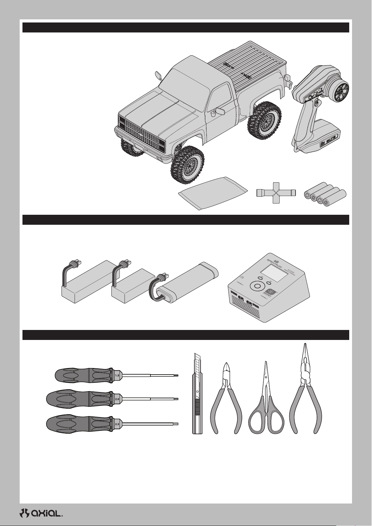
BOX CONTENTS
• Spektrum™ SLT3 3 Channel 2.4GHz Transmitter (SPMRSLT300)
• Axial® SCX10™ III Proline® ’82 Chevy® K10® RTR
- 35T Electric Motor (DYNS1216)
- 40A Smart Brushed ESC (SPMXSE1040)
- Spektrum DSMR® 3 Channel Receiver (SPMSR315)
- Water Proof Metal Gear Surface Servo, 23T (SPMS614)
- (4) AA Alkaline batteries
REQUIRED EQUIPMENT
• 2-3S Standard or “Shorty” LiPo Battery
• 5-9 Cell NiMH/NiCd battery
(IC3® Connector Required)
RECOMMENDED TOOLS
OR
• Parts Bag • Cross Wrench
• Battery charger compatible with
the chosen vehicle battery type
• (4) AA Alkaline
batteries
• Hex Drivers
(1.5, 2.0, 2.5mm)
• Hobby
Knife
4
• Side Cutter • Curved
Scissors
• Long-nose Plier
Page 5
GETTING STARTED CHECKLIST
EN
Read the manual
Familiarize yourself with the vehicle and its components
Check all screws, especially the driveshaft setscrews, for
tightness from the factory
Charge the vehicle battery
Install 4 AA batteries in the transmitter
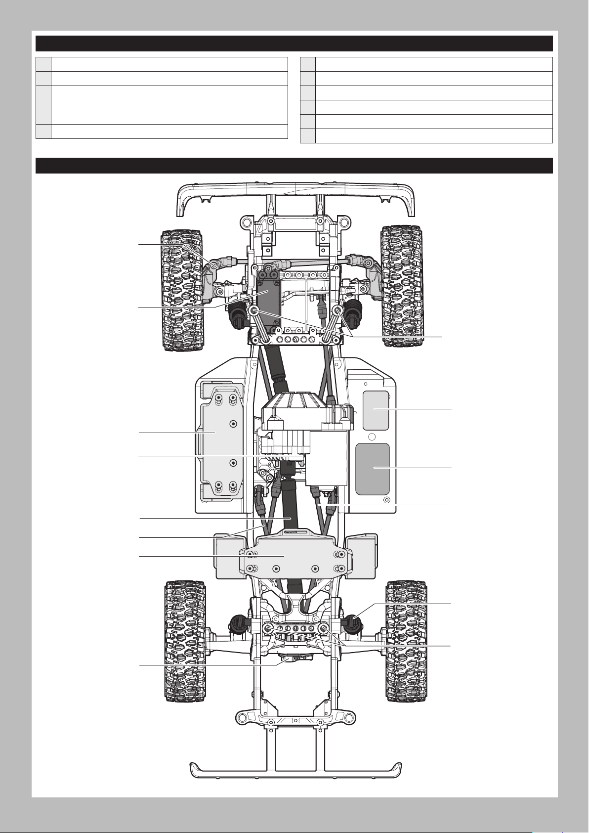
VEHICLE PARTS
Steering Knuckle
Steering Servo
Power on the transmitter
Install the vehicle battery in the vehicle
Check for proper function of the throttle and steering
Range check the radio system
Drive the vehicle, challenge yourself and have FUN!
Perform any necessary vehicle maintenance
Front Body Mount
“Shorty” Battery Tray
Transmission
Driveshaft
Upper 4-link Bar
Standard Battery Tray
Differential
(inside axle housing)
Receiver
ESC
Lower 4-link Bar
Shock Absorber
Rear Body Mount
5
Page 6
EN
CHARGE THE VEHICLE BATTERY
Follow the manufacturer’s directions for your charger to properly
charge the vehicle battery.
CAUTION: Only use chargers designed to charge the chosen
battery type. Using an incorrect charger or incorrect charger
settings could cause the battery to catch fire or explode.
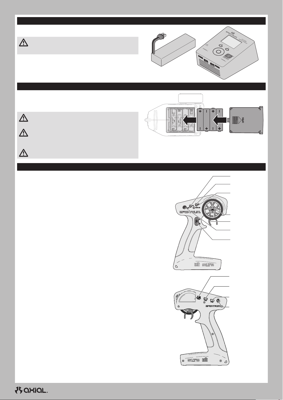
INSTALL THE TRANSMITTER BATTERIES
This transmitter requires 4 AA batteries.
1. Remove the battery cover from the transmitter.
2. Install the batteries as shown.
3. Install the battery cover.
CAUTION: NEVER remove the transmitter batteries while the
model is powered on. Loss of model control, damage, or injury
may occur.
CAUTION: If using rechargeable batteries, charge only
rechargeable batteries. Charging non-rechargeable batteries
may cause the batteries to burst, resulting in injury to persons and/or
damage to property.
CAUTION: Risk of explosion if battery is replaced by an incorrect
type. Dispose of used batteries according to national regulations.
TRANSMITTER FUNCTIONS
SPECIFICATIONS
Power Supply: 4 AA Batteries
Operating Frequency: 2.4GHz
Transmit Power: <100mw
Control Protocol: SLT
Control: Proportional Steering and Throttle/Brake with Trim Knobs,
Third Channel with 3 Position Momentary Switch
Auxiliary Functions: 3 Position Throttle Limit Switch, Steering Rate
Knob to Change Steering Travel on-the-fly, Programmable Servo Travel
for Steering and Throttle/Brake
A. Throttle Trim
Adjusts the throttle neutral point
B. Steering Trim
Adjusts the steering center point. Normally, the steering trim is
adjusted until the vehicle tracks straight.
C. LED
• Solid red lights: Indicates the power is ON and adequate battery
power
• Flashing red lights: Indicates the battery voltage is critically low.
Replace batteries
D. Steering Wheel
E. Throttle/Brake
F. Steering Rate
On-The-Fly knob for travel adjustment on the steering
G. Channel 3
3 position momentary switch, middle position is neutral
For programming press up for A button, press down for B button
H. Throttle Limit
Limits throttle output to 50/75/100%
Select 50% or 75% for less experienced drivers or when you are
driving the vehicle in a small area.
I. Throttle (TH) Servo Reversing
Move the switch to reverse the throttle channel
J. Steering (ST) Servo Reversing
Move the switch to reverse the steering channel
K. Power Button
A
B
C
D
E
F
G
H
I
J
K
6
Page 7
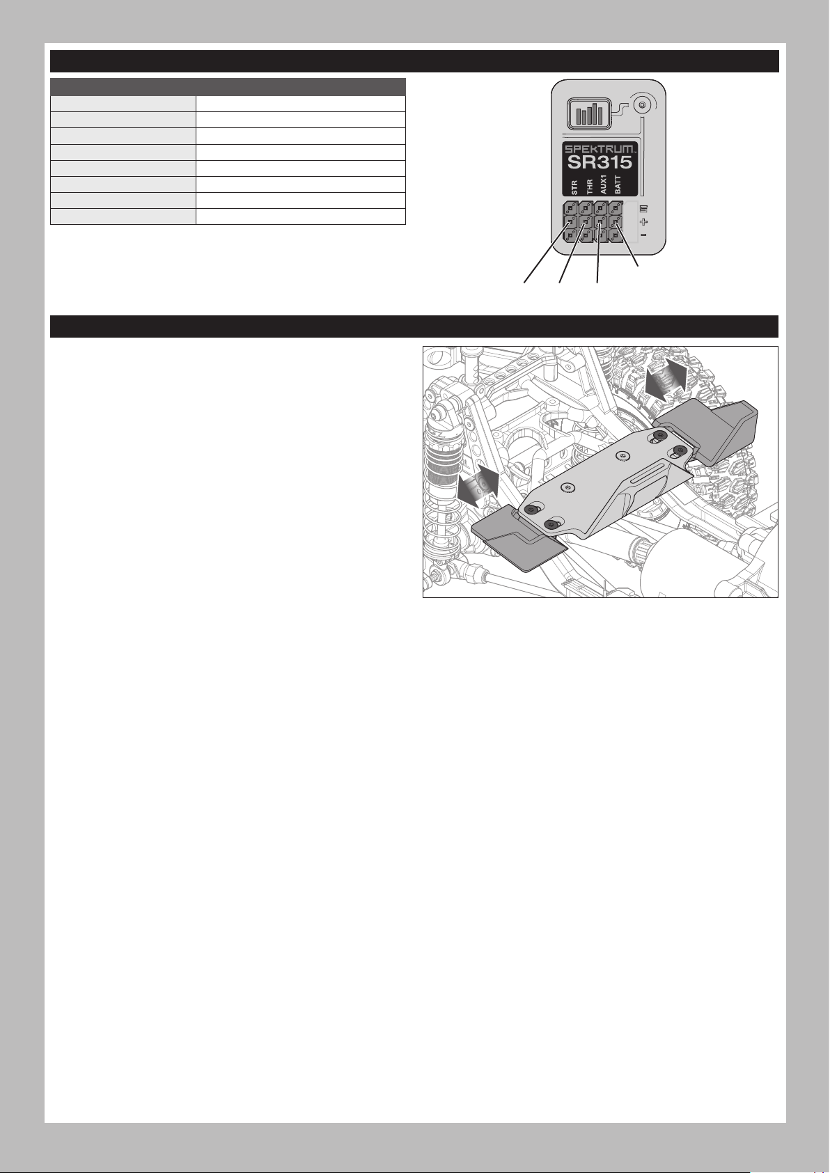
SPMSR315 DUAL PROTOCOL RECEIVER
SPECIFICATIONS
Type
Dimensions (L × W × H) 32.5 x 21.5 x 12.4mm
Antenna Length 90mm
Channels 3
Weight 6g
Band 2.4GHz
Voltage Range 3.5–9.6V
Bind Type Button
Dual
Protocol 3 Ch Receiver (SLT/DSMR)
ADJUSTING THE VEHICLE BATTERY TRAY
The battery trays may be adjusted to fit a wide range of battery sizes.
The rear battery tray is shown in the illustration. The side battery tray
is adjustable in the same manner.
To adjust the battery tray:
1. Loosen the four flathead screws shown in the illustration.
2. Slide the ends of the battery tray in or out to fit the desired battery.
3. Tighten the four flathead screws. Do not over-tighten the screws.
STR THR
EN
BATT
AUX 1
7
Page 8
EN
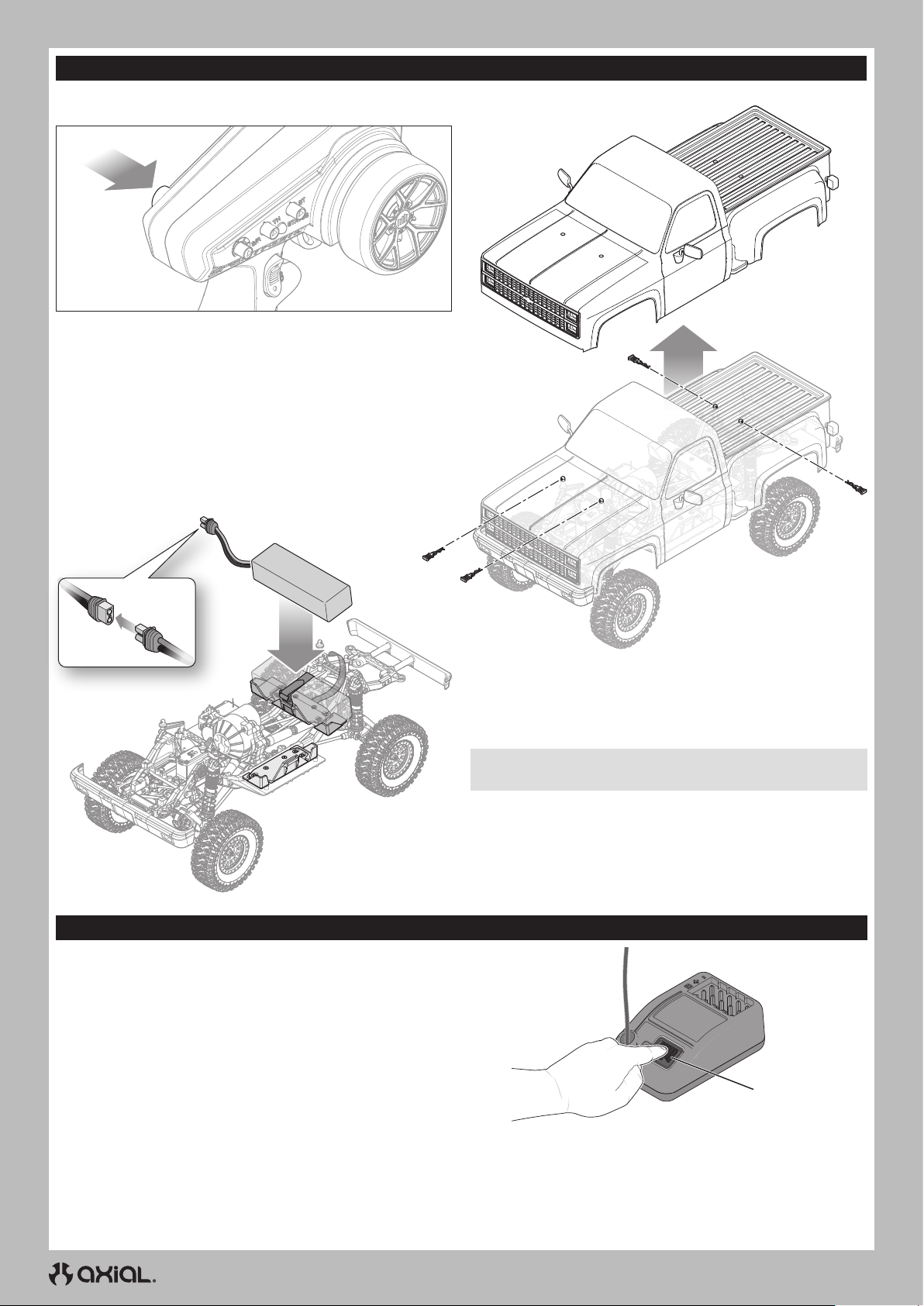
INSTALL THE VEHICLE BATTERY
The following steps show the installation of a standard size battery in the rear battery tray of the vehicle. If you wish to use a “shorty” style
battery, it should be installed in the side battery tray location.
Power
1. Power on the transmitter.
2. Remove the four body clips from the body.
3. Lift the body from the chassis.
4. Place the battery in the battery tray. The battery tray length may be
adjusted to fit the battery as described in the previous section.
BINDING
Binding is the process of programming the receiver to recognize the
GUID (Globally Unique Identifier) code of a single specific transmitter.
Failsafe:
failsafe positions during binding
You must rebind when:
Hold the steering wheel and throttle trigger in the desired
1. Press and hold the bind button.
2. Power ON the receiver. The orange LED will begin to flash.
3. Set the trims and control positions at the desired failsafe settings.
4. Power ON the SLT3 transmitter.
5. When the transmitter’s orange LED remains lit, it is connected to
SR315 receiver.
• Different failsafe positions are desired (e.g., when throttle or steering
reversing has changed).
• Binding the receiver to a different transmitter.
5. Secure the battery to the tray with the hook and loop strap.
6. Connect the battery to the ESC.
7. Re-install the body and four body clips to the chassis.
NOTICE: Always disconnect the battery from the ESC before
powering off the transmitter. Loss of vehicle control may result.
Bind Button
8
Page 9
EN
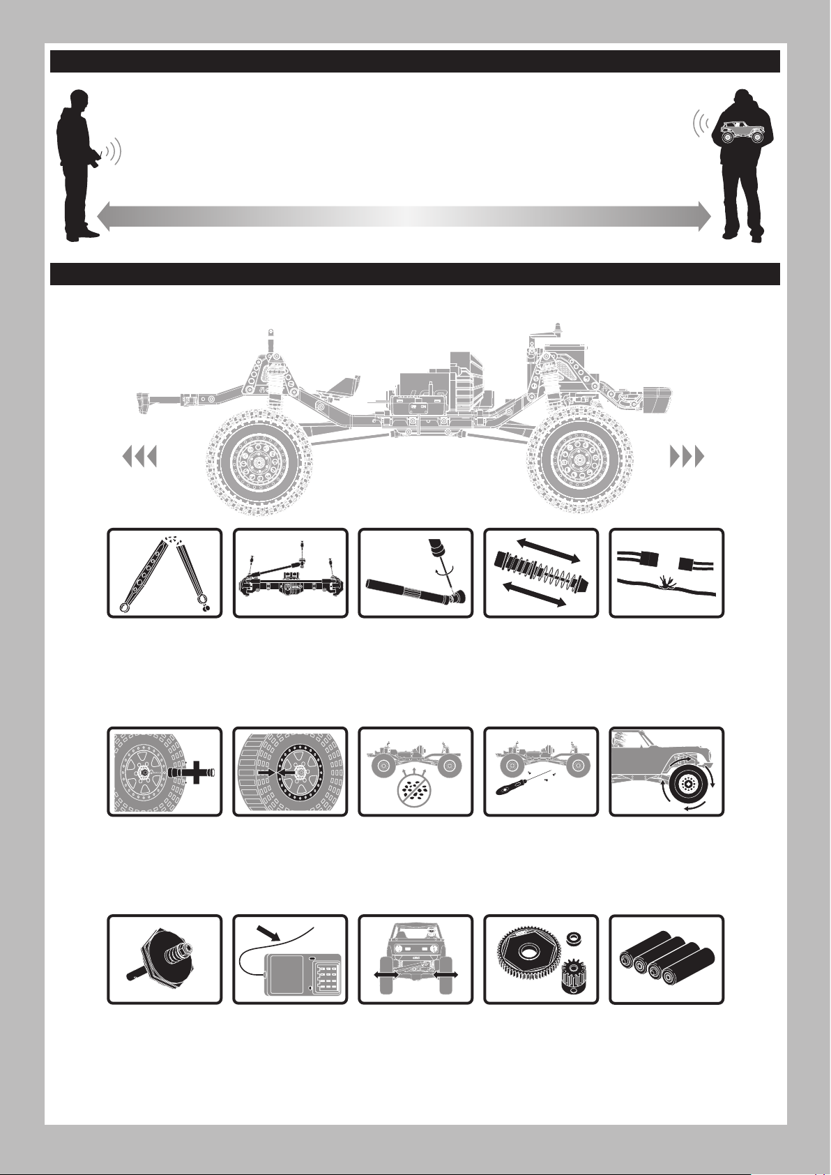
RANGE-CHECKING THE RADIO SYSTEM
The radio system should be checked before operating the vehicle to ensure proper operation and adequate range.
1. Turn on the transmitter.
2. Connect the battery in the vehicle.
3. Have a friend hold the vehicle while keeping hands and loose clothing away from moving parts.
4. Walk away until you are at the maximum planned operating distance from the vehicle.
5. Turn the steering wheel side to side and operate the throttle, both forward and reverse, checking for any
erratic behavior.
6. If any erratic behavior is exhibited, DO NOT operate the vehicle. Call customer service for assistance.
VEHICLE MAINTENANCE
Just like a full size car or truck your RC vehicle must undergo periodic maintenance in order to ensure peak performance. Preventative maintenance
will also help avoid needless breakages which could result in costly repairs. Below are some suggestions to properly maintain your vehicle.
Replace any
noticeable bent or
broken parts
Check the wheel nuts
for tightness
If applicable, check
the slipper clutch for
proper operation
Check for wear on
the ball joints in
the steering and
suspension links
(replace if necessary)
Ensure the wheel
beads are still firmly
bonded around the
entire circumference
of the rim
Check the receiver
antenna for damage
Check driveshaft
set screws and
apply thread
locking compound if
necessary
Keep the chassis free
of dirt and debris
Check the steering
operation for any
binding
Inspect shock
absorbers for smooth
dampened operation
Check for loose
screws on the chassis,
especially the knuckle,
C-hub and axle lockout
screws
Inspect the spur
and pinion gears for
damage
Check for any loose
connections or frayed
wiring
Check the driveline
for smooth, bind free
operation
Replace the
transmitter batteries
when indicated by
the transmitter, as
described in the
Transmitter Functions
section
9
Page 10
EN
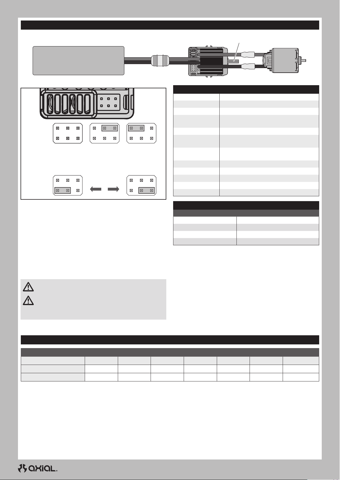
FIRMA 40A BRUSHED ESC
Battery
Mode
Battery
(BATT)
Forward/Brake/
Reverse (F/B/R)
50% Drag
Brake
Li-Po
(default)
Ni-MH
Red
Black
100% Drag Brake
(default)
To Receiver
ESC
Type Brushed
Constant/Peak 40A/180A
Resistance 0.002 Ohms
Function
Vehicle Type 1/10 on-road and off-road; 1/10 rock crawler
Operation
Battery Type/Input
Voltage
Motor Type 2S Li-Po down to 12T; 3S Li-Po down to 18T
BEC Output 6V/3A
Dimensions 46.5mm x 34mm x 28.5mm (1.8 x 1.3 x 1.1 in)
Weight 70g (2.5 oz)
Battery Connector IC3™ connector
Throttle Channel
SPECIFICATIONS
Forward/Brake/Reverse, Forward/Brake,
Forward/Reverse (Crawler Mode)
Proportional forward, proportional reverse
with braking delay, Crawler Mode
2–3 cell Li-Po/Li-Fe; 5–9 cell Ni-MH/Ni-Cd
Motor
SETUP
Throttle calibration should not be needed out of the box. However,
in order to make the throttle range of different transmitters, the
calibration of the ESC is necessary:
• Mount the ESC in an area that is well ventilated and isolated from
vibration and shock.
• Connect the ESC motor wires to the motor red-to-red and black-toblack.
• Plug the receiver into the throttle channel of the receiver.
• Before plugging the battery into the ESC, make sure your transmitter
is on and the throttle trim is set to zero.
• Connect the battery to the ESC. The vehicle will be powered on
when the battery is connected.
CAUTION: Keep all body parts and loose clothing away from
any moving parts while the battery is connected to the ESC.
CAUTION: Always connect the ESC only to a proper power
source that has the correct voltage and polarity. Incorrect voltages
or reversed polarity will damage the ESC. Damage to the ESC caused by
improper voltage or polarity is not covered under warranty.
• Test forward and reverse control using the transmitter.
OPERATION SOUND
Ni-MH/Ni-CD Battery 1 Short Beep
2S Li-Po Battery 2 Short Beeps
3S Li-Po Battery 3 Short Beeps
TO CALIBRATE THE ESC:
• Power the transmitter on and set the throttle control to neutral.
• Connect the battery to the ESC and wait 3 seconds to let the ESC
initiate a self-test and automatic throttle calibration.
• The ESC is ready to run when a long beep sound is emitted from the motor.
• Always disconnect the battery when the vehicle is not in use.
IMPORTANT: The LiPo cut-off is set to “ON” and the drag brake is
set to 100% from the factory.
SOUND INDICATOR
ESC Ready 1 Long Beep
GEAR RATIOS
SPUR/PINION GEAR RATIO CHART - LCX TRANSMISSION
12 13 14 (stock) 15 16 17 18
Portal Axles (stock) 55.1 50.9 47.2 44.1 41.3 38.9 36.7
Standard Axles (optional) 30.5 28.1 26.1 24.4 22.9 21.5 20.3
10
Page 11
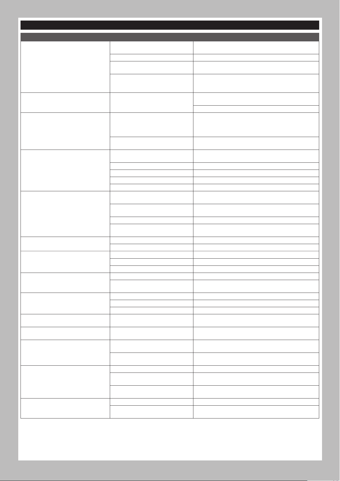
TROUBLESHOOTING
PROBLEM POSSIBLE CAUSE SOLUTION
Your transmitter and receiver are too
close together
You are near metal objects Move to an area with less metal
The system will not connect
The receiver goes into failsafe a short
distance away from the transmitter
The receiver stops responding during
operation
Vehicle does not move
Loss of vehicle control
Steering and/or throttle function is
reversed
ESC ON - No motor function, audible tone
or LED
Motor- Stops and LED blinks
Motor- Accelerates irregularly
Motor- Does not turn continuously in
response to throttle
Motor- Slows but will not stop Incorrect transmitter/ESC calibration
Steering servo- Operates; motor does not
run
Steering/motor- not functioning
Vehicle- Does not operate at full speed
The receiver is bound to a different
model memory
Your transmitter was placed into bind
mode and is no longer bound to your
receiver
Check for damage on the receiver
antenna
Low receiver battery voltage. If the
battery voltage is low, it may drop
below 3.5V momentarily, causing the
receiver to brown-out, then reconnect
Loose or damaged wires or connectors
between battery and receiver
Batteries are not installed properly in
the transmitter
Weak or no battery in the vehicle Install a freshly charged vehicle battery
Damaged motor Replace the motor
Frayed or broken wiring Replace any damaged wiring
ESC is shut down by heat protection circuit
Improper antenna placement
Weak or no batteries in the transmitter
or vehicle
Neutral or trim position is incorrect Adjust the steering trim
Receiver and/or battery not connected
properly
Servo travel is reversed at the transmitter Set the transmitter servo reversing switch to the correct position
Motor wires are not connected properly Check all motor wires for correct polarity and secure connection
Battery/connection issue Recharge/replace battery. Secure all connections
Damaged ESC Repair/replace ESC
Damaged motor Repair/replace
Low voltage protection When the ESC LED blinks, recharge/replace battery
Overheat protection
Battery issue Repair damaged wiring/replace battery
Incorrect gearing Adjust/replace gearing
Worn or damaged motor Repair/replace motor
ESC/motor damaged Repair/replace wiring or motor/ESC
Damaged motor
Incorrect transmitter/ESC calibration
Low battery voltage Recharge/replace
Wrong model memory selected on
transmitter
Receiver not bound to transmitter
Battery issue Recharge/replace
Incorrect transmitter/ESC calibration
EN
Move transmitter 8 to 12 feet away from receiver
Make sure the correct model memory is active in your
transmitter
Rebind your transmitter and receiver, and then re-calibrate
Make sure your receiver antenna is protected and located
as high as practical
Replace the receiver or contact Horizon Product Support
Charge the receiver or vehicle battery. Spektrum receivers
require at least 3.5V to operate
Check the wires and connection between the battery and
receiver. Repair or replace wires and/or connectors
Ensure the transmitter batteries are properly installed
Allow the ESC to cool down completely
Ensure the transmitter antenna is not blocked and the
receiver antenna is located properly
Install a freshly charged vehicle battery and new
transmitter batteries
Check all receiver and battery connections
When the LED blinks, let motor/ESC cool, change set up or
gearing to avoid overheating
Adjust throttle travel/other throttle settings on the
transmitter/ESC. Repeat the ESC Calibration Procedure
Test the motor apart from the vehicle system, repair/replace
motor as needed
Adjust throttle travel/other throttle settings on the
transmitter/ESC. Repeat the ESC Calibration Procedure
Select correct model settings on your transmitter, refer to
transmitter and/or receiver manual
Bind transmitter to receiver, refer to transmitter and/or
receiver manual
Adjust throttle travel/other throttle settings on the
transmitter/ESC. Repeat the ESC Calibration Procedure
11
Page 12
EN
LIMITED WARRANTY
What this Warranty Covers
Horizon Hobby, LLC, (Horizon) warrants to the original purchaser that the
product purchased (the “Product”) will be free from defects in materials
and workmanship for a period of 2 years from the date of purchase.
What is Not Covered
This warranty is not transferable and does not cover (i) cosmetic damage,
(ii) damage due to acts of God, accident, misuse, abuse, negligence,
commercial use, or due to improper use, installation, operation or
maintenance, (iii) modification of or to any part of the Product, (iv)
attempted service by anyone other than a Horizon Hobby authorized
service center, (v) Product not purchased from an authorized Horizon
dealer, or (vi) Product not compliant with applicable technical regulations
or (vii) use that violates any applicable laws, rules, or regulations.
OTHER THAN THE EXPRESS WARRANTY ABOVE, HORIZON MAKES NO
OTHER WARRANTY OR REPRESENTATION, AND HEREBY DISCLAIMS
ANY AND ALL IMPLIED WARRANTIES, INCLUDING, WITHOUT
LIMITATION, THE IMPLIED WARRANTIES OF NON-INFRINGEMENT,
MERCHANTABILITY AND FITNESS FOR A PARTICULAR PURPOSE. THE
PURCHASER ACKNOWLEDGES THAT THEY ALONE HAVE DETERMINED
THAT THE PRODUCT WILL SUITABLY MEET THE REQUIREMENTS OF
THE PURCHASER’S INTENDED USE.
Purchaser’s Remedy
Horizon’s sole obligation and purchaser’s sole and exclusive remedy
shall be that Horizon will, at its option, either (i) service, or (ii) replace,
any Product determined by Horizon to be defective. Horizon reserves
the right to inspect any and all Product(s) involved in a warranty
claim. Service or replacement decisions are at the sole discretion of
Horizon. Proof of purchase is required for all warranty claims. SERVICE
OR REPLACEMENT AS PROVIDED UNDER THIS WARRANTY IS THE
PURCHASER’S SOLE AND EXCLUSIVE REMEDY.
Limitation of Liability
HORIZON SHALL NOT BE LIABLE FOR SPECIAL, INDIRECT,
INCIDENTAL OR CONSEQUENTIAL DAMAGES, LOSS OF PROFITS OR
PRODUCTION OR COMMERCIAL LOSS IN ANY WAY, REGARDLESS OF
WHETHER SUCH CLAIM IS BASED IN CONTRACT, WARRANTY, TORT,
NEGLIGENCE, STRICT LIABILITY OR ANY OTHER THEORY OF LIABILITY,
EVEN IF HORIZON HAS BEEN ADVISED OF THE POSSIBILITY OF SUCH
DAMAGES. Further, in no event shall the liability of Horizon exceed the
individual price of the Product on which liability is asserted. As Horizon
has no control over use, setup, final assembly, modification or misuse,
no liability shall be assumed nor accepted for any resulting damage
or injury. By the act of use, setup or assembly, the user accepts all
resulting liability. If you as the purchaser or user are not prepared to
accept the liability associated with the use of the Product, purchaser
is advised to return the Product immediately in new and unused
condition to the place of purchase.
Law
These terms are governed by Illinois law (without regard to conflict of law
principals). This warranty gives you specific legal rights, and you may also
have other rights which vary from state to state. Horizon reserves the right
to change or modify this warranty at any time without notice.
WARRANTY SERVICES
Questions, Assistance, and Services
Your local hobby store and/or place of purchase cannot provide
warranty support or service. Once assembly, setup or use of the Product
has been started, you must contact your local distributor or Horizon
directly. This will enable Horizon to better answer your questions and
service you in the event that you may need any assistance. For questions
or assistance, please visit our website at www.horizonhobby.com,
submit a Product Support Inquiry, or call the toll free telephone number
referenced in the Warranty and Service Contact Information section to
speak with a Product Support representative.
Inspection or Services
If this Product needs to be inspected or serviced and is compliant in
the country you live and use the Product in, please use the Horizon
Online Service Request submission process found on our website
or call Horizon to obtain a Return Merchandise Authorization (RMA)
number. Pack the Product securely using a shipping carton. Please
note that original boxes may be included, but are not designed to
withstand the rigors of shipping without additional protection. Ship
via a carrier that provides tracking and insurance for lost or damaged
parcels, as Horizon is not responsible for merchandise until it arrives
and is accepted at our facility. An Online Service Request is available
at http://www.horizonhobby.com/content/service-center_renderservice-center. If you do not have internet access, please contact
Horizon Product Support to obtain a RMA number along with
instructions for submitting your product for service. When calling
Horizon, you will be asked to provide your complete name, street
address, email address and phone number where you can be reached
during business hours. When sending product into Horizon, please
include your RMA number, a list of the included items, and a brief
summary of the problem. A copy of your original sales receipt must be
included for warranty consideration. Be sure your name, address, and
RMA number are clearly written on the outside of the shipping carton.
NOTICE: Do not ship Li-Po batteries to Horizon. If you have any
issue with a Li-Po battery, please contact the appropriate Horizon
Product Support office.
Warranty Requirements
For Warranty consideration, you must include your original sales
receipt verifying the proof-of-purchase date. Provided warranty
conditions have been met, your Product will be serviced or replaced
free of charge. Service or replacement decisions are at the sole
discretion of Horizon.
Non-Warranty Service
Should your service not be covered by warranty, service will be
completed and payment will be required without notification or
estimate of the expense unless the expense exceeds 50% of the retail
purchase cost. By submitting the item for service you are agreeing
to payment of the service without notification. Service estimates
are available upon request. You must include this request with your
item submitted for service. Non-warranty service estimates will be
billed a minimum of 1/2 hour of labor. In addition you will be billed for
return freight. Horizon accepts money orders and cashier’s checks,
as well as Visa, MasterCard, American Express, and Discover cards.
By submitting any item to Horizon for service, you are agreeing to
Horizon’s Terms and Conditions found on our website http://www.
horizonhobby.com/content/service-center_render-service-center.
ATTENTION: Horizon service is limited to Product compliant in
the country of use and ownership. If received, a non-compliant
Product will not be serviced. Further, the sender will be responsible
for arranging return shipment of the un-serviced Product, through
a carrier of the sender’s choice and at the sender’s expense.
Horizon will hold non-compliant Product for a period of 60 days from
notification, after which it will be discarded.
10/15
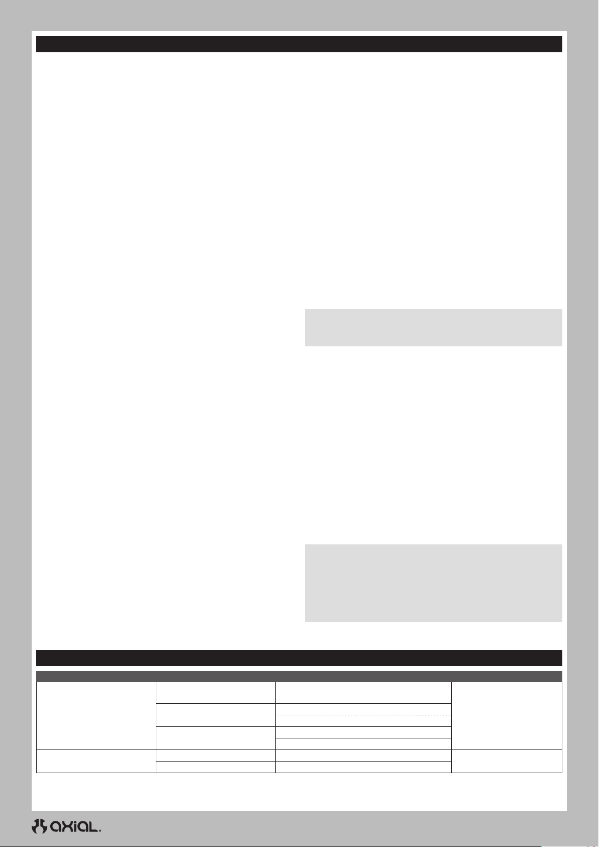
WARRANTY AND SERVICE CONTACT INFORMATION
COUNTRY OF PURCHASE HORIZON HOBBY CONTACT INFORMATION ADDRESS
United States of America
European Union
Horizon Service Center
(Repairs and Repair Requests)
Horizon Product Support
(Product Technical Assistance)
Sales
servicecenter.horizonhobby.com/RequestForm/
[email protected]
877-504-0233
[email protected]
800-338-4639
12
2904 Research Rd
Champaign, IL 61822
Hanskampring 9
D 22885 Barsbüttel, Germany
Page 13
FCC INFORMATION
FCC ID: BRWSPMSLT300
FCC ID: BRWSRIRVINGV1
SUPPLIER’S DECLARATION OF CONFORMITY
Axial SCX10 III Proline 82 Chevy K10 RTR (AXI03029)
This device complies with part 15 of the FCC Rules. Operation is
subject to the following two conditions: (1) This device may not
cause harmful interference, and (2) this device must accept
any interference received, including interference that may cause
undesired operation.
CAUTION: changes or modifications not expressly approved
by the party responsible for compliance could void the user’s
authority to operate the equipment.
NOTE: This equipment has been tested and found to comply with the
limits for a Class B digital device, pursuant to part 15 of the FCC Rules.
These limits are designed to provide reasonable protection against
harmful interference in a residential installation. This equipment
generates, uses and can radiate radio frequency energy and, if not
installed and used in accordance with the instructions, may cause
IC INFORMATION
CAN ICES-3 (B)/NMB-3(B)
IC: 6157A-SPMSLT300
IC: 6157A-SRIRVINGV1
This device contains license-exempt transmitter(s)/receivers(s)
that comply with Innovation, Science, and Economic Development
Canada’s license-exempt RSS(s). Operation is subject to the following
2 conditions:
EN
harmful interference to radio communications. However, there is no
guarantee that interference will not occur in a particular installation. If
this equipment does cause harmful interference to radio or television
reception, which can be determined by turning the equipment off and
on, the user is encouraged to try to correct the interference by one or
more of the following measures:
• Reorient or relocate the receiving antenna.
• Increase the separation between the equipment and receiver.
• Connect the equipment into an outlet on a circuit different from that
to which the receiver is connected.
• Consult the dealer or an experienced radio/TV technician for help.
Horizon Hobby, LLC
2904 Research Rd.,
Champaign, IL 61822
Email: [email protected]
Web: HorizonHobby.com
1. This device may not cause interference.
2. This device must accept any interference, including interference
that may cause undesired operation of the device.
COMPLIANCE INFORMATION FOR THE EUROPEAN UNION
EU COMPLIANCE STATEMENT:
Axial SCX10 III Proline 82 Chevy K10 RTR (AXI03029)
Hereby, Horizon Hobby, LLC declares that the device is in
compliance with the following: EU Radio Equipment Directive 2014/53/
EU; RoHS 2 Directive 2011/65/EU; RoHS 3 Directive - Amending 2011/65/
EU Annex II 2015/863.
The full text of the EU declaration of conformity is available at the
following internet address: https://www.horizonhobby.com/content/
support-render-compliance.
Wireless Frequency Range and Wireless Output Power
Transmitter
2403.0 - 2480.0 MHz
16.3 dBm
Receiver
2404-2476 MHz
-1.33dBm
EU Manufacturer of Record:
Horizon Hobby, LLC
2904 Research Road
Champaign, IL 61822 USA
EU Importer of Record:
Horizon Hobby, GmbH
Hanskampring 9
22885 Barsbüttel Germany
WEEE NOTICE:
This appliance is labeled in accordance with European
Directive 2012/19/EU concerning waste of electrical and
electronic equipment (WEEE). This label indicates that this
product should not be disposed of with household waste. It
should be deposited at an appropriate facility to enable
recovery and recycling.
13
Page 14
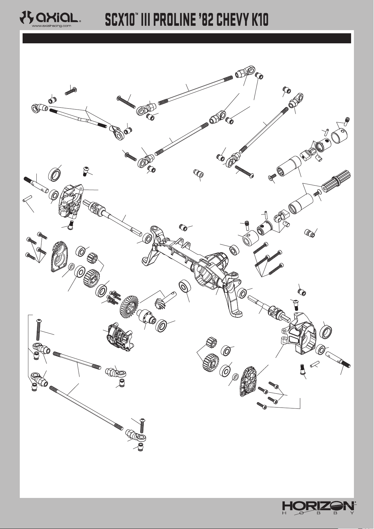
EXPLODED VIEWS // EXPLOSIONSZEICHNUNGEN // VUES ÉCLATÉES // VISTE ESPLOSE
EXPLODED VIEWS // EXPLOSIONSZEICHNUNGEN // VUES ÉCLATÉES // VISTE ESPLOSE
FRONT AXLE
VORDERACHSE
ESSIEU AVANT
ASSALE ANTERIORE
AXI234004
AXI234035
AXI234035
AXI234006
AXI234004
AXI234004
AXI234035
AXI234004
AXI234006
AX31028
AX31148
AXI234004
AXI235109
AXI234010
AXI234004
AXI235109
AXA120
AXI234006
AXI234006
AXI03029
AXI232017
AXI232008
AXA1221
AX30165
AXI235014
AXI232018
AXI234004
AX31403
AXA1230
AXI237009
AXA120
AX31403
AXA1221
AX31066
AXI232026
AXI232006
AXI232007
AX31406
AXI234004
AXI232027
AXA1221
AXI232003
AXI232002
AX31407
AX31406
AXI234006
AXI234003
AXI234004
AXA1221
AXI232022
AXA120
AXA0286
AXI232017
AX31028
AXI235016
AXA1221
AXI232027
AXI232017
AXA144
AXA144
AXI234003
AX31148
AXI234004
AX31403
AXA1230
AXI234006
AXI234035
AXI234006
AXI234004
AXI234006
AXI235110
AXI234004
AXI232007
50
AXI232018
AXA1221
AXI237009
AXI232006
AXI235014
AX30165
AX31403
AXA1221
AXI232008
Page 15
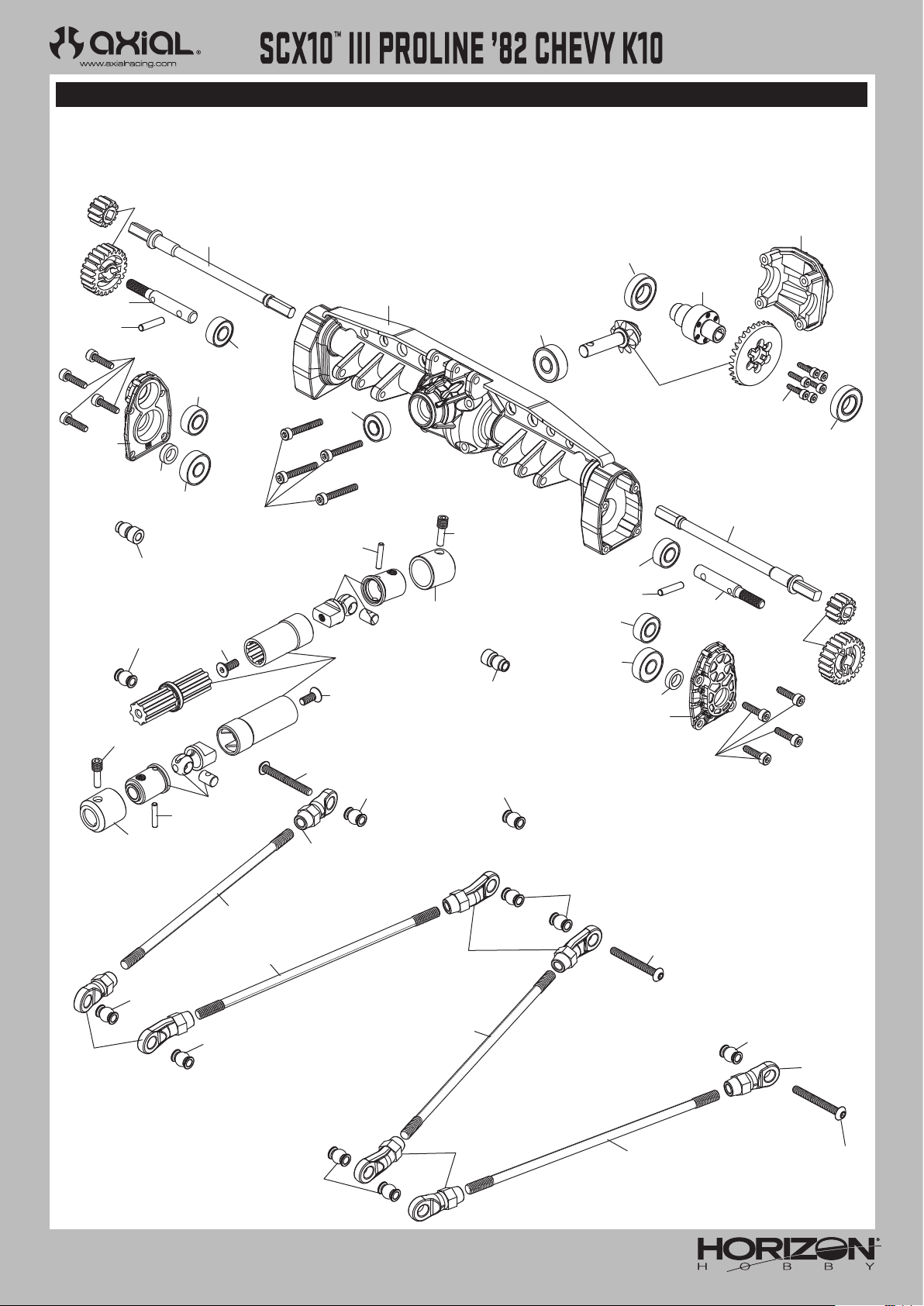
EXPLODED VIEWS // EXPLOSIONSZEICHNUNGEN // VUES ÉCLATÉES // VISTE ESPLOSE
REAR AXLE
HINTERACHSE
ESSIEU ARRIÈRE
ASSALE POSTERIORE
AXI232007
AXI03029
AXI232008
AX30165
AXI232023
AXI235014
AXI232018
AXI234003
AXI234004
AXI232028
AXA1221
AXI237009
AXA144
AXA1221
AXI235016
AXA1221
AX31028
AX31148
AXI232023
AXI232017
AXI232017
AXA0286
AX31407
AX31406
AXA1221
AX30165
AXA1221
AXI237009
AXI232003
AXI232008
AXI232026
AXI232002
AX31006
AX31406
AXI232028
AXI232007
AXA0286
AXI234006
AXI232017
AXI234004
AX31028
AX31148
AXI234035
AXI234035
AXI234004
AXA120
AXI234006
AXA144
AXI234004
AXI234006
AXI234035
AXI234003
AXI234004
AXI232018
AXI232023
AXI235014
AXI234004
AXA120
AXI234004
AXI234006
AXI234004
AXI234006
51
AXI234035
AXA120
Page 16
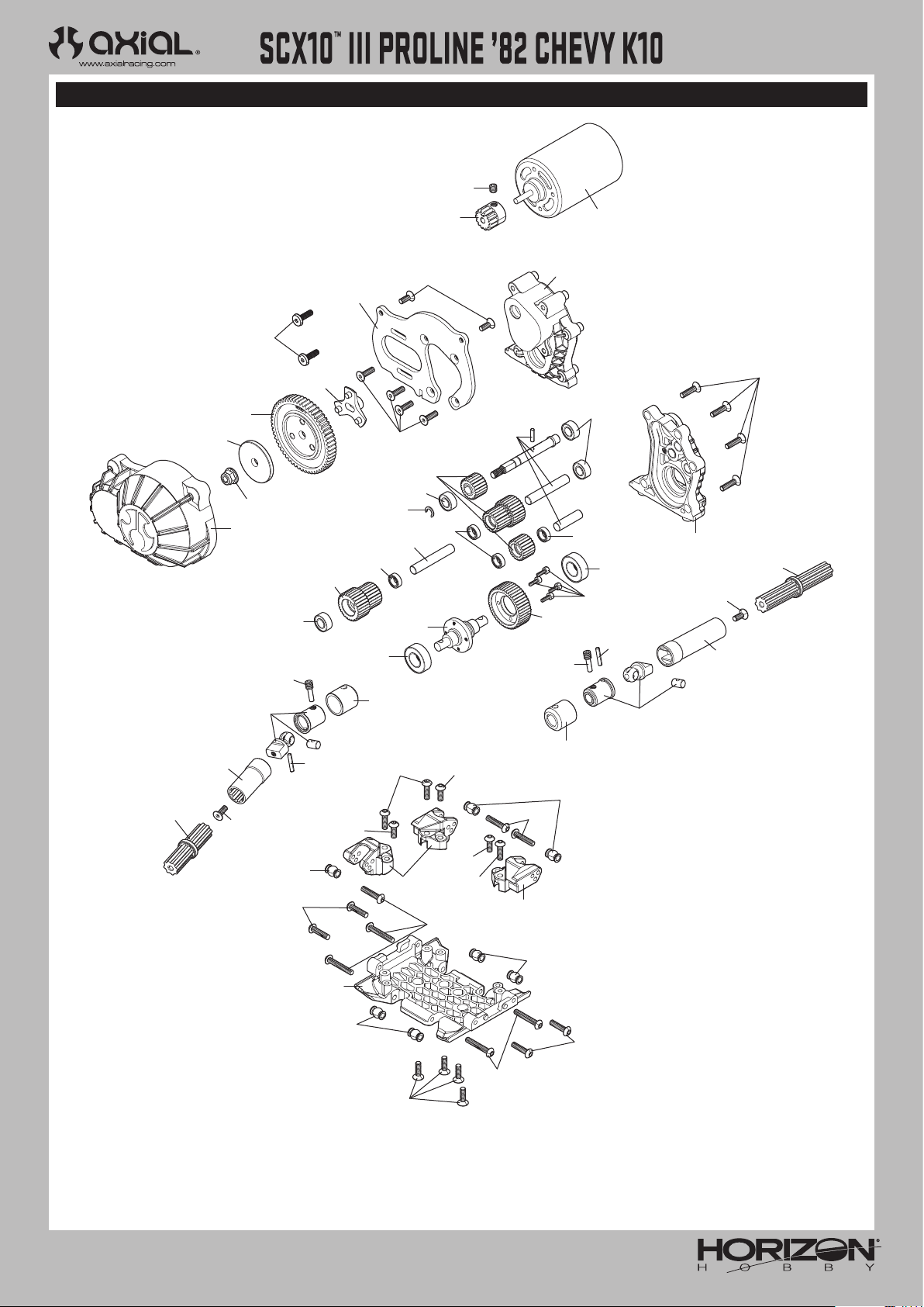
EXPLODED VIEWS // EXPLOSIONSZEICHNUNGEN // VUES ÉCLATÉES // VISTE ESPLOSE
TRANSMISSION
GETRIEBE
TRANSMISSION
TRASMISSIONE
AXA291
AXI03029
AXI232065
AXI232067
AXA0109
AX31250
AXI232064
AXA0286
AX31148
AXI232067
AXI232068
AXA1218
AXI232066
AXI236136
AXI232069
AXA1213
AXA1225
AXA144
AX31185
AXI232068
AXA1218
AXA1213
AXI232070
AXI232017
AX30725
AXI232069
AXI232064
AXI232068
AXA0286
DYNS1216
AXA1218
AXA1213
AXA1225
AXA0013
AX31028
AX31148
AXA146
AXI232064
AXI232017
AXA144
AXI232017
AXI232017
AXI232017
AXA144
AXI234004
AXA116
AXI231047
AX31028
AXA114
AXI234004
AXA115
AXI231047
AX31185
AXI232017
AXA114
AXI234004
AXA118
AXA114
AXA115
AXI231047
AXA118
AXI234004
AXA116
AXA118
52
Page 17
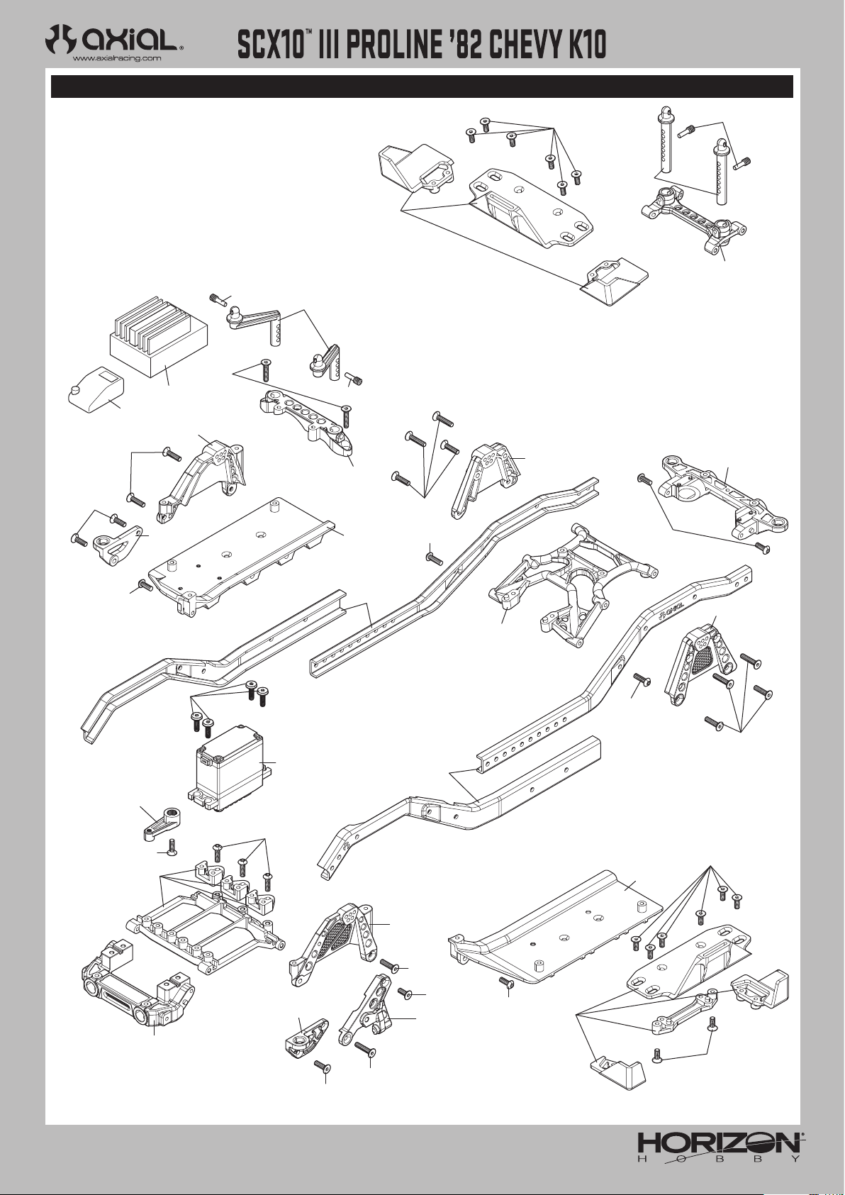
EXPLODED VIEWS // EXPLOSIONSZEICHNUNGEN // VUES ÉCLATÉES // VISTE ESPLOSE
CHASSIS
KAROSSERIE
CHÂSSIS
TELAIO
AXI231008
AXA144
AXI230048
AXI03029
AXA0286
AXI231021
AXA146
AX31185
AXA144
SPMXSE1040
SPMSR315
AXI231017
AXI231016
AXA0109
AXA146
AXA0286
AXI230048
AXA0286
AXI231021
AXI231049
AXI231015
AXA146
AXA114
AXI231049
AXI231017
AXI231048
AXA114
AXI231017
AXA114
AXI231012
AX31185
AXI231048
AXI231016
AXA115
SPMS614
AXI231016
AX31185
AXA146
AXI231015
AXI231017
AXA146
AXA144
AXI231046
AXA144
AXA146
AXI235167
AXI231049
AXI231008
AXI235167
53
Page 18
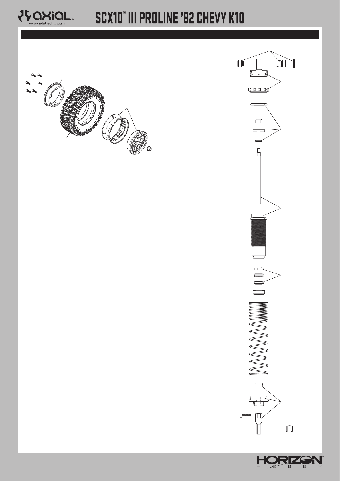
EXPLODED VIEWS // EXPLOSIONSZEICHNUNGEN // VUES ÉCLATÉES // VISTE ESPLOSE
AXI03029
WHEELS AND TIRES
REIFEN UND RÄDER
ROUES ET PNEUS
RUOTE E PNEUMATICI
PRO278100
PRO1014214
PRO278100
SHOCK ABSORBERS
STOSSDÄMPFER
AMORTISSEURS
AMMORTIZZATORI
PRO634301
PRO634300
PRO634301
PRO634300
PRO634301
PRO634302
PRO634301
54
Page 19
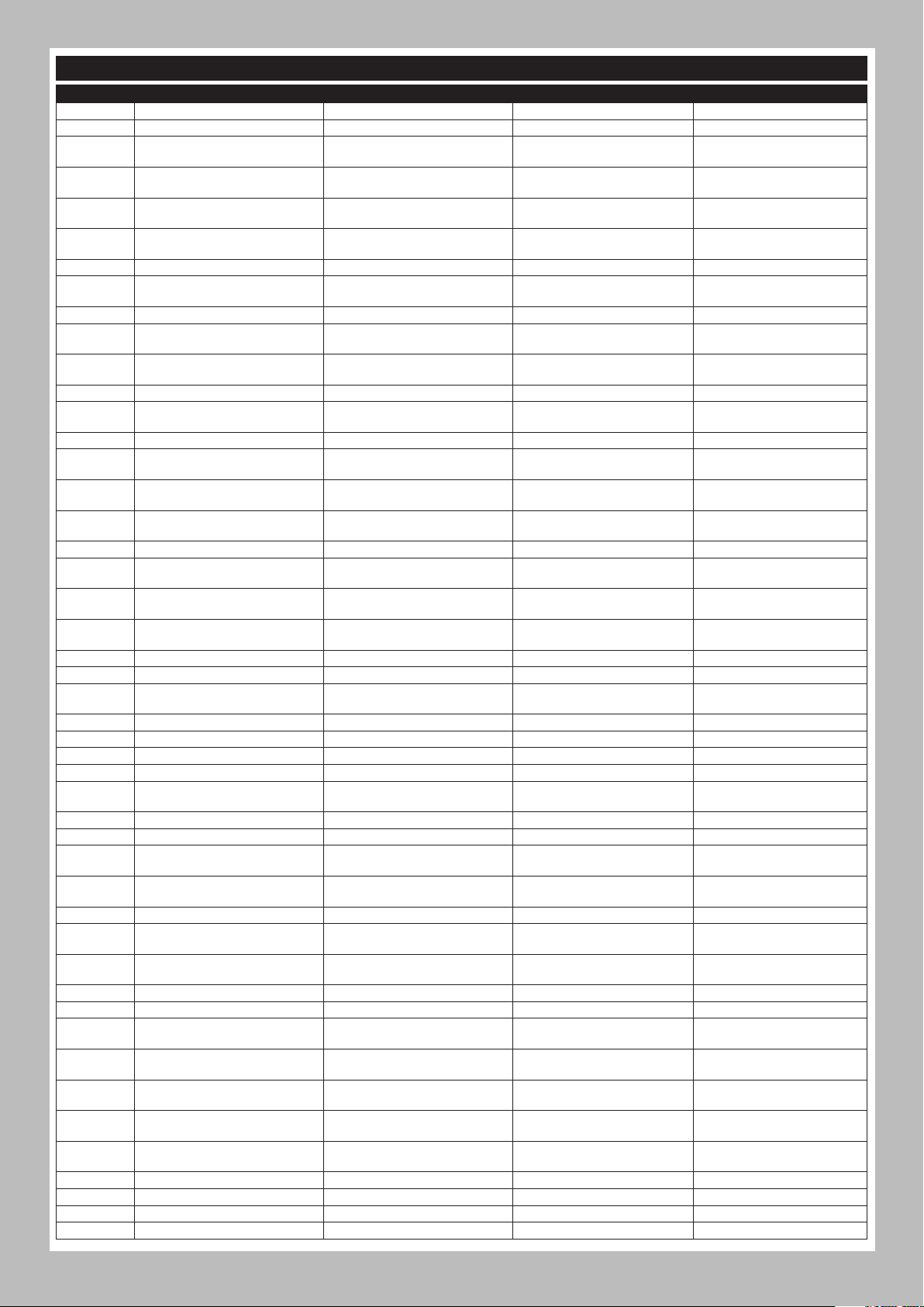
PARTS LISTS // TEILELISTEN // LISTE DES PIÈCES // ELENCO COMPONENTI
Part # Description Beschreibung Description Descrizione
ARAC9759
AX31028 2 x 11mm Pin Stift 2 x 11mmmm (6) Axe 2 x 11mm (6) Perno 2 x 11mm (6)
AXI230048 Body Post Set: SCX10 III BC Gehäusestangensatz: SCX10 III BC
AXI231008 BatteryTray Set/Strap: SCX10III Akkuhalterungsätze und Riemen
AXI231009 Upper Center Lnk Mnts: SCX10III Obere mittige Gestängehalterungen
AXI231010 Cntr Trans Skid Plate: SCX10III Mittiges Getriebe-Gleitbrett
AXI231011 Str Mnt Chassis Brace: SCX10II Lenkhalterung Karosseriestrebe Support de châssis de direction Sostegno telaio supporto sterzo
AXI231012 Servo Horn, Metal 23T: SCX10III Servohorn, Metall 23T
AXI231015 Frame Rail Set: SCX10III Rahmenschienensatz Ensemble de rails du cadre Set guida telaio
AXI231016 Bmpr/Bdy Mnts Chs FR/RR:SCX10II
AXI231017 Shktwrs&Pnhrd Mnts Fr/RRSCX10II
AXI231018 Receiver Box: SCX10III Empfängerbox Boîtier de récepteur Scatola ricevitore
AXI231021 Upper Shk Twr Braces: SCX10III Obere Stoßdämpferbrückenstreben
AXI231046 Panhard Mount, Metal: SCX10 III Panhard-Halterungen Supports Panhard Supporti Panhard
AXI231047 Skd Plt &Upr Lnk Mnt:SCX10III B
AXI231048 Servo Mnt Brace FR: SCX10III BC
AXI231049 Side Plate&Rr Brace: SCX10III B
AXI232002 6-Bolt Differental Locker 6-Schrauben-Differenzial-Sicherung Blocage différentiel à 6 boulons Blocco differenziale 6 bulloni
AXI232003 6 Bolt Heavy Duty Gear Set
AXI232017 Wild Boar Driveshaft Set: UTB Wild Boar-Antriebswellensatz: UTB
AXI232018 12mm Hex Pin and Spacer (4): UTB
AXI232024 AR45 Axl Hsng(Fr)SCX10III AR45 Achsgehäuse, Front AR45 Carter d’essieu avant AR45 Allogg assale ant
AXI232025 AR45 Axl Hsng (Rr)SCX10III AR45 Achsgehäuse, Heck AR45 Carter d’essieu arrière AR45 Allogg assale post
AXI232033 InputMtlGears 27,20,34T:SCX10II
AXI232059 AR45 C-Hub (L-R): SCX10 AR45 C-Hub AR45 Moyeu de support AR45 Supporto mozzo
AXI232060 AR45 Knuckle (L-R): SCX10 III AR45 Lenkrolle AR45 Rotule de direction AR45 Fuso a snodo
AXI232061 AR45 Unvrsl Axles (2): SCX10 II AR45 Universalachsensatz AR45 Ensemble d’essieux universels AR45 Set assale univ
AXI232062 AR45 Strght Axles (2): SCX10 II AR45 Gerade Achse (2) AR45 Essieu droit (2) AR45 Assale dritto (2)
AXI232064 Gear Cover & Trans Housing: LCX
AXI232065 Spur Gear 56T 32P: LCXU Stirnrad, 56T, 32P: LCXU
AXI232066 Motor Plate: LCXU Motorplatte: LCXU Plaque moteur: LCXU Piastra motore: LCXU
AXI232067 Slipper Elimintr Hub&Plate: LCX
AXI232068 Transmission Metal Gear Set:LCX Metallgetriebesatz: LCX
AXI232069 Transmission Shaft Set: LCXU Getriebewellensatz: LCXU
AXI232070 Trans Center Output Shaft: LCXU Transzentrale Antriebswelle: LCXU
AXI233003 Shock O-Ring Set: UTB
AXI233009 Spring 13x70mm 2.0 lbs/in,Yellow)2) Feder 13 x 70 mm 2 lbs/in Gelb (2) Ressort 13 x 70 mm 2 lb/po jaune (2) Molla 13 x 70 mm 2 lbs/in Giallo (2)
AXI233031 Shock Part Composite:SCX10III B Stoßdämpferteile, gegossen Pièces de l’amortisseur moulées Parti ammortizzatore stampate
AXI233032 Alum Shck Bdy11x39.5:SCX10III B
AXI234003 Pvt Ball,Stainless12.75mm(4):UTB
AXI234004 Susp Pvt Ball, Stainless 7.5mm
AXI234006 HD Rod Ends M4 20pcs: UTB
AXI234035 Susp Link Set 313WB: SCX10III B
AXI235014 M2.5 x 10mm, Cap Head Screw (10 Inbusschraube, M2,5 x 10mm (10)
AXI235099 M2.5 x 10mm, Button Head (10) Rundkopfschraube, M2,5 x 10mm (10) Vis à tête bombée, M2,5 x 10mm (10) Vite a testa tonda M2,5 x 10mm (10)
AXI235109 M3 x 14mm, Button Head Screw(10 Rundkopfschraube, M3 x 14mm (10) Vis à tête bombée, M3 x 14mm (10) Vite a testa tonda M3 x 14mm (10)
AXI235110 M3 x 16mm, Button Head Screw(10 Rundkopfschraube, M3 x 16mm (10) Vis à tête bombée, M3 x 16mm (10) Vite a testa tonda M3 x 16mm (10)
AR722305 Flat Head Screw 3x5mm Sechskant-Flachkopfschraube, M3 x 5mm Douille à six pans à tête plate M3 x 5mm Vite a testa piana esagonale M3 x 5mm
Stoßstange/Gehäusehalterung
Karosserie Front/Heck
Stoßdämpferbrücken und PanhardHalterungen Front/Heck
Gleitbrett & Obere
Verbindungshalterung:SCX10III B
Servohalterungsstrebe vorne:
SCX10III BC
Seitenplatte & Strebe hinten:
SCX10III B
6-Schrauben-SchwerlastZahnradsatz
12-mm-Sechskantstift und
Abstandhalter (4): UTB
Metallgetriebe Eingabe 27T, 20T
und 34T
Fahrwerkabdeckung & TransGehäuse: LCX
Slipper-Eliminator-Nabe & -Platte:
LCX
O-Ring-Satz für den Stoßdämpfer:
UTB
Gewinde-Stoßdämpfergehäuse
Alum 11 x 39,5 mm
Kugelzapfen, Edelstahl 12,75 mm
(4): UTB
Kugelzapfen für Federung, Edelstahl
7,5 mm
Schwerlast-Stangenköpfe M4 (20):
UTB
Aufhängungsverbindungssatz
313WB: SCX10III B
Ens poteaux carrosserie: SCX10
III BC
Ensembles de supports de batterie
avec sangle
Supports pour tringlerie centrale
supérieure
Plaque de protection pour
transmission centrale
Renvoi de commande de servo,
métal 23T
Châssis avec supports de parechocs et de carrosserie AV/AR
Tours d’amortisseurs et supports
Panhard AV/AR
Supports de tours d’amortisseurs
supérieures
Plq trans et sup tringlerie centr
sup: SCX10III B
Support Servo FR: SCX10III BC
Plaque latérale et support AR:
SCX10III B
Ensemble d’engrenages haute
résistance à 6 boulons
Ensemble d’arbres de transmission
Wild Boar : UTB
Broche hexagonale 12mm et
entretoise (4) : UTB
Engrenages métalliques d’entrée
27T, 20T et 34T
Cache d’engrenageet carter
transmission: LCX
Engrenage roue droite, 56T, 32P: LCXU
Moyeu et plaque de sabot
éliminateur: LCX
Ensemble de boîte de transmission
métallique: LCX
Ensemble arbre de transmission: LCXU
Arbre sortie transmis centrale:
LCXU
Ensemble de joints toriques
d’amortisseur : UTB
Corps d’amortisseur fileté
aluminium 11 x 39,5 mm
Rotule, acier inoxydable 12,75mm
(4) : UTB
Rotule de suspension, acier
inoxydable 7,5mm
Embouts de bielle haute résistance
M4 (20) : UTB
Jeu de bras de
suspension313WB: SCX10III B
Vis d’assemblage creuse, M2,5 x 10mm (10)
Set supporti scocca: SCX10 III BC
Fascette e set supporto batteria
Supporti braccetti centrali
superiori
Piastra proteggi trasmissione
centrale
Squadretta servo, Metallo 23T
Telaio supporti carrozzeria/
ammortizzatore FR/RR
Torre ammortizzatore e supporti
Panhard FR/RR
Sostegni torre ammortizzatore
superiori
Sottoscocca & supporti bracci
superiori: SCX10III B
Bracci supporto servo ant:
SCX10III BC
Piastre laterali e rinforzi
posteriori: SCX10III B
Set ingranaggio impieghi gravosi
6 bulloni
Set albero di trasmissione Wild
Boar: UTB
Distanziale e perno esagonale
12mm (4): UTB
Ingranaggi in metallo ingresso
27T, 20T e 34T
Carter e coperchio trasmissione:
LCX
Corona, 56T, 32P: LCXU
Piastra e mozzo elimina
scorrimento: LCX
Set ingr trasmissione metallo:LCX
Set alberi trasmissione: LCXU
Albero uscita trasmissione
centrale: LCXU
Set O-Ring ammortizzatore: UTB
Scocca ammortizzatore filettata
in alluminio 11x39,5 mm
Pivot ball, inossidabile, 12,75mm
(4): UTB
Pivot ball sospensioni,
indossabile, 7,5mm
Teste a snodo per impiego
gravoso M4 (20): UTB
Set bracci sospensioni 313WB:
SCX10III B
Vite a testa cilindrica M2,5 x 10mm (10)
5555
Page 20
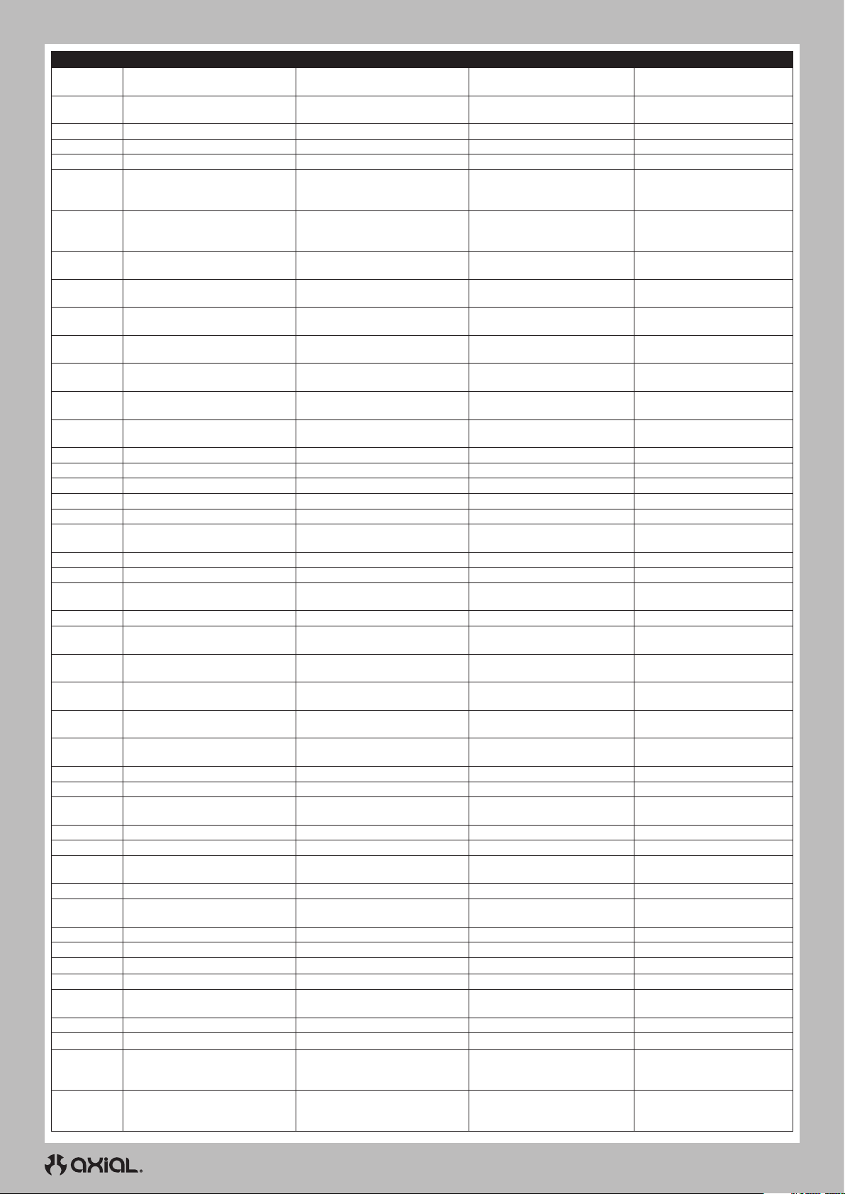
Part # Description Beschreibung Description Descrizione
AXI235178 M3 x 14mm, Flat Head Screw (10)
AXI235230 M2.5 x 18mm Cap Head Screw (10) Inbusschraube, M2,5 x 18mm (10)
AXI236136 C-Clip, 5mm (10) C-Clip, 5mm (10) C-Clip, 5mm (10) C-Clip, 5mm (10)
AXI236172 Screw Shaft M3x2.0x12mm Schraubenschaft M3x2,0x12mm Tige de visM3x2x12mm Albero filettato M3x2x12mm
AXI237009 5mmx13mmx4mm Ball Bearing (2) Lager 5mm x 13mm x 4mm (2) Roulement 5mm x 13mm x 4mm (2) Cuscinetto 5mm x 13mm x 4mm (2)
PRO1014214
PRO278100
AXIC0012 AXA120 Hex Socket Btn Hd M3x25
AXIC0013 AXA013 Cap Hd M2x6mm Blk Oxide
AXIC0114 AXA114 Hex Skt Butn Hd M3x8mm
AXIC0115 AXA115 Hex Skt Butn Head M3x10
AXIC0116 AXA116 Hex Skt Butn Hd M3x12mm
AXIC0118 AXA144 Hex Flt Hd M3x8mm Blk10
AXIC0146 AXA146 Hex Skt Flat Hd M3x12mm
AXIC0218 AXA1218 Bearing 5x10x4mm AXA1218 Lager 5x10x4mm AXA1218 Roulement 5x10x4mm AXA1218 Cuscinetto 5x10x4 mm
AXIC0221 AXA1221 Bearing 5x11x4mm AXA1221 Lager 5x11x4mm AXA1221 Roulement 5x11x4mm AXA1221 Cuscinetto 5x11x4 mm
AXIC0225 AXA1225 Bearing 8x16x5mm AXA1225 Lager 8x16x5mm AXA1225 Roulement 8x16x5mm AXA1225 Cuscinetto 8x16x5mm
AXIC0230 AXA1230 Bearing 10x15x4mm AXA1230 Lager 10x15x4mm AXA1230 Roulement 10x15x4mm AXA1230 Cuscinetto 10x15x4mm
AXIC0286 AXA0286 Screw Shaft M4x2.5x12 Schraubenschaft M4 x 2,5 x 12 mm Tige de vis M4 x 2,5 x 12mm Albero filettato M4 x 2.5 x 12mm
AXIC0291 AXA291 Set Scr M4x4mm Blk Ox(6
AXIC0392 AXA1392 E-clip E2 (10) E-Clip E2 (10) E-Clip, E2 (10) E-Clip, E2 (10)
AXIC0569 AX30569 Pinion 48P 14T Steel Ritzel 48P 14T Stahl Pignon 48P 14T en acier Pignone 48P 14T acciaio
AXIC1009 AXA0109 Hex Skt Oversize M3x10mm
AXIC1028 AX31028 Pin 2.0x11mm (6) Stift 2 x 11mm (6) Axe 2 x 11mm (6) Perno 2 x 11mm (6)
AXIC1059 AXA1059 Body Clip 6mm Black(10)
AXIC1120 AX31120 Hex Skt Flat 3x10mm(10)
AXIC1148 AX31148 Wb8-hd Drvshft Coupler WB8-HD Antriebswelle Koppler-Satz
AXIC1180
AXIC1181
AXIC1213 AXA1213 Bearing 5x8x2.5mm (2) AXA1213 Lager 5x8x2.5mm (2) AXA1213 Roulement 5x8x2.5mm (2) AXA1213 Cuscinetto 5x8x2.5mm (2)
AXIC1391 AXA1391 E-Clip E4 (10) E-Clip, 4mm E-Clip, 4mm E-Clip, 4mm
AXIC3066 AX31066 Cap Hd M2x8mm Blk (10)
AXIC3150 AX31250 Ser Nyl Nut Blk 4mm(10)
AXIC3165 AX30165 Pin 2.5x12mm (6) AX30165 Stift 2.5x12mm (6) AX30165 Axe 2.5x12mm (6) AX30165 Perno 2.5x12mm (6)
AXIC3373
AXIC3374 AX31374 Body Clip Black 3mm(10) Karosserieklemmen 3mm (10) Clips de carrosserie 3mm (10) Clip carrozzeria 3 mm (10)
AXIC4403
AXIC4406 AX31406 Bearing 7x14x3.5mm (2) Lager 7x14x3,5mm Roulement 7x14x3,5mm 7x14x3,5mm
AXIC4407 AX31407 Bearing 5x14x5mm (2) Lager 5x14x5mm Roulement 5x14x5mm 7x14x3,5mm
DYNS1216 Dynamite 35-Turn 540 Brushed Mot 35T Elektromotor Moteur électrique 35T Motore elettrico 35T
SPMRSLT300 SLT3 3CH 2.4Ghz SLT TX Only SLT3 Sender SLT3 émetteur SLT3 trasmettitore
SPMS614 S614 Metal Gear Servo 23T WP SS614 Stahlgetriebeservo 23T WP
SPMSR315 SR315 DSMR 3 CH Receiver SR315 DSMR Empfänger récepteur SR315 DSMR SR315 DSMR ricevitore
SPMXSE1040 Firma 40A WP Brushed ESC: IC3
PRO634301
PRO634302
1/10 Class 1 Hyrax G8 Front/Rear 1.9"
Rock Crawling Tires (2)
1/10 Rock Shooter Aluminum Front/
Rear 1.9" 12mm Crawling Wheels (2)
AXA118 Hex Socket BtnHd
M3x18mm(10)
AXA119 Hex Socket Btn Hd
M3x20(10)
AX31373 Hex Bttn Head M2.6x8mm
(10)
AX31403 Bttn Hd Scrw M3x4x10mm
(6)
1/10 Big Bore Front/Rear Scaler
Shock Rebuild Kit
1/10 Big Bore Frnt/Rr Scaler Shock
Spring Assortment
Sechskant-Flachkopfschraube, M3 x
14mm, schwarz (10)
1/10 Klasse 1 Hyrax G8 Front/Heck
1.9" Rock Crawling Reifen (2)
1/10 Rock Shooter Aluminum Front/
Heck 1.9" 12mm Crawling Räder (2)
AXA120 Innensechskantschraube,
Rundkopf, M3 x 25
AXA013 Kappenkopf M2 x 6mm, Schwarz,
Oxid
AXA114 Innensechskantschraube,
Rundkopf, M3 x 8mm
AXA115 Innensechskantschraube, Rundkopf,
M3 x 10mm
AXA116 Innensechskantschraube, Rundkopf,
M3 x 12mm
AXA144 Innensechskantschraube,
Flachkopf M3 x 8mm Schwarz 10
AXA146 Innensechskantschraube,
Flachkopf, M3 x 12mm
AXA291 Schraubensatz M4 x 4mm,
Schwarz, Oxid
AXA0109 Innensechskantschraube,
Übergröße, M3 x 10mm
AXA1059 Karosserieklemmen 6mm
(10)
Sechskant-Flachkopfschraube, M3
x 10mm (10)
Sechskant-Rundkopfschraube, M3
x 18mm
AXA119 Innensechskantschraube, Rundkopf,
M3x20(10)
Inbusschraube M2 x 8mm, schwarz
(10)
Feststellkontermutter mit Flansch M4 (10) Contre-écrou à embase M4 strié (10) Controdado flangiato dentellato M4 (10)
Sechskant-Rundkopfschraube,
M2,6x8mm
Rundkopfschraube, M3x4x10mm (6) Vis à tête bombée, M3x4x10mm (6) Vite a testa tonda M3x4x10mm (6)
40 Amp Geschwindigkeitsregler
1/10 Big Bore Front/Heck Scaler
Stoßdämpfer-Umbau-Kit
1/10 Big Bore Front/Heck Scaler
Stoßdämpfer-Federsortiment
Douille à six pans à tête plate M3 x
14mm noire (10)
Vis d’assemblage creuse, M2,5 x
18mm (10)
Pneus d'avancée sur les roches
1,9 po avant/arrière Hyrax G8
catégorie 1 1/10 (2)
Roues d'avancée 12 mm 1,9 po
avant/arrière en aluminium Rock
Shooter 1/10 (2)
AXA120 Douille hexagonale à tête
bombée M3x25
AXA013 Vis d’assemblage creuse
M2x6mm brunie
AXA114 Douille hexagonale à tête
bombée M3x8mm
AXA115 Douille hexagonale à tête
bombée M3x10
AXA116 Douille hexagonale à tête
bombée M3x12mm
AXA144 Douille hexagonale à tête plate
M3x8mm noire 10
AXA146 Douille hexagonale à tête plate
M3x12mm
AXA291
Vis de fixation
brunie
AXA0109 Douille hexagonale
surdimensionnée M3x10mm
AXA1059 Clips de carrosserie
6mm (10)
Douille à six pans à tête plate M3
x 10mm (10)
Ensemble de coupleur d’arbre de
transmission WB8-HD
Douille à six pans à tête bombée
M3 x 18mm
AXA119 Douille hexagonale à tête
bombée
M3x20(10)
Vis d’assemblage creuse M2 x
8mm noire (10)
Douille à six pans à tête bombée
M2,6x8mm
Servo étanche à engrenages
métalliques S614
ESC 40 Amp ESC 40 Amp
Kit de reconstruction
d'amortisseur Scaler avant/arrière
Big Bore 1/10
Assortiment de ressort
d'amortisseur Scaler avant/arrière
Big Bore 1/10
M4 x 4mm
Vite a testa piana esagonale M3 x
14mm nero (10)
Vite a testa cilindrica M2,5 x
18mm (10)
Ruote 1/10 Class 1 Hyrax G8 ant/
post 1.9" Rock Crawling (2)
Cerchi 1/10 Rock Shooter
alluminio ant/post 1.9" 12 mm
Crawling (2)
AXA120 Vite cil esag inc M3x25
AXA013 Viti testa tonda M2x6 mm
nero ossido
AXA114 Vite cil esag inc M3x8
mm
AXA115 Vite cil esag inc M3x10
mm
AXA116 Vite cil esag inc M3x12
mm
AXA144 Vite piatta esag M3x8
mm nero (10)
AXA146 Vite piatta esag inc
M3x12 mm
AXA291
Grano
ossido
AXA0109 Viti oversize esag inc
M3x10 mm
AXA1059 Clip carrozzeria 6 mm
(10)
Vite a testa piana esagonale M3
x 10mm (10)
Set accoppiatore dell’albero di
trasmissione WB8-HD
Vite a testa tonda con esagono
incassato M3 x 18mm
AXA119 Vite cil esag inc
M3x20(10)
Vite a testa cilindrica M2 x 8mm
nero (10)
Vite a testa tonda con esagono
incassato M2,6x8mm
S614, servo ingr metallo imp, 23T
Kit ricostruzione amm ant/post
1/10 Big Bore Scaler
Assortimento molle amm ant/post
1/10 Big Bore Scaler
M4 x 4mm
nero
56
Page 21
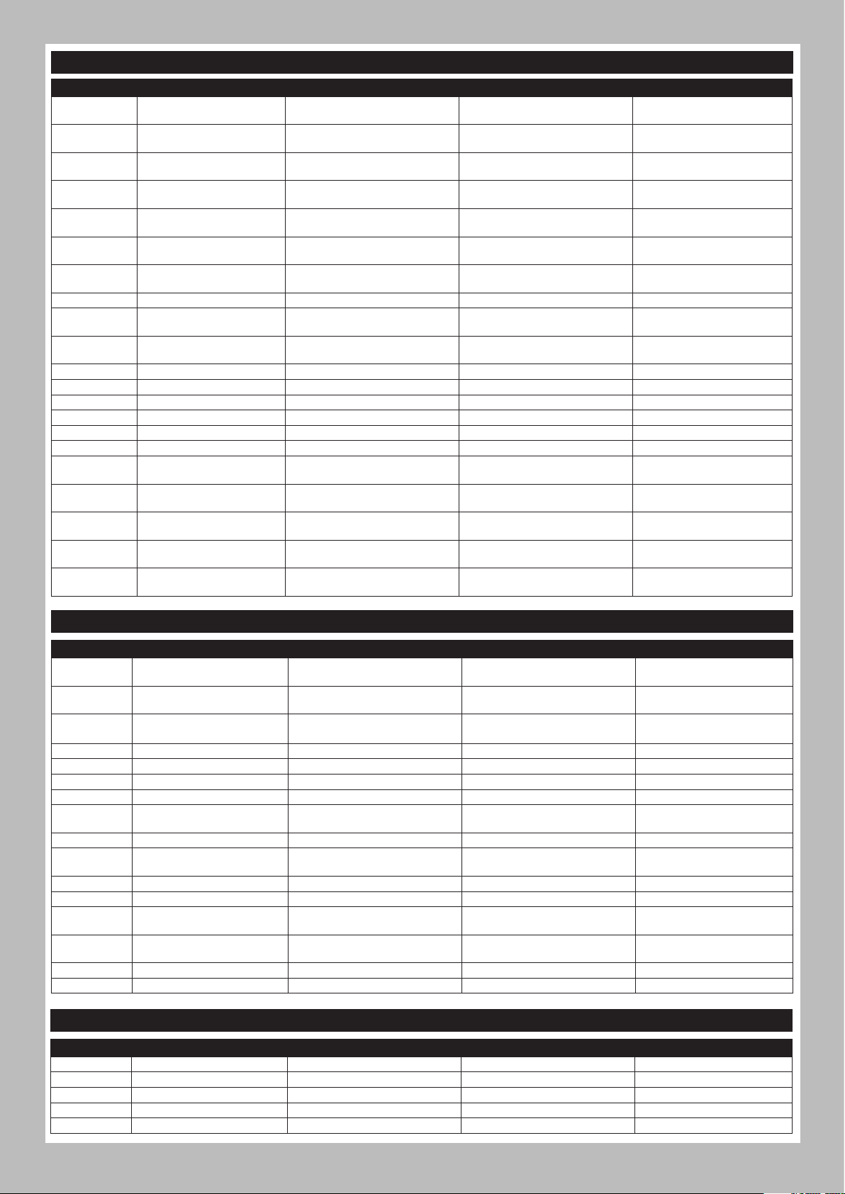
RECOMMENDED PARTS // EMPFOHLENE TEILE// PIÈCES RECOMMANDÉES // PARTI CONSIGLIATE
Part # Description Beschreibung Description Descrizione
DYNB37353
DYNB5025H3
DYNB5035H3
DYNC2030 Prophet Sport Mini 50W Charger Prophet Sport Mini 50W Ladegerät Chargeur Prophet Sport Mini, 50W
DYNC3015
DYNC3016
DYNC3017
DYNS0900 Brushed Crawler Combo 35T Gebürsteter Crawler Combo 35T Brossé Crawler Combo 35T Combo cingolato spazzolato 35T
SPMSS6250
SPMSS6280
SPMX50002S100H3 5000mAh 2S 7.4V Smart 100C; IC3 5000mAh 2S 7,4V Smart 100C; IC3 5000mAh 2S 7,4V Smart 100C; IC3 5000mAh 2S 7,4V Smart 100C; IC3
SPMX50002S30H3 5000mah 2S 7.4V Smart 30C; IC3 5000mah 2S 7,4V Smart 30C; IC3 5000mah 2S 7,4V Smart 30C; IC3 5000mah 2S 7,4V Smart 30C; IC3
SPMX50002S50H3 5000mAh 2S 7.4V Smart 50C; IC3 5000mAh 2S 7,4V Smart 50C; IC3 5000mAh 2S 7,4V Smart 50C; IC3 5000mAh 2S 7,4V Smart 50C; IC3
SPMX50003S100H3
SPMX50003S30H3 5000mah 3S 11.1V Smart 30C; IC3 5000mah 3S 11,1V Smart 30C; IC3 5000mah 3S 11,1V Smart 30C; IC3 5000mah 3S 11,1V Smart 30C; IC3
SPMX50003S50H3 5000mAh 3S 11.1V Smart 50C; IC3 5000mAh 3S 11,1V Smart 50C; IC3 5000mAh 3S 11,1V Smart 50C; IC3 5000mAh 3S 11,1V Smart 50C; IC3
SPMXC1000 Smart S1200 DC Charger, 1x200W
SPMXC1010 Smart S2100 AC Charger, 2X100W
SPMXC1050 Smart S1500 DC Charger, 1x500W
SPMXC1070
SPMXC1080 Smart S1100 AC Charger, 1x100W
11.1V 3700mAh 3S 50CLiPo
96mmEC3
7.4V 5000mAh 2S50C LiPo,
Hardcase: EC3
11.1V 5000mAh 3S 50C
LiPo,Hrdcs:EC3
P1 Mini AC Balance Char/
Dischar
Passport P2 2 Port AC/DC
MultiCharger
Passport P4 AC/DC 4 Port
Multicharger
S6250 U-T / H-S Digital HV WP
Servo
S6280 U-T / H-S Digital HV WP
Servo
5000mAh 3S 11.1V Smart 100C; IC3
Smart S150 AC/DC Charger, 1x50W
11,1V 3700mAh 3S 50CLiPo 96mmEC3 11,1V 3700mAh 3S 50CLiPo 96mmEC3
7,4V 5000mAh 2S 50C LiPo,
Hartschale: EC3
11,1V 5000mAh 3S 50C LiPo,
Hartschale: EC3
Prophet Sport Mini AC Ladegerät Chargeur Prophet Sport Mini, AC
Passport P2 2-Port-AC / DC-MultiLadegerät
Passport P4 4-Port-AC / DC-MultiLadegerät
S6250 U-T / H-S Digitales
wasserdichtes Servo
S6280 U-T / H-S Digitales
wasserdichtes Servo
5000mAh 3S 11,1V Smart 100C; IC3 5000mAh 3S 11,1V Smart 100C; IC3 5000mAh 3S 11,1V Smart 100C; IC3
Smart S1200 Gleichstrom-Ladegerät,
1x200 W
Smart S2100 Gleichstrom-Ladegerät,
2x100 W
Smart S1500 Gleichstrom-Ladegerät,
1x500 W
Smart S150 Gleichstrom-Ladegerät,
1x50 W
Smart S1100 Gleichstrom-Ladegerät,
1x100 W
Li-Po 7,4V 5000mAh 2S 50C, boîtier:
EC3
Li-Po 11,1V 5000mAh 3S 50 C,
boîtier: EC3
Passport P2 Chargeur multiple AC /
DC à 2 ports
Passport P4 Chargeur multiple AC /
DC à 4 ports
S6250 U-T / H-S Servo étanche
numérique
S6280 U-T / H-S Servo étanche
numérique
Chargeur CC Smart S1200, 1x200 W
Chargeur CC Smart S2100, 2x100 W
Chargeur CC Smart S1500, 1x500 W
Chargeur CC Smart S150, 1x50 W
Chargeur CC Smart S1100, 1x100 W
11,1V 3700mAh 3S 50CLiPo
96mmEC3
7,4V 5000mAh 2S 50C LiPo,
hardcase: EC3
11,1 V 5000 mAh 3S 50C LiPo,
hardcase: EC3
Caricabatterie Prophet Sport
Mini, 50W
Caricabatterie Prophet Sport
Mini, AC
Passport P2 Caricatore multiplo
CA / CC a 2 porte
Passport P4 Caricatore multiplo
CA / CC a 4 porte
S6250 U-T / H-S Servo
impermeabile digitale
S6280 U-T / H-S Servo
impermeabile digitale
Caricabatterie Smart S1200 CC,
1x200 W
Caricabatterie Smart S2100 CC,
2x100 W
Caricabatterie Smart S1500 CC,
1x500 W
Caricabatterie Smart S150 CC,
1x50 W
Caricabatterie Smart S1100 CC,
1x100 W
OPTIONAL PARTS // OPTIONALE TEILE // PIÈCES FACULTATIVES // PARTI OPZIONALI
Part # Description Beschreibung Description Descrizione
AXI230025 Uni Body Post Set: SCX10 III Universal-Gehäusestangensatz
AXI231013 Servo Horn, Metal 25T: SCX10III Servohorn, Metall 25T
AXI332001 6-Bolt 27/8 Overdrive Gear Set
AXIC0724 AX30724 Pinion Gear 32p 13t AX30724 Zahnradgetriebe 32p 13t AX30724 Engrenage à pignons 32p 13t AX30724 Pignone 32p 13t
AXIC0725 AX30725 Pinion Gear 32p 14t AX30725 Zahnradgetriebe 32p 14t AX30725 Engrenage à pignons 32p 14t AX30725 Pignone 32p 14t
AXIC0726 AX30726 Pinion Gr 32p 15t 3mm AX30726 Zahnradgetriebe 32p 15t AX30726 Engrenage à pignons 32p 15t AX30726 Pignone 32p 15t
AXIC0727 AX30727 Pinion Gear 32p 16t AX30727 Zahnradgetriebe 32p 16t AX30727 Engrenage à pignons 32p 16t AX30727 Pignone 32p 16t
AXIC1097 AX31097 3-port Led Controller
AXIC1098 AX31098 8 LED Light String White AX31098 8 Weiße LED-Lichtkette
AXIC1152 AX31152 Univ Light Bar Set AX31152 Universal-Leuchtbalkensatz
AXIC7028 AX30728 Pinion Gear 32P 17T AX30728 Zahnradgetriebe 32p 17t AX30728 Engrenage à pignons 32p 17t AX30728 Pignone 32p 17t
DYNH2025 SS Screw St:AxialSCX10 III Edelstahl-Schraubensatz:AxialSCX10 Ensemble de vis en acier inoxydable Set viti inox: AxialSCX10 III
SPMXSE1060 Firma 60ASenseBL Smart Cr ESC
SPMXSEMC08 Firma Sense 1/10 Cr Sys Smart
SPMXSM3001 Firma 2100kv BL Sense Cr Mot FIRMA 2100Kv bürstenloser Motor Moteur sans balais 2100Kv FIRMA Motore BL FIRMA 2100 Kv
SPMXSM3002 Firma 2800kv BL Sense Cr Mot FIRMA 2800Kv bürstenloser Motor Moteur sans balais 2800Kv FIRMA Motore BL FIRMA 2800 Kv
6-Schrauben-27/8-Overdrive-Zahnradsatz
AX31097 LED-Controller mit 3
Anschlüssen
Firma 60A bürstenloser SmartGeschwindigkeitsregler
Firma Sense 1/10 Stromversorgungssystem
Smart
Ensemble de poteaux de carrosserie
universels
Renvoi de commande de servo,
métal 25T
Ensemble d’engrenages d’overdrive
à 6 boulons 27/8
Contrôleur DEL 3 ports AX31097 AX31097 Controller LED 3 porte
Série de lumières DEL blanches AX31098 8
Ensemble de rampe d'éclairage
universel AX31152
Variateur ESC sans balais 60A Smart
Firma
Firma Sense 1/10 système du pouvoir
Smart
Set supporti carrozzeria
universale
Squadretta servo, Metallo 25T
Set di ingranaggi Overdrive 27/8
a 6 bulloni
AX31098 Cordino 8 LED bianco
AX31152 Set barra luminosa univ
Smart ESC Firma 60 A Brushless
Firma Sense 1/10 sistema di
alimentazione Smart
ELECTRONICS // ELECTRONIK // COMPOSANTS ÉLECTRONIQUES // ELETTRONICA
Part # Description Beschreibung Description Descrizione
DYNS1216 35-Turn 540 Brushed Motor 35T Elektromotor Moteur électrique 35T Motore elettrico 35T
SPMRSLT300 SLT3 3CH 2.4Ghz SLT TX Only SLT3 3CH Sender SLT3 3CH Émetteur SLT3 3CH Trasmettitore
SPMS614 Metal Gear Servo Metallgetriebeservo Servo à engrenages métalliques Servo, ingranaggio metallico
SPMSR315 SR315 DSMR 3 CH Receiver SR315 DSMR 3 CH Empfänger Récepteur SR315 DSMR 3 CH Ricevitore SR315 DSMR 3 CH
SPMXSE1040 40A Brushed ESC 40 Amp Geschwindigkeitsregler ESC 40 Amp ESC 40 Amp
57
Page 22

NOTES // ANMERKUNGEN // REMARQUES // NOTA
58
Page 23

NOTES // ANMERKUNGEN // REMARQUES // NOTA
59
Page 24

facebook.com/axialinc | instagram.com/axialracing | twitter.com/axialrc
youtube.com/axialvideos | flickr.com/axialrc
©2022 Horizon Hobby, LLC.
Axial, the Axial logo, SCX-10, Proline, the Proline logo, DSM, DSMR, SLT3, IC3, EC3, Passport, and the Horizon Hobby logo
are trademarks or registered trademarks of Horizon Hobby, LLC.
General Motors Trademarks are used under license to Horizon Hobby, LLC.
The Spektrum trademark is used with permission of Bachmann Industries, Inc. All other trademarks, service marks and logos are property of their respective owners.
US 9,930,567. US 10,419,970. US 10,849,013. Other patents pending.
Completed 06/22 AXI03029 236420
 Loading...