

Page 1
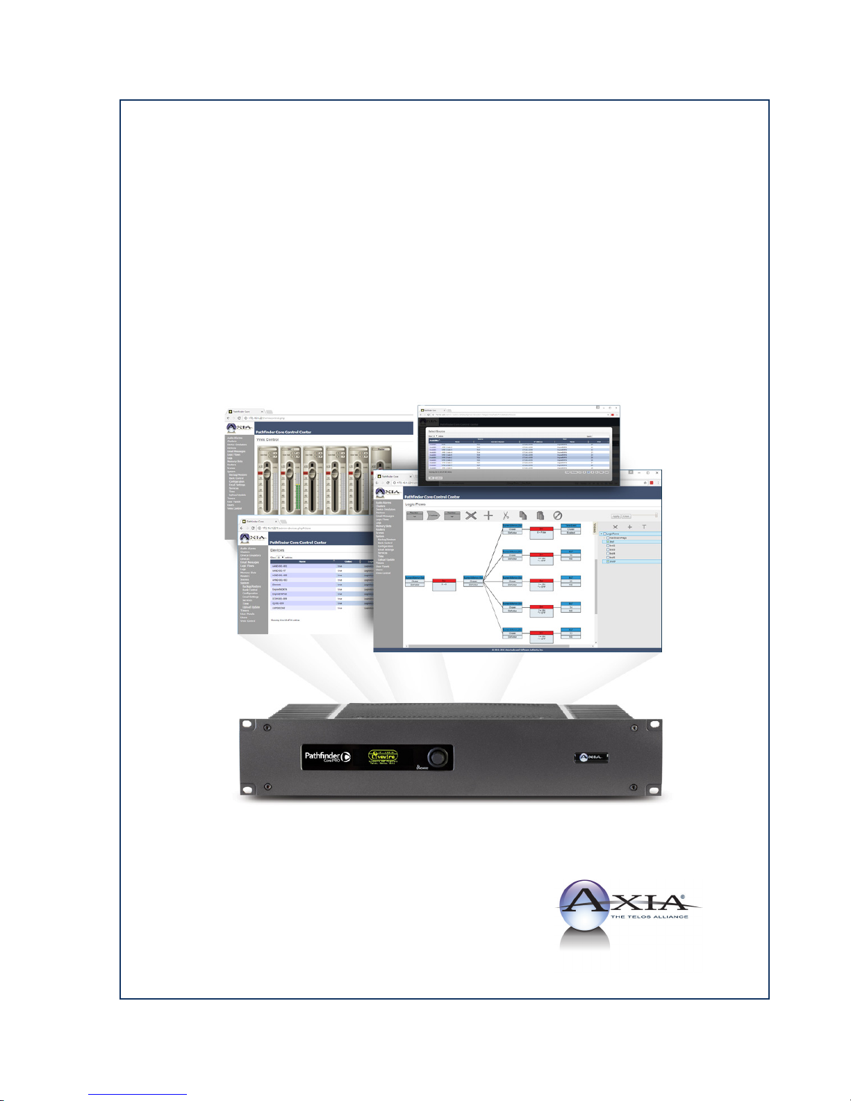
Pathfinder Core PRO
Installation & User’s Guide
Manual Rev 1.2 - Oc tober 2017
For P/N 2001-00296
Page 2

Notices and Cautions
CAUTION:
The installation and service instructions in this manual are for use by qualied personnel only. To avoid electric
shock, do not perform any servicing other than that contained in the operating instructions unless you are qualied to
do so. Refer all servicing to qualied personnel.
This instrument has an autoranging line voltage input. Ensure the power voltage is within the specied range of
100-240v. The ~ symbol, if used, indicates an alternating current supply.
This symbol, wherever it appears, alerts you to the presence of uninsulated, dangerous voltage
inside the enclosure – voltage which may be sufcient to constitute a risk of shock.
This symbol, wherever it appears, alerts you to important operating and maintenance instructions.
Read the manual.
CAUTION: DOUBLE POLE/NEUTRAL FUSING
The instrument power supply incorporates an internal fuse. Hazardous voltages may still be present on some of the
primary parts even when the fuse has blown. If fuse replacement is required, replace fuse only with same type and
value for continued protection against re.
WARNING:
The product’s power cord is the primary disconnect device. The socket outlet should be located near the device
and easily accessible. The unit should not be located such that access to the power cord is impaired. If the unit is
incorporated into an equipment rack, an easily accessible safety disconnect device should be included in the rack
design.
To reduce the risk of electrical shock, do not expose this product to rain or moisture. This unit is for indoor use only.
This equipment requires the free ow of air for adequate cooling. Do not block the ventilation openings in the top
and sides of the unit. Failure to allow proper ventilation could damage the unit or create a re hazard. Do not place
the units on a carpet, bedding, or other materials that could interfere with any panel ventilation openings.
If the equipment is used in a manner not specied by the manufacturer, the protection provided by the equipment
may be impaired.
Notices and Cautions • ii
© 2017 Telos Alliance - Rev 1.2
Page 3
WARNUNG:
Die Installations-und Serviceanleitung in diesem Handbuch ist für die Benutzung durch qualiziertes Fachpersonal.
Um Stromschläge zu vermeiden führen Sie keine andere Wartung durch als in dieser Betriebsanleitung aufgeführt,
es sei denn Sie sind dafür qualiziert. Überlassen Sie alle Reparaturarbeiten qualiziertem Fachpersonal.
Dieses Gerät hat eine automatische Bereichseinstellung der Netzspannung.
Stellen sie sicher, dass die verwendete Netzspannung im Bereich von 100-240V liegt.
Das Symbol ~, falls verwendet, bezeichnet eine Wechselstromversorgung.
Dieses Symbol, wo immer es auftaucht, macht Sie auf nicht isolierte, gefährliche elektrische
Spannung (ausreichend um einen Stromschlag hervorzurufen) innerhalb des Gehäuses aufmerksam.
Spannungen.
Dieses Symbol, wo immer es auftaucht, weist Sie auf wichtige Bedienungs-und Wartungsanleitung
hin. Lesen Sie die Bedienungsanleitung.
ACHTUNG: ZWEIPOLIGE ABSICHERUNG / NULLEITER ABSICHERUNG
Das Netzteil des Gerätes hat eine interne Sicherung eingebaut. Auch wenn die Sicherung durchgebrannt ist, können
auf einigen primären Bauteilen noch gefährliche Spannungen vorhanden sein. Wenn ein Austausch der Sicherung
erforderlich ist, ersetzen Sie die Sicherung nur mit gleicher Art und Wert für den kontinuierlichen Schutz gegen
Feuer.
WARNUNG:
Das Gerätenetzkabel ist die Haupttrennvorrichtung. Die Steckdose sollte sich in der Nähe des Gerätes benden und
leicht zugänglich sein. Das Gerät sollte nicht so angeordnet sein, dass der Zugang zum Netzkabel beeinträchtigt
ist. Wird das Gerät in ein Rack eingebaut, sollte eine leicht zugängliche Sicherheitstrennvorrichtung in den Rack-
Aufbau mit einbezogen werden.
Um die Gefahr von Stromschlägen zu verringern, darf dieses Produkt nicht Regen oder Feuchtigkeit ausgesetzt
werden. Dieses Gerät ist nur für die Benützung im Innenbereich. Dieses Gerät erfordert freie Luftzirkulation für
eine ausreichende Kühlung. Blockieren sie nicht die Lüftungsschlitze auf der Geräteoberseite und den Seiten des
Gerätes. Unzureichende Belüftung kann das Gerät beschädigen oder Brandgefahr verursachen. Platzieren Sie
das Gerät nicht auf einem Teppich, Poster oder andere Materialien welche die Lüftungsöffnungen beeinträchtigen
könnten.
Wird das Gerät anders als in der, vom Hersteller angegebenen Weise verwendet, kann der, durch das Gerät gegebene
Schutz beeinträchtigt werden.
Notices and Cautions • iii
© 2017 Telos Alliance - Rev 1.2
Page 4

USA CLASS A COMPUTING DEVICE INFORMATION TO USER. WARNING:
This equipment generates, uses, and can radiate radio-frequency energy. If it is not installed and used as directed by
this manual, it may cause interference to radio communication. This equipment complies with the limits for a class
a computing device, as specied by fcc rules, part 15, subpart j, which are designed to provide reasonable protection
against such interference when this type of equipment is operated in a commercial environment. Operation of this
equipment in a residential area is likely to cause interference. If it does, the user will be required to eliminate the
interference at the user’s expense. Note: objectionable interference to tv or radio reception can occur if other devices
are connected to this device without the use of shielded interconnect cables. Fcc rules require the use of shielded
cables.
CANADA WARNING:
“This digital apparatus does not exceed the class a limits for radio noise emissions set out in the radio interference
regulations of the Canadian department of communications.”
“Le présent appareil numérique n’émet pas de bruits radioélectriques dépassant les limites applicables aux appareils
numériques (de class a) prescrites dans le règlement sur le brouillage radioélectrique édicté par le ministère des
communications du Canada.”
CE CONFORMANCE INFORMATION:
This device complies with the requirements of the EEC council directives:
• 93/68/EEC (CE MARKING)
• 73/23/EEC (SAFETY – LOW VOLTAGE DIRECTIVE)
• 89/336/EEC (ELECTROMAGNETIC COMPATIBILITY)
Conformity is declared to those standards: EN50081-1, EN50082-1.
Notices and Cautions • iv
© 2017 Telos Alliance - Rev 1.2
Page 5

Pathfinder Core PRO Manual
© 2014-2017 TLS Corp. and Software Authority, Inc. Published by Axia Audio/TLS Corp. All rights reserved.
TRADEMARKS
Axia Audio and the Axia logo are trademarks of TLS Corp. All other trademarks are the property of their respective
holders.
NOTICE
All versions, claims of compatibility, trademarks, etc. of hardware and software products not made by Axia Audio
which are mentioned in this manual or accompanying material are informational only. Axia makes no endorsement
of any particular product for any purpose, nor claims any responsibility for operation or accuracy. We reserve the
right to make improvements or changes in the products described in this manual which may affect the product
specications, or to revise the manual without notice.
WARRANTY
Telos Alliance Radio Division has an industry-leading ve-year warranty.
As a company, we are commited to our products and the pursuit of providing better quality to our
customers. Find the Warranty online at www.telosalliance.com/warranty.
UPDATES
The operation of Pathnder Core PRO is determined largely by software. We routinely release new versions to
add features and x bugs. Check the Axia Audio web site for the latest. We encourage you to sign-up for the email
notication service offered on the site.
Notices and Cautions • v
FEEDBACK
We welcome feedback on any aspect of Pathnder Core PRO, or this manual. In the past, many good ideas from
users have made their way into software revisions or new products. Please contact us with your comments.
SERVICE
You must contact Axia before returning any equipment for factory service. We will need your unit’s serial number,
located on the back of the unit. Axia will issue a return authorization number, which must be written on the exterior
of your shipping container. Please do not include cables or accessories unless specically requested by the Technical
Support Engineer. Be sure to adequately insure your shipment for its replacement value. Packages without proper
authorization may be refused. US customers, please contact Axia Technical Support at +1-216-622-0247. All other
customers should contact local representative to make arrangements for service.
© 2017 Telos Alliance - Rev 1.2
Page 6

We Support You...
BY PHONE / FAX:
• You may reach our 24/7 Support team anytime around the clock by calling +1-216-622-0247.
• For billing questions or other non-emergency technical questions, call +1-216-241-7225 between 9:30 am
to 6:00 PM, USA Eastern time, Monday through Friday.
• Our Fax number is +1-216-241-4103.
BY E-MAIL:
• Technical support is available at [email protected].
• All other questions, please email [email protected].
VIA WORLD WIDE WEB:
The Axia Audio web site has a variety of information which may be useful for product selection and support. The url
is telosalliance.com.
REGISTER YOUR PRODUCT
Did you know that all Telos Alliance products come with a 5-Year Warranty? Take a moment to activate your
coverage online at http://telosalliance.com/product-registration/ .
TELOS ALLIANCE
1241 Superior Avenue E.
Cleveland, OH., 44114 USA
+1-216-241-7225 (phone)
+1-216-241-4103 (fax)
+1-216-622-0247 (24/7 technical support)
We Support You • vi
© 2017 Telos Alliance - Rev 1.2
Page 7

Table of Contents
We Support You . . . . . . . . . . . . . . . . . . . . . vi
War of the Waves . . . . . . . . . . . . . . . . . . . . .ix
Chapter 1 Quickstart. . . . . . . . . . . . . . . . . . .1
Chapter 2 Overview . . . . . . . . . . . . . . . . . . . 4
Web Browsers . . . . . . . . . . . . . . . . . . . . . 4
Navigation Bar. . . . . . . . . . . . . . . . . . . . . 4
Lists: Searching and Sorting. . . . . . . . . . . . . . 5
Event System Catch 22 . . . . . . . . . . . . . . . .6
Chapter 3 System . . . . . . . . . . . . . . . . . . . . .7
Status . . . . . . . . . . . . . . . . . . . . . . . . .7
Version . . . . . . . . . . . . . . . . . . . . . . . 7
Licensing . . . . . . . . . . . . . . . . . . . . . . 7
System Status . . . . . . . . . . . . . . . . . . . .7
Downloads . . . . . . . . . . . . . . . . . . . . . 8
Conguration . . . . . . . . . . . . . . . . . . . . .8
Livewire Endpoint Discovery. . . . . . . . . . . .8
Restart System . . . . . . . . . . . . . . . . . . . 9
Factory Default System. . . . . . . . . . . . . . .9
Hostname . . . . . . . . . . . . . . . . . . . . . .9
Advanced Options . . . . . . . . . . . . . . . . . 9
Logout . . . . . . . . . . . . . . . . . . . . . . . 9
Network Conguration . . . . . . . . . . . . . . .9
Licenses . . . . . . . . . . . . . . . . . . . . . . . . 11
Backup/Restore . . . . . . . . . . . . . . . . . . . .11
Upload Update. . . . . . . . . . . . . . . . . . . . . 13
Bank Control . . . . . . . . . . . . . . . . . . . . .15
Services . . . . . . . . . . . . . . . . . . . . . . . .16
Time . . . . . . . . . . . . . . . . . . . . . . . . . . 17
Email Settings . . . . . . . . . . . . . . . . . . . . . 18
Virtual Routers . . . . . . . . . . . . . . . . . . . 25
Chapter 6 Logic Flows . . . . . . . . . . . . . . . . . . 29
Views . . . . . . . . . . . . . . . . . . . . . . . . .30
Toolbar. . . . . . . . . . . . . . . . . . . . . . . . . 31
First Flow . . . . . . . . . . . . . . . . . . . . . . .32
Dynamic Data . . . . . . . . . . . . . . . . . . . . . 37
Combiners and the second ow . . . . . . . . . . . . 38
Going Crazy . . . . . . . . . . . . . . . . . . . . . . 41
Extending Flows. . . . . . . . . . . . . . . . . . . . 41
Cut, Copy, and Paste. . . . . . . . . . . . . . . . . . 42
Flow Titling . . . . . . . . . . . . . . . . . . . . . . 42
Disabling/Enabling . . . . . . . . . . . . . . . . . .43
Cluster Disabling . . . . . . . . . . . . . . . . . . .43
Object Translators . . . . . . . . . . . . . . . . . . . 44
Latching . . . . . . . . . . . . . . . . . . . . . . . . 46
Property List Types: Simple versus API. . . . . . . . 48
Simple Tree Commonly Used Properties . . . . . . . 49
Flows, Flows, and More Flows . . . . . . . . . . . . 52
Chapter 7 Memory Slots . . . . . . . . . . . . . . . . . 53
Chapter 8 Timers . . . . . . . . . . . . . . . . . . . . .55
Chapter 9 Scenes . . . . . . . . . . . . . . . . . . . . . 59
Chapter 10 Audio Alarms . . . . . . . . . . . . . . . . 61
Chapter 11 User Panels. . . . . . . . . . . . . . . . . .64
Chapter 12 E-mail Messages. . . . . . . . . . . . . . .65
Chapter 13 Device Emulators . . . . . . . . . . . . . . 68
Generic . . . . . . . . . . . . . . . . . . . . . . . .69
Escape Characters . . . . . . . . . . . . . . . . . 70
Probel General Router and General Switcher . . . . . 70
Chapter 4 Devices. . . . . . . . . . . . . . . . . . . . .19
Chapter 5 Routers . . . . . . . . . . . . . . . . . . . . 20
Points . . . . . . . . . . . . . . . . . . . . . . . . .21
Routes . . . . . . . . . . . . . . . . . . . . . . . . . 22
Router Types. . . . . . . . . . . . . . . . . . . . . . 23
Axia Audio Router . . . . . . . . . . . . . . . . . 23
Axia GPIO Router . . . . . . . . . . . . . . . . . 25
Table of Contents • vii
Chapter 14 Logs . . . . . . . . . . . . . . . . . . . . . 71
Chapter 15Vmix Control. . . . . . . . . . . . . . . . .75
Vmixer Shortcuts . . . . . . . . . . . . . . . . . . .77
Chapter 16 Users . . . . . . . . . . . . . . . . . . . . . 78
© 2017 Telos Alliance - Rev 1.2
Page 8

Clock Control Properties . . . . . . . . . . . . . .113
Chapter 17 Clusters . . . . . . . . . . . . . . . . . . . 81
Creating a Cluster . . . . . . . . . . . . . . . . . . . 81
Joining a Cluster. . . . . . . . . . . . . . . . . . . . 82
Manual Sync. . . . . . . . . . . . . . . . . . . . . . 83
Leaving a Cluster . . . . . . . . . . . . . . . . . . .83
Events and Timers . . . . . . . . . . . . . . . . . . . 84
Clustering and SapV2 . . . . . . . . . . . . . . . . . 84
Chapter 18 PathnderPC_Core Client . . . . . . . . . 85
PathnderPC_Core Installation . . . . . . . . . . . . 85
PathnderPC_Core Main Application. . . . . . . . . 86
Select List. . . . . . . . . . . . . . . . . . . . . .90
Metering . . . . . . . . . . . . . . . . . . . . . . 91
Scenes . . . . . . . . . . . . . . . . . . . . . . . 92
Virtual Routers . . . . . . . . . . . . . . . . . . . 93
Search Functions . . . . . . . . . . . . . . . . . .97
Routers Menu. . . . . . . . . . . . . . . . . . . .99
Scenes Menu . . . . . . . . . . . . . . . . . . . . 99
User Panels Menu . . . . . . . . . . . . . . . . . 100
Meter Bridge Menu. . . . . . . . . . . . . . . . .100
Toolbars Menu . . . . . . . . . . . . . . . . . . . 100
View Menu . . . . . . . . . . . . . . . . . . . . . 100
Window Menu . . . . . . . . . . . . . . . . . . . 100
Help Menu . . . . . . . . . . . . . . . . . . . . . 101
PathnderPC_Core Client Registry Settings . . . . .101
Chapter 19 Panel Designer. . . . . . . . . . . . . . . .102
Connecting Panel Designer to Pathnder Core PRO .103
Creating a Panel . . . . . . . . . . . . . . . . . . . . 103
Arranging controls on the form . . . . . . . . . . 104
Setting Control Properties . . . . . . . . . . . . . 104
Property Descriptions . . . . . . . . . . . . . . . . . 109
Panel Properties . . . . . . . . . . . . . . . . . . 109
Label Control Properties . . . . . . . . . . . . . .109
Button Control Properties . . . . . . . . . . . . . 110
Meter Control Properties. . . . . . . . . . . . . .112
MeterFader Control Properties . . . . . . . . . . 113
WebBrowser Control Properties . . . . . . . . . . 113
Chapter 20 PathnderPC_Core Mini . . . . . . . . . .115
Appendix A: SapV2. . . . . . . . . . . . . . . . . . . .117
Message Overview . . . . . . . . . . . . . . . . . .118
Discovery . . . . . . . . . . . . . . . . . . . . . . .119
$MAX_DEPTH System item examples . . . . . . .120
Subscription Examples . . . . . . . . . . . . . . . .123
Init Examples . . . . . . . . . . . . . . . . . . . . .124
Delete Examples. . . . . . . . . . . . . . . . . . . . 124
Request for syntax . . . . . . . . . . . . . . . . . . . 124
Routing Paths . . . . . . . . . . . . . . . . . . . . .125
Operators . . . . . . . . . . . . . . . . . . . . . . .125
Untargetted Operators . . . . . . . . . . . . . . . . . 126
Operator Examples . . . . . . . . . . . . . . . . . .127
LOGIN . . . . . . . . . . . . . . . . . . . . . . . 127
GET. . . . . . . . . . . . . . . . . . . . . . . . .127
SET . . . . . . . . . . . . . . . . . . . . . . . . . 127
INDI . . . . . . . . . . . . . . . . . . . . . . . . 128
SUB . . . . . . . . . . . . . . . . . . . . . . . . .128
INIT. . . . . . . . . . . . . . . . . . . . . . . . .128
DEL. . . . . . . . . . . . . . . . . . . . . . . . .128
NOP . . . . . . . . . . . . . . . . . . . . . . . . 129
SYNC . . . . . . . . . . . . . . . . . . . . . . . . 129
RFS and SFR . . . . . . . . . . . . . . . . . . . . 129
Object Path . . . . . . . . . . . . . . . . . . . . . .132
Properties . . . . . . . . . . . . . . . . . . . . . . .132
Hidden Properties . . . . . . . . . . . . . . . . . 132
Property Values . . . . . . . . . . . . . . . . . . .132
System Items . . . . . . . . . . . . . . . . . . . . .133
Additional System Item Notes . . . . . . . . . . . 134
Warranty: Telos Alliance Limited Warranty . . . . . . 135
Table of Contents • viii
© 2017 Telos Alliance - Rev 1.2
Page 9

War of the Waves
Dear Valued Customer,
It’s with great pride and a tip of the hat to an incredible team that I congratulate you on your new Telos Alliance
product. Everything we do here at the radio division of the Telos Alliance is with one end goal in mind: To help
broadcasters declare victory in extremely competitive environments. By purchasing this product from us, in essence,
you have declared war on your competition.
After all, the majority of Telos Alliance employees were broadcasters themselves once, and the products we’ve
developed over the years have been designed as solutions to specic issues faced on the front lines of our industry.
We’re right there in the trenches with you and have the weapons you need in your arsenal.
Telos Systems is a catalyst to out-of-this-world sound, with the most powerful and popular broadcast telephone
systems in the industry; IP/ISDN codecs and transceivers; plus processing/encoding for streaming audio. We built an
industry on the back of these amazing telephony systems, and they are still going strong.
While we at the Telos Alliance never forget our roots, we are also blazing trails in terms of new technologies like
stream-encoding and AoIP, so that all types of broadcasters can excel in this ever-evolving digital world.
Omnia Audio not only lets you stand out on the dial with your unique signature sound via legendary audio
processors, audio codecs, and microphone processing, it lets you give your listeners a better streaming experience
across devices with innovative stream encoding/processing software and hardware.
A Note From Frank Foti • ix
Axia Audio is a driving force behind the AES67 AoIP standard, and its networked AoIP radio consoles, audio
interfaces, networked intercom, and software products continue to move AoIP adoption forward and help
broadcasters streamline operations with cohesive, smart, and feature-rich AoIP ecosystems.
Last, but certainly not least, 25-Seven has traditionally been known for its audio delays, but its Voltair watermark
monitor/processor has made a name for itself more recently as the disruptive product that helped broadcasters take
back their ratings and harness the true power of their listening audiences.
You work so hard on your programming day-in and day-out, it deserves technology that will optimize sound and
performance at every point in the airchain and online. Armed with Telos products, you have what you need to set
your competition squarely in your crosshairs.
With that, I’ll leave you to prep your armaments. I hope that you will enjoy your Telos Alliance products for many
years to come!
Sincerely,
Frank Foti
CEO, The Telos Alliance
© 2017 Telos Alliance - Rev 1.2
Page 10
Chapter 1
Quickstart
Congratulations on your purchase of the Pathnder Core PRO. We know that you’re anxious to get started, so this
section will take you from ‘out of the box’ to ‘up and running as quickly as possible.
We make a few basic assumptions:
• That you have some knowledge of network basics and network terminology,
• That you are familiar with other Axia Livewire products,
• That you have a correctly congured network switch
Once you’re all set up, please peruse the remainder of this manual to gain an in-depth knowledge of Core PRO’s
more advanced options.
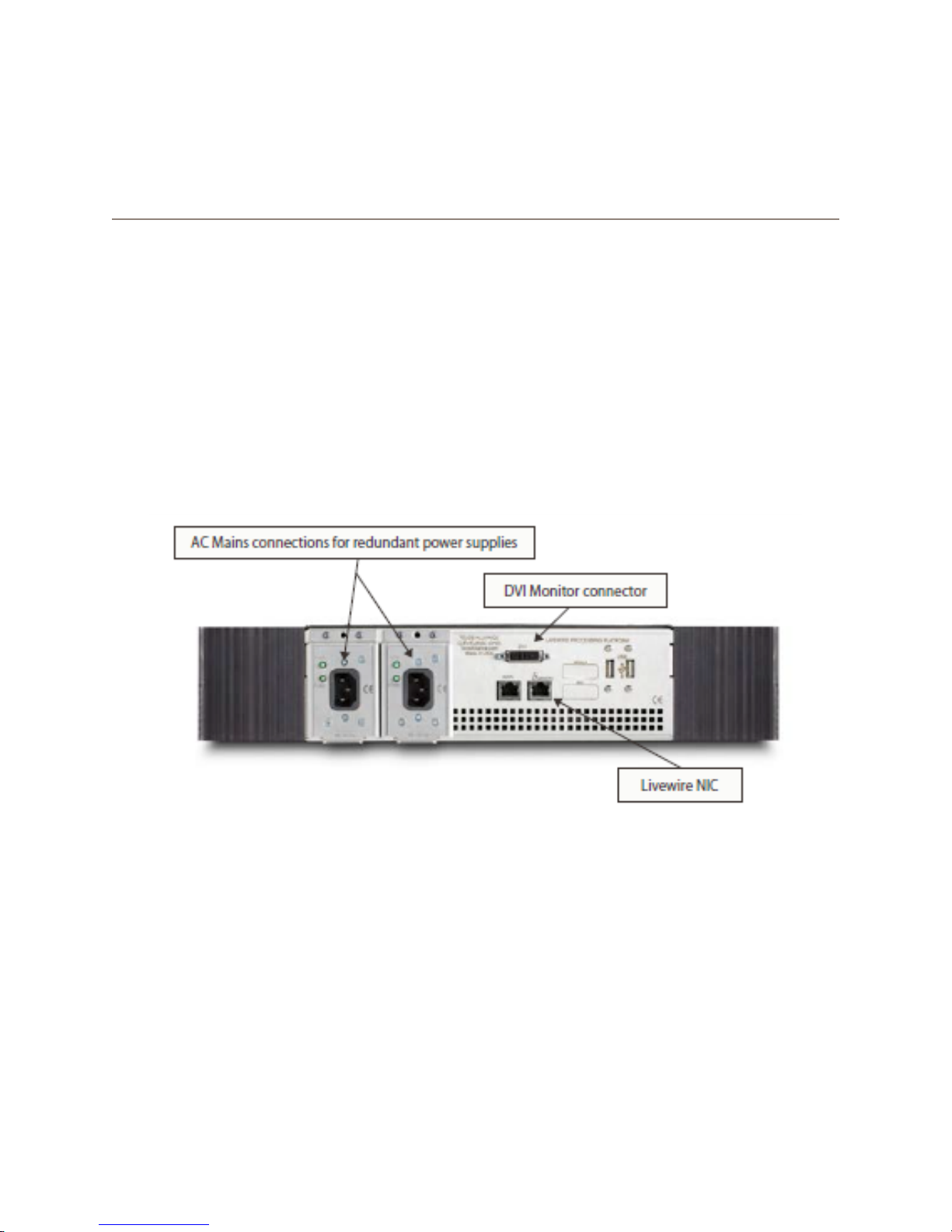
The DVI monitor connector on the back of the Pathnder Core PRO studio engine is not necessary for normal
operations. All conguration can be completed through the front panel and the online web pages. Support may
ask you to connect a monitor to this port in the course of a support session but otherwise, you may leave this port
disconnected.
Connect the RJ-45 port marked with the Livewire logo to a port on your AoIP network’s local switch using a CAT-6
Ethernet cable.
Connect the RJ-45 port marked with the WAN caption to your ofce network if you wish to run Pathnder Client
applications in the business environment so that your users may control Axia equipment without providing direct
access to the Axia network.
1: Quickstart • 1
© 2017 Telos Alliance - Rev 1.2
Page 11
Using the IEC cables supplied, connect the Pathnder Core PRO’s power supply input to AC mains.
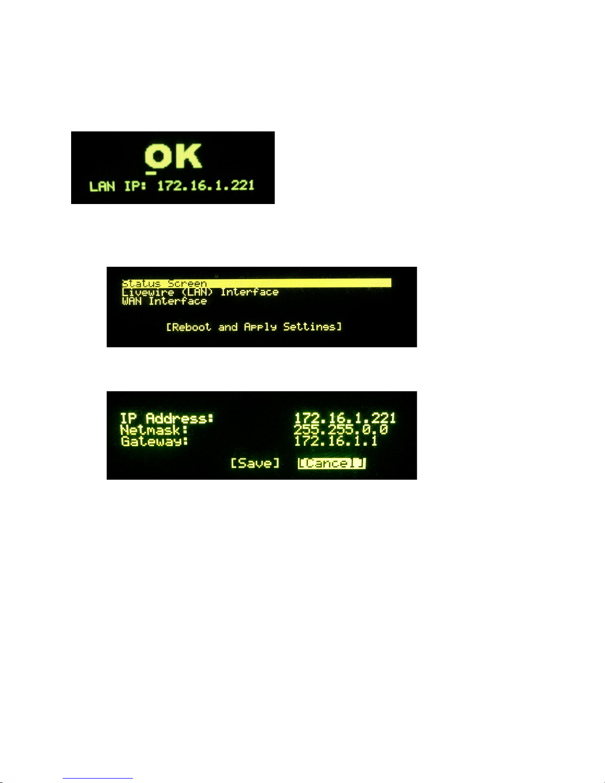
Once Pathnder Core PRO has booted, its display will show the OK logo along with the default IP address shipped
from the factory.
You will need to enter the IP address, netmask, and gateway you wish to use for the system. To do this:
1. Tap the rotary encoder on the front panel, once. A menu view will appear.
2. Rotate the encoder to highlight “Livewire (Lan) Interface”, and tap the encoder again to select it. A new
menu will appear.
3. Tap the encoder to enter the “IP Address” setting.
4. Rotate the encoder to move the onscreen cursor. A tap on any of the cursor positions allows you to edit its
numeric value; rotate the encoder to increment or decrement the value and tap to accept the change. Repeat
this until the IP address you desire is entered. When you scroll beyond the last digit of the IP address the
system will return to highlighting the main menu items.
5. Rotate the encoder to highlight “Netmask”, and tap the encoder to select it. Rotate the encoder to scroll
through the possible Netmask settings. Tap the encoder again to return to the main menu items.
6. Rotate the encoder to highlight “Gateway”, and tap the encoder to begin changing the gateway settings.
Repeat the steps you used to set the IP address to set the Gateway address.
7. Once the gateway has been set, rotate the encoder again to highlight Save, and tap the encoder to save the
“Livewire (LAN) Interface settings.
1: Quickstart • 2
8. Rotate the encoder to “WAN Interface” and repeat the procedures above to set the WAN IP address.
© 2017 Telos Alliance - Rev 1.2
Page 12
Important Note: Core PRO only allows a single gateway and will use whichever gateway address is most
recently set on L AN or WAN. It is recommended to use the same gateway for both. Having multiple
gateways could cause the system to arbitrarily select which one to use with unpredictable results so this
is disallowed.
Once the WAN IP address settings have been assigned, rotate the encoder to select Reboot and Apply Settings.
The next step requires a Web browser on a PC connected to either the ofce or Livewire network. If your computer
is connected to the ofce network, then open your browser and enter the IP you assigned to the WAN port into the
URL bar. If your PC is connected to the Axia network, then open your browser and enter the IP you assigned to the
livewire port into the URL bar. An authentication window will appear. Enter the following values:
• Username = Admin
• Password = Admin
Select “OK” and your Pathnder Core PRO control panel will be loaded.
From the links in the left hand navigation bar select Conguration under the System heading. A new page will load.
Next to “Livewire Endpoint Discovery”, click on the Start button.
Now would be a good time to grab a cup of coffee while the system evaluates the network, discovers devices, and
builds your primary audio and GPIO routers.
As long as the Discovery is running, the system will continue to look for new devices. There is no complete
message, but if you click on the Devices link in the navigation bar, you should start to see devices being populated
into that page.
Congratulations! Your Pathnder Core PRO is now congured and ready to start controlling your broadcasting world.
1: Quickstart • 3
© 2017 Telos Alliance - Rev 1.2
Page 13

Chapter 2
Overview
Pathnder Core PRO is designed to offer you the ultimate in control of your Axia network. It is a toolbox that
allows you to fashion your own custom workows for your users. At its foundation it provides router control. By
communicating with all of the Axia devices on your network, it brings the sources and destinations together into a
common user interface that can then be used to make route changes anywhere in the system.
But it also offers control over console parameters, metering, audio levels, and many more parameters that an Axia
system provides. Plus, it allows you to design your own user interfaces to display this information and allow your
users to have the precise degree of control and information over the system you wish them to have. Building on the
highly successful PathnderPro product line, Pathnder Core PRO strives to make the information about your Axia
system more dynamic, visible, and accessible than ever before.
Web Browsers
Pathnder Core PRO uses a number of modern web browser tools to bring a rich and dynamic user experience to
the product, including web sockets and HTML5. This comes at the expense of being unable to support older web
browsers. For example, web sockets are only supported in Internet Explorer 10 and later. Most of our development
work has been done using Google Chrome. That browser should provide the most consistent and best user
experience.
If data does not seem to display properly, or if data is missing in whatever browser you are using, it is sometimes
useful to try refreshing the web page using the refresh button. Many browsers also have a key combination that will
force a refresh from the serving device rather than perhaps relying on cached data. If you nd things that do not
work or behave properly in a specic browser or are not updating the data properly, please feel free to le a report
with Axia support so that we can investigate the issue. We are always striving to improve the user experience across
all browsers.
Navigation Bar
All of the links necessary to congure, control, and monitor your Pathnder Core PRO system are on the left hand
side of the Pathnder Core PRO web pages. This will be referred to throughout the manual as the navigation bar.
While the links on this bar are presented alphabetically for ease of use, this manual will skip from link to link as we
go through a logical progression of using the system.
2: Overview • 4
© 2017 Telos Alliance - Rev 1.2
Page 14
Lists: Searching and Sorting
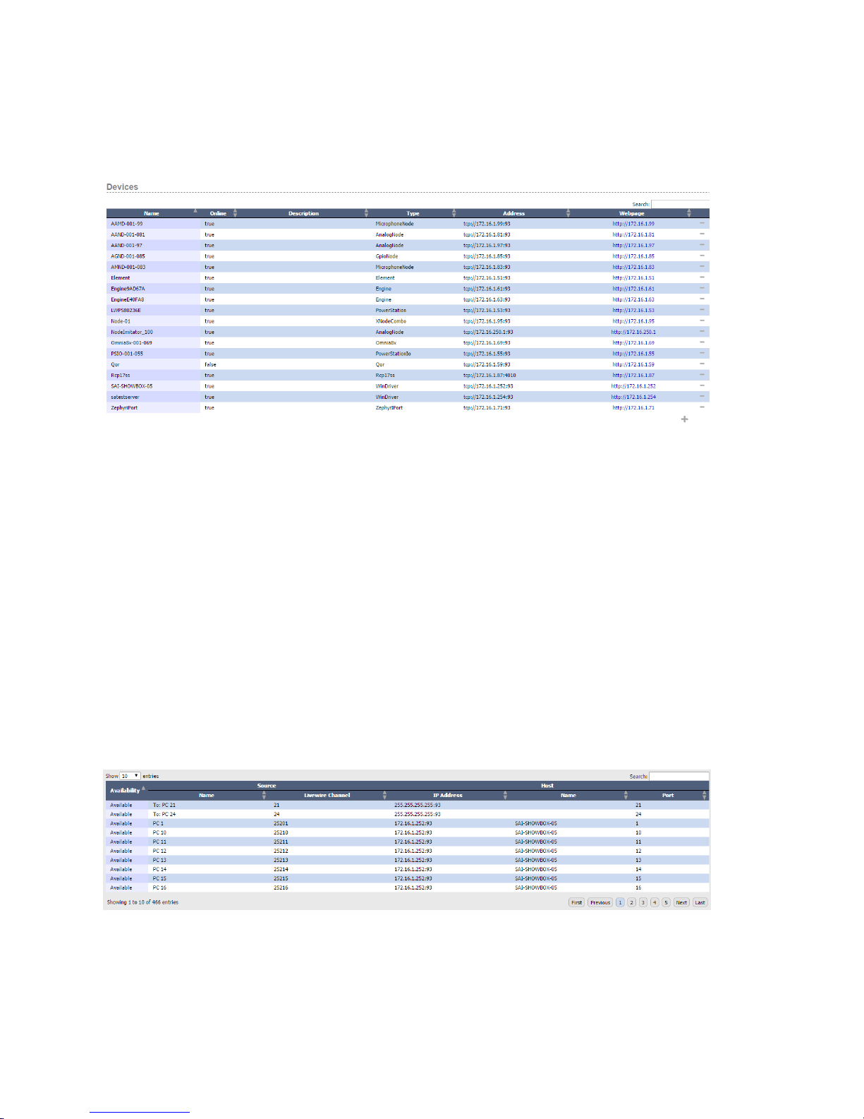
Many of the conguration pages in Pathnder Core PRO need to present lists of data. For example:
There are a few conventions that apply whenever you see a list like this in Pathnder Core PRO. The rst is the
Search box in the right corner. Typing in the search box will dynamically lter the list. These lters are also often
stored by the browser so if you return to a page and do not see data in the list that you are expecting to see, check
the search eld to see if you have a lter on the list.
Next notice that each column header has arrows next to the header names. Clicking on the header will sort the list
according to the data in that column. The column that only has the single arrow represents the current sort column.
Clicking on that column a second time will ip the arrow to the other direction and ip the sort from incrementing to
decrementing and back again.
Many of the lists will have the hyphen sign in the last column of the list. This indicates that the particular item in
the list may be removed from the system by clicking that icon. This is the delete icon. Many of the lists will also
have a plus sign at the bottom of the list. This sign indicates that items may be added to the list. Clicking the plus
sign will usually open another dialog box with specics for how to add a new item into the system.
As lists expand beyond what will t on a page there may also be navigation buttons. For example:
2: Overview • 5
© 2017 Telos Alliance - Rev 1.2
Page 15

In this example, there is a drop down in the upper left corner that allows you to dene how many entries you wish
to see on a page and a set of buttons in the bottom right corner that allows you to navigate through the pages of the
list. The bottom left corner may also display the total quantity of items which are being shown. It is important to
understand that these navigation tools are subject to the search eld. In the case above if we were to enter PC 14
into the search eld, then we may get only a single entry in the list and the page buttons would only show a single page.
Event System Catch 22
Pathnder Core PRO includes an event system called Logic Flows. However, since Logic Flows can reach into almost
every part of the system, it presents a bit of a Catch 22 when it comes to introducing certain subjects in a manual.
There are certain subjects such as Memory slots that are primarily useful in the context of Logic Flows. So you
have to understand Logic Flows in order to make the best use of memory slots. However, the examples and
discussions within the Logic Flows section of the manual also will refer to memory slots in order to present some of
its examples. Wherever possible, we attempt to note this and refer to the relevant sections of this manual. However,
as a reader, be prepared to skip around if necessary. If the manual is read from front to back, there may be points
where we refer to subjects covered in a later section.
2: Overview • 6
© 2017 Telos Alliance - Rev 1.2
Page 16
Chapter 3
System
Status
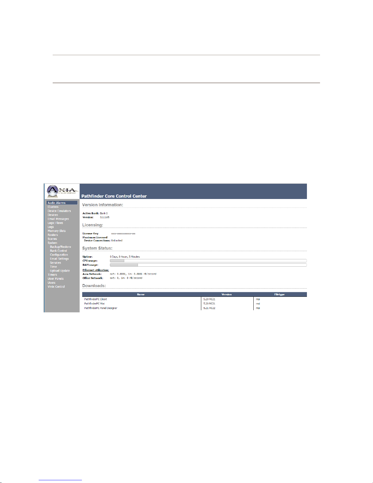
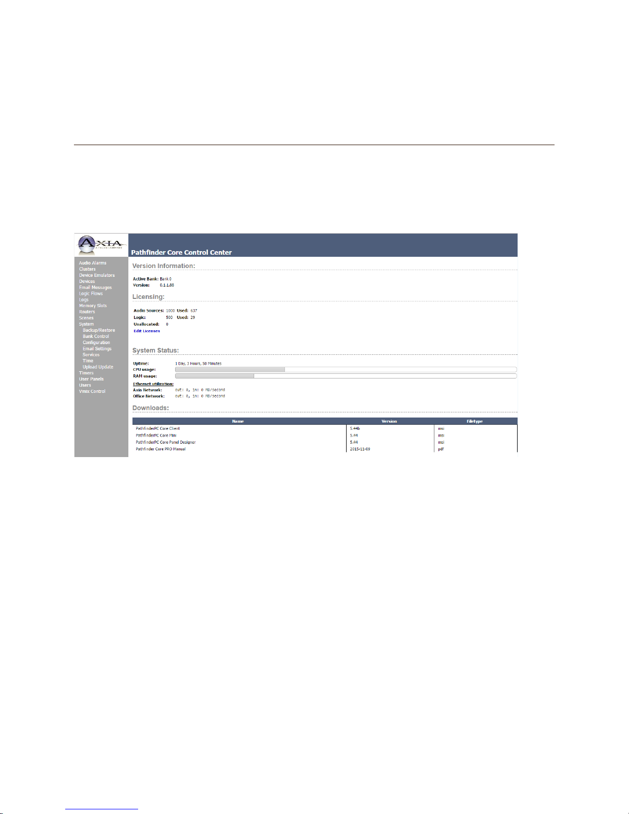
When you rst log in to the Pathnder Core PRO web page, you will be presented with the System status page. This
is the same web page that will display when clicking the System link in the navigation bar.
3: System • 7
This screen is informational only and does not provide anything that you can actually congure other than the
licensing. There are three sections.
Version
This shows which of the two rmware banks is currently active and the version of software that is running in that
bank.
Licensing
This shows the current license in the system and its capabilities.
System Status
This shows graphs representing the current CPU, memory, and Ethernet utilization. The graphs are updated
automatically every two seconds.
© 2017 Telos Alliance - Rev 1.2
Page 17
Downloads
This section provides download links for client applications that may be used with the Pathnder Core PRO system.
These client applications may be installed on any windows systems in your network. It is important to note that
these links may change when you upgrade the rmware in the system. After upgrading the rmware, it is always
a good idea to check this page and see if there are upgrades to the client applications. In most cases, older clients
will continue to work with new rmware versions, some functionality might be restricted as new features are added.
More information about these client applications can be found later in this manual.
Configuration
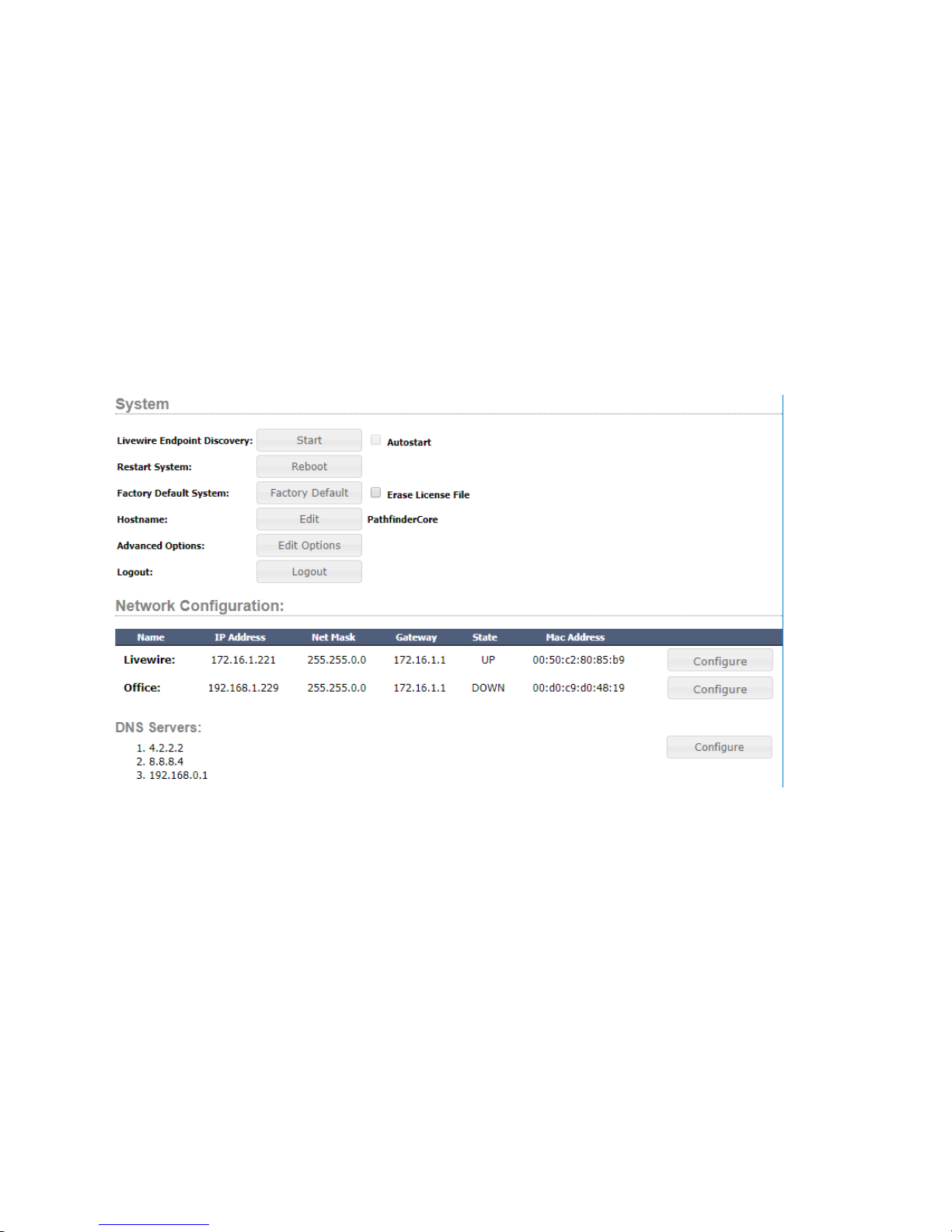
Under the System heading in the navigation bar is a conguration link. If you progressed through the Quickstart
section of this manual, you will already have been introduced to this page.
Livewire Endpoint Discovery
Clicking the start button on Livewire endpoint discovery will enable Pathnder Core PRO’s ability to detect new
devices on the network. When a new device is discovered, the system will add it to its device list and add any
route points provided by the device into the audio and GPIO router. This is one of the rst options you will use
when conguring a new system as it is how you will discover the equipment that Pathnder Core PRO can control.
When the discovery is enabled the button will say Stop instead of Start indicating that clicking the button will Stop
additional automatic discovery.
The “Autostart” checkbox allows you to dene that after restarting Pathnder Core PRO, discovery will
automatically be re-enabled. It is important to note that this is not a recommended setting. We recommend turning
discovery on to seek out your devices and then turning it back off again. Otherwise, if you plug a new device into
the network that has not been congured, it may get discovered before you have a chance to assign the IP address
you wish to assign to it. Pathnder Core PRO uses the IP address of a device as the unique identier of that device within
3: System • 8
the system. If you change the IP address of a device, Pathnder Core PRO will treat it as a new device. This is also why
we recommend setting up your basic Axia infrastructure rst, before introducing Pathnder Core PRO to the mix.
© 2017 Telos Alliance - Rev 1.2
Page 18
Restart System
If you click the “Reboot” button, the system will ask for conrmation to make sure the button was not accidentally
clicked, and it will then cause the system to reboot.
Factory Default System
If you click the “Factory Default” button, the system will ask for you to conrm the decision twice as this option
will erase all conguration data and return the system to the way it was shipped from the factory. It is highly
recommended that you make a backup of your system and download it to your local computer before using this
option. See the section of this manual on Backup and Restore for details. Select the Erase License File checkbox
if you also want to erase the licensing. It is important to note that erasing the license le will also erase the base
license and may require a call to support to relicense the system. Licenses are not currently included in the backup
le.
Hostname
Displays the current hostname of the Pathnder Core PRO. Click Edit to assign a new hostname to the system.
Hostname changes require a restart to take effect.
Advanced Options
This section if for use in consultation with Axia support only. It provides methods for changing certain system
functionality variables.
3: System • 9
Logout
Logs the current user out of the system and requests new login credentials.
Network Conguration
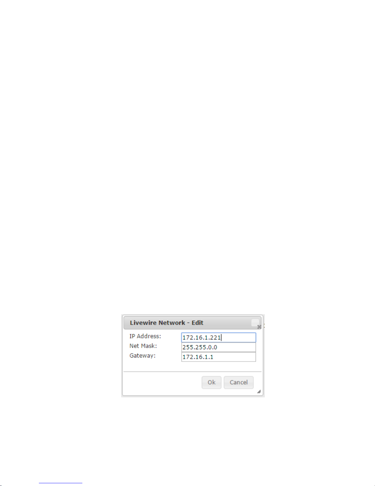
Livewire and Oce
In addition to conguring the IP addresses of the system via the front panel display, they can also be congured
using this web page. This section displays the current IP address information for each of the network interfaces in
the system. Clicking on the Congure button will present a dialog for editing the appropriate network interface
information.
Enter the appropriate IP address, netmask, and gateway and click OK. Or, click cancel to leave this dialog without
making any changes. IP Address changes will not take effect until you reboot the system. Therefore, after changing
the IP address you will notice that the conguration screen will now show the IP address changes in parenthesis and
a new reboot button will appear.
© 2017 Telos Alliance - Rev 1.2
Page 19
DNS
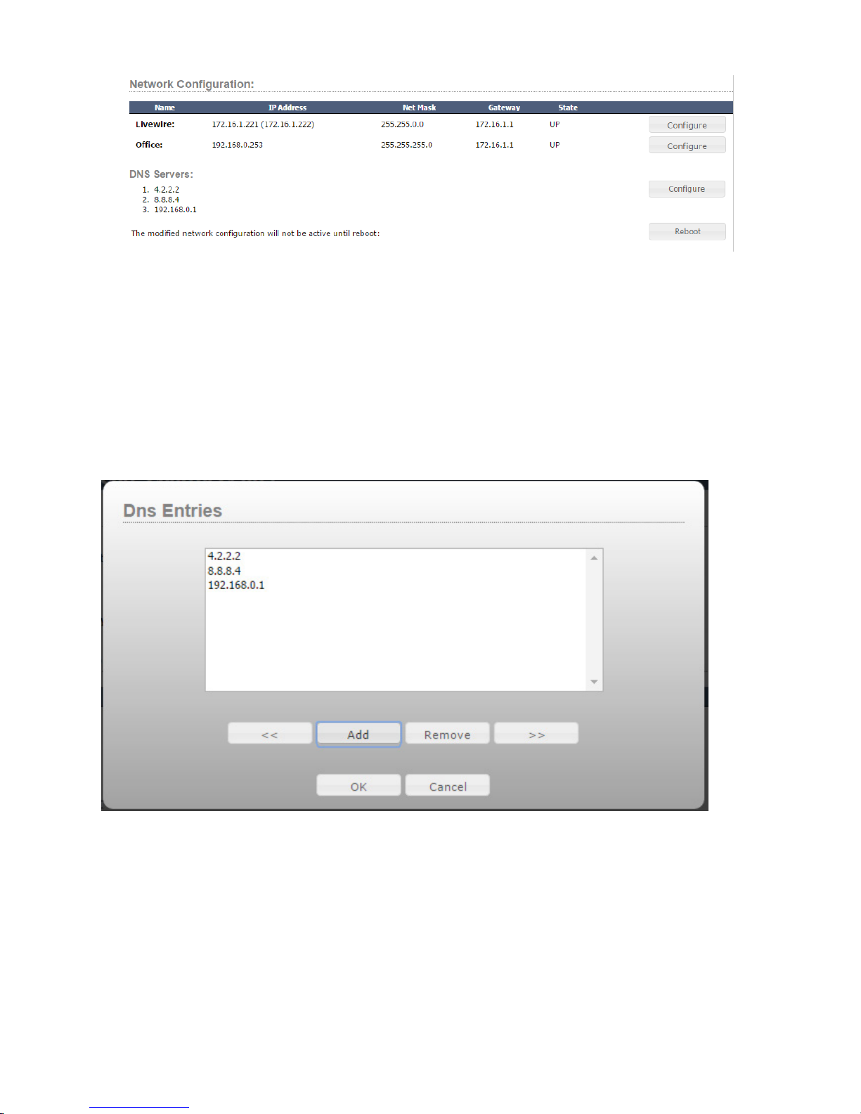
The DNS section lists the DNS servers dened in the system. DNS is important because the system can send emails
to alert administrators and employees of changes in your network that require attention. For example, you can send
emails when critical sources or destinations such as air chains become silent. In order to do this the system needs
to be able to resolve email server names with the correct IP addresses to send the email through. The DNS entries
can also be used when entering NTP server information. Talk to your network administrator if you are unsure what
DNS servers to use.
If you click on the Congure button you will be presented with a dialog that will allow you to add and remove DNS
servers and also change the order in which the system will attempt to use them.
Click the Add button to add a new DNS server to the list. Select a DNS server in the list and click Remove to
remove a DNS server. Select a DNS server in the list and click the << or >> buttons to move it up and down in
the priority list. Click cancel to leave the dialog without making any changes, or OK to save your changes to the
system. DNS changes do not require a reboot to become active.
3: System • 10
© 2017 Telos Alliance - Rev 1.2
Page 20

Licenses
Each Pathnder Core PRO system should come from the factory with a base license that allows 500 Axia audio
sources and 500 logic ows. Additional licenses to add functionality may be purchased through your Axia
distributer. Each additional license provides an additional 500 Axia audio sources or 500 logic ows. Each
hardware Pathnder Core PRO requires a base license. But the additional licenses are shared between the Pathnder
Core PRO units that are participating in a given clustered system. This means that if you need a redundant
Pathnder Core PRO system that supports 1000 Axia audio sources, you will need to purchase two Pathnder Core
PRO systems (each of which comes with a base license), and then a single add-on license to add the additional 500
sources. The add-on license allows both systems in the cluster to mirror and synchronize a router with 1000 sources.
Please note that virtual sources and gpio sources do not count against the license. Only Axia audio sources whose
streams are enabled and logic ow endpoints are counted in the licensing. If you have questions regarding the
licensing model, please contact Axia support or your Axia distributor.
In order to view or add additional licenses, click on the System heading on the navigation bar and then click the
“Edit Licenses” link.
The licensing page will display your base license information. It will also provide a list of your additional licenses.
Click the New License line and enter the new Request Code and License Key to add a new license. Then select
whether the new extended license should be applied to routes (sources) or logic ows. Finally click Submit
Changes to add the license to the system. License changes will require a reboot to become effective. Click the
Conguration link under System to nd the reboot button.
Backup/Restore
The backup and restore page presents a list of all backups in the system.
3: System • 11
© 2017 Telos Alliance - Rev 1.2
Page 21
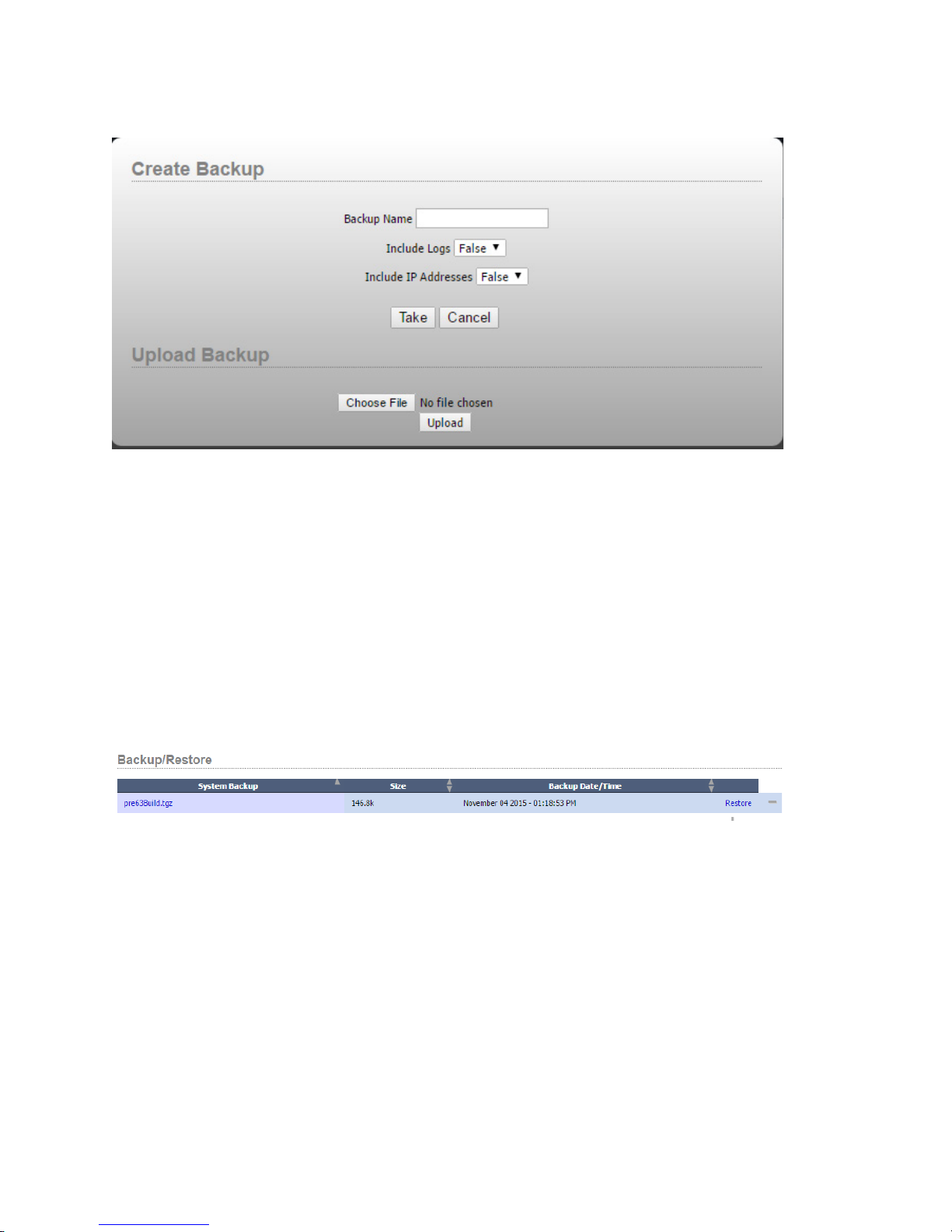
If this is the rst time using this page, there will probably not be any backups present in the system. To make a new
backup, or to upload a backup from your local computer back into the system, click the plus icon.
In order to create a new backup, enter a name for the backup, select whether you want logs and/or the IP address to
be included in the backup and then click Take. If you are intending to restore the backup on a different Pathnder
Core PRO, you may not wish to include the IP address so that the restore process does not overwrite the IP address
of the other unit. Clicking Cancel will exit the dialog without making any changes. It is important to note that the
backup will include any conguration les needed to return your system to its current state. If logs are included it
will also include all system and application logs that are currently on the system. The log information can be very
useful to tech support if they are trying to assist in troubleshooting an issue. It is likely they will ask you to take a
backup including log les and send it to them.
In the case you are trying to restore your conguration to a new system, a factory default system, or a system that
has had the desired backup removed from the system, click the choose le and select a Pathnder Core PRO backup
le on your local system. Then click upload. After doing this the backup will be available in the list of backups on
the preceding screen.
After taking a new backup it is highly recommended that you click on the link to the backup le and download it
to your local computer to store it in a safe location. Backups that live on the Pathnder Core PRO system are not
true backups because if the system or storage medium were to fail, both the system and the backups could be lost.
Downloading a backup to your local system will also allow you to send the backup to support if necessary.
The minus icon will delete a backup from the system. Since there is limited space on the storage medium it is only
recommended to keep a few backups on the system at a time.
Clicking the restore icon will request conrmation that you really wish to restore the system to that state and then
it will shut down the Pathnder Core PRO services, restore the conguration les to the state of that backup, and
reboot the system.
3: System • 12
It is very important to understand this process. While the restore function is usually pretty quick, the system will not
be functioning during the restore and reboot operation.
© 2017 Telos Alliance - Rev 1.2
Page 22
Upload Update
One of the most important tasks the Administrator of Pathnder Core PRO will have to perform is periodic rmware
updates. This project is undergoing a very active development lifecycle with many new features planned for future
versions. That, in addition to xes for any bugs that are reported to us by our users, will require occasional updates
of the rmware in your Pathnder Core PRO system.
The system has two banks for software versions so that if there is a need to return to an earlier version, it will live in
the preceding bank. The process for upgrading your system is as follows.
• Take a backup of your system as explained in the previous section of this manual. We always recommend
backing up your system before any major change just to be safe. The backup process will actually generate
its own backup as well, but it never hurts to have a safety stored on your local computer.
• Download the new rmware version from the Axia Audio web site to your local computer. The le name
extension will be .pfc_upd which stands for Pathnder Core PRO update package. It is also a good idea to
take a moment to scan the release notes to understand the changes between the version you are currently
running and the version to which you will be upgrading.
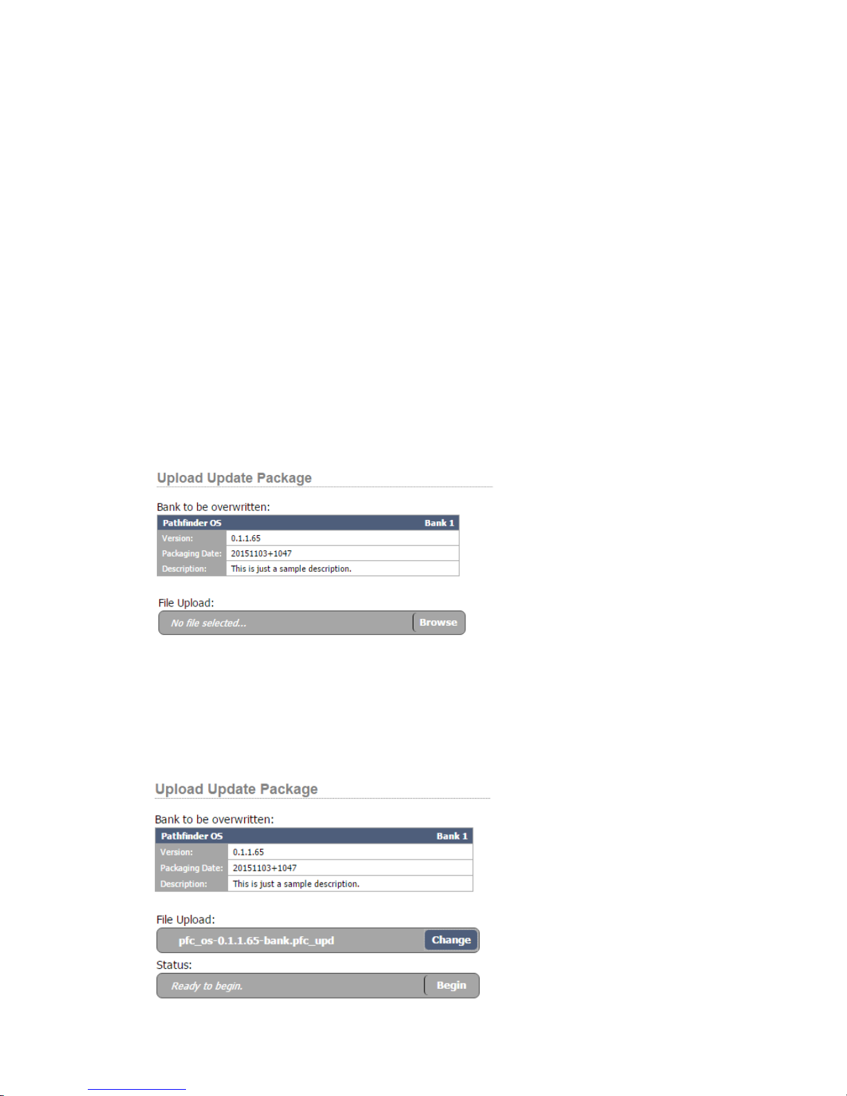
• Select the Upload Update link under the System heading in the navigation bar.
3: System • 13
• This page will display the bank on which you are not currently executing. The update will always update
whichever bank is not currently executing. So if you are currently running on bank 0, the update process
will update bank 1.
• Click the Browse button and select the le you downloaded from the Axia web site.
© 2017 Telos Alliance - Rev 1.2
Page 23
• The File Upload bar will change to the name of the le which you have selected to upload to the system
and a status bar will appear with the begin button.
• Click Begin to begin the updating process.
• A new page will appear with a progress bar that presents stages and some additional information regarding
what is taking place at each stage of the upgrade process so that you can monitor the progress of the update.
The update may take several minutes to complete.
Important Note: It is important to understand the status of the conguration les during an upgrade
process. The conguration les for the system reside within the currently executing bank. During the
upgrade process, a backup of the conguration from the currently running bank is automatically made.
After the new sof tware is written into the new bank, the conguration is then restored into the new bank
so that when you boot into the new bank it has the same conguration that is in the currently executing
bank. However, if you then boot into the new bank and make changes to the conguration in the new
bank, those changes will not reside in the old bank. If you wish to return to the old bank and you have
made changes to the conguration, you should back up the conguration on the new bank, boot into the
old bank, and then restore the backup. This process is outlined in the section on Backup and Restore.
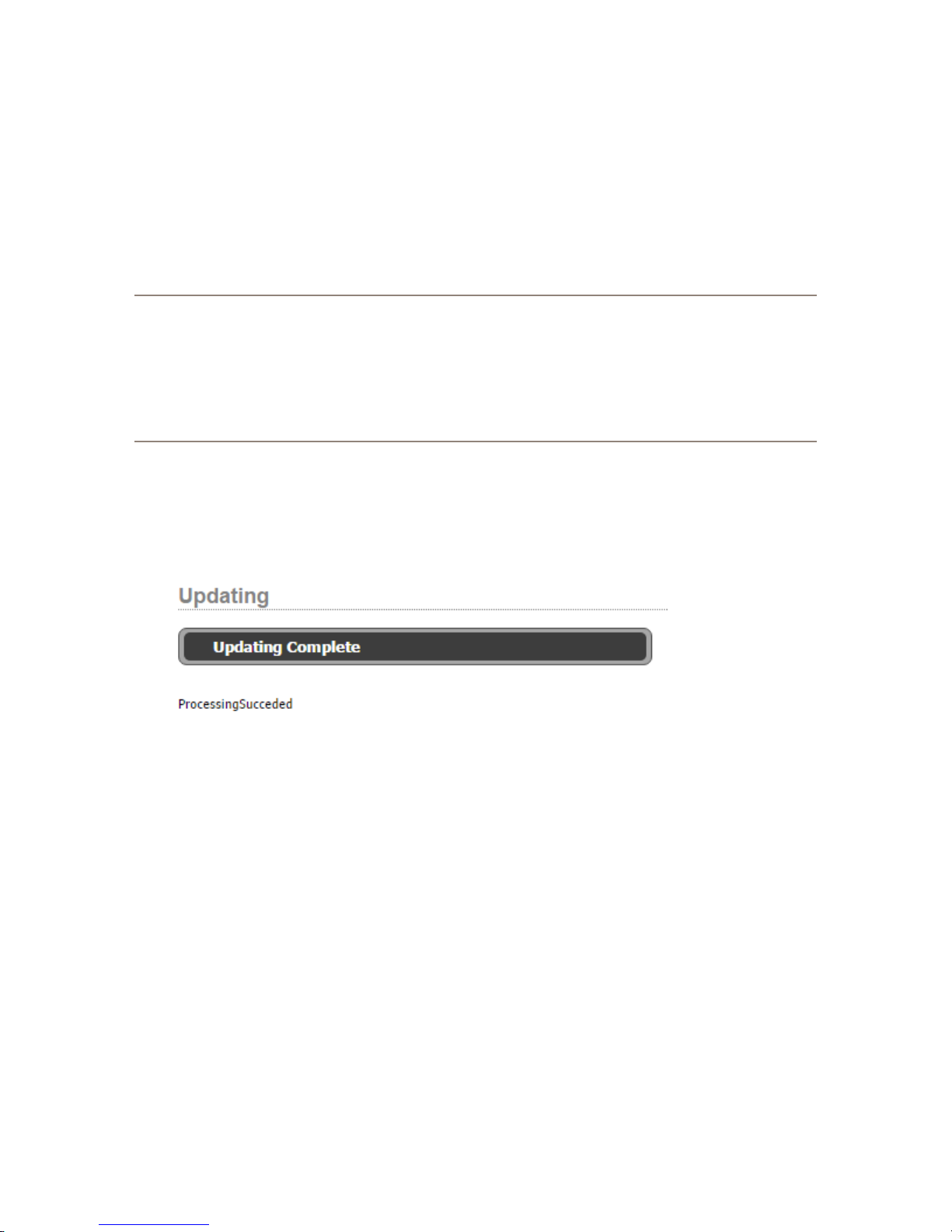
• Once the update is complete, you should receive a Processing Succeeded message. If you receive an error
message instead of processing succeeded, please contact support. Because you are updating the bank
which is currently not executing, the system should continue to run even if there was an error with the
update.
• In order to actually boot into the updated bank and start using the new software, click the Bank Control link
in the navigation bar.
3: System • 14
© 2017 Telos Alliance - Rev 1.2
Page 24
Bank Control
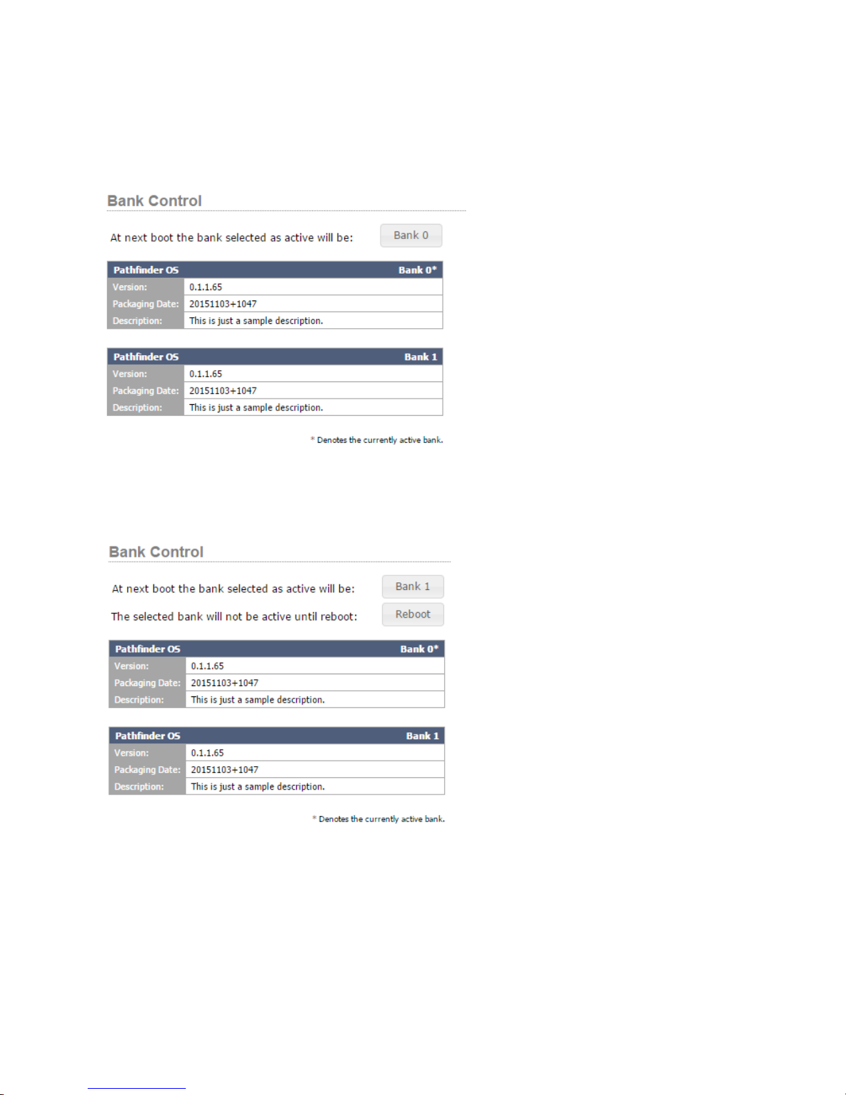
Bank control displays the software versions in both banks of the system and offers control over the currently
executing software revision bank. Click the bank control link under the System heading in the navigation bar to
view this page.
The bank button can be used to switch which bank will be used on the next reboot. It also displays the bank that is
currently selected as the next bank that will be booted at reboot. After changing the bank that will be used on next
reboot, a reboot button will appear on the page.
Clicking on the reboot button will reboot into the newly selected bank.
The information tables display the software version in each bank. An asterisk will be present next to the bank that is
currently executing.
3: System • 15
© 2017 Telos Alliance - Rev 1.2
Page 25
It is important to understand some features of the bank selection process. When you select a new bank, the system
creates a temporary mark in the system to boot into that bank. After the system boots into the new bank, that
temporary mark is turned into a normal reboot setting so the newly selected bank will be used on subsequent
reboots. This is called cementing the bank. The reason this is important is that if something goes wrong with the
upgrade and the bank is unusable, the bank does not get cemented and rebooting the system either automatically or
by disconnecting power will cause the system to boot into the previously working bank. The new bank will only get
cemented for future boots if it boots successfully.
This also means that after rebooting into a new bank you should return to the bank control web page to make
sure the boot was successful and you are executing on the desired bank. If the boot fails, it could fail back to the
previous bank and you will only know that by double checking this page.
Important Note: We have occasionally seen some browsers try to cache the state of this page even
though we have requested in the web page code that the browser does not cache this data. So if you
reboot and the executing asterisk does not change, try refreshing the web page. Some browsers have an
extra button you can hold down while refreshing to force the web page to refresh rather than rely on the
cache. For example with google chrome, hold Shift and Cntrl while clicking the refresh icon to forcefully
reload the page.
It is also important to understand the state of conguration les between bank changes. Conguration les
reside within the executing bank. Therefore, if you are switching to a different bank the conguration may be
different. So it is recommended to take a backup of your conguration before switching banks, and then restore
that conguration on the new bank. If you are switching banks immediately after upgrading the rmware, then
this backup and restore has been already completed as part of the upgrade process. Otherwise, it is recommended
to review the backup and restore procedures earlier in this manual. Conversely this also means that if you make a
mistake in the conguration in a new bank, you can boot back into the old bank to get to an older and successfully
working conguration. Though using backups and restores is a more efcient way of doing this.
3: System • 16
Services
Click the Services link on the navigation bar to view the Services page.
This page will only be used in conjunction with a session with Axia tech support, but it is worthwhile discussing
what this page represents. In an effort to make Pathnder Core PRO as robust as possible, the system has a
sophisticated watchdog process. This process monitors the state of each of the services in the system. It is
responsible for sending ping messages to each service to make sure they are still responsive at the application layer.
If a service fails to respond within a certain period of time, the watchdog will restart the service. In a rare and
catastrophic situation where the watchdog is not able to achieve proper responsiveness of a service, it might also
restart all services or even after enough subsequent failures, reboot the system.
© 2017 Telos Alliance - Rev 1.2
Page 26
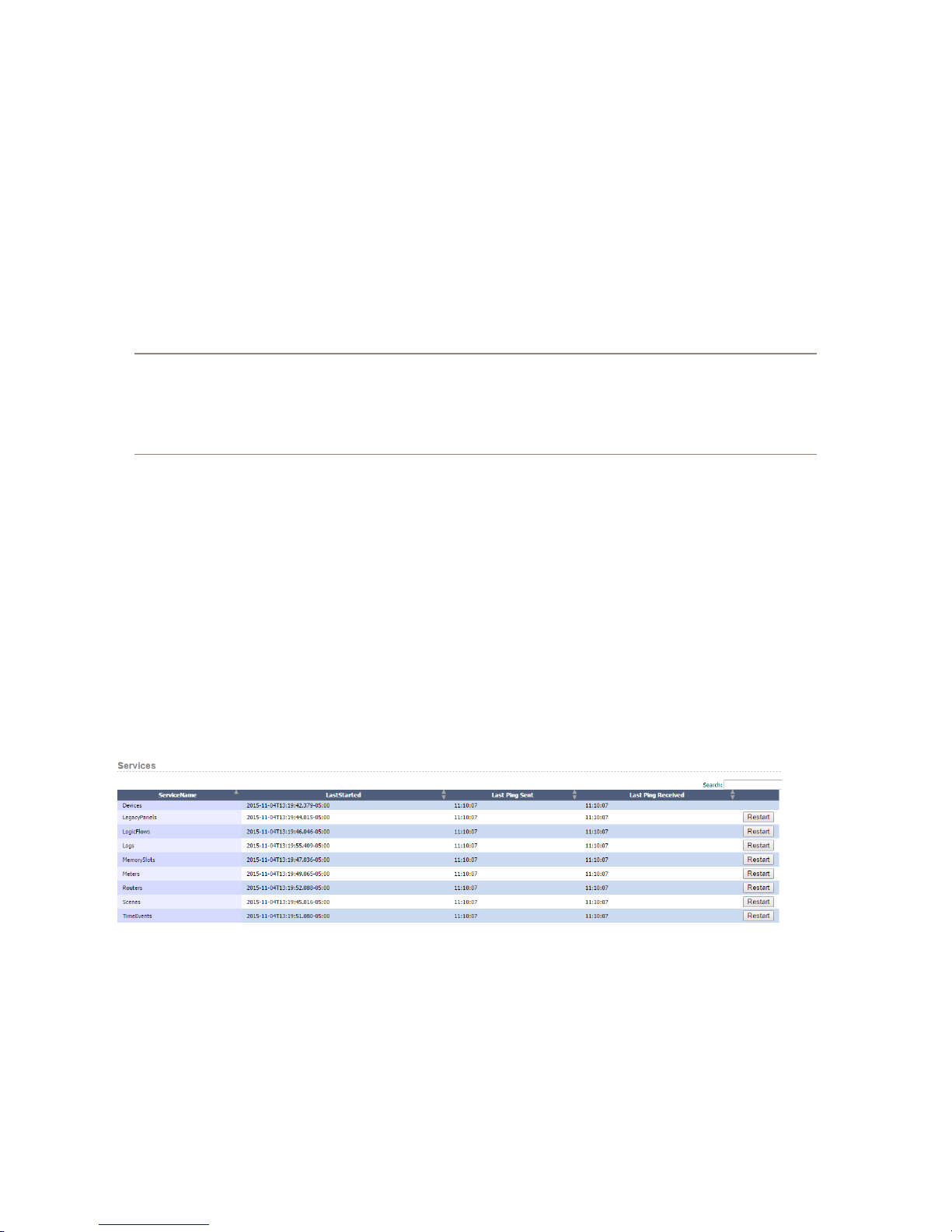
This screen shows each service, when it was last started, and the most recent ping and response time. If you watch
this screen you should notice the pings changing at approximately 5 second intervals.
Each service also has a restart button. This allows an Administrator to manually restart a service should Axia
support request an individual service restart. You may notice that the Devices service does not have a restart
button. This is because the devices service acts as a parent to all of the other services. Therefore restarting the
devices service is virtually equivalent to restarting the entire system which can be accomplished from the System
Conguration page.
In many ways, this page is equivalent to the services control panel in a Windows machine.
Time
Click on the Time link under the System heading of the navigation bar to view the Time settings.
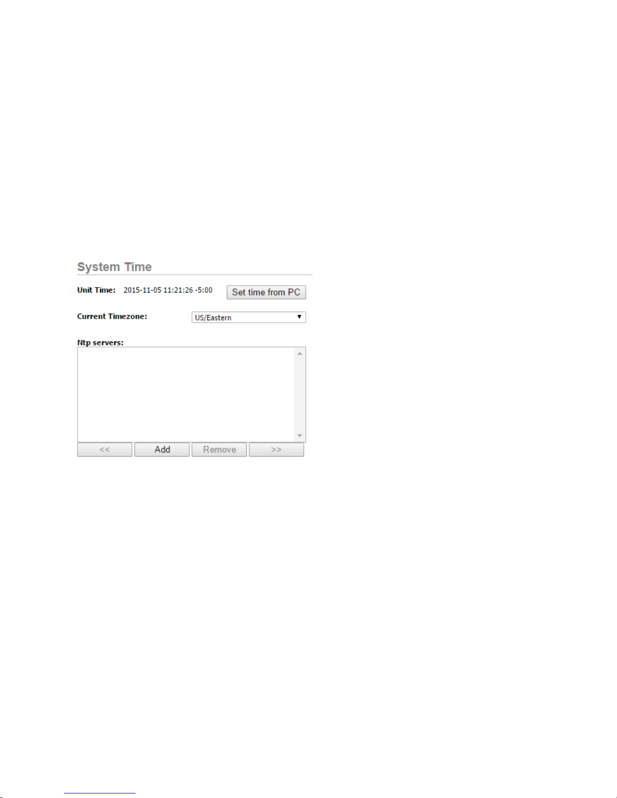
The System Time conguration page allows you to dene NTP servers, set the system’s time zone, and sync
the current time to that of your local PC. Use the time zone drop down to dene the correct time zone for the
system. Click the Set time from PC button to update Pathnder Core PRO’s current time to that of your local PC.
Or preferably enter NTP servers into the list so that Pathnder Core PRO can update its time automatically and
therefore always be as accurate as possible.
There are a number of reasons why it is important to keep Pathnder Core PRO’s time accurate. The rst is that
the system has the ability to dene events to happen at specic dates and times. Those events will of course, re
at incorrect times if the system’s time is not up to date. Additionally, log les use the system’s time settings to log
when changes happen. And nally, proper cluster synchronization relies on date time settings to determine whether
a specic piece of information is more up to date on one system or another and therefore whether a synchronization
of that piece of information needs to take place. Therefore it is highly recommended that you use NTP servers
to guarantee accurate time in your Pathnder Core PRO system. Talk to your network administrator if you have
questions about which NTP servers to use.
3: System • 17
© 2017 Telos Alliance - Rev 1.2
Page 27
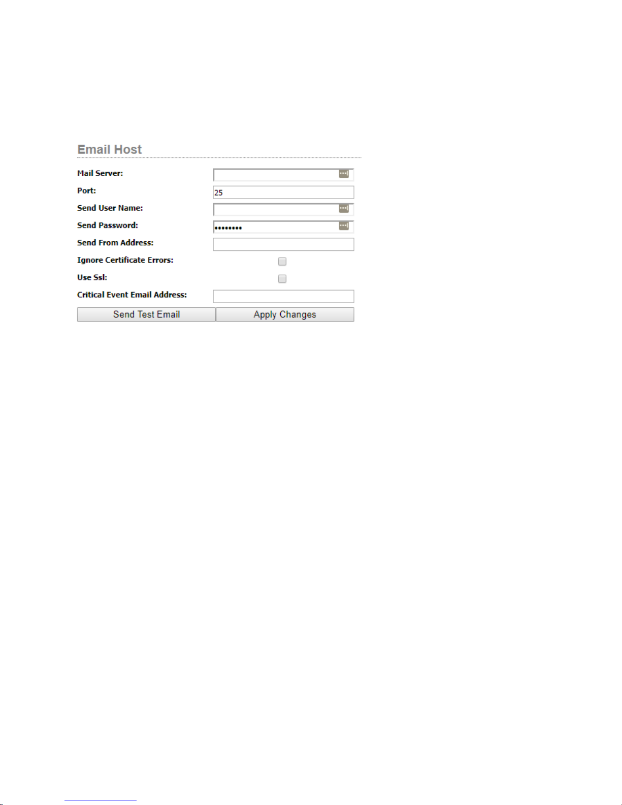
Email Settings
In order to send emails from logic ows, the server parameters must rst be dened in the system in order to let
Pathnder Core PRO know which email server to use to send email messages. Under the system section of the
navigation bar, click on the Email Host link.
These settings are similar to those used by any other email client application. The ignore Certicate option however
requires some explanation. If you are using SSL encryption and the SSL certicate chain provided by the host is
not in Pathnder Core PRO’s trusted list, then the message will not be sent and an error will be generated. Enabling
this option will cause the system to use SSL encryption but ignore the SSL certicate error and send the message
anyway. Once you have the parameters congured correctly, click “Apply Changes” to store the parameters to the
system. Then use the “Send test Email” button to generate a test email. The page will ask for an email address
to send the test message to and will then attempt to send the message. Any errors will be reported. Once you can
successfully send test emails, you are ready to create messages that may be used by Pathnder Core PRO’s event
system – Logic Flows.
3: System • 18
Go to the Email Messages section of this manual for more details about creating email messages which the system
can send and how to determine when those messages are sent.
The Critical Event Email Address eld may be used to alert an email address of critical issues that take place such as
a system restart or a service failure.
© 2017 Telos Alliance - Rev 1.2
Page 28
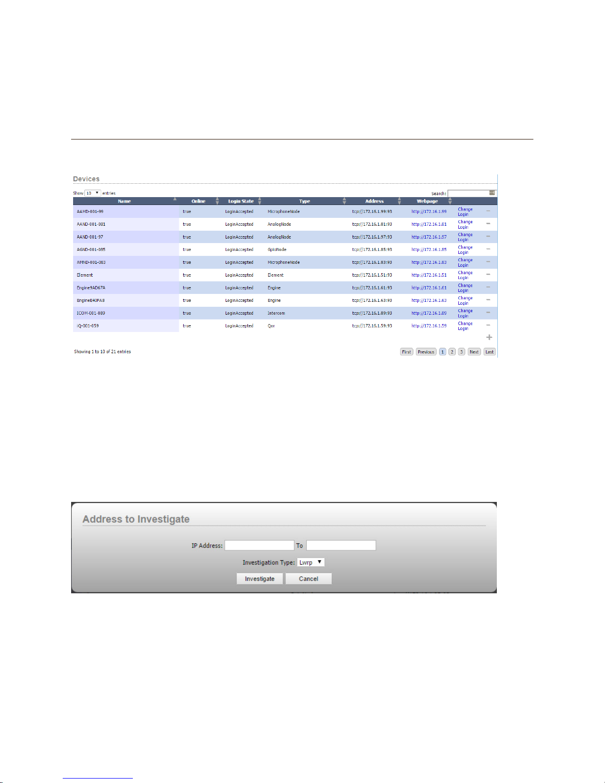
Chapter 4
Devices
The Devices link in the navigation bar displays a list of all of the devices which Pathnder Core PRO has
discovered.
Each device entry in the list also includes a link that will take you directly to the device’s conguration web page.
There’s another link that allows you to dene a different login password required by the device. You can use the
minus icon to remove a device from the system. When a device is removed from the system, it will also remove all
entries in the Audio and GPIO router for that device. It is important to note that if Livewire Discovery is enabled on
the system page, the device may get rediscovered and added back in to the list if it is still on the network.
There are some devices that are not discoverable automatically. These include the OLED and LCD rackmount
button panels. Additionally, you may want to add a device into the system without enabling the full network
discovery engine. To add these into the system, click the Add button.
A dialog box will appear that allows you to dene a range of IP addresses to scan and the investigation method to
use. If you are adding a single device enter the same IP address in both boxes. The “To” box should auto-populate
when you enter an IP address into the IP address box. If you are adding an Axia Audio or GPIO device, select Lwrp
as the investigation type. If you are adding a rackmount OLED or LCD panel into the system then use the Lwcp
investigation type.
Clicking investigate will cause the system to try and contact a device on the requested IP address using the dened
4: Devices • 19
investigation type. If a device can be contacted and data can be discovered from the device, then it will be added
into the devices list. Its routing resources will also be added into the requisite routers.
© 2017 Telos Alliance - Rev 1.2
Page 29
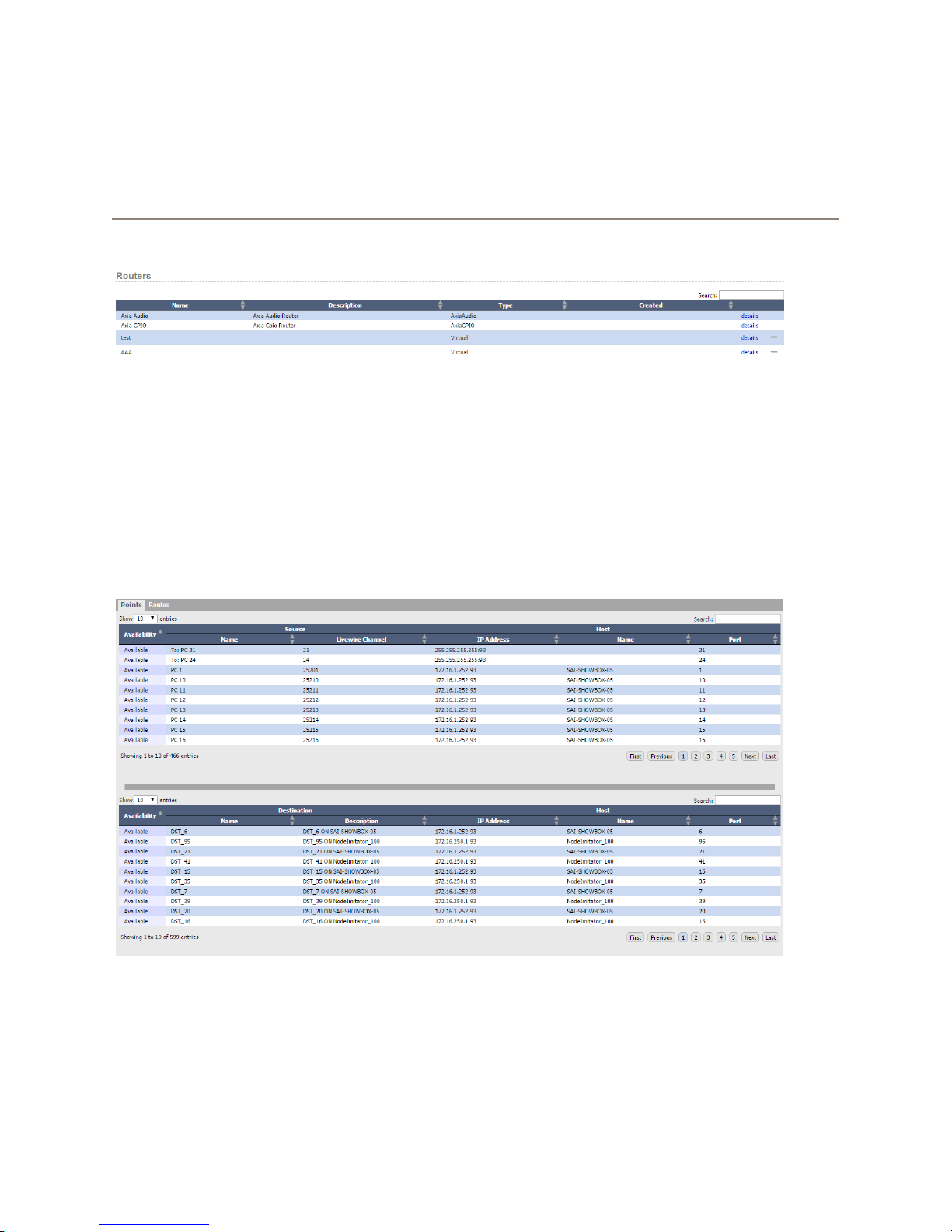
Chapter 5
Routers
Clicking on the Routers link in the navigation bar will present a list of routers in the system.
Pathnder Core PRO currently supports Axia Audio Routers, Axia GPIO Routers, and Virtual Routers. The Axia
Audio Router and Axia GPIO Router are automatically generated based on the devices that are discovered in the
system. These two routers will always be in the system and may not be removed.
Virtual Routers may be created and removed from this page or using the PathnderPC Client application. More
information regarding the different types of routers is discussed later in this section.
Clicking on the details link for any router will present a new screen with lists of all the sources and destinations that
make up the router.
This screen has two tabs on the top - points and routes. Selecting one tab or the other will display the data relevant
to that tab.
5: Routers • 20
© 2017 Telos Alliance - Rev 1.2
Page 30

Points
The points tab simply shows a list of all of the sources and destinations in the router along with relevant information
for each source or destination. The columns in each list are broken into two major sections – Source/Destination
and Host. The left half of the table shows columns related directly to the source or destination such as the source’s
name, Livewire channel, and availability. The right half of the table shows information about the host device where
that source or destination resides.
• Availability – This means whether the source or destination is currently available for use. If a device is
ofine or unreachable, this column may show ofine. It may also show “SystemLocked” for destinations
whose source cannot be changed by the router. For example, mixer faders cannot be changed using standard routing commands. They must be changed using the console or by issuing special source prole load
commands. Therefore, they will display as System Locked.
• Name (Source/Destination) – The Name of the source or destination.
• Livewire Channel (Axia Audio Sources Only) – The Livewire channel number assigned to the source.
• IP Address – The IP Address of the host device on which the source or destination is located.
• Name (Host) – The name of the device on which the source or destination is located.
• Port – The physical (or virtual) port number that identies the source or destination on the device.
Since these lists can contain a large number of entries, the search box can be used to narrow the list.
For users that have administrative rights to the router some additional conguration tools may also be present
depending on the type of router. For example, when viewing the Axia Audio router, a button will be present for
adding Aes67 sources to the router. In the Virtual router, controls will exist for adding additional virtual sources and
destinations to the router. These additional controls will be discussed below under the section for each router type.
5: Routers • 21
© 2017 Telos Alliance - Rev 1.2
Page 31
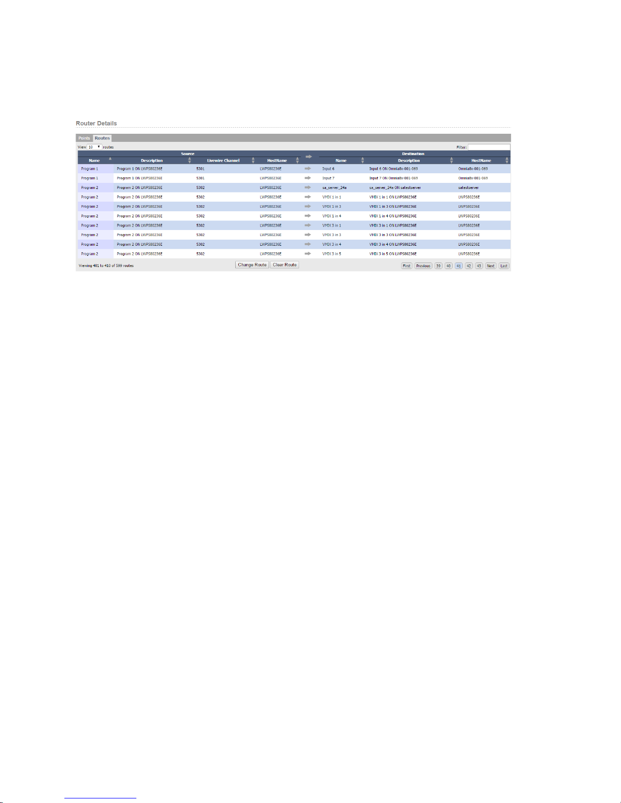
Routes
The Routes tab displays the current source to destination routing of the router.
Again, this screen is divided into two sides. The source information for each active route is on the left, and the
destination information is on the right. The columns display the information about each active route.
• Source
» Name – The name of the source routed to this destination.
» Description – The description of the source routed to this destination.
» Livewire Channel (Axia Audio Router Only) – The Livewire channel number of the source routed to
this destination.
» HostName – The name of the device where the source resides.
• Destination
» Name – The name of the destination.
» Description – The description of the destination.
» HostName – The name of the device where the destination resides.
5: Routers • 22
© 2017 Telos Alliance - Rev 1.2
Page 32
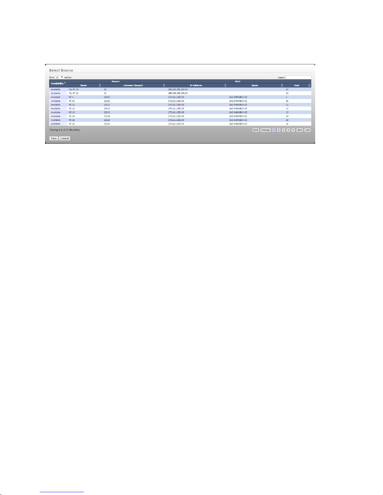
Route changes may also be made from this screen by clicking a line in the list and then clicking the “Change Route”
button, or by double clicking on any line in the routing list. Either of these actions will present a dialog with a list of
sources that may be assigned to the currently selected destination.
Select the source in the list and select “Take” to change the route. Or simply double click on any of the sources
in the list. Clicking cancel will exit the route selection dialog without making any changes. Again, these lists can
be lengthy so use the search function to narrow down the selections. The search lter can be remembered as you
navigate between pages so if you return to the route page and are not seeing sources or destinations that you expect
to nd, check to see if there is a search lter on the list. It is also important to notice that a source will not be
found in the Routes list if it is not routed to anything. It will be present in the Take list when you go to make a
change as well as in the Points tab under sources. But the search function is only searching data that is in the list.
If the source is not routed to any destination, it is not in the routes list because it is not involved in any active
route.
Routers can also be controlled by the Pathnder PC_Core Client application. See Chapter 18 Pathnder PC_Core Client.
Router Types
Axia Audio Router
The Axia Audio Router is automatically created by the system. As devices get discovered or manually added into
the system they are analyzed to determine what audio sources and destinations they provide and those sources and
destinations are automatically loaded into this router. When you use this router to make a router change, Pathnder
Core PRO is reaching out into the destination device and sending it a command to change the source assigned to that
destination. This happens in much the same way as you could make the change from the device’s web page except
that you can see all of the audio I/Os in one location with Pathnder Core PRO. Pathnder Core PRO can also
execute scene changes where it can make hundreds of route changes across many devices at once.
You may notice in the points tab that some sources will carry an IP Address of 255.255.255.255:93 and will have
nothing in the host name column. These sources will also have “To:” at the start of the Name. These sources are
Axia Backfeeds generated by the mixing engines. They are not assigned a specic host because they are the one and
only type of source that can dynamically change which device (Engine) is currently hosting them. So they do not
have a formal home. To learn more about Axia Backfeeds, see any of the Axia Mixing Console manuals.
5: Routers • 23
© 2017 Telos Alliance - Rev 1.2
Page 33
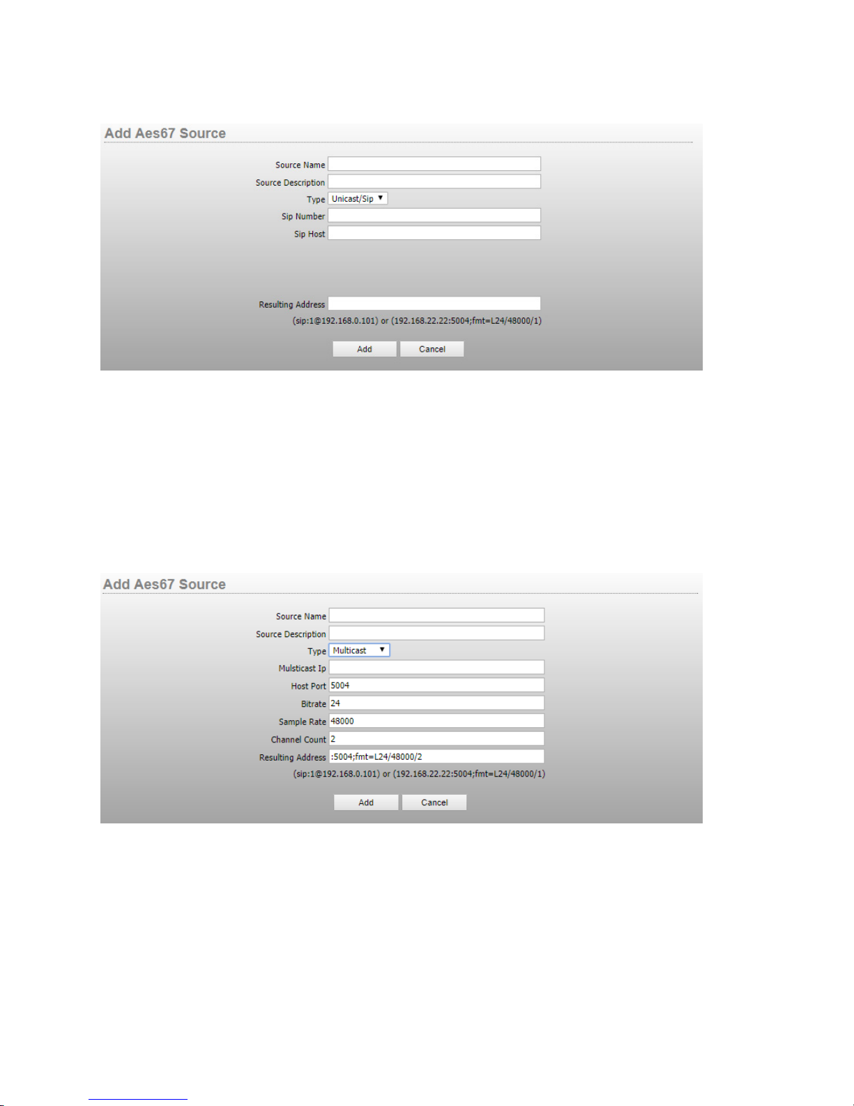
The points tab of an Axia Audio Router will also have an Add Aes67 Source button. Clicking this button will
present a dialog for adding Aes67 sources to the system.
Use the Source Name and Description elds to dene the name and description by which the source will be
identied in the system. The Aes67 specication allows for sources to be dened using a Unicast/Sip or multicast
address format. The information required to dene the source is different depending on the selected format and
so different elds will be present depending on which denition you select. The example above shows the unicast
method. Dene the number and the host IP address required to dene the sip path. The resulting address eld will
automatically ll with the address required for this source based on these parameters.
If you select the multicast option the required elds will change to look like:
In this case ll in the multicast IP address and adjust the other parameters to reect the Aes67 source settings and
click add to add the source.
Once added you will notice that in the list of points, Aes67 sources will have a minus icon to allow deletion of the
source and an edit eld to return to the editing dialog shown above.
Once these sources are added to the router, PathnderCore PRO can instruct any Axia device destination that
5: Routers • 24
supports Aes67 streams to receive a specic Aes67 stream in the same way as normal Axia route changes are made.
© 2017 Telos Alliance - Rev 1.2
Page 34

Axia GPIO Router
The Axia GPIO Router is very similar to the Axia Audio Router. As devices get discovered which have GPIO
ports, those ports are added to this router. And in a similar fashion to the Axia Audio Router, when you make route
changes, Pathnder Core PRO is reaching into the destination node and sending it a command which tells a specic
GPO on that device to follow the GPIs of the selected source device and port. Due to the nature of GPIOs on an
Axia network, this routing becomes a little more nuanced and could use some explanation.
There are three ways to route GPIO closures across an Axia network. The Axia GPIO Router in Pathnder Core
PRO only uses one of these methods. It is important to understand all of the methods because if you try to use
conicting methods at the same time on a GPIO port, that port can cause erroneous and unpredictable closures.
First, within the Axia device itself you can assign a channel number to a GPIO port. When you do this, you are
creating a special situation where you are telling the port to bind itself to Axia Mixing Console GPIO signals from
whatever console currently has loaded that Livewire channel number.
Second, you can assign an IP address and port number of a GPI to a GPO. This is called snake mode and it is what
the GPIO Router uses to tell a device’s GPOs to mirror another port’s GPIs. Therefore, when you make a route
change in the Pathnder Axia GPIO Router from Node 1 port 1 to Node 2 port 4, any GPI closures on Node 1 port
1, will be mirrored as GPOs in Node 2 port 4. And these route changes can be updated dynamically, just as with any
other router.
5: Routers • 25
The third way that GPIOs can be used is to leave both the Livewire channel number and the routing assignment
unassigned and then directly trip the closures using Pathnder’s (or some other automation system’s) event system
by sending closure commands to the device.
The reason it is important to understand these three methods of GPIO closures is that it is possible to do multiples of
them at the same time which is occasionally useful but more often, just a mistake. For example, we often see users
who think that the GPIO ports should have a Livewire channel number and so just arbitrarily assign them. Then you
can get into a situation where they have created Pathnder events to make and respond to changes on those ports but
those same ports are also being red by changes on the mixing console causing confusion and calls to Axia Support.
It is important to understand how you intend to use a given GPIO port, and congure it correctly for that task.
Virtual Routers
Virtual routers are a special kind of router. You can think of a virtual router as a way to make a subset of routes
you wish a specic user to use. For example, you could create a router that only contains the routes from the Axia
Audio Router that are related to a specic studio. Or you could create a router that only contains the routes that
are relevant to the nal air chains. This allows you to create purpose driven routers that display only the routes
that are relevant to a specic set of tasks and are therefore much easier to navigate than browsing every source and
destination on the entire network.
However, virtual routers can also go much deeper than just subsets of routes. For any specic virtual source or
destination, you can also associate multiple real sources or destinations with that virtual source. That sounds
complicated but actually it is relatively simple and extremely powerful. For example, let’s say that every time you
route a specic Audio Source to a specic Audio Destination, you also want to route a GPIO source that carries
signaling information related to that audio source to a specic GPIO destination. An example of where this might
be useful would be switching from a primary automation system to a backup automation system. You could use
a Virtual Router to do this. Create a virtual source that contains both an audio and a GPIO source, and a virtual
destination that contains both an audio and a GPIO destination. Now, when you use the virtual router to route that
© 2017 Telos Alliance - Rev 1.2
Page 35
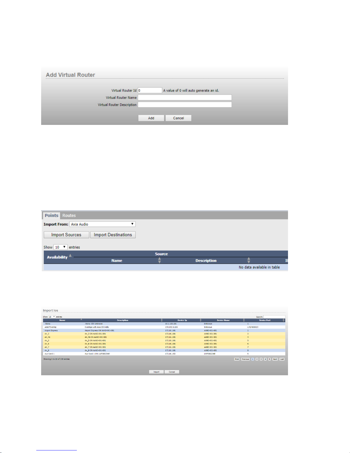
source to the destination, the virtual router will tell the underlying audio and GPIO routers to make both routes.
In order to create a virtual router, click the plus icon on the main routers page.
Provide a name and description for the router and click Add. The router id will autogenerate the next available
router id number. That can be overridden with your own id number as well. Be careful to use a unique id that is not
already in use by another router.
After clicking Add, the virtual router will appear in the routers list. However, this router is currently empty. It does
not have any sources or destinations. Click the details button and select the points tab. You will notice that there are
several controls at the top of the points tab.
5: Routers • 26
The easiest way to populate a virtual router is to import some sources and destinations from a real router. In this
case we are going to select the Axia Audio Router from the import from drop down and then click Import Sources.
You will then be presented with a list of sources you can select to import into the virtual router.
Click on the sources you wish to import (Shift-click to select as range) and click the import button. Repeat the
procedure with the Import Destinations button to import destinations into the virtual router.
© 2017 Telos Alliance - Rev 1.2
Page 36
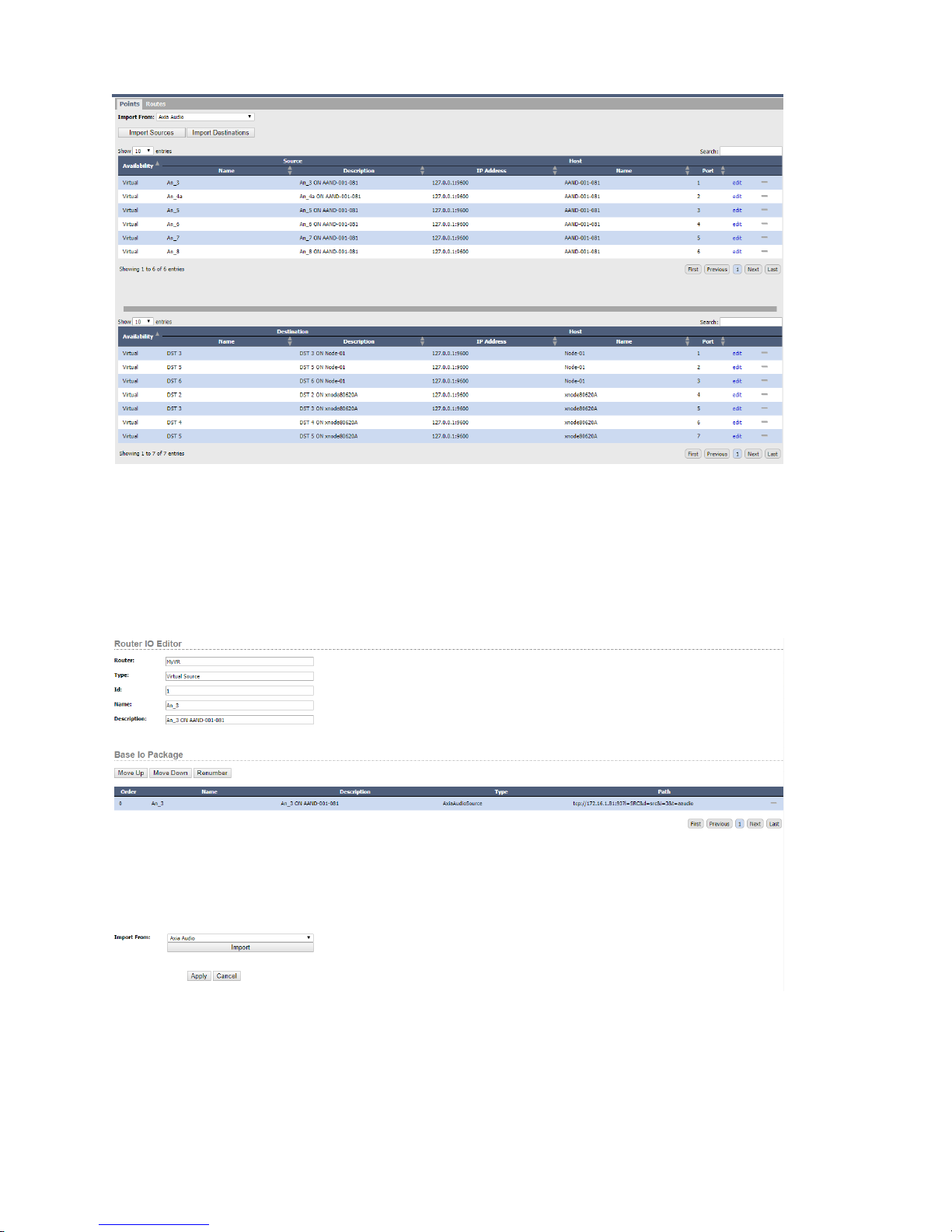
At this point you have a virtual router with only the sources and destinations you want available. This router can
then be made available as the only router certain users have access to using the user rights section or it can be used
to easily see and change certain critical routes without viewing the entire Audio router.
However, let’s dig a little deeper into each individual virtual IO. If you click the Edit link on one of the imported
virtual sources you will be presented with more details about the virtual source.
By default, when you import a source, the name and description elds of the virtual source inherit the name of the
imported source. But you can change this to any name or description you want using the name and description eld.
The Base Io Package allows you to dene which real sources are a part of this virtual source. As mentioned earlier,
it is possible to tie multiple sources together into a single virtual source package. So, for example we could select
5: Routers • 27
the Gpio router from the import from dialog, click import and select a gpio source to include in this package.
© 2017 Telos Alliance - Rev 1.2
Page 37
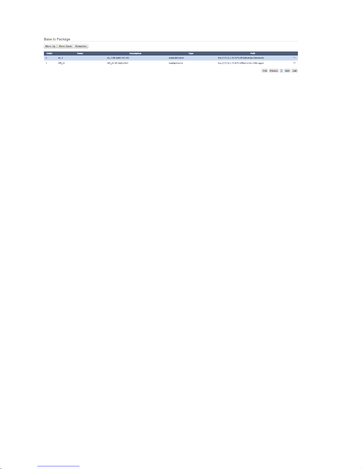
The move up, move down and renumber buttons allow you to change the order of the sources in the virtual source
package. Once applied this virtual source now has both a gpio and audio source and so routing that virtual source to
a virtual destination will attempt to make both a gpio and audio route change underneath. The same process can be
used to edit and manipulate the virtual destinations.
The points tab on the virtual router also supplies a plus icon for manually adding virtual sources and destinations
and minus icons for deleting a virtual source or destination from the router.
Once the router is created, open the routes tab to make and view route changes on the virtual router or use
PathnderClient.
Deeper Tech: Packaging
For those who are interested in what happens under the hood with virtual routers, this section is for you. Every
virtual source or destination is a package. Within that package is a list of pointers to real sources or destinations.
When you make a route change, the system does a number of things. First it attempts to organize the package
according to the IO types of the pointers in both the source and destination package. For example, it will lump all of
the GPIO points together and all of the Audio points together in each package. Then it will try to make one to one
routes based on the order of the routes in the package.
This also means another way you can use these packages is to lump multiple Audio sources and destinations into a
single package. For example, if you were using some sort of immersive sound conguration that required multiple
channels of audio (7.1, 22.2) to be routed at once, you could package all of the sources together into a virtual source
package and all of the destinations together into a virtual destination package. When the virtual route is made,
Pathnder Core PRO will step through each line in the source package and try to apply it to the same line in the
destination package in the order which they exist in the package. If the count in the source and destination packages
does not match, the system will go as far as it can creating the matches. For example, if the source package has
1 source and the destination package has 2 destinations, only the rst destination will get a route. If the source
package has 2 sources and the destination package only has a single destination then only the rst source will get
applied anywhere.
In the same fashion, the state of virtual routes gets updated automatically as base routes in the packages change. If
an audio route changes and the source and/or destination exists in a virtual router, an analysis is done to determine
if the current route states of any of the source packages match what would happen if the source were applied to the
destination. If so, the virtual route is updated to reect that source as the current route. If multiple source packages
match the destination, then the rst one with the most matches is displayed as the currently routed source.
If no source package matches a destination package, then the route may have two other states. One is “None”. This
state means that none of the destination package’s destinations are assigned to anything. The other state is “Other”.
The “Other” source means that some of the destination package’s destinations have some route applied to them but
it does not match up with any of the source packages in the virtual router. This explicitly displays a differentiation
between a destination that is cleared and one that might be in use in some fashion, but not one that the virtual router
5: Routers • 28
can represent given its existing conguration.
© 2017 Telos Alliance - Rev 1.2
Page 38
Chapter 6
Logic Flows
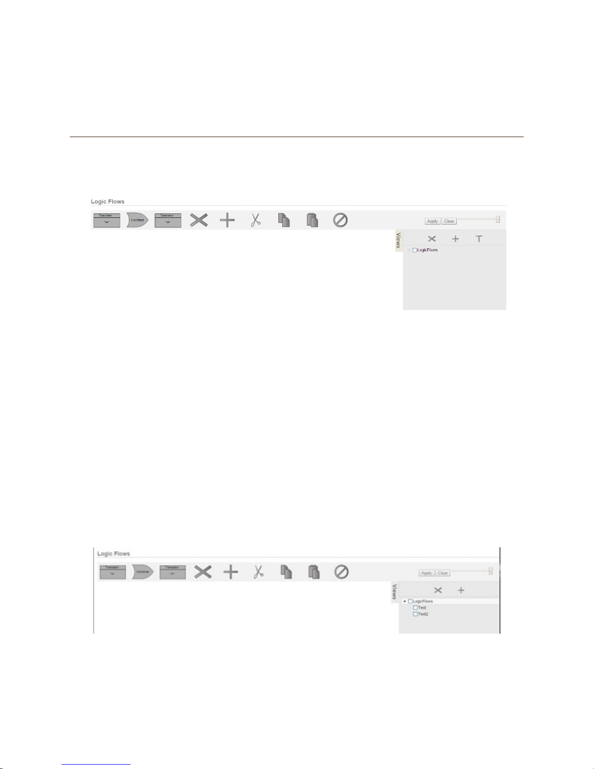
Pathnder Core PRO’s event system is called logic ows, and it enables information visualization, so that you can
see how things work within your system. Clicking on the Logic Flows link in the navigation bar will display the
Logic Flows user interface.
Each logic ow can be thought of as an event. More specically, a ow is a set of property translations. During an
event, we convert an input property value to an output property value.
There are four components that may be used to design a ow:
6: Logic Flows • 29
• StartPoint - A property in the system which is being monitored for changes.
• EndPoint - A property in the system which will be changed by the ow.
• Translator - A list of changes that can be applied to the value of a property.
• Combiner - A way to logically combine multiple states using logical operators such as AND, OR, NOT, etc.
By using these tools, you can build logic visually to accomplish just about any task you want. Let’s look at some
examples.
When you rst look at the Logic Flows Screen you will see a toolbar across the top of the screen and an
organizational panel on the right called Views.
© 2017 Telos Alliance - Rev 1.2
Page 39
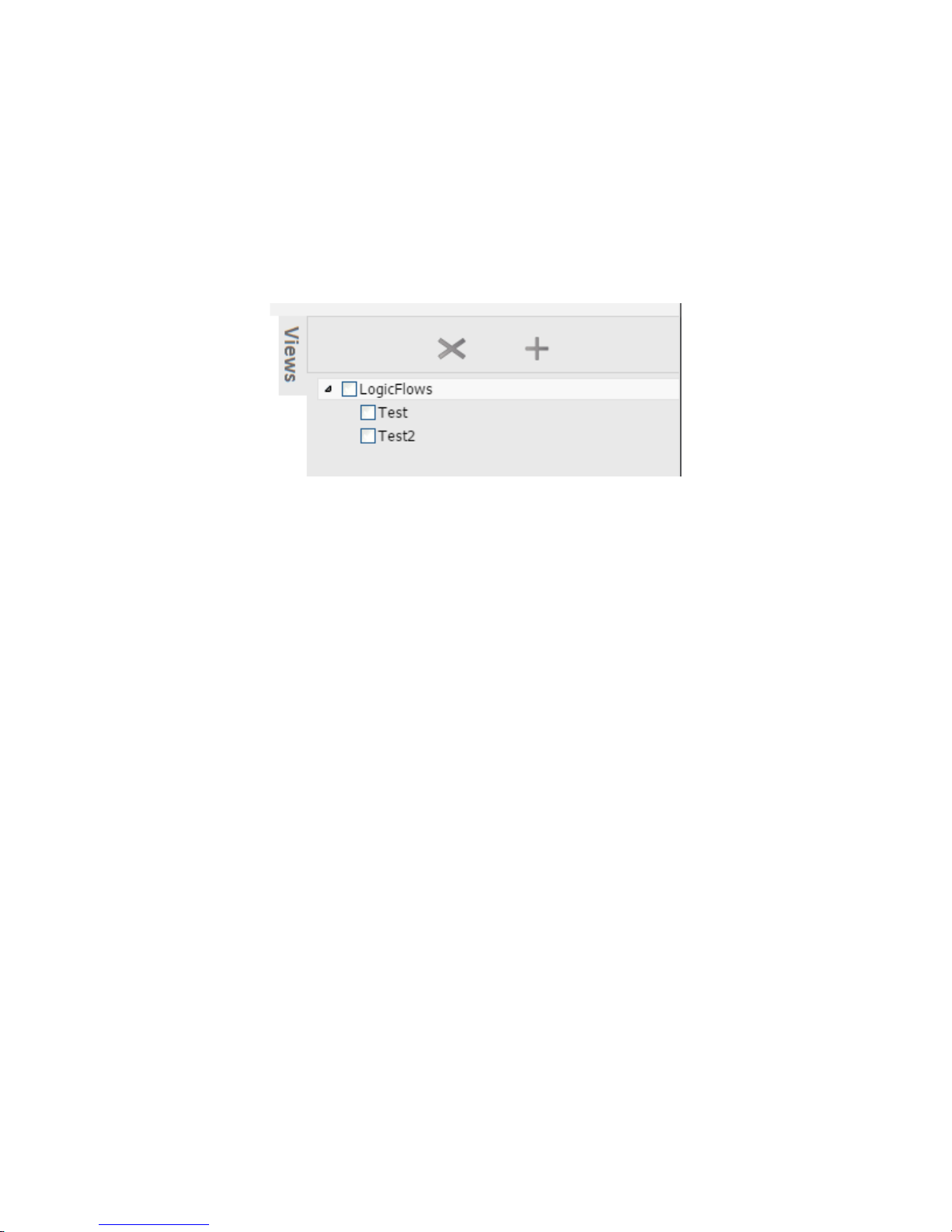
Views
The Views tab may slide in and out by clicking on it. You can think of views like folders in your computer’s le
system. They are organizational containers into which you can place ows. This allows you to keep all of the ows
related to a certain subject in the same place. You can select multiple views to view the ows from multiple views
together in the same screen. In order to create new ows, you have to select a single view since the system has to
know which view to place the new ow into. Like a folder structure, you can nest views as deep as you like. Just
check the parent view and then click the Add (plus) button in the views panel to create a new view.
While you can add ows to the master LogicFlows view, it is not recommended as this is the one view that you
cannot completely delete. It is recommended that you devise a strategy for your view naming and create the
appropriate views underneath Logic Flows to hold your ows. It is also important to note that each view is limited
to displaying 100 ows.
It is also important to note that there will likely be a special view called HardwareMaps. This view is created by
the system and used to manage the mapping of software buttons to hardware controls. This is described in Chapter
19 PanelDesigner, but it is important to understand that the HardwareMaps view is a special view managed by the
system and should not be deleted.
Views can be deleted by selecting the view and clicking the X button in the Views panel (not to be confused with the
x button in the main logic ows toolbar). When you delete a view, the system will ask for conrmation because all
logic ows and descendent views of that view will be deleted as well.
6: Logic Flows • 30
© 2017 Telos Alliance - Rev 1.2
Page 40

Toolbar
The toolbar presents a number of controls. These controls will be enabled or disabled depending on whether it is
currently valid to use that control. For example, the scissors icon (cut) will not be available if you do not have a
ow selected that may be cut.
From left to right the controls on this tool bar are:
• Starting Translator - Allows you to add a translator to the left side of a combiner or to extend the ow’s
start to a new ow.
• Combiner - Allows you to add a combiner
• Ending Translator - Allows you to add a translator to the right side of a combiner or to extend the ow’s
end into a new ow.
• Delete - Allows you to delete a ow or a ow combiner or translator.
• Add - Create a new ow.
• Cut - Cut a ow to the clipboard.
• Copy - Copy a ow to the clipboard.
• Paste - Paste a ow from the clipboard.
• Disable /Enable - Disable or enable a ow or a combiner or translator.
On the Far right side of the tool bar are:
• Apply Button: Applies pending changes to the system
• Clear Button: Clears pending changes and reverts back to the actual state of the system
• Size Slider: Increases of decreases the size of the ow objects in order to display more items on one screen.
6: Logic Flows • 31
© 2017 Telos Alliance - Rev 1.2
Page 41
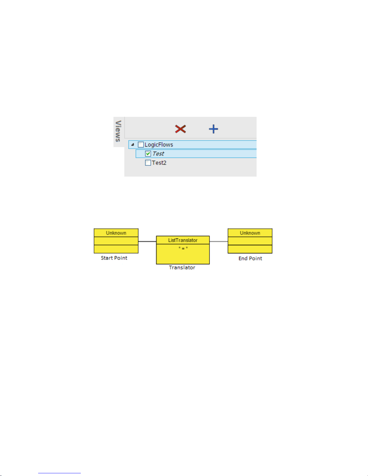
First Flow
Understanding how these tools are to be used will be easier if we create a ow and start explaining the process. First,
create a view and make sure that view is selected. To do this, click the Logic Flows check box in the Views panel
so that it is selected and its checkbox is checked, then click the plus button in the views control panel. The system
will ask for a name for the new view and will create that view underneath the Logic Flows view when you click ok.
At that point click the newly created view so that its checkbox is checked and click the root Logic Flows view to
uncheck its checkbox. Now you should have only your new view selected. In the example below, I created a view
called test.
You will notice that once a single view is selected, the Add button (plus) in the main control panel for Logic Flows
will switch from its disabled grey to blue indicating that you can now use that control to add a new ow.
If you click on the Add button, it will create a new ow consisting of a start point, a translator, and an endpoint.
This ow is in yellow indicating that these are pending changes that have not been submitted to the system yet.
So far, they only live in your local browser. All ows must have at least one start point, one end point, and one
translator. This is the simplest ow you can create. However, we have not yet set parameters to dene what this
ow will do. You can dene the options for each block in this ow by double clicking on the block. However,
double clicking on the translator itself will not do anything until the start point and endpoint are dened. The reason
for this will be explained shortly.
Double click on the start point block. It will turn orange on the rst click to indicate that it is selected. The second
click will then open up the property selector dialog. This dialog is used to select a property in the system that the
new ow will monitor for changes.
6: Logic Flows • 32
© 2017 Telos Alliance - Rev 1.2
Page 42
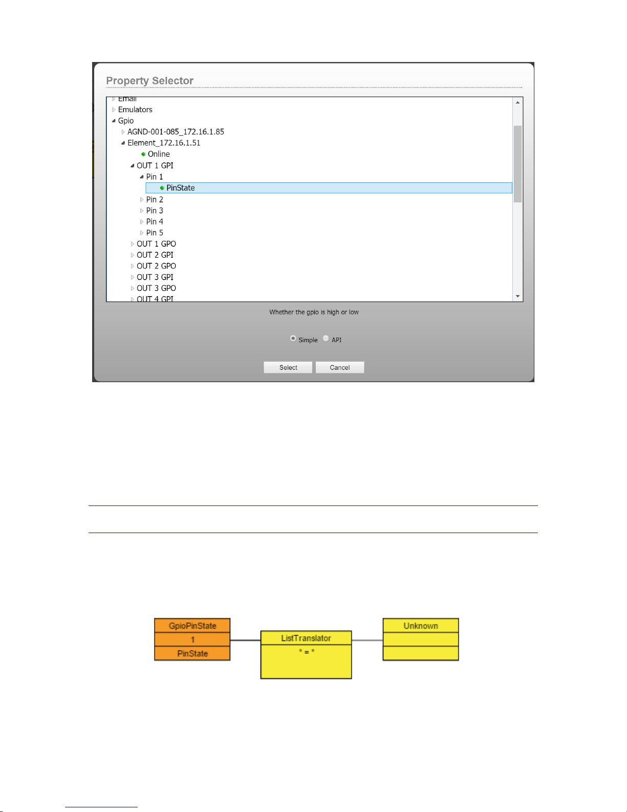
Use the arrows to expand and navigate into the objects in the system until you nd the object and property you want
to select. Properties will have a green dot next to them as opposed to the expansion arrow. You can either select
the property you want to monitor and then click Select or just double click on the property to select it. In this case
we are selecting the PinState property of GPI#1, Pin#1 on the Element at 172.16.1.51. It is useful to notice that as
you select properties in this dialog, a description of the property will usually appear underneath the tree window
providing more detail about the property’s purpose. If you are uncertain about the purpose of a property, selecting
the property can provide you with the information you need to understand its purpose.
Note: The property selector dialog has a simple list and an API list. The API list is only recommended for
advanced users and so will not be discussed until later in the documentation.
Select the start point property by clicking on it and clicking select or alternatively just double clicking on the
property. Again, we are selecting properties which will have the green dot next to it. And in this example we are
selecting the PinState property of a GPI. Once you have selected the start point property, the block will be lled in
with the information you have selected.
6: Logic Flows • 33
© 2017 Telos Alliance - Rev 1.2
Page 43
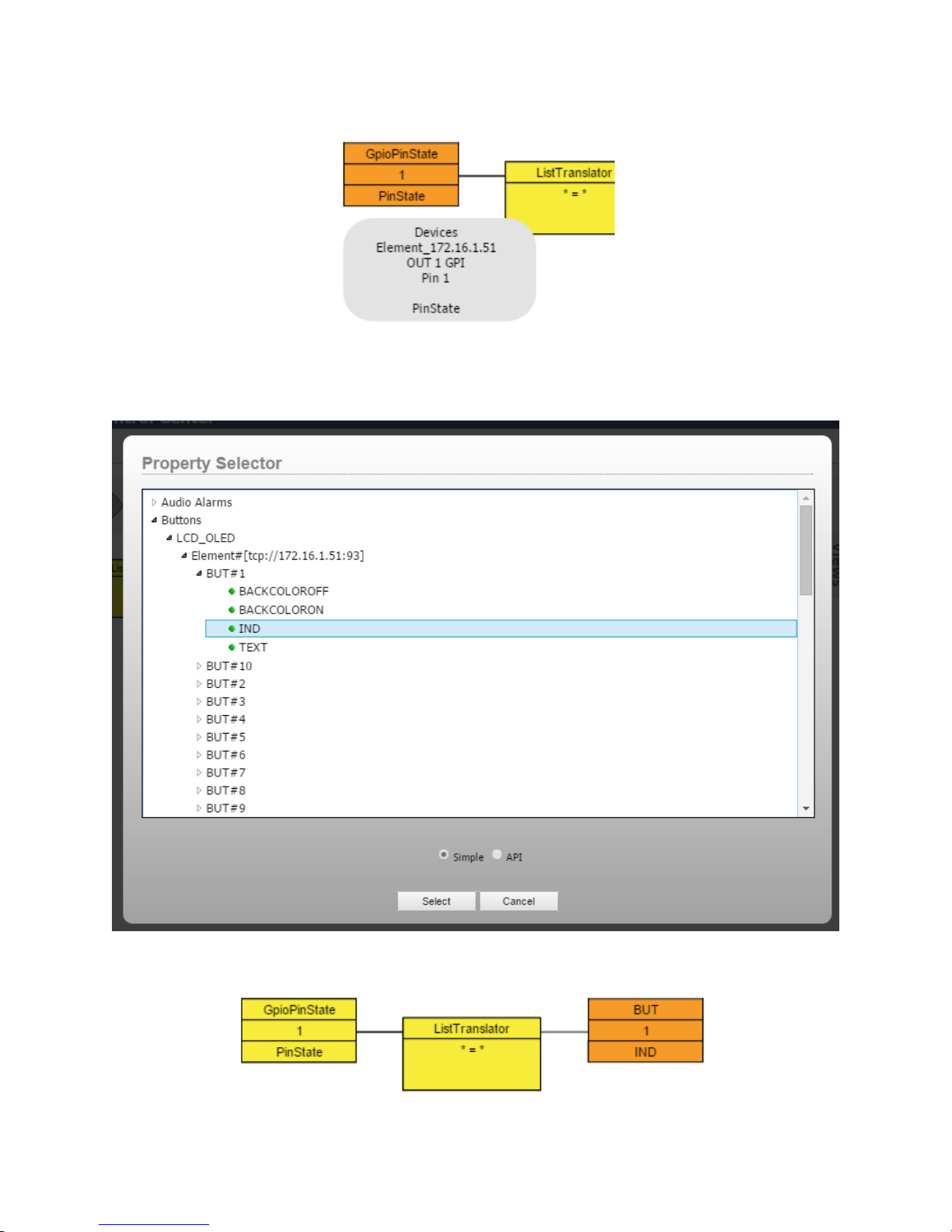
Hovering over the start point that has been assigned a property will also cause a pop-up hover box to appear with
more detailed information about the selected property.
Double click on the ending block and repeat the procedure to select the endpoint or the property we want this ow
to change. In this case, I am going to pick an LCD button, but you could also pick a GPO in order to make the GPO
state follow the GPI state.
At this point, the ow would look something like:
6: Logic Flows • 34
© 2017 Telos Alliance - Rev 1.2
Page 44
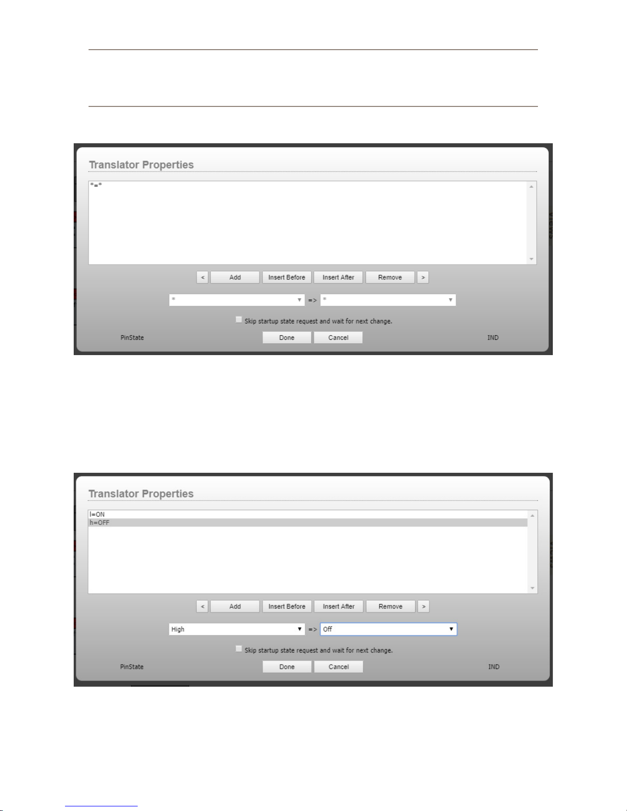
Note: You may nd that the list of available properties dif fers depending on whether you are editing a
start or an end point. This is because the system is intelligent enough to know if a property is read only
or read write or write only. Properties that are read only may not be used as an end point (something you
want to change). So the system will only display properties that make sense for the type of block you are
editing.
Once you have a start and an endpoint, you can edit the translation table by double clicking on the ListTranslator block.
This dialog allows you to enter a list of translations which you want to take place. Select the Top translation point
(*=*), this will enable the drop down boxes below. You will notice that the drop down on the left side now has Low
and High as options, and the one on the right has a list of indicator states such as off, on, ash, etc. So select Low
in the left box and On in the Right box. The translation point above will update with your changes. Now click the
Add button to add another translation to the list.
For this one select high in the Left and Off in the Right. It should look something like:
What we have just dened is that if the start point (GPI) is low, then we are going to set the LCD Button indicator
on the button to On. If the GPI is high, then we are going to set the LCD button indicator to Off. We are essentially
6: Logic Flows • 35
dening a list of rules as to what the endpoint should be depending on what the start point currently is.
© 2017 Telos Alliance - Rev 1.2
Page 45
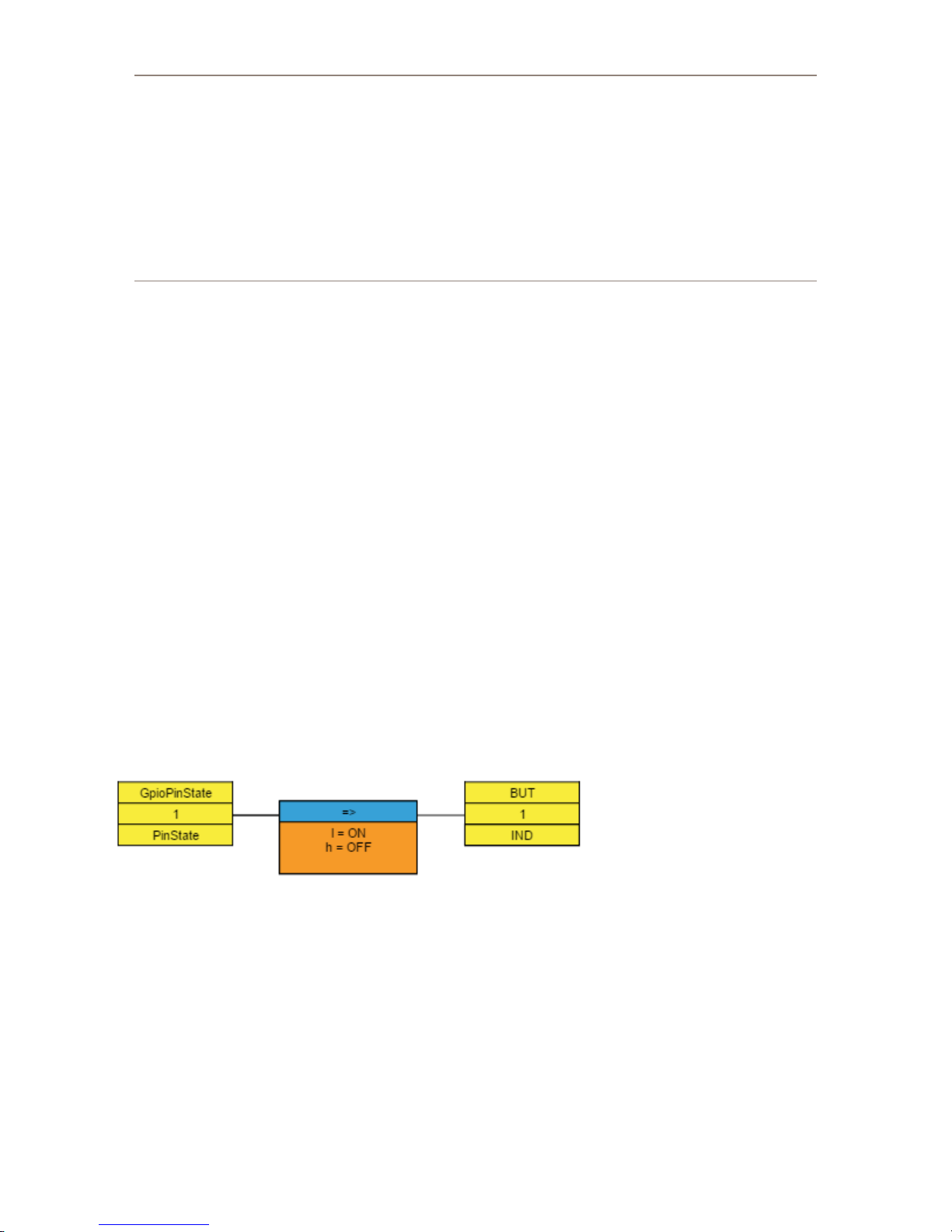
Note on the asterisk: The asterisk is a special catchall item that can be considered to be any. For
example, we could have made the second entry in this translation list *=OFF. Since the list is analyzed
in order, this would mean that if the GPI is low, then the indicator should be turned ON. If the GPI is
anything else other than low than turn the indictor OFF. In this case using * or explicitly dening the high
are equivalent because the GPI only has two possible states. Where the * comes in useful is in situations
where there are a bunch of options on the start point side. For example, if the star t point was the current
source routed to a destination, we could build the translation such that if a specic source is selected the
indicator would be on, and then use the * to say if there is any other source routed, turn it off. Order is
important. If you were to move *=Off to the top of the list, then the indicator would always be off because
the rst item in the list says if anything then of f, and the system would never analyze any of the other items
in the list. Generally a * should almost always appear at the end of a list of translations as a catchall. If
there is a * on the right hand side of the translation it means to pass the value from the left on unchanged.
So *=* would pass anything from the start point to the end point (or next step in the ow) unchanged.
For those of you familiar with any programming languages, this list works very much like a select case or switch
statement. When the start point property changes, the value is analyzed in order through this list until a match is
found and then the correct value is applied to the endpoint or next step in the ow. If no match is found, then the
endpoint is not changed.
The reason you were unable to edit the translation block until both the start and end point properties were chosen
is because the system tries to help you with the list of possible options depending on the property selected. For
example, in this case you got Low and High on the left, and a list of indicator states on the right. If the start point
had been the CurrentSource property of a destination, then this drop down would present a list of available router
sources.
The other buttons on the translation list screen can be used to move translation denitions up and down in the list,
insert new ones, and remove them.
The “skip startup state change and wait for next change” checkbox also requires some explanation. By default (this
checkbox unchecked) when a ow is applied to the system or the system starts up, the ow asks for the current state
of the start point and then applies the correct result to the end point. Occasionally you may not want this to happen
when the ow is rst created and/or loaded at startup but would rather wait for the next change in the system that
would cause the ow to execute. Use this checkbox for these cases.
Once you are done click Done. The ow will now look something like:
This ow is not active yet. The yellow states are showing us that this ow is being designed but that the changes
have not been committed to Pathnder Core PRO yet. They only exist as objects in your browser. You should also
see the Apply button ashing to indicate that changes are pending.
6: Logic Flows • 36
© 2017 Telos Alliance - Rev 1.2
Page 46
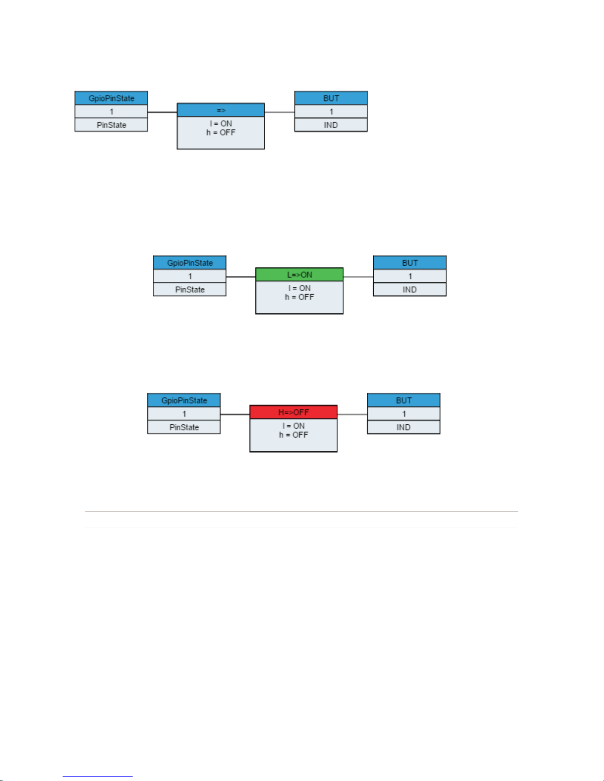
Click Apply to commit the changes to Pathnder Core PRO. The ow will now change colors to indicate that it is a
live and active ow:
Dynamic Data
The ow diagram does not just show the design of the logic ows in your system. It also shows the live up to the
second state of each of the ows. Using the ow example created above, if we trip the source GPI to low, we will
see the diagram change to:
And if we switch it to High, it will change to:
Within the top of the translation box, we see the currently active translation state in text and a color change
depending on that state.
Note: These colors come from a le that may be edited in an advanced web page if necessary.
In this way, the system also dynamically displays the state of the ows for easier monitoring and troubleshooting.
6: Logic Flows • 37
© 2017 Telos Alliance - Rev 1.2
Page 47
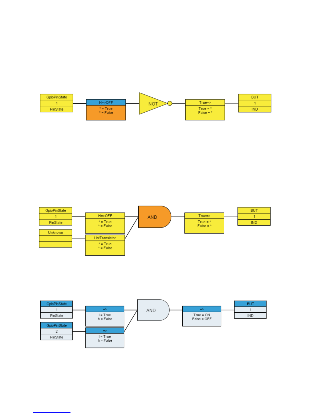
Combiners and the second flow
Translation points are one to one only. In other words, we are translating one value from a property to another value
on another property. Combiners on the other hand, allow us to pass values to multiple endpoints and to make logical
decisions based on more than one start point. In order to add a combiner, select a translator in an existing ow by
clicking on the translation box in the ow. Once selected the combiner tool in the tool bar will become enabled.
Clicking the combiner will insert a combiner into the ow. If you do this on the ow we just created in the example
above, it will look like:
You can change the combiner type by double-clicking on it. This will rotate through a number of different combiner
types. However, each combiner has a maximum and minimum number of inputs that are required to use them.
Only combiners that t the number of inputs entering the combiner will be available. If you double click on the
NOT combiner you will notice that it switches from NOT to PassThru and back to NOT. That is because the only
combiners that are available with a single input are NOT and PassThru. If you click on the Combiner to select it,
you will notice that both the left and right translator tools become available. Clicking on either of these will either
add a translator to the input side of the combiner or the output side of the combiner. If you add a second input, you
will notice that the combiner will now rotate through more types because there are many more logical types that
work with two inputs.
In this case, since the combiner is a logic gate, the translation types are automatically switched to True/False
entering and exiting the combiner. By assigning a second GPI pin to the second start point, we can change this
event so that two buttons must be held simultaneously in order for the end point change to happen. Edit the various
translation lists as described above, and then when complete click apply and you should end up with something like:
Essentially this ow will light the indicator light on the button only if both GPI 1 and 2 are low. This does not
look very useful, but if we were to change the endpoint to be a route destination, it becomes more interesting.
6: Logic Flows • 38
To do this, double click on the endpoint box and instead of a GPIO, expand the routers section and select the
CurrentSourcePath property of one of the router destinations.
© 2017 Telos Alliance - Rev 1.2
Page 48
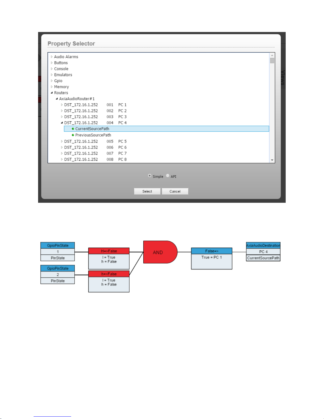
Then edit the translation which is after the combiner and change the translation so that True= one of the sources
from the sources that will be in the right hand side drop down of the translation dialog. Remove the false translation
because we do not want to do anything if the buttons are released and you end up with:
This essentially means a user has to hold two GPIO buttons down simultaneously, and then the PC4 destination will
get source PC 1 routed to it. This is a common scenario where we don’t want an accidentally bumped button to
change the air chain routing so we require two buttons to be held together.
6: Logic Flows • 39
© 2017 Telos Alliance - Rev 1.2
Page 49
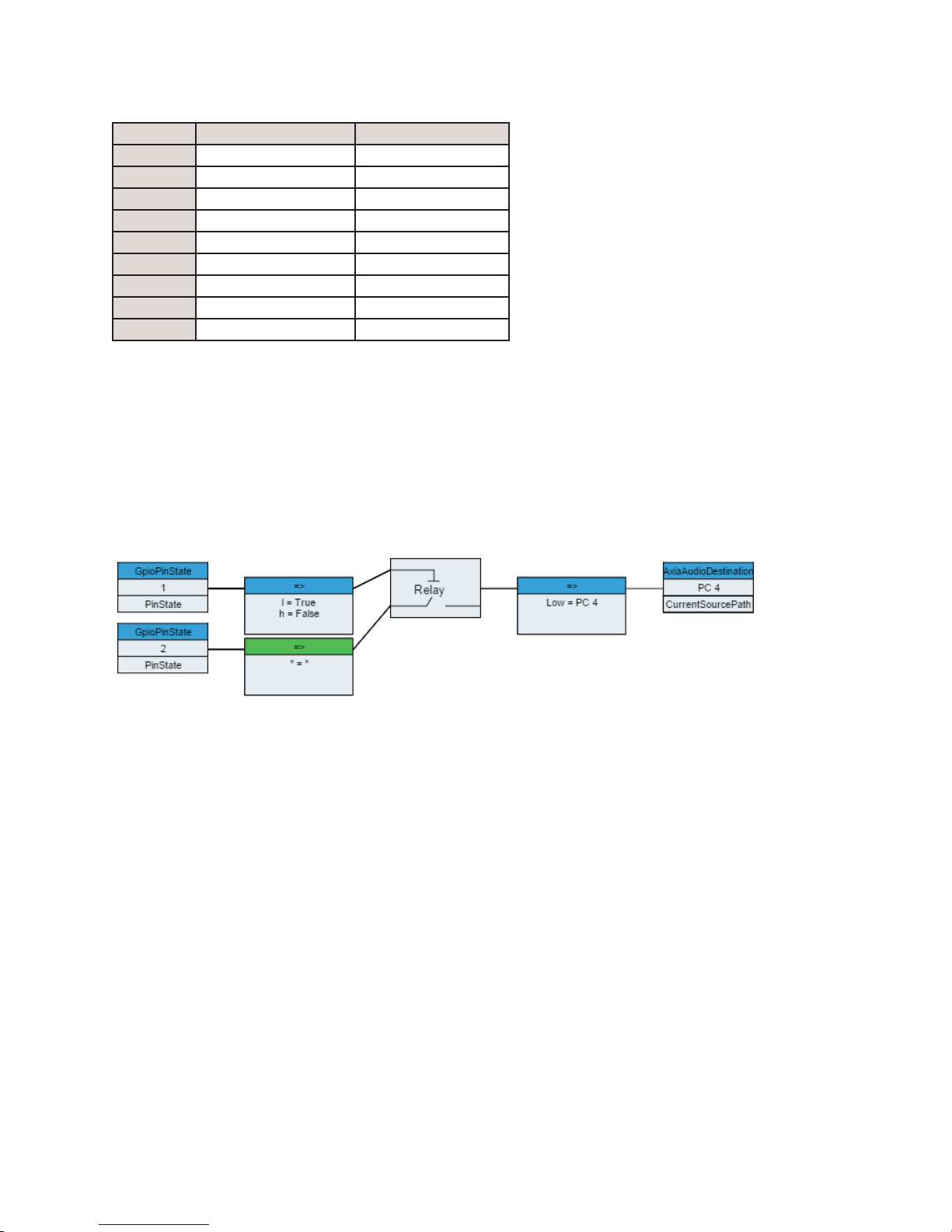
The available combiner types are shown in this chart:
Type Minimum Inputs Maximum Inputs
AND 2 Any
OR 2 Any
NAND 2 Any
NOR 2 Any
XOR 2 Any
XNOR 2 Any
NOT 1 1
RELAY 2 2
PASSTHRU 1 1
The RELAY and PASSTHRU combiners do require a bit more explanation. The PASSTHRU combiner only allows
1 input and passes the value from the start point translation to as many output translators as you like. This allows
you to make multiple output properties change based on a single input property. The relay combiner allows you to
dene one start point property that will translate to a true or false. If that evaluates to true then the value from the
second start point is passed through the combination to any translations on the output of the combiner.
The diagram within the combination displays which start point translation is acting as the trigger and which is acting
as the PASSTHRU.
6: Logic Flows • 40
This will actually achieve the same functionality as our previous example, but in a different way. GPI 1 must be low
in order for changes taking place on GPI 2 to pass thru. If it is low then changes from GPI 2 will be passed to the
output translation which converts the Low to a route change.
© 2017 Telos Alliance - Rev 1.2
Page 50
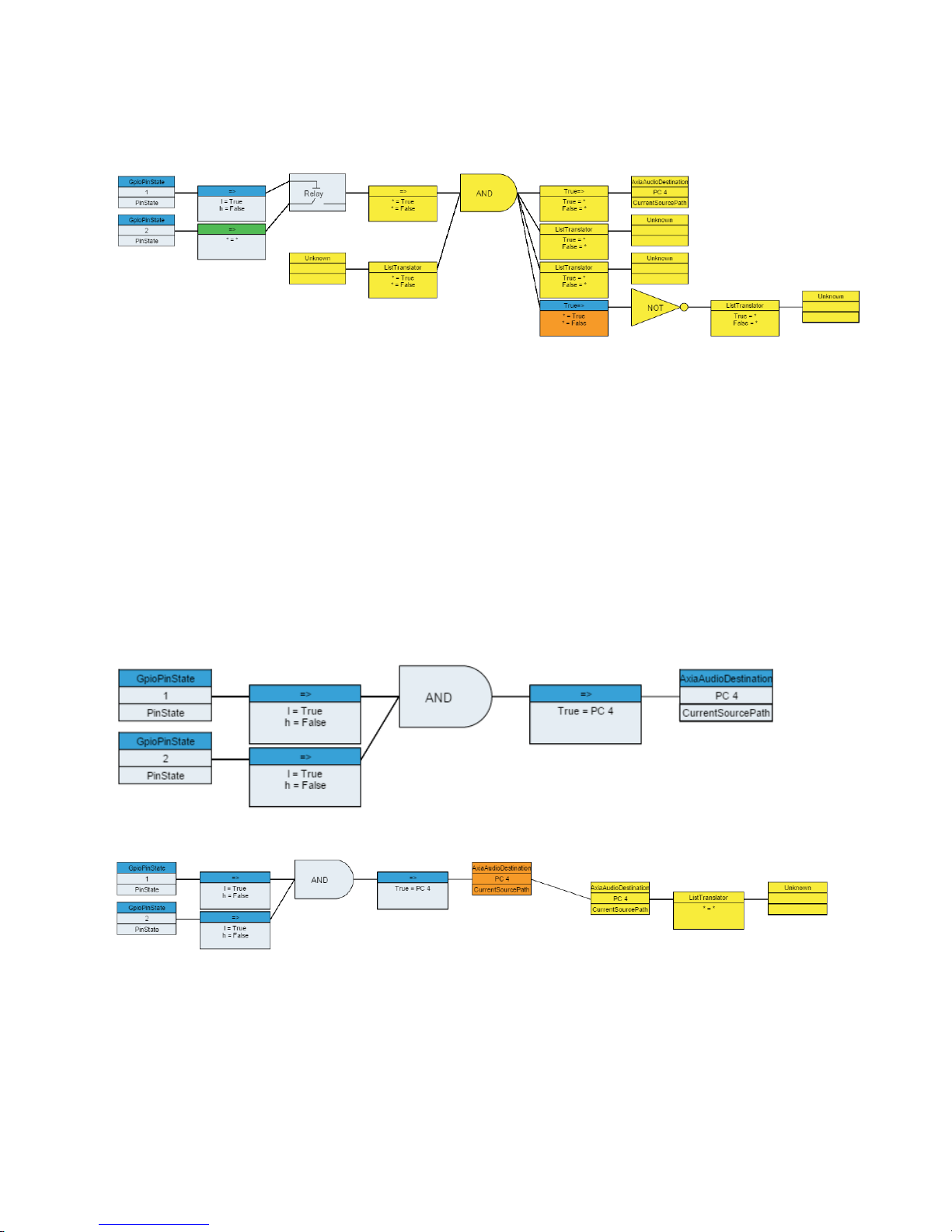
Going Crazy
By adding combiners and translators you can make any individual ow as deep as you need it to be.
This example is not created to do anything specic, it is just shown to illustrate that you can theoretically continue to
add translations and combinations as needed to get the particular logical job done. Translators and combiners must
alternate. You cannot have a combiner next to a combiner or a translator next to a translator, but the user interface
helps with that by only enabling the controls you can use depending on which logic block you currently have
selected.
Extending Flows
If you select the endpoint of a ow, you will notice that the right translator control in the control panel is available
(not disabled). This is what is referred to as extending a ow. You can create a second ow whose start point is the
same as the endpoint of the previous ow.
If we go back to this example ow:
Click on the endpoint and then click on the right translator control, you will get:
In this case the second ow is joined to the rst because the start and end properties are the same. Likewise, if we
had added a second ow using the + button and then set the start point to the PC4 destination’s CurrentSourcePath,
after we applied the change, the system would detect that the ows should be joined and join them. In this example
we could now set the indicator of a button at the endpoint of the second ow:
6: Logic Flows • 41
© 2017 Telos Alliance - Rev 1.2
Page 51
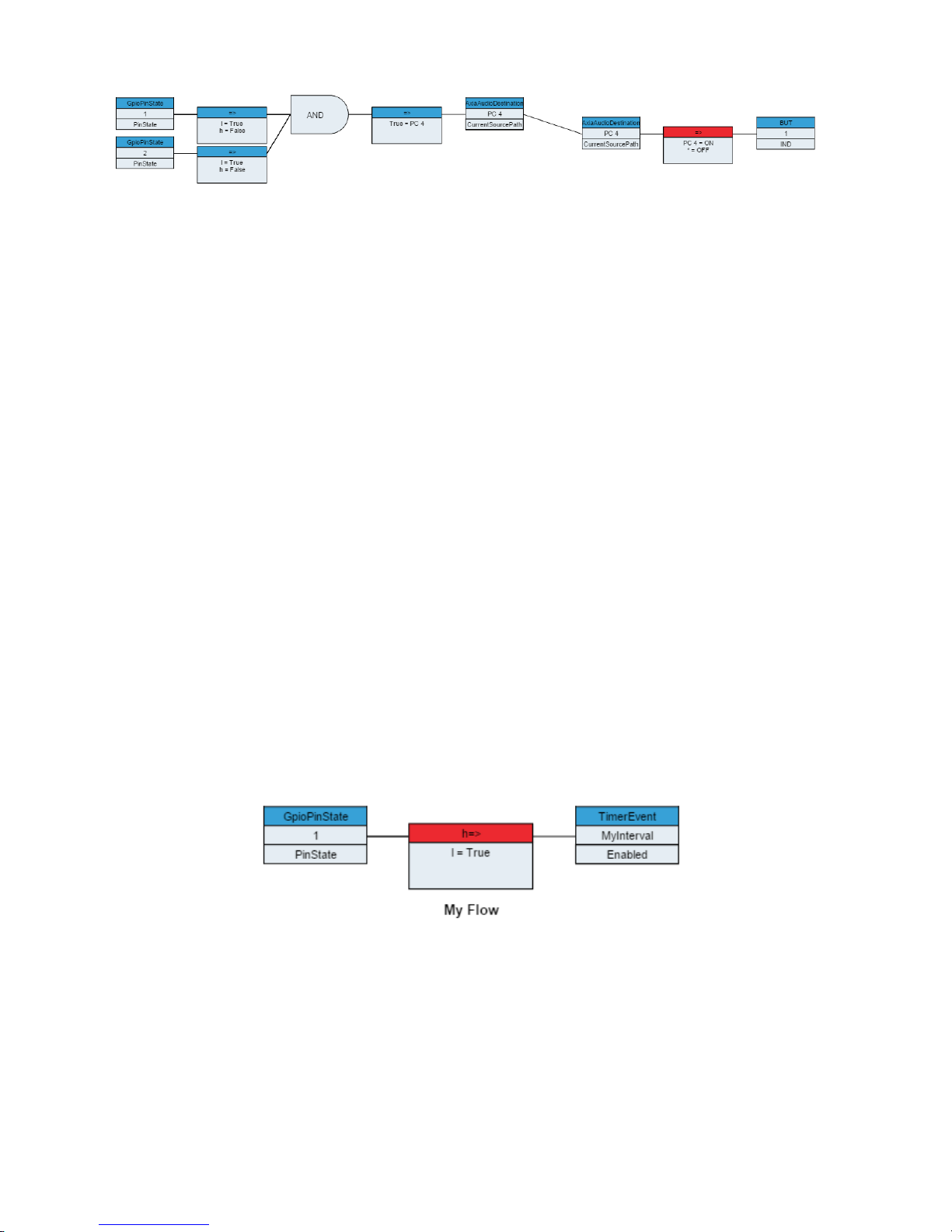
What we have designed is a ow where if you hold GPI buttons 1 and 2 down, PC4 source will be routed to PC4
destination. And if PC 4 source is routed to PC4 destination then LCD button 1’s indicator will be turned on. If
anything else is routed to that destination then the Indicator will be off.
The system is intelligent enough to recognize when ows should be joined into a single logical entity.
Cut, Copy, and Paste
Cut, copy, and paste are standard tools, and require little explanation. You can select a ow by clicking in the
area surrounding a ow. At that point the cut and copy icons will be available. Cut will remove the ow from the
view and place it on the clipboard and copy will just make a copy of it on the clipboard. Once a ow exists on the
clipboard it can be pasted back into the view or into any other view.
The system does make some assumptions regarding pasting. If you copy a ow and paste it back into the same view,
the system assumes you are trying to duplicate the functionality with a new set of endpoints. So it will actually clear
the outer start and endpoints of the pasted ow so you can select new ones.
It is important to reiterate that none of the changes involved in a cut/copy/paste operation ever become a reality on
the system until you click the Apply button and that clicking the cancel button will return to the last known applied
state.
6: Logic Flows • 42
Flow Titling
Each ow can be assigned a title. If you double click in the whitespace surrounding a ow, the system will ask
you for a title for the ow. Then click apply to apply the title. Flows that have titles will display the titling text
underneath the ow.
Titling is a very important habit to form as it makes it much easier to glance at a Logic Flow view and understand
the states of the ows and which ows are performing which functions. Additionally, it is useful as an
organizational tool as ows with titles will be displayed alphabetically within the view. Otherwise the ow order
within the view is somewhat arbitrary.
© 2017 Telos Alliance - Rev 1.2
Page 52
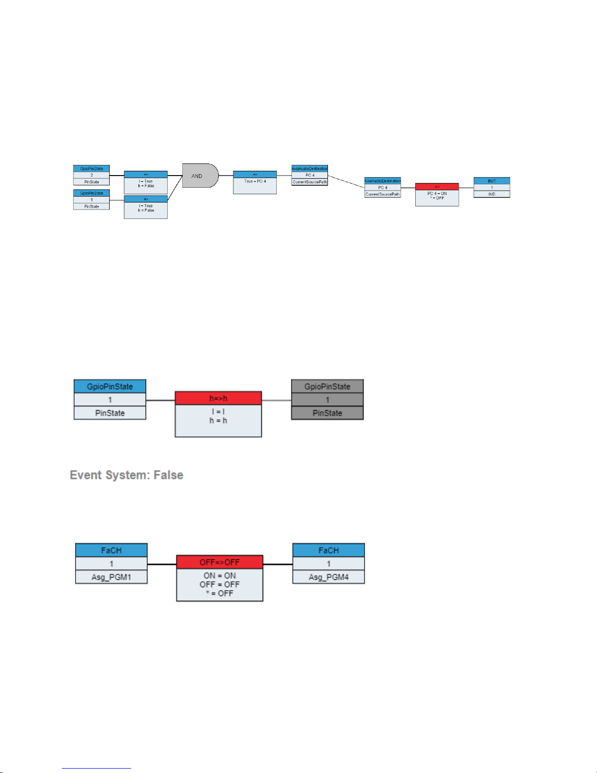
Disabling/Enabling
Translators, Combiners, and entire ows may be enabled or disabled. Select the translator, combiner, or entire ow
(by clicking in the whitespace within the ow), and then use the disable/enable button on the control panel. This
change is the only one that takes place immediately within Pathnder Core PRO logic ows without the need to
click apply. The object will become greyed out and that particular object will no longer function, stopping the logic
ow at that point. For example:
If you trigger the GPIs, their states will change within the attached translators, but the endpoint in the rst half of the
ow will not change because the combiner is disabled. This is a useful tool if you are testing logic up to a point but
do not want the endpoint (which might be an air chain change) to change. It is also useful if you want to temporarily
disable a ow during testing or troubleshooting.
Cluster Disabling
If your system is clustered and you are viewing logic ows on the secondary system you may see a darker gray form
of disabling.
6: Logic Flows • 43
Also with clustering the upper right corner will show and event system state.
In this case you are being shown that the nal output will not actually execute on this server because the other server
is currently in control of the event system. On that server, you will see:
© 2017 Telos Alliance - Rev 1.2
Page 53
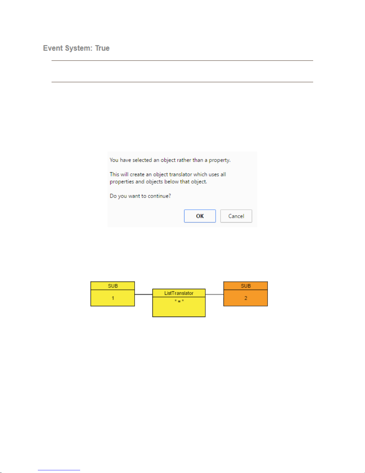
And in the right corner:
Note: The event system is never actually off in Pathnder Core PRO. When a logic ow needs to make
a change to an endpoint, it r st checks to see if it has the lowest IP address of the currently active and
online ser vers in the cluster. If so then it executes the action. If not, then it does not.
The Event System True or False will be hidden on systems that are not in a cluster because in that case the logic ow
endpoints will not be disabled by the clustering system.
Object Translators
You may notice that when editing the start or end point of a ow, if you select an object in the property selection tree
(arrow icon) instead of a property (green dot icon), you will get a warning message that looks like:
Object translations are a slightly more advanced subject and should be used with caution (hence the warning), but
they can also be extremely powerful. Object translations will most likely be used in situations where you want to
mirror several different property states across a couple of objects. We could create a translator logic ow where the
start point is a VMIX sub mixer on Engine 1 and the Endpoint is a different VMIX sub mixer on a different engine.
You will notice that this translator looks slightly different in that the start and endpoints only have two pieces of
information rather than the usual 3. If we do not alter the translation pattern from the default *=*, this will mean
that every change to every property of every sub object under the sub mixer 1 will get mirrored to the equivalent
object and property under sub mixer 2. So if sub mixer 1, channel 1 gets turned on, then sub mixer 2, channel 1 will
also be turned on. If sub mixer 1, channel 3 has its “TimeDown” property changed, then sub mixer 2, channel 3 will
also get its “TimeDown” property changed. In this way we can mirror settings of an object.
6: Logic Flows • 44
© 2017 Telos Alliance - Rev 1.2
Page 54
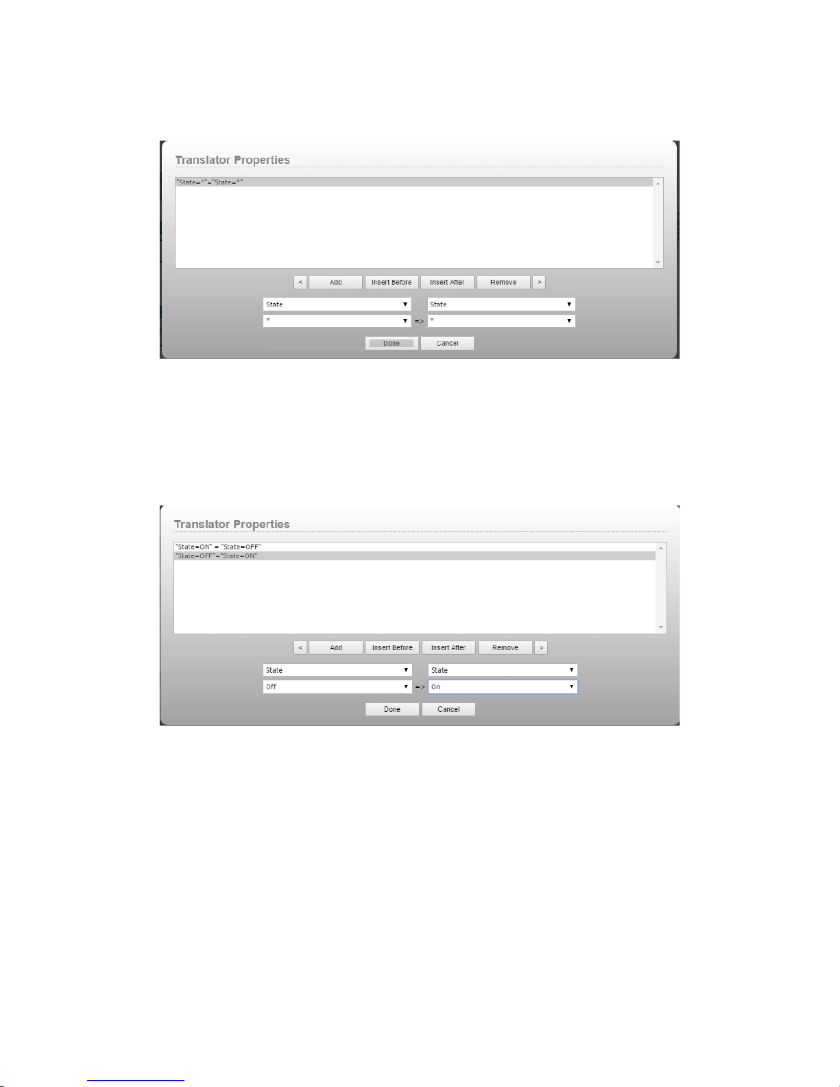
If you edit the translation list, you will notice that some additional elds appear when an object translation is
selected. These additional drop downs allow us to specify properties of the selected object as well as values. For
example, we could change the translation pattern from *=* to:
In this case, we are specifying that we only want this translation to operate on State properties. If sub mixer 1,
channel 4’s state property gets turned on so would sub mixer 2, channel 4’s state property. Other properties would
not be affected.
Or, we could apply values such as:
This allows us to invert the states on the second sub mixer. Now when sub mixer 1, channel 5’s state property gets
turned on, sub mixer 2 channel 5’s state property gets turned off and vice versa.
Object translation is extremely powerful in situations where you want to match a bunch of properties across two
similar objects.
6: Logic Flows • 45
© 2017 Telos Alliance - Rev 1.2
Page 55
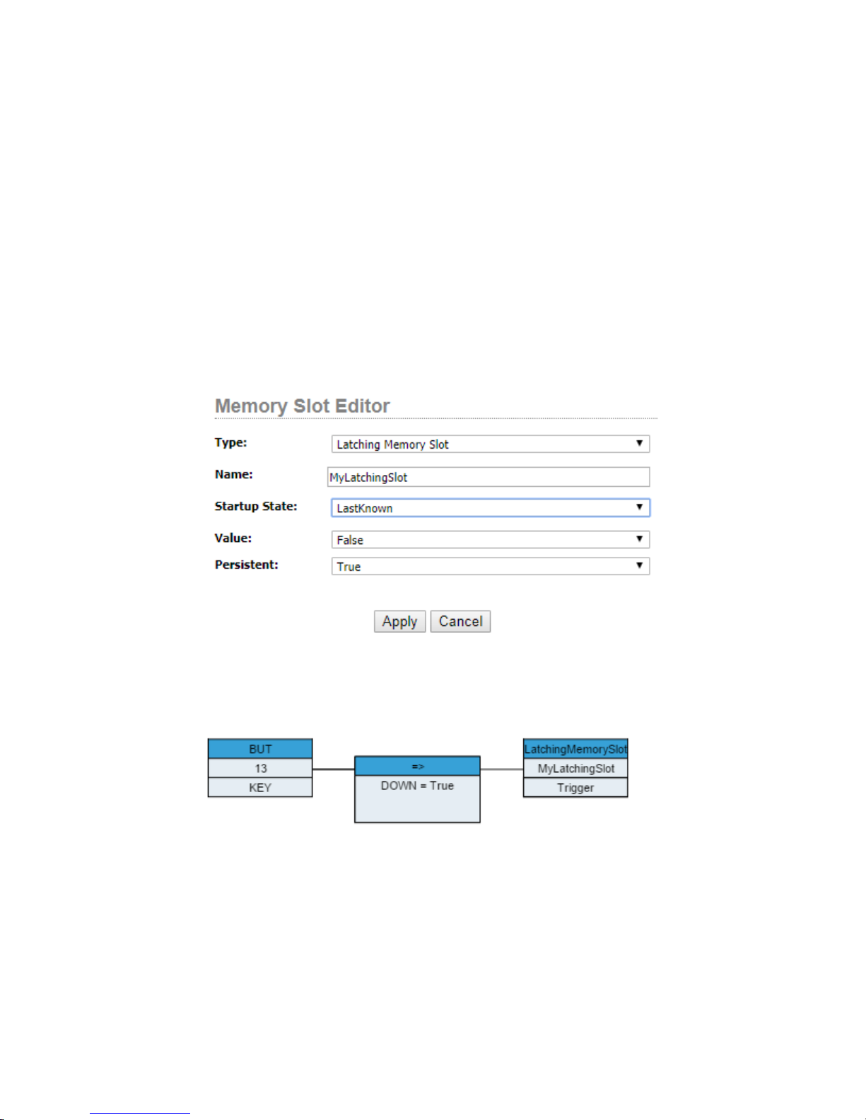
Latching
It is fairly common to need a button within the system to function in a latching fashion where each press of the
button will switch something back and forth. Using the kind of logic shown above to try and accomplish this
can get complicated because the state becomes a condition which is also an action. This leads to interesting and
convoluted loops trying to solve what on the surface appears to be a simple problem. As a result, we have crafted
a much simpler way to do latching in Pathnder Core PRO. That is the latching memory slot. To learn more, see
Chapter 7 Memory Slots. However, since this can be a common logical conundrum that many novice users attempt
to solve with logic ows in strange and frustrating ways, we wanted to specify the correct way to accomplish this.
While basic memory slots can be created using the Logic Flows property tree as a shortcut, there are additional types
of memory slots that can only be created from the memory slots page. These are outlined in more detail in Chapter
7. However, in order to create latching functionality, go to the memory slots link in the Navigation Bar and add a
new memory slot using the plus icon. In the dialog that appears, switch the memory slot type to “Latching Memory
Slot”. Provide a name for the slot and click Apply to create the slot.
6: Logic Flows • 46
The Latching memory slot is a special type of slot that can only have a value of true or false. It also has a write only
property called trigger. For example, in logic ows we could now add a ow such that whenever a button on the
element is pressed the translator sets the trigger property to true.
The trigger property is write only. It cannot be read. And whenever you apply a true value to it, it automatically
switches the SlotValue property of the memory slot from true or false to the opposite state. This simple logic ow
will cause the latching memory slot to switch its value back and forth every time the button 13 is pressed.
© 2017 Telos Alliance - Rev 1.2
Page 56
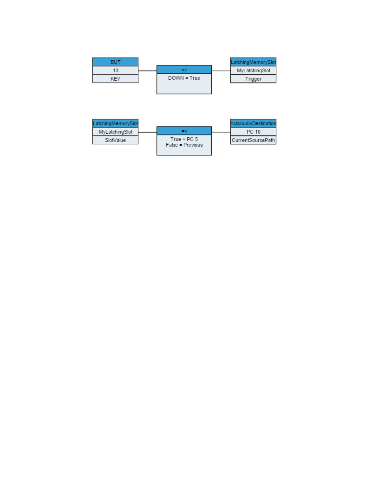
Next, we create a second logic ow that denes what we want to happen depending on whether the Latching
memory slot is true or false. For example:
Now the button will cause the latching memory slot to switch back and forth between true and false and if the slot’s
value is true source PC 5 will be routed to Destination PC 10. If the slot value is False then whatever previous
source will be routed back to Destination PC 10.
6: Logic Flows • 47
© 2017 Telos Alliance - Rev 1.2
Page 57
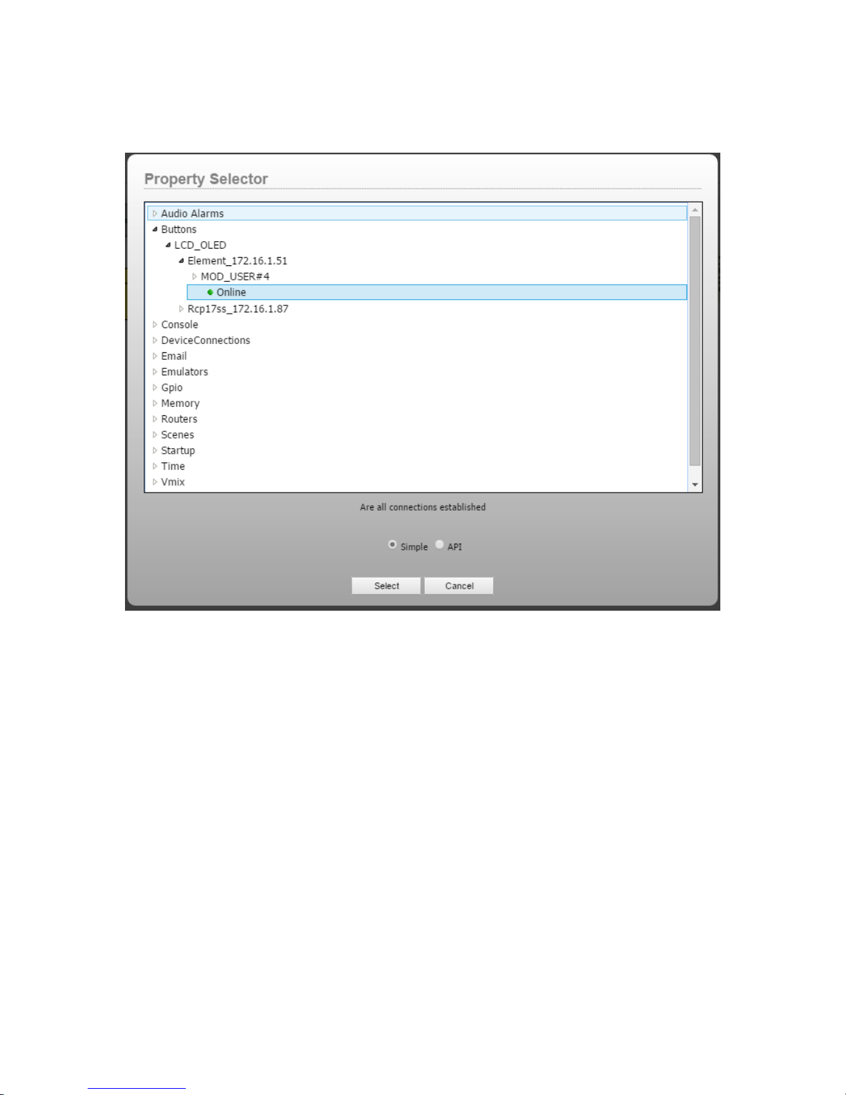
Property List Types: Simple versus API
When editing a start point or endpoint, the property selection dialog has two modes; Simple and API.
6: Logic Flows • 48
The simple tree is what most users should use. It is designed to present the most commonly used objects and
properties organized for quick access. Occasionally there may be a job that requires reaching beyond the normal.
Selecting the API tree will present a much wider array of objects and properties.
Pathnder Core PRO has an advanced protocol called SapV2. In reality it extends beyond most typical protocols
and reaches the level of an API (application programming interface). It allows virtually complete control over the
system. This API is not just a control protocol; it is the protocol which is used for all internal messaging between
services within the system. If you want to learn more about this API, see the SapV2 appendix. In order for this
API to do its job successfully, almost every property and object must be available. The API section of the property
selection dialog exposes the object and property tree available via that API.
© 2017 Telos Alliance - Rev 1.2
Page 58
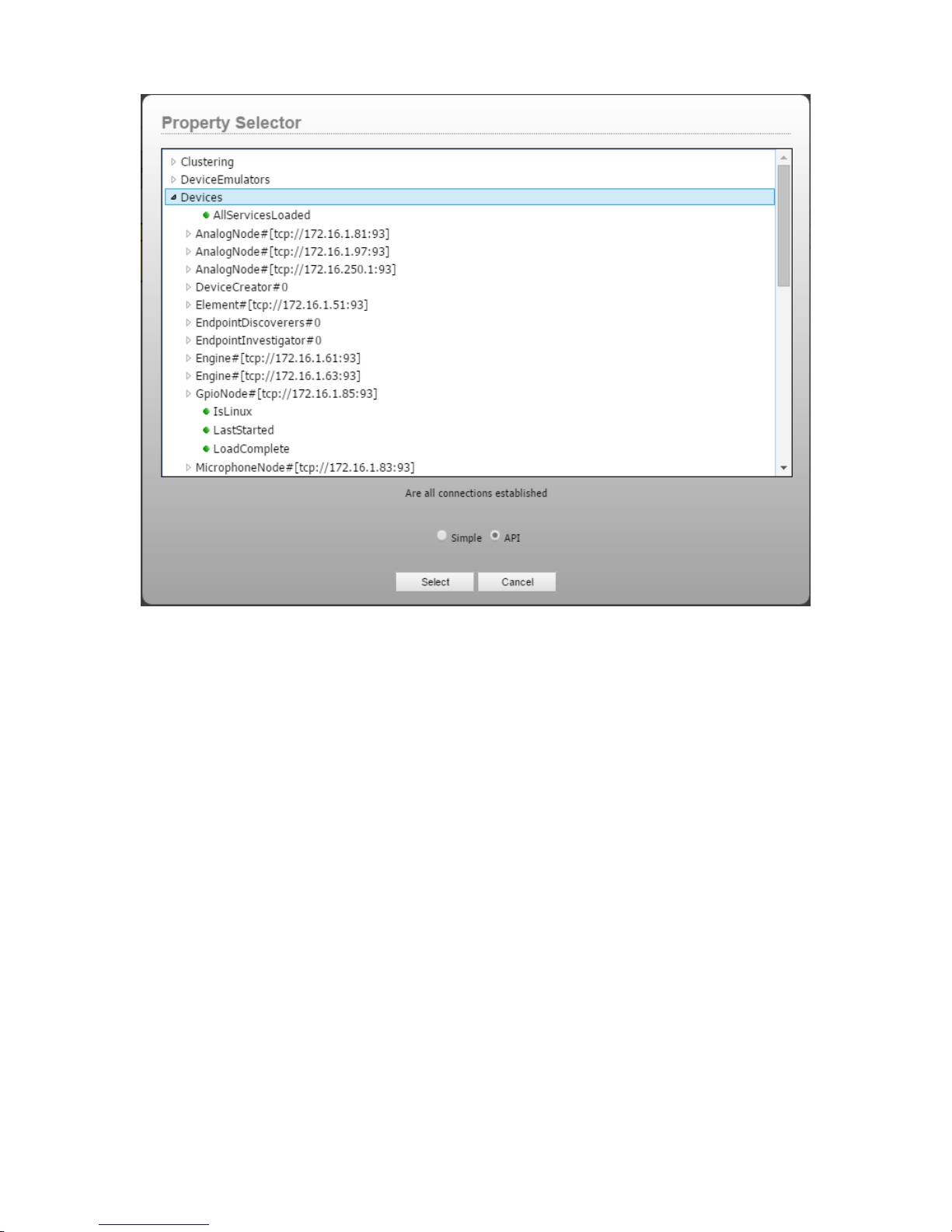
6: Logic Flows • 49
Simple Tree Commonly Used Properties
Providing a list of every object and property in the system is beyond the scope of this documentation. One of the
reasons we provide the description within the property selection dialog is to make the software self-documenting.
However, it is useful to describe some of the more commonly used properties here if for no other reason than to
generate ideas for how to use ows within your environment. This list is not inclusive. Spend some time browsing
the tree and examining the various available properties and their descriptions. And as always, our support staff
stands ready to assist. Remember that due to the read/write nature of some of the properties, they may only appear
and be available for use with a start point or an end point.
• Audio Alarms
» AlarmState: Once an audio alarm has been congured, this property exhibits the current state of the
alarm. It can be Unknown, AudioPresent, AudioSilent, or Clipping. Logical decisions can be made
when this state changes.
» LvlState: When a silence alarm is congured, Pathnder Core PRO requests updates whenever the
threshold value is passed for more than 250ms. This property carries the current state regardless of
the current alarm countdown.
© 2017 Telos Alliance - Rev 1.2
Page 59

• Buttons
» BackColorOn: Used to set the backcolor value when the button is on.
» BackColorOff: Used to set the backcolor value when the button if off.
» Ind: Used to set the indicator of the button on, off, or in a variety of ash states.
» Text: Used to set the Text value of a button.
» Key: This property will be UP or DOWN depending on whether the button is pressed or released.
• Console
» ShowProfId: The id of the show prole loaded on the console. This can also be used to change the
» ShowProfName: The name of the show prole loaded on the console.
» Asg_PGM1-4: Used to set or determine whether a specic console fader is assigned to any of the 4
currently loaded show prole.
program busses.
» Asg_Prev: Used to set or determine whether a specic console fader is assigned to the preview buss.
» Fader_Gain: Used to change the gain of a fader.
» MUTE_State: Used to set or determine if the mute state on a fader is engaged.
» OFF_But: Whether the Off button on a fader is up or down.
» ON_But: Whether the On button on a fader is up or down.
» ON_State: Used to set or determine if a console fader is on or off.
» src_lwch: Carries the Livewire channel number loaded to a fader.
» talkback: Used to engage or sense the engagement of the talkback button on a fader.
» tt_cr: Used to engage or sense the engagement of the talk to control room button.
» tt_st: Used to engage or sense the engagement of the talk to studio button.
» tt_prev: Used to engage or sense the engagement of the talk to preview button.
» IND: Used to change the indicator state of user denable buttons on the console.
6: Logic Flows • 50
» KEY: Used to sense the key state of certain user denable buttons on the console.
© 2017 Telos Alliance - Rev 1.2
Page 60

• DeviceConnections
» Connected: This property can be used to sense and react to connection problems with any of the
Axia devices.
» Online: This property senses whether a device is responding to commands.
• Email
» Body: Used to change the body text of an email message.
» Subject: Used to change the subject of an email message.
» Send: Used to send a predened email message.
• Emulators
» Triggered: Used to determine when a Generic emulator’s watcher detects a dened input value.
» ToSend: Used to send data out a generic emulator port.
• Gpio
» PinState: Used to change or sense changes on a GPIO pin.
• Memory
» SlotValue: Used to sense changes or change the value of a memory slot.
» Trigger: Used to change the value of a latching memory slot from true to false or false to true.
• Routers
» CurrentSourcePath: Used to sense or activate a route change on a specic destination.
» CurrentChannelNumber: Used to sense the Livewire channel number assigned to a destination.
» CurrentSourceName: This property is updated with the name of the source that is currently routed to
This property can also be used to make router changes using Livewire channel numbers for the
source.
the selected destination.
6: Logic Flows • 51
© 2017 Telos Alliance - Rev 1.2
Page 61

• Scenes
» IsActive: This property will be either true or false depending on whether all states in the scene are
» ActivateScene: Setting this property to True will make Pathnder Core PRO initiate all of the
• Startup
» StartupFileProcessed: This property can be used to setup certain states after Pathnder Core PRO
• Time
» Enabled: Used to enable or disable a timer. Logical decisions can also be made depending on
» Elapsed: Becomes true when a timer elapses.
• VMIX
currently active.
changes in a scene.
has been restarted.
whether a timer is enabled or disabled.
» Gain: Used to sense or make changed to a VMIX fader’s gain setting.
» State: Used to turn VMIX channels on or off and sense the same state changes.
» TimeDown: Used to sense or make changes to the length of the fade-out when a VMIX fader is
turned off.
» TimeUp: Used to sense or make changes to the length of the fade-in when a VMIX channel is
turned on.
» Master_Gain: Used to sense or make changes to the master gain of a VMIX submixer.
• VMODE
» AUDIO_MODE: Used to sense changes to the audio mode state of a VMODE IO.
» IN_SELECT: Used to sense changes to the IN_SELECT state of a VMODE IO.
Flows, Flows, and More Flows
While this chapter has reviewed the details of logic ows, many of the other chapters of this manual will touch more
on their uses as we detail how the aspects of the system functions and therefore what capabilities may be used by
6: Logic Flows • 52
logic ows. There will be more examples of logic ows as we progress through the rest of this manual.
© 2017 Telos Alliance - Rev 1.2
Page 62
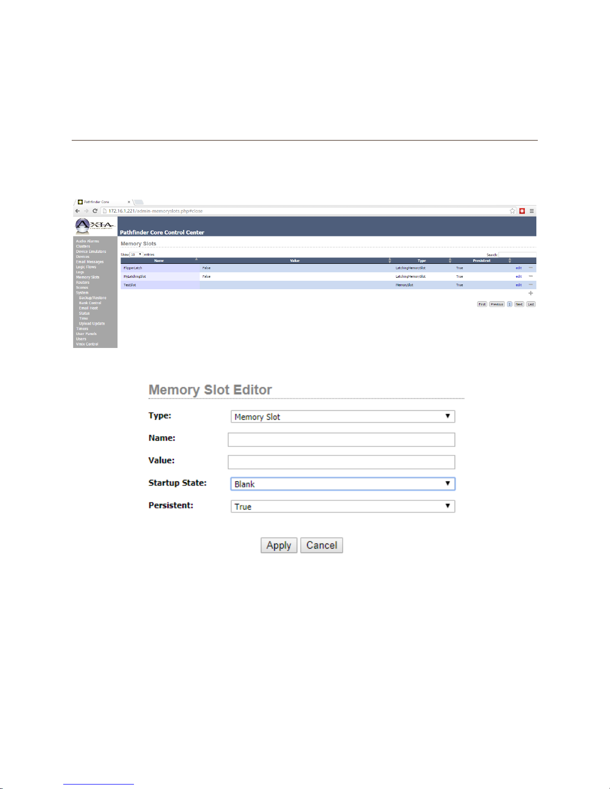
Chapter 7
Memory Slots
Pathnder Core Pro’s memory slots provide a named location for storing data that can be used in logic ows. You
can create and view memory slots via this link. You can also monitor the slot’s changes in real-time and alter the
value of a memory slot directly from this page.
Add a memory slot by clicking the plus icon on the right bottom corner of the memory slot list.
Pathnder Core PRO has ve different types of memory slots. Each one has its own options and properties:
• Memory Slot: This is the traditional memory slot into which any kind of data may be stored.
• Latching Memory: This memory slot can only have a value of True or False. Its write-only property is
called Trigger. Using a logic ow end point, you can set the trigger property to true and the slot value
will toggle from true to false, or false to true. See the latching example in the Logic Flows section of this
manual for more details.
• Numeric Memory Slot: This memory slot only accepts numbers. Its write-only properties are increment and
7: Memory Slots • 53
decrement. Use this in logic ows where you need to increment or decrement the value in the memory slot.
© 2017 Telos Alliance - Rev 1.2
Page 63
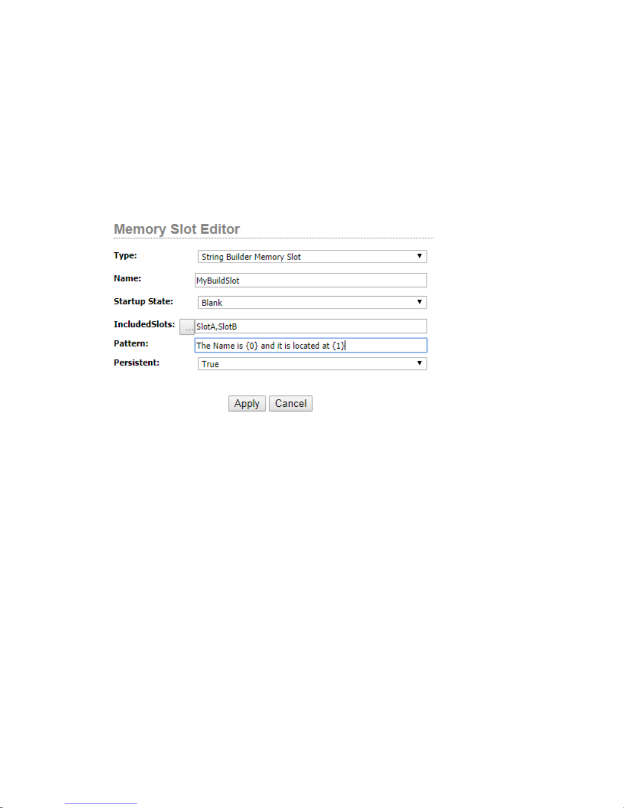
• Sap Property Memory Slot: This slot allows you to assign any property in the system to this memory slot.
When this property value changes, then the slot is updated with that value. The ellipsis button can be used
to select the property in the system to be used with this slot. It will present a property selection dialog similar to that of the dialog in Logic Flow endpoint editing.
• String Builder Memory Slot: This slot allows you to build a string based on values in other memory slots.
The “IncludedSlots” eld is used to enter a comma-delineated list of memory slot names to use in the builder. The pattern eld is a text pattern with bracketed numbers used where slot values from the comma-delineated list should be inserted. For example:
In this case {0} will be replaced with the value of slot A and {1} will be replaced with the value of slot B. If Slot
A’s value is Fred and Slot B’s value is Telos Alliance, the value of this new memory slot called MyBuiltSlot would
be: The Name is Fred and it is located at Telos Alliance. The value of this slot will update whenever Slot A or Slot
B updates. This slot can be used to build text to be used as labels on buttons or commands to generic translators.
When the included slot list contains slots that are Sap Property Memory Slots, this memory slot type can become
even more powerful.
The startup state drop down applies to each of the memory slot types above and requires some explanation. This
option allows you to determine the value of the slot when the system rst starts up and before any ows are
executed. It can be blank, a xed value as dened when you create the slot, or last known. It is important to
understand the last known option will attempt to store the state to the database each time the memory slot state
changes. This can be more cpu and time intensive because of the compact ash storage within the PathnderCore
PRO. As a result, use that option where it is needed and not in situations where the existing state of Axia devices
will reset the memory slot to the correct state via the ows as the ows start up anyway.
7: Memory Slots • 54
© 2017 Telos Alliance - Rev 1.2
Page 64
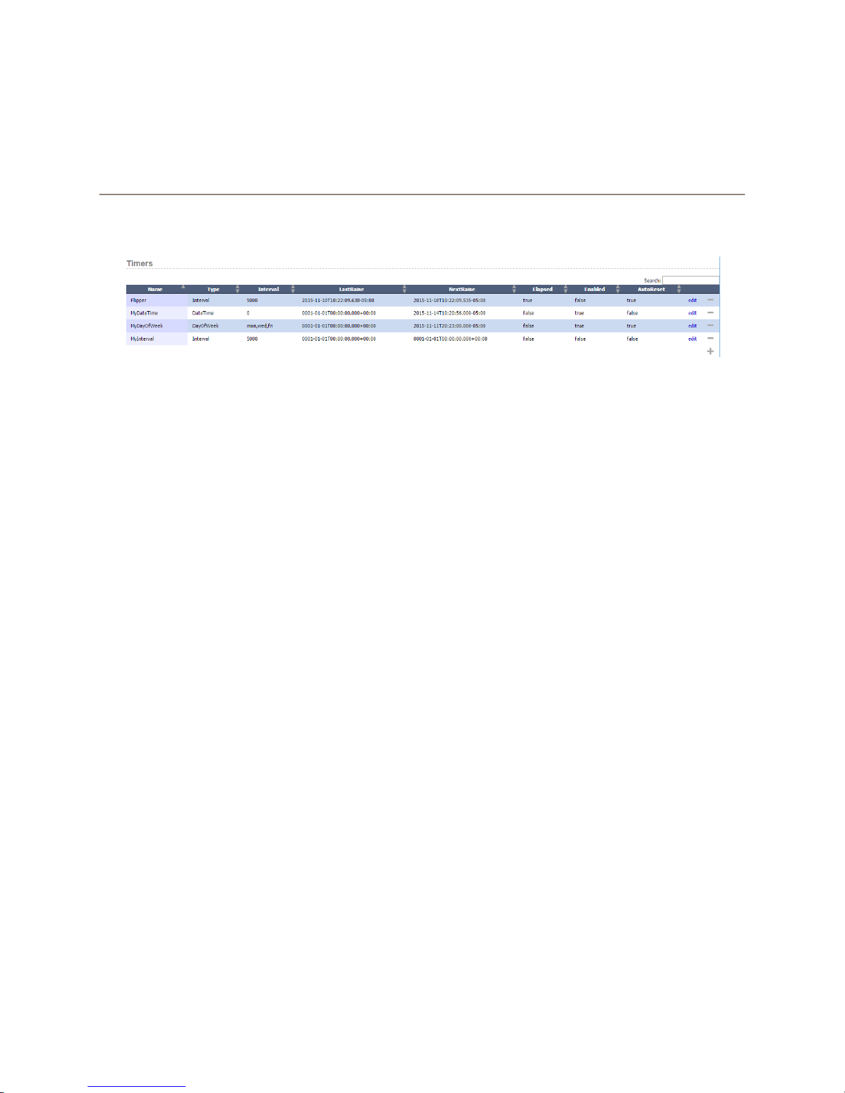
Chapter 8
Timers
There are no delays built into Pathnder Core PRO’s logic ows, but there are times when you need them. That’s
where the Timers page comes in to play.
This page shows up to date information as the timer states changes. The following columns are presented:
• Name: The name of the timer.
• Type: The type of timer.
• Interval: In the case of interval timers, this column will display the time in milliseconds. In the case of Day
of week timers, the column will display the days per week that are selected. This column is not used for
Date/Time timers.
• LastRaise: This column displays the date and time when the timer last elapsed. If the timer has never
elapsed, it will display a default minimum date time value.
• NextRaise: This column displays the date and time when the timer is next scheduled to elapse. If the timer
has never been enabled, this column may also show a default minimum date time value.
• Elapsed: The elapsed column will turn true if a timer has elapsed. It is important to note that if a timer is
set to Autoreset, this value will immediately turn false again.
• Enabled: This column displays whether the timer is currently enabled. A timer which is not enabled will
never elapse.
• Autoreset: Interval timers may be congured to AutoReset. When an auto resetting timer elapses, it will
automatically update its next raise time and starting counting down again.
• The edit link allows you to edit and change the parameters of a timer.
• The minus icon allows you to delete a timer from the system.
• The add icon is used to create new timers.
8: Timers • 55
© 2017 Telos Alliance - Rev 1.2
Page 65
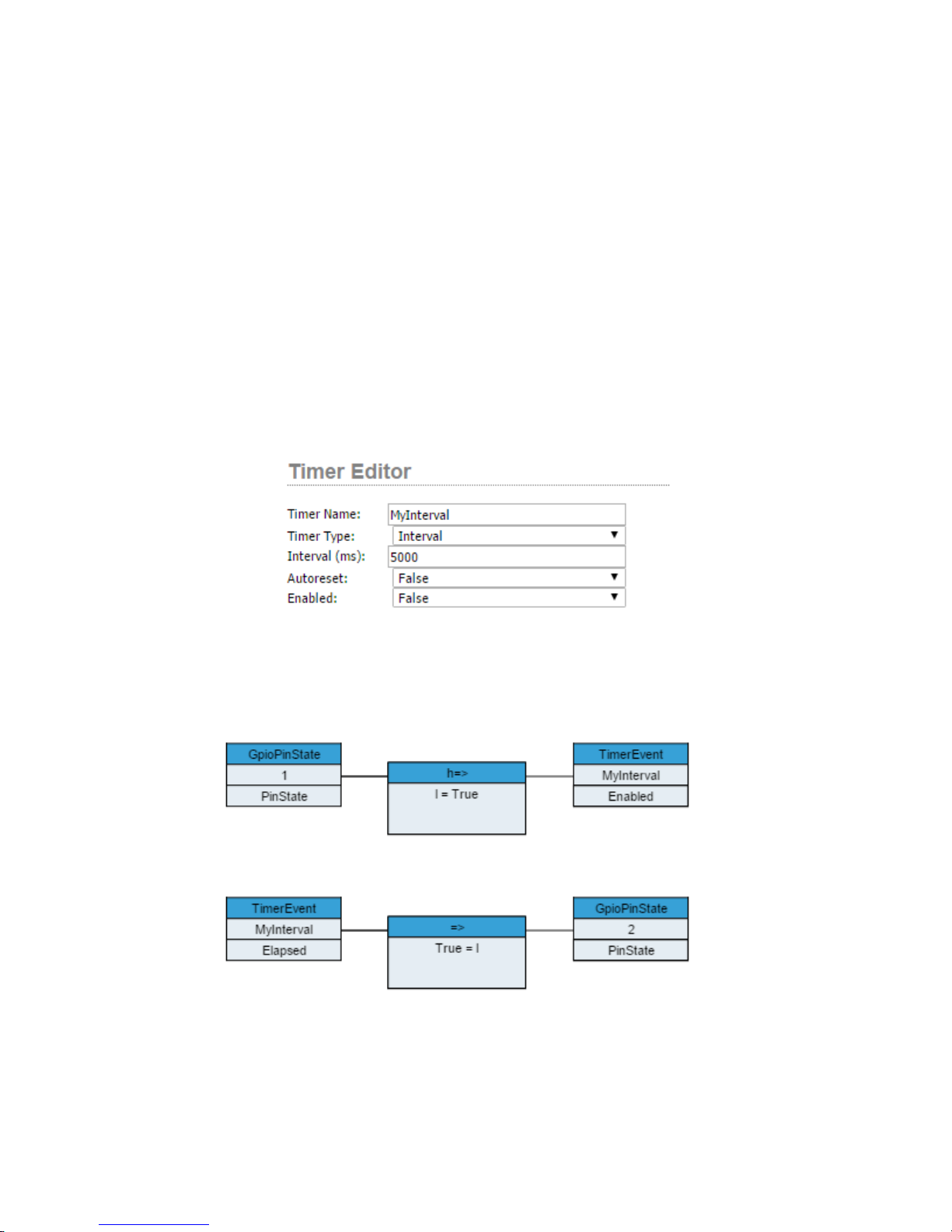
There are three types of timers that can be created in Pathnder Core PRO:
• Interval: An interval timer raises an elapsed property after a specied number of milliseconds. Interval timers can also be programmed to autoreset. An autoresetting interval timer will set elapsed to true after the
interval and then immediately set it back to false and restart the countdown.
• Date/Time: This allows you to specify a specic day and time. The timer’s elapsed property will be set to
true at that day and time.
• Day Of Week: This allows you to specify a time and the days of the week on which the timer should set its
elapsed property to true.
If you want to create a logic ow with a delayed action, rst create an interval timer. Leave the autoreset and
enabled properties as false. Give the timer a name and apply it.
8: Timers • 56
Now we can use this timer in the logic ows.
© 2017 Telos Alliance - Rev 1.2
Page 66
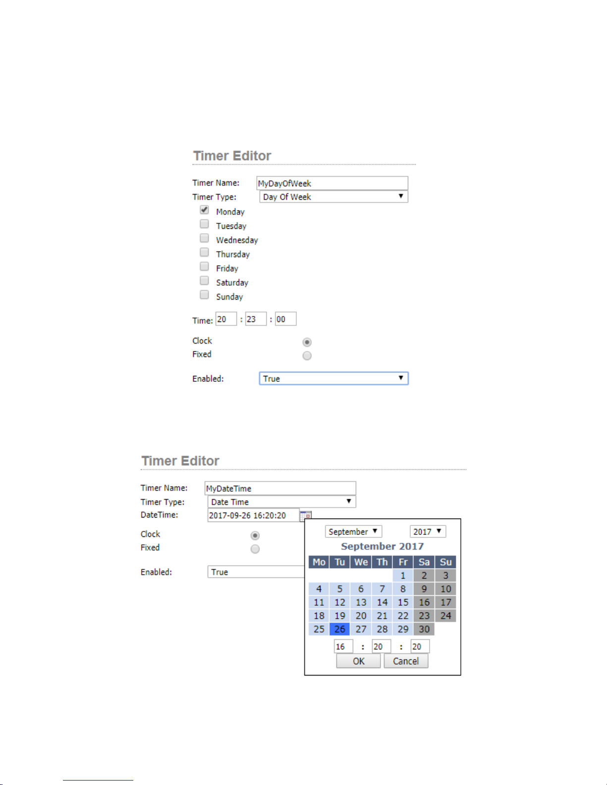
In this case, when GPI 1 goes low, it enables the interval timer. Then the elapsed property 5 seconds later causes
GPI 2 pin to be set low.
If we want something to happen at a specic time every Monday, we could create a Day of Week Timer.
8: Timers • 57
Or, if we wanted something to happen on a specic day and time, we could create a Date/Time timer.
Clicking the calendar icon will present a user-friendly calendar for conguring the date and time.
© 2017 Telos Alliance - Rev 1.2
Page 67
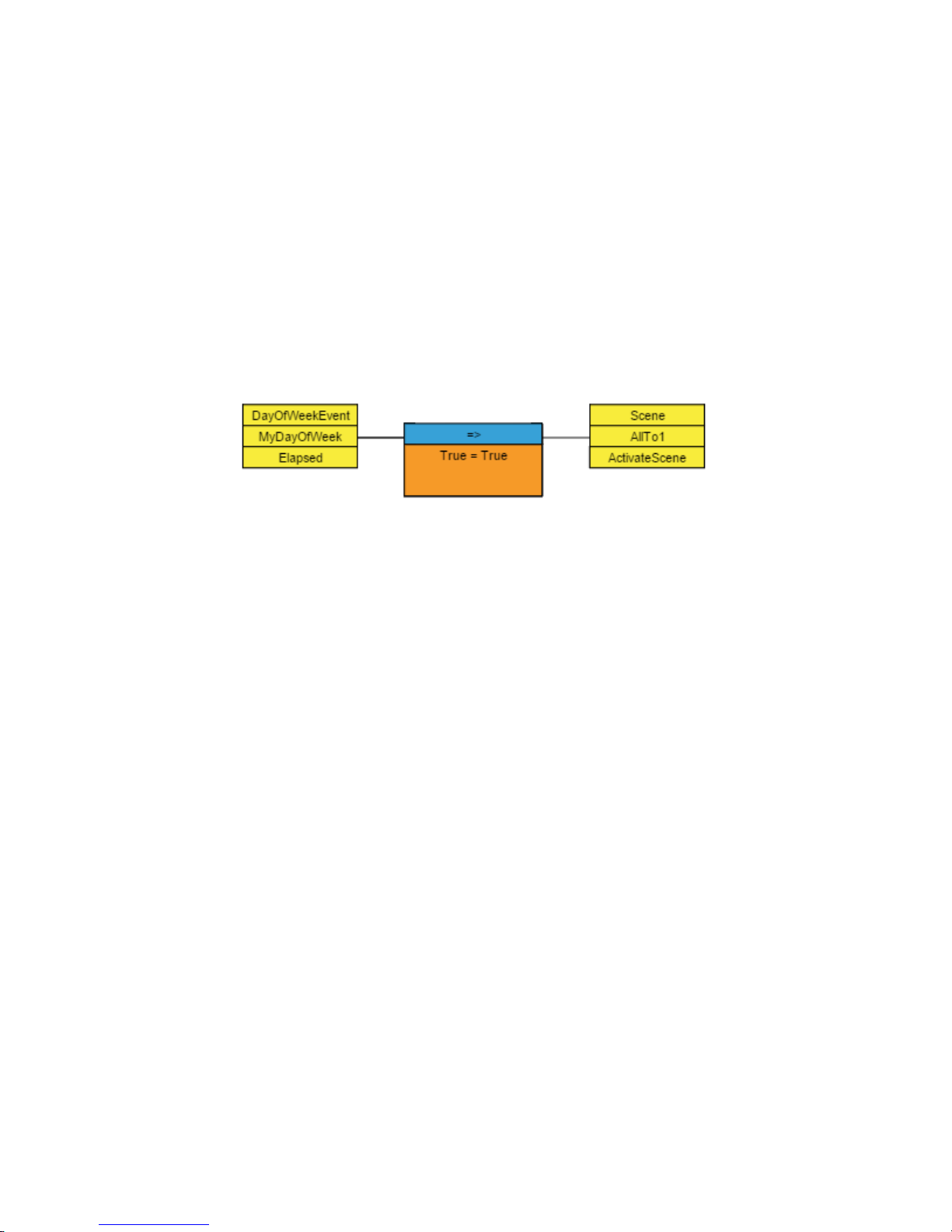
In both the Day Of Week and Date/Time timer, it is important to understand the difference between clock time and
xed time. Within PathnderCore PRO all times are stored with a UTC offset. Clock time means that the event will
happen at a specic time (say 7PM) according to the clock regardless of the UTC offset. So if you want an event
to happen at 7PM according to what the clock shows both before and after a daylight savings shift, then you should
pick the clock option. However, if you are picking up a satellite feed and the region from which the feed originates
does not shift their clock with daylight savings time, then you should select xed time because the event will happen
at a different time (according to your wall clock) before and after the daylight savings time shift. In this case it is
xed to the time and UTC offset.
It is also important to understand that creating a timer in Pathnder Core PRO will not actually cause any changes
to take place in the system. To do that, you would need to create a logic ow as shown above with a start point
that uses the timer’s elapsed property to then change some other property in the system. For example, if you
wanted to execute a scene change every Monday at a specic time, you would create a logic ow that uses the
DayOfWeek timer shown above.
In this way, we can use timers to cause delays, do repetitive operations (using the autoreset property of interval
timers), or execute actions at specic days/times and/or on a recurring daily schedule.
8: Timers • 58
© 2017 Telos Alliance - Rev 1.2
Page 68

Chapter 9
Scenes
In Pathnder Core PRO, scenes can only be created using the PathnderPC_Core client. See Chapter 18
PathnderPC_Core Client to review how to create scenes.
There are a few differences related to scenes under the hood in Pathnder Core PRO vs Pathnder Pro. One is that
there is a read only property which can be used in logic ows for each scene called IsActive. This means that in
addition to activating a scene with a logic ow or a client application or the web UI, you can also create logic based
on whether all of the points in the scene are currently in the requested state.
Another important difference is that under the hood a scene is nothing more than a set of API commands (See
appendix on SapV2 API). So a scene does not have to be just route changes or even route changes at all. You could
create a scene that sets a bunch of memory slots to specic values. Or you could create a scene that includes route
changes, fader changes, memory slot changes and button state changes. Unfortunately, there is no user interface
yet to make these kinds of scenes so in the current version unless you use the API, only route change scenes can be
created. In the future we will have a scene creation interface that allows adding different kinds of changes.
Once scenes are created using PathnderPC_Core Client, they will be listed and may be activated using the
Pathnder Core PRO web pages in addition to the PathnderPC_Core Client. Click on the Scenes link in the
navigation bar to view the available list of scenes:
9: Scenes • 59
The columns on this page are dynamic and will show the state of the scenes as they change. The columns included are:
• SceneName: The name of the scene. Scene names may be preceded by a number and an underscore in
some cases. These represent scenes created by PathnderPC_Core Client that are related to a specic
router number.
• IsActive: This shows dynamic information, and will display True or False depending on whether all of the
entries in the scene are currently in their requested state. The IsActive property is also available to logic
ows so that a ow can perform certain actions depending on whether a scene is active or not in addition to
actually triggering a scene.
• The Activate button on each line will cause all of the changes within a scene to be executed in Pathnder
Core PRO.
• The edit link is for future use.
• The minus icon allows you to delete scenes from the system.
• The plus icon is also for future use. Use PathnderPC_Core Client to create scenes.
© 2017 Telos Alliance - Rev 1.2
Page 69
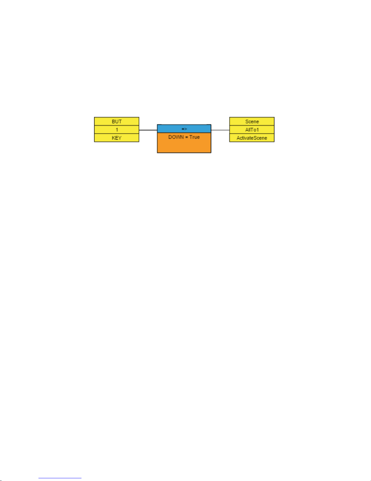
It is important to understand that when a scene is activated, the requests are sent by Pathnder Core PRO to the
required equipment, but in some cases the scene change might not be successful. For example, if an Xnode that is
involved in the scene is currently powered off, the scene change will not be completed. In this case the IsActive
state will not change to True.
Scene changes may be activated using Logic Flows using the ActivateScene Property. This property is a write only
property and will therefore only be available when editing end points. As an example, we could create a logic ow
that executed a scene change every time a specic LCD button was pressed.
9: Scenes • 60
© 2017 Telos Alliance - Rev 1.2
Page 70

Chapter 10
Audio Alarms
A very common use of logic ows in Pathnder Core PRO is to perform critical actions when an audio source or
destination falls silent. For example, you could have a logic ow send you an email if the feed to the transmitter
becomes silent. In order to accomplish this, you should use the Audio Alarms section of Pathnder Core PRO.
Almost any audio source or destination in an Axia network can be monitored for silence, clipping, and audio
presence. Click on the Audio Alarms link in the Navigation Bar to create, edit, and view audio alarms in the system.
As with other Pathnder Core PRO pages, this one will present dynamic data as the alarm states change. Nine
columns are displayed for each audio alarm:
• Name: The name of the alarm.
• Type: The type of the alarm. Types can either be Silence or Clipping. If you wish to know when audio
returns, use a silence alarm and then select the correct value for the Alarm state in logic ows. This will be
discussed in greater detail below.
10: Audio Alarms • 61
• Host: This displays the IP address of the device where the source or destination being monitored exists.
• SRC/DST: Displays whether the IO being monitored is a source or destination.
• IO: Displays the port number on the device of the input or output being monitored.
• Alarm Time: Displays the amount of time in milliseconds that the selected source or destination must be
silent (or clipping if the type is clipping) before the alarm is triggered.
• Release Time: Displays the amount of time in milliseconds that the selected source or destination must be
not silent (or not clipping if the type is clipping) before the alarm is released.
• Timer State: This column shows the current countdown to Alarm Time or Release Time. For example,
when a source being monitored goes silent, this column will show “CountingToAlarm”. Idle means that
the source or destination is currently in the state represented by the AlarmState column.
• Alarm State: This column represents the current state of the alarm. Possible values include Silent, AudioPresent, and Clipping. This value will only change after the source or destination maintains the requested
state for at least the amount of time in the Alarm Time or Release Time.
© 2017 Telos Alliance - Rev 1.2
Page 71
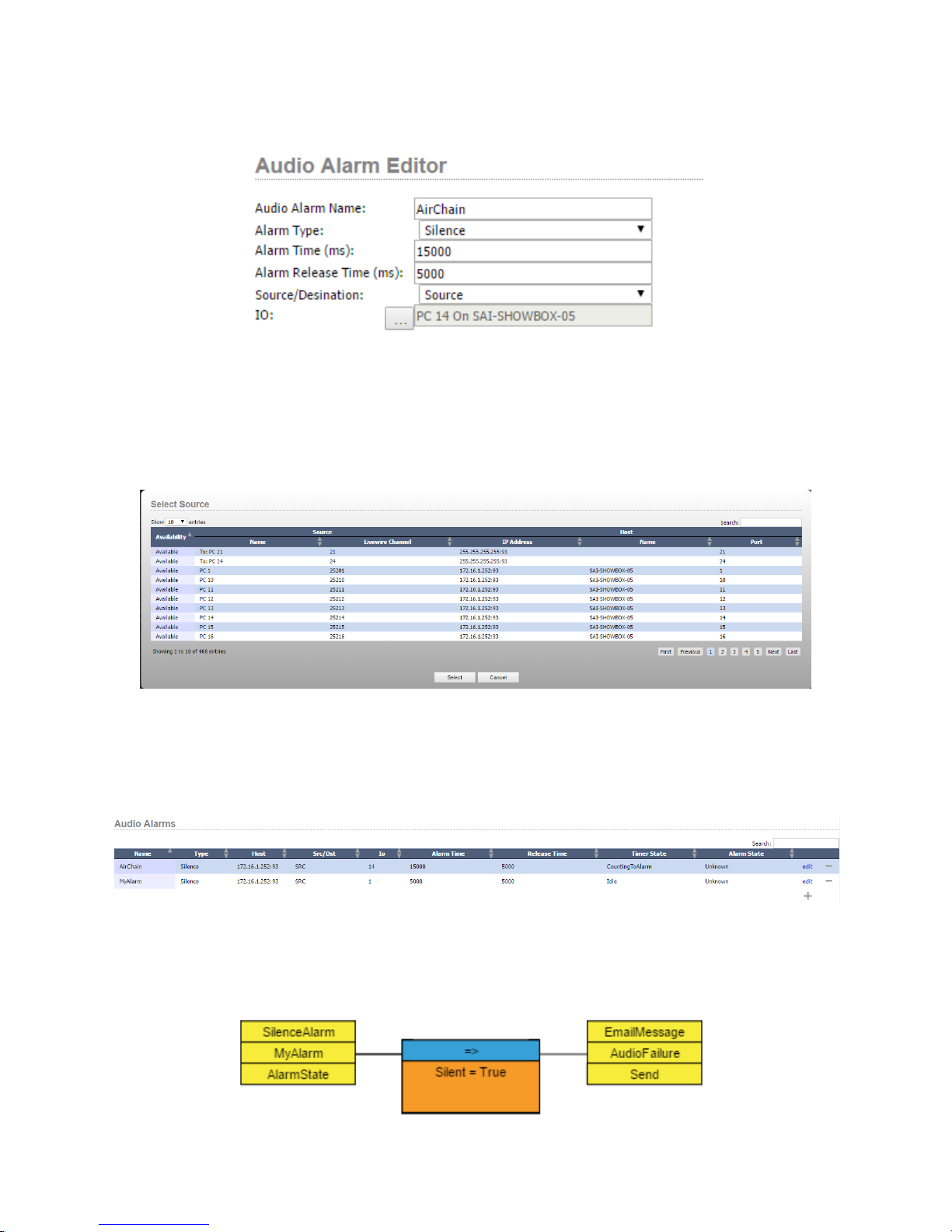
Let’s create an example. While on the Audio Alarms page, click the plus sign to add an audio alarm.
Provide a name for the alarm, in this case, AirChain. Select the type, in this case, silence. Alarm time is the number
of milliseconds the audio must be in the requested state before the alarm becomes active. Let’s make this value
15000 ms. Alarm release time is the amount of time it needs to be in the opposing state after an alarm has tripped
before the alarm clears. We’ll set that to 5000 ms. Select whether the alarm will be on a source or destination.
Finally, use the ellipsis button to choose from the list of available sources or destinations.
10: Audio Alarms • 62
Apply the changes.
It is important to remember that the list view of the alarms (like most lists in Pathnder Core PRO) show the alarms
in real time.
For example, the timer and alarm states will dynamically update on this screen as the alarm states change. This can
be an excellent troubleshooting tool. Once the alarm has been created, it is available for use in Logic Flows. In the
logic ow listed below, we have created a ow that sends an email whenever the MyAlarm audio alarm has its alarm
state switch to silent.
© 2017 Telos Alliance - Rev 1.2
Page 72
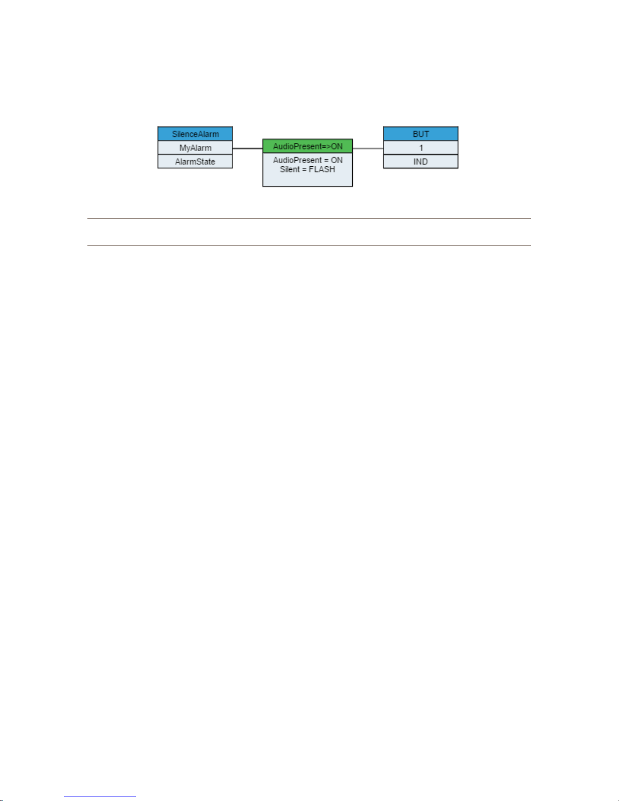
If we wanted to do a different action when the alarm releases (audio returns), just use the Audio Present value in the
translation list. For example, the following logic ow will light a button when audio is present, and cause it to ash
when there is silence.
Important Note: The thresholds used for silence detection and clipping are xed in the code and cannot
be changed. The silence threshold is set for -80db. The clipping threshold is set for -1db.
More examples of possible audio alarm ows are covered in the section on email messages, since that is a common
action to be taken when things get quiet.
10: Audio Alarms • 63
© 2017 Telos Alliance - Rev 1.2
Page 73

Chapter 11
User Panels
Pathnder Core PRO allows you to create your own custom user interface that can be displayed using the
PathnderPC Client and PathnderMini applications. This allows you to dene precisely how your users are
allowed to interact with your Axia system in a way that makes sense to your organization’s workow.
The PanelDesigner application is used to create user panels. See Chapter 19 PanelDesigner to review how to design
and create panels.
After the panels have been created and saved using PanelDesigner, the “User Panels” link in the navigation bar will
display the Panels that exist in the system.
This page will display the name, caption, and most recent version number in the form of a date/time stamp for each
panel. Panels may also be removed from the system using the minus icon next to each panel on this page.
Once the panel is created, properties for each of the panel’s controls are available to be used within logic ows.
There is a wide list of properties that are accessible to be used by logic ows in order to change colors, text, and
pictures on a panel as well as to react to button clicks and other control changes.
The list of available properties may be reviewed by browsing the start and endpoint property selection tree within
logic ows once the requisite panel has been created in the system. Additionally, most of these properties match
the property list described in Chapter 19 PanelDesigner. Review that list of properties if you have questions as to a
particular property’s purpose.
Once these panels exist in Pathnder Core PRO, they can be opened either in PathnderPC Client or by using the
conguration le with PathnderPC Mini. See details on how to use these panels in Chapter 18 PathnderPC_Core
Client, and also Chapter 20 PathnderPC_Core Mini.
11: User Panels • 64
© 2017 Telos Alliance - Rev 1.2
Page 74
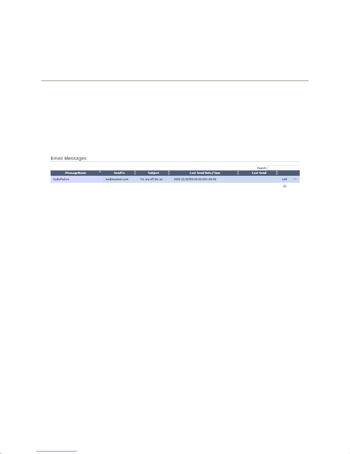
Chapter 12
E-mail Messages
Logic ows can be used to send e-mails when conditions exist in your system that require attention. For example, it
is fairly common to send e-mails to a variety of engineers when silence is detected at a transmitter site. In order to
send e-mails, you must rst congure the e-mail host settings under the System navigation section. If you have not
congured these settings please review Chapter 3 System, section 9 e-mail.
Once the e-mail host has been congured and test e-mails can be sent successfully, click on the Email Messages link
in the navigation bar.
This is where you can create e-mail messages that can be sent when specic actions take place in the system. The
information included on this page includes the following ve columns for each e-mail message:
• Message Name: The unique name of the e-mail message.
• SendTo: Displays the e-mail addresses to which the message will be sent.
• Subject: Displays the subject to be used by the e-mail message.
• Last Send Date/Time: Displays the last time the message was sent.
• Last Send: Displays information about whether the last send attempt was successful or failed.
• Edit: Displays a link to edit the conguration of an e-mail message.
As usual, the minus and plus icon can be used to delete e-mail messages from the system or to create a new e-mail
message.
12: Email Messages • 65
© 2017 Telos Alliance - Rev 1.2
Page 75
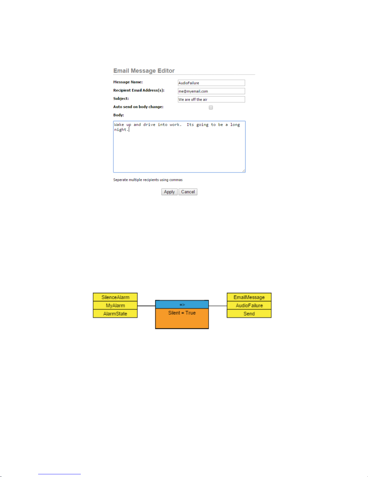
When you add a new e-mail message, the following dialog will be presented:
The Message Name property identies the e-mail when it is accessed via logic ows or API. The Recipient Email
Address eld is where you can place a comma delineated list of e-mail addresses to which the message will be sent.
The auto send on body change check box allows you to dene new body content in your e-mail via a logic ow and
have it send automatically without also having to set the Send Property. The Body is where you place the text of the
e-mail message.
Once created this e-mail message becomes available to be used by logic ows. In the following example, we will
send the Audio Failure email message whenever MyAlarm’s AlarmState becomes Silent. We accomplish this by
setting the write only property called Send to the value True.
12: Email Messages • 66
© 2017 Telos Alliance - Rev 1.2
Page 76
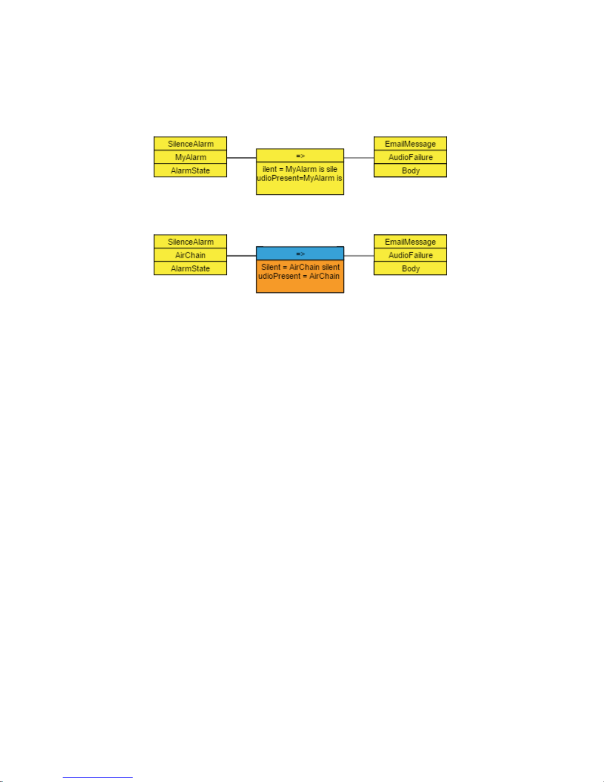
You can also change the body of the e-mail message as a logic ow end point. This becomes especially useful if you
have several conditions that could cause an e-mail alert. For example, we could create a generic e-mail message
making sure that the AutoSend on Body change checkbox is engaged. Then we could create multiple logic ows,
each of which alters the body of the message depending on the particular start point. For example:
Here we are actually using two logic ows to send four different messages to the same e-mail recipients.
• First Flow
» If “MyAlarm” is Silent -> Set the body of the “AudioFailure” message to be “My Alarm is Silent.”
» If “MyAlarm” has audio -> Set the body of the “AudioFailure” message to be “My Alarm is OK.”
• Second Flow
» If “AirChain” is Silent -> Set the body of the “AudioFailure” message to be “AirChain Silent.”
» If “AirChain” has audio -> Set the body of the “AudioFailure” message to be “AirChain OK.”
Since we engaged the option to send the e-mail each time the body property of the e-mail changes, this is all that we
need to do to handle four alarm conditions using one dened e-mail message.
12: Email Messages • 67
© 2017 Telos Alliance - Rev 1.2
Page 77
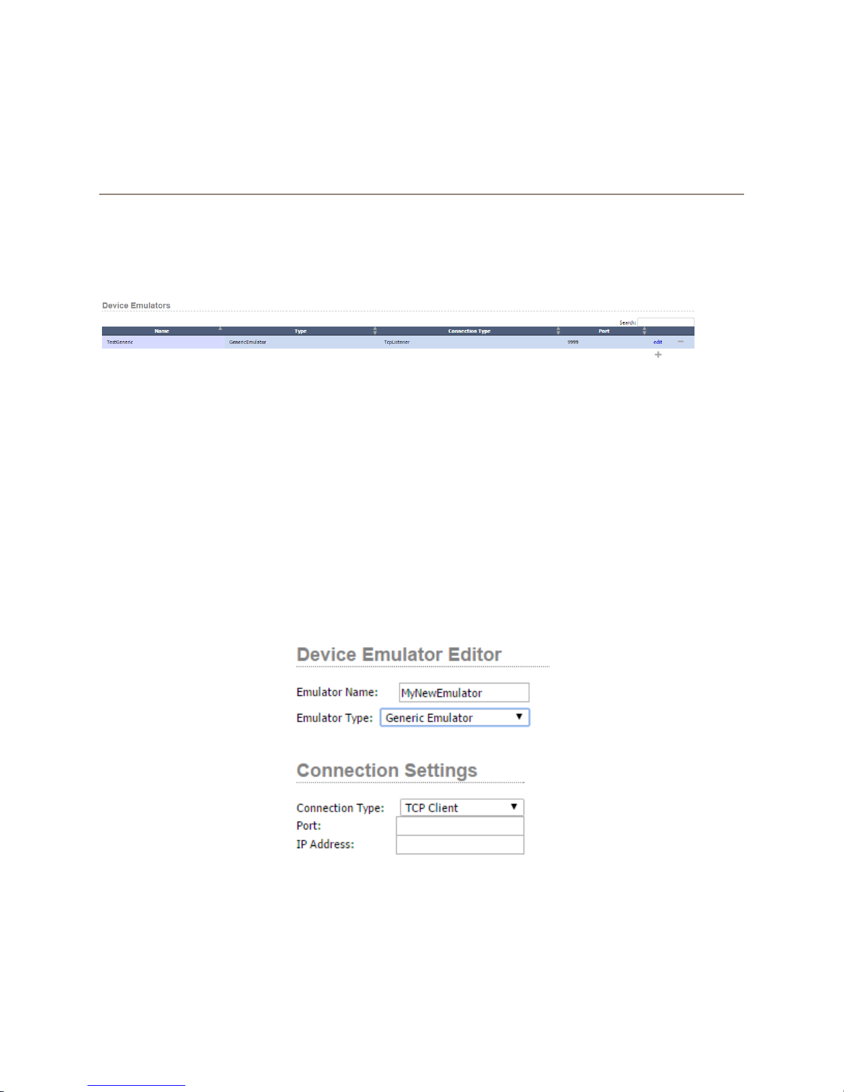
Chapter 13
Device Emulators
Pathnder Core PRO can emulate other routing systems. This can be particularly useful if you need to interface
with an automation system that has not implemented any of the protocols that drive Axia routing systems. Clicking
on the Device Emulators link in the navigation bar will display the list of device emulators currently dened in the
system.
The following four columns are present on this page:
• Name: The name of the emulator.
• Type: The type of the emulator (Generic, Probel General Router, Probel General Switcher).
• Connection Type: The connection type to be used with the emulator which can either be TCP Client or
TCP Listener.
• Port: The TCP port to be used for the connection.
Click the plus icon to add a new emulator.
Pathnder Core PRO currently supports three types of device emulation. Each emulator type may present slightly
different conguration options depending on the emulator type, and those conguration options are described below.
However, in each case you need to provide a name for the emulator, select the emulator type, and then dene the
connection parameters.
13: Device Emulators • 68
© 2017 Telos Alliance - Rev 1.2
Page 78
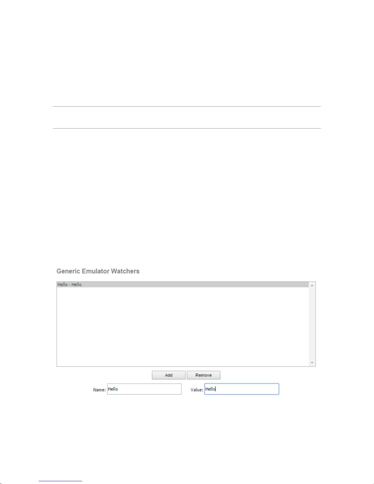
The connection type can either be TCP Client or TCP Listener. The primary difference between the two is whether
the system that will be using this emulator will establish the connection to Pathnder Core PRO or whether
Pathnder Core PRO should initiate the connection to the other device. If the other device will connect to
Pathnder Core PRO, then Pathnder Core PRO needs to listen for that device. In that case you should select the
TCP Listener option and dene the port on which Pathnder Core PRO will listen. If Pathnder Core PRO needs to
initiate and maintain the connection, then select TCP Client and dene the IP address and port of the device to which
Pathnder Core PRO should connect.
Important Note: Pathnder Core Pro does not have serial ports. If you need serial port control,
investigate serial-to-TCP converter solutions, or use Pathnder’s Port Router application to bridge the
serial data to TCP data.
After selecting the Emulator Type, the lower part of this dialog will present options that are specic to which
emulator type has been selected.
Generic
The Generic device emulator is just a TCP connection. It can be used to send and receive custom messages from an
automation system or some other third party system. Generic device emulators have a write-only property that can
be used by Logic Flows called ToSend. This property allows you to create a ow to send any kind of data out of the
generic emulator you wish.
This emulator can also be used to trigger actions depending on what data comes into the emulator. In order to dene
this, we can create watchers. Each watcher is looking for information coming to the emulator port, and if it sees that
data, it has a property called Triggered which will briey get set to True each time the data being watched for arrives.
To dene these watchers, use the section of the emulator editing dialog that appears when you select the Generic
Emulator Type.
To create a new watcher, click the Add button and select the newly created watcher from the list above. Then, dene
the name of the watcher and the value being watched for using the name and value elds. You can edit any watcher
by clicking it in the list and updating the values in these two elds. The Name of the watcher is used to identify the
13: Device Emulators • 69
watcher in the system. It will appear as an object underneath the emulator in the Logic Flows property selection tree.
© 2017 Telos Alliance - Rev 1.2
Page 79
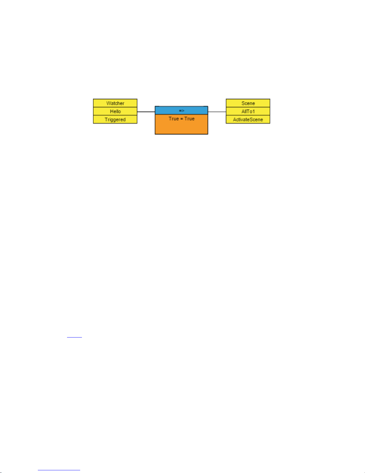
In the example above, we have created a single watcher on this device emulator called Hello, and it is watching for
the value Hello. If we see the word Hello come into this emulator, then the watcher’s Triggered property will be set
to True and then back to False so that it can wait for the next time it comes in.
Then we can create a logic ow where the start point is the triggered property of the watch point and do anything we
like in the system when we see the word Hello come in through the Device Emulator port.
In this ow we have dened that every time we see the word Hello on the watcher in question, we will activate the
scene AllTo1.
Escape Characters
Both the ToSend properties and the watcher values support a number of special character strings to represent special
characters.
• \cr: Carriage Return
13: Device Emulators • 70
• \lf: Line Feed
• \t: Tab
• \\: used to un-escape an escape
Therefore, a watcher that is watching for:
• MyName\cr\lf
Is looking for the word MyName followed by a carriage return and line feed. However, in the following example,
the double slashes are converted to a single literal slash for the case where you actually want to send the value \cr\lf.
MyName \\cr\\lf
Probel General Router and General Switcher
There are two Probel routing protocols supported by Pathnder Core PRO. They are Probel General Router and
Probel General Switcher. The syntax of these protocols differs and so it is important to consult the automation
system’s manual regarding which protocol to use. In both cases the protocol provides routing control. As a result,
after selecting this protocol type, the web page will present a drop down list with the available routers so that you
can choose which router the emulator will control. It is highly advised that you create a virtual router with only the
sources and destinations from the overall system that you want the emulator to control, and then select that virtual
router from this drop down.
© 2017 Telos Alliance - Rev 1.2
Page 80
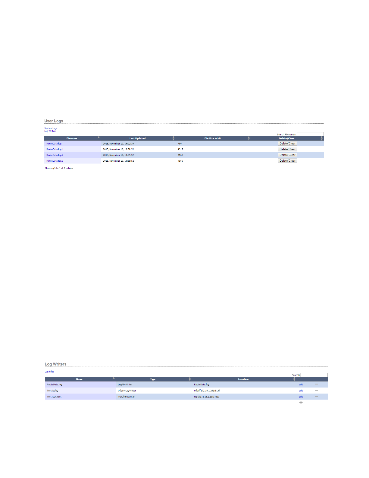
Chapter 14
Logs
Pathnder Core PRO provides a variety of different logging mechanisms as well as maintaining its own internal
system logs. Click on the Logs link in the Navigation bar to view the current logs in the system as well as to dene
logging options.
There are two kinds of log les created by the system. System logs and user logs. System logs are created by the
system’s internal services and primarily dene information for use by the developers. You can view these logs by
clicking on the System Logs link.
User logs can be created using the Log Writers link which will be discussed shortly. User logs are where you can
dene changes on your Axia network that you want to be entered into log les for later review.
Clicking on any of the logs will open the log for viewing in the browser. The rows for each log also display the le
size and last updated date and time, and nally, a button to delete or clear the log.
You may notice that some logs (such as the one in the screen shot above) have multiple copies with a period and
a number at the end. Due to space restrictions, Pathnder Core PRO maintains an intelligent log rotation service
which will rotate the log les if they are becoming too large, getting rid of the oldest information. In general,
log les get rotated 4x and the rotation happens when the le size reaches approximately 4MB. There are some
other rules which this service uses that might generate more aggressive log manipulation and/or deletion if space
is becoming limited. For this reason, it is recommended that you use an outside syslog based logging service to
capture logs that you wish to store for longer periods of time. This will be outlined in more detail in the LogWriters
section next.
In order to dene logging parameters click on the logs link in the navigation bar and then click on the Log Writers
link on the page that is displayed. This will present a page listing the log writers that have been created in the
system.
Each log writer in the system will be displayed on this page by Name along with its type and location. To create a
new log writer click on the plus icon.
14: Logs • 71
© 2017 Telos Alliance - Rev 1.2
Page 81
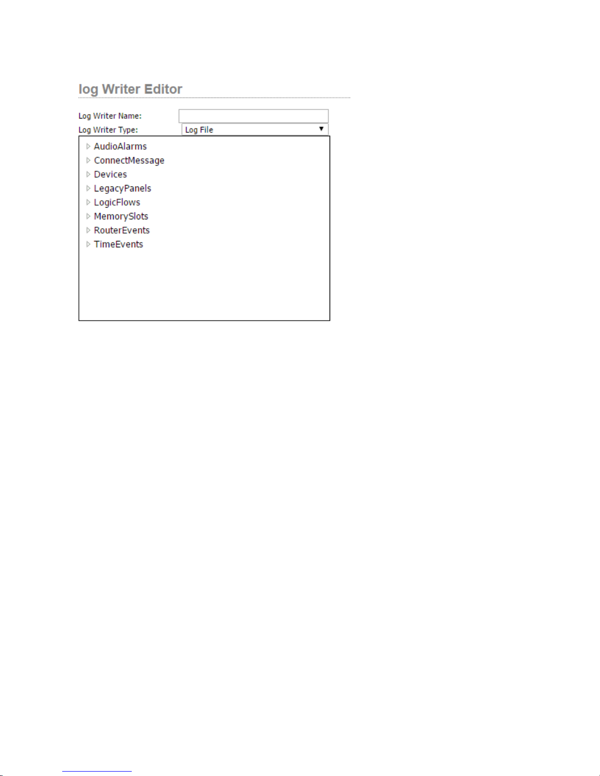
First provide a name for the log writer. Next select the type. There are four types of log writer that can be created:
• Log File: This type of log will be stored locally on the Pathnder Core PRO system. This means that the
log is subject to regular rotation, deletion, and cleanup depending on space requirements. Therefore it
should not be relied upon for long term storage. It is very useful for recent events though.
• TCP Listener: This type of log writer will listen on a TCP port and send the log entries as plain text mes-
sages to any application that connects. For example, you could use a putty (telnet) session to connect to the
system and monitor log changes dynamically.
• TCP Client: This type of log writer will attempt to connect to an IP address and port, and if it can make the
connection, will send the log messages as plain text messages to the listening application.
• Syslog: This is the recommended method for long term log storage. Syslog is a highly utilized standard
protocol for log collection, viewing, storage used by many systems and IT scenarios. A number of syslog
collection applications exist, both freeware and commercial. A quick internet search should provide you
with a variety of options.
Once you choose the log writer type, you may be presented with a number of additional pieces of information to ll
in regarding the connection specics. These can include IP addresses and TCP port numbers. The required options
will appear according to which log writer type you select.
14: Logs • 72
© 2017 Telos Alliance - Rev 1.2
Page 82

Finally, you need to use the selection window at the bottom of this dialog to select what log options you wish to log.
Expanding the tree in this window will present checkboxes for the items you wish to log. The available items are:
• AudioAlarms
» AlarmState: Generates a log message whenever an audio alarm state changes.
» LvlState: Generates a log message whenever the audio threshold for silence is passed for longer
than 250 ms. This occurs before the countdown to an alarm state begins. It can be used to log the
actual transitions being reported by the equipment but may also generate a large amount of log content depending on the type of audio content being monitored.
• ConnectMessage
» Connected: Logs connections and disconnections from equipment. Use this log message to nd
equipment with which Pathnder Core PRO is struggling to maintain a connection.
• Devices
» VMIXGain: Logs changes to VMIXer gain settings.
» VMIXState: Logs changes to VMIXer On/Off settings.
• LegacyPanels
» PanelPropertyChanged: Logs changes to properties of any of the controls in user panels.
• LogicFlows
» CombinerOutputChanged: Logs changes whenever a logic ow translator changes its output.
» TranslatorOutputChanged: Logs changes whenever a logic ow translator changes its output.
• MemorySlots
» MemorySlotChanged: Logs whenever a memory slot changes its value.
• RouterEvents
» GPIO State: Logs changes to GPIOs within the system.
» RouteState: Logs any route changes that take place within the system.
14: Logs • 73
© 2017 Telos Alliance - Rev 1.2
Page 83

• TimeEvents
» Elapsed: Logs whenever timers elapse.
» Enabled: Logs changes to a timer’s enabled state.
Please note that this list is subject to change in future software revisions.
14: Logs • 74
© 2017 Telos Alliance - Rev 1.2
Page 84
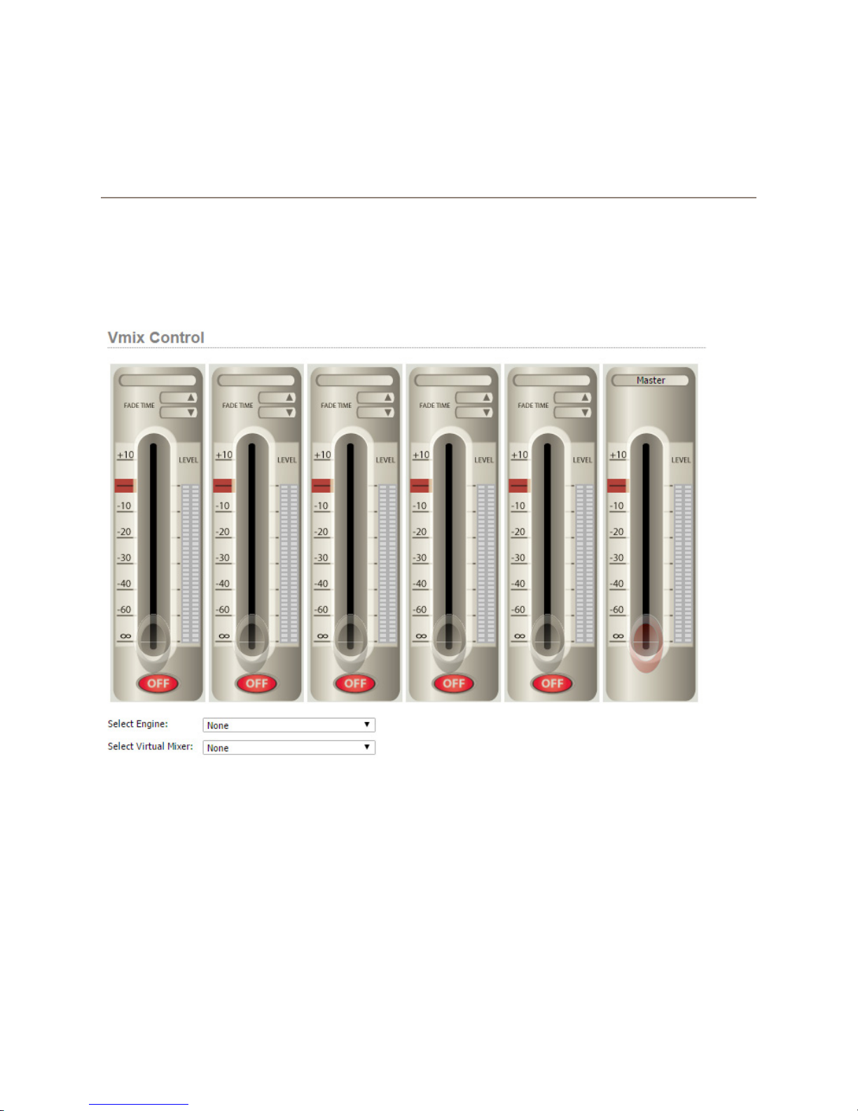
Chapter 15
Vmix Control
One of the powerful features of Axia Audio mixing engines are their virtual mixers. The Element and Fusion mix
engines include sixteen virtual mixers which can be used to create mixes of various audio streams. These virtual
mixers can be controlled using logic ows to dynamically create mixes of audio content based on changes in the
system. Additionally, there is a web page for managing these virtual mixer, in effect creating an on-screen mixer. To
access this user interface, click on the Vmix Control link on the navigation bar.
When you rst open this web page, the faders will be dimmed out and none of the buttons will function, as you rst
need to tell the page which engine and which Vmixer to control. Select the mix engine from the Select engine drop
down. And then select one of the 16 virtual mixers from the Select Virtual Mixer drop down.
15: Vmix Control • 75
© 2017 Telos Alliance - Rev 1.2
Page 85
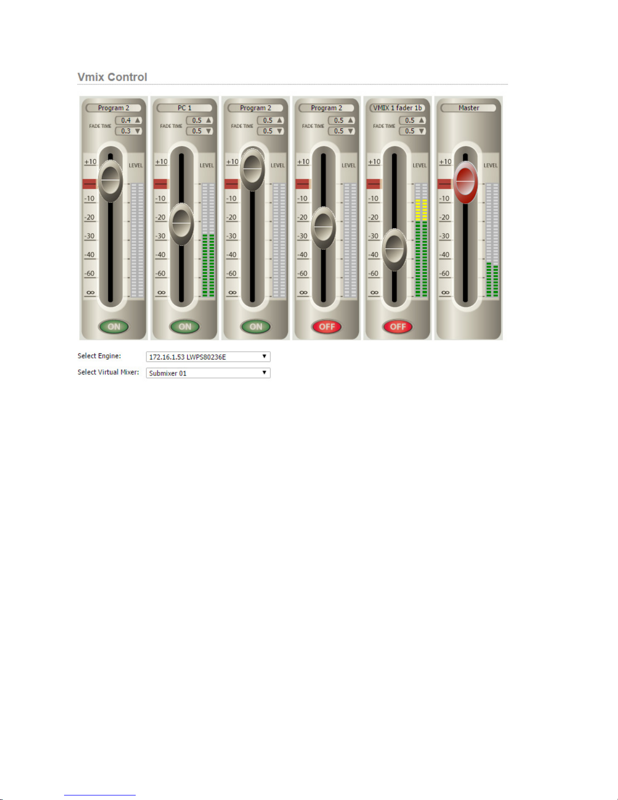
The interface will now update to display the state of the virtual mixer selected. You can use the drop-down lists to
switch between different Vmixers.
Each Vmixer has 5 input channels and a master fader. The master fader is labeled as master and has the red fader.
The meters for the input channels display the real-time metering of the source assigned to each of the faders. This
metering is pre-fader so it is showing you the level of incoming audio. The meter next to the master fader is
displaying the level at the output of the virtual mixer and is therefore post Master fader.
Dragging a fader on the screen up or down will adjust the VMixer channel’s gain.
Clicking the On/Off buttons will turn a fader on and off. It is important to note that turning a virtual mixer fader
on and off is subject to the fade up and fade down time parameters. These can be changed by clicking on the elds
next to the up arrow or down arrow in the Fade Time section. Times are entered in seconds. So if you have a fade
up time of 1.2 seconds, when you click the On button the audio will fade in to the level dened by the fader over
the course of 1.2 seconds. Then the fader control will dynamically allow you to control the level. The same is true
when turning the fader off. Clicking the off button will fade the audio out dependent on the fade down time.
15: Vmix Control • 76
© 2017 Telos Alliance - Rev 1.2
Page 86
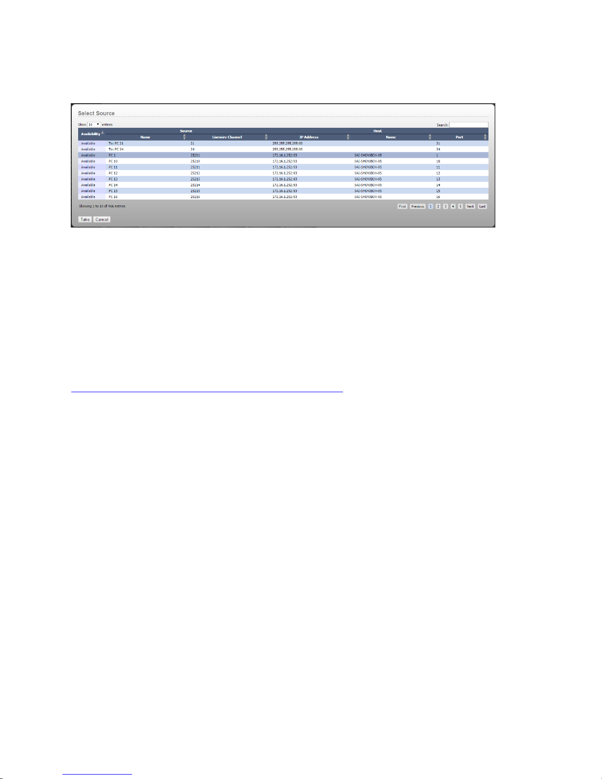
Finally, clicking on the source name at the top of each fader will allow you to select a different audio source for the
fader. A list of available sources will appear.
Highlight the new source and click take to select the new source for the fader. Or, click cancel to return to the mixer
web page.
Vmixer Shortcuts
It is also possible to generate direct links to a particular Vmixer. This can be useful if you wish to create a shortcut
on a user’s desktop that will present a specic Vmixer. In order to create such a shortcut in Windows, right click on
the desktop and select new shortcut. For the location type:
http://172.16.1.221/vmixcontrol.php?engine=172.16.1.63&vmixer=1
Replace the 172.16.1.221 with the IP address of your Pathnder Core PRO. Replace the 172.16.1.63 address with
the address of the mix engine you wish to control. And replace the 1 at the end of the link with the virtual mixer
number within the engine you wish to control. Then click next and provide a name to create the shortcut. And
nally, click nish. Or, just enter the address into the address bar of the user’s browser and then add it to favorites.
When you create the link this way, the user will not see Pathnder Core PRO’s navigation bar or the drop downs to
select a different engine or Vmixer. The web page will only present the specied virtual mixer.
15: Vmix Control • 77
© 2017 Telos Alliance - Rev 1.2
Page 87
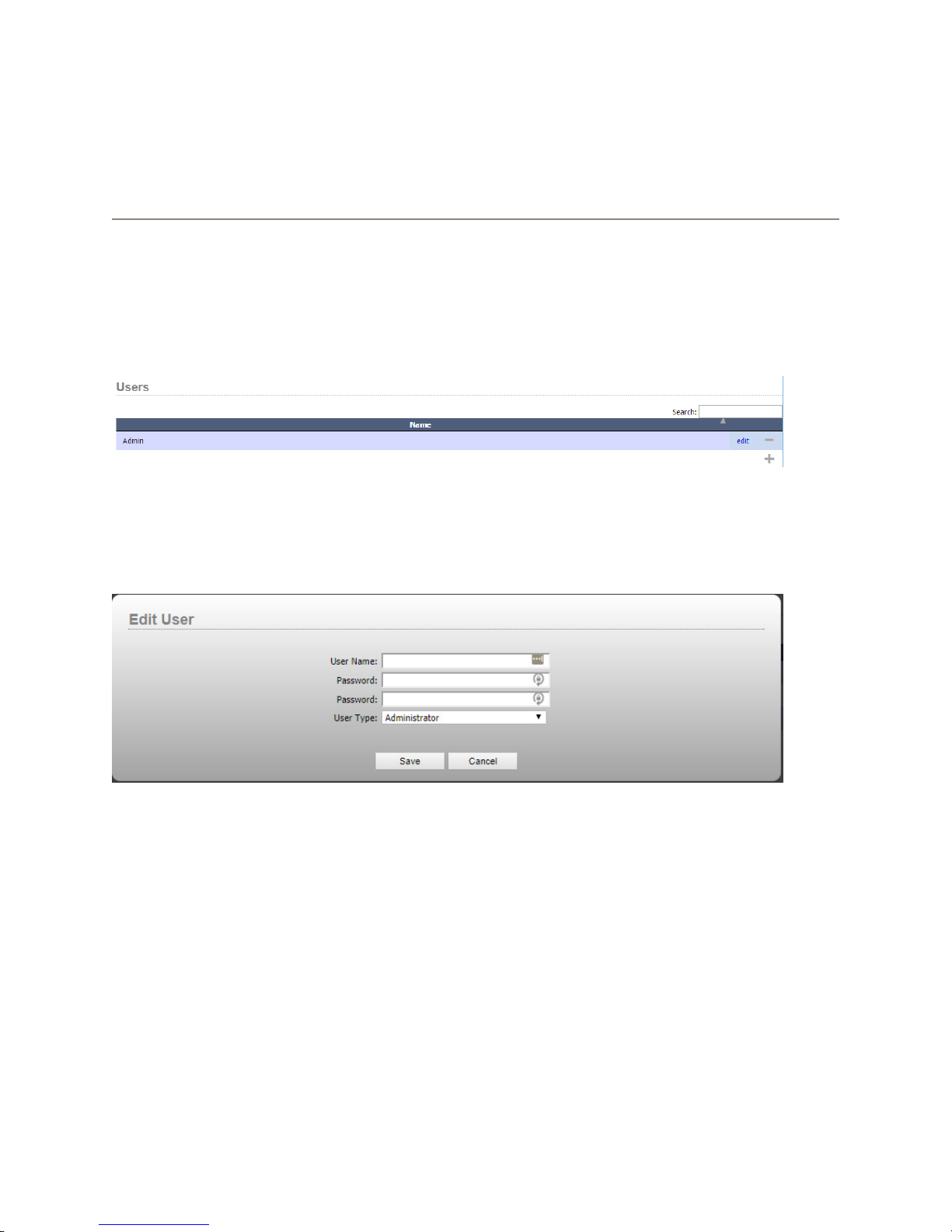
Chapter 16
Users
When you rst log in to Pathnder Core PRO, the username and password you use is:
Username: Admin
Password: Admin
However, this can be changed and controlled using the Users link on the navigation bar.
Click edit to change a user’s password or click the plus icon to add users to the system. Use the minus icon to delete
users from the system. The system will not allow you to delete all users. At least one user must always exist in the
system or there is no way to use it. Therefore, the user interface will show an error message if there is only one user
left and you try to delete it.
After creating a new user, that user’s credentials may be used to log into the Pathnder Core PRO’s web pages or
using PathnderClient, PathnderMini, or PanelDesigner.
Users may be Administrative users who have acces to everything or standard users. It is very important never to
delete all of the Administrative users or you may lose access to the system requiring support to get access to the
operating system to reset things. If you select a standard user, additional options will appear for dening what rights
the user has.
16: Users • 78
© 2017 Telos Alliance - Rev 1.2
Page 88
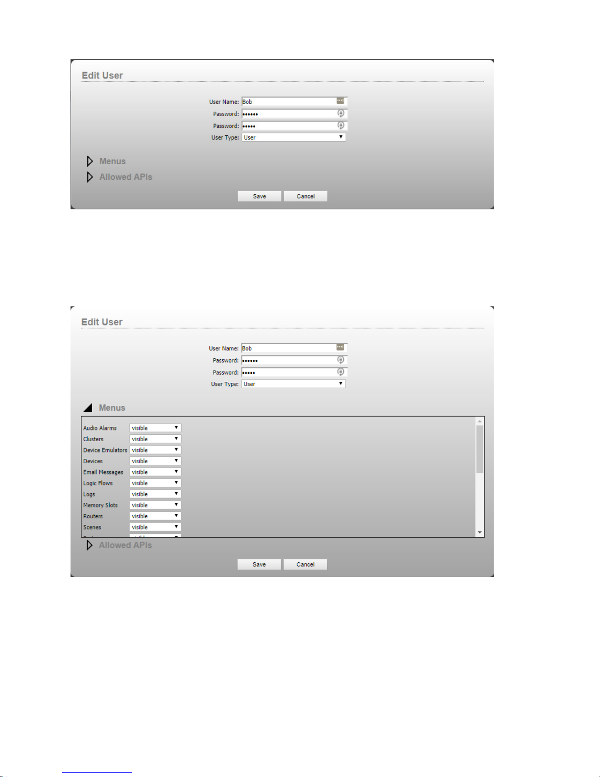
The arrows next to each section may be expanded to specify the user rights. By default a standard user will see
all navigation menu items but will have no rights in the api so most or all of the menu items will not populate
with any data.
The menus section allows you to dene which navigation bar menu items are available to the user.
The menus listed are the same as in the navigation bar on the web page. By setting items to hidden they will no
longer appear in the user’s navigation bar.
16: Users • 79
© 2017 Telos Alliance - Rev 1.2
Page 89
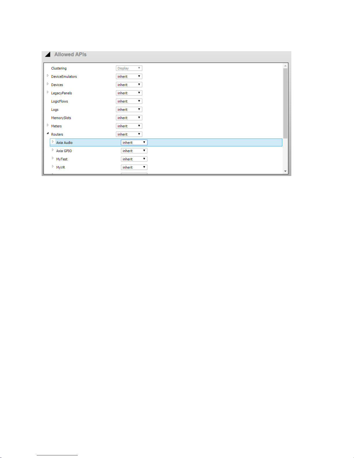
The allowed APIs section denes in much more detail what the user may access via the web pages, port 9600 login,
and the client applications:
Each item in the displayed list has several options:
• Inherit means that branch in the tree inherits the rights of the parent branch. In the case of root level objects such as Logic Flows the inherited state is No Access.
• No Access explicitly denies access to that branch.
• Display allows the user to display the resource but not change or use it. For example, if you wanted the
user to be able to view the route states of a router but not make any route changes, then selecting display
for the router access would be a good idea.
• Change/Use allows the user to do normal operations with the resource but not change the denition of the
resource. For example, in the case of routers, selecting change/use would allow the user to make route
changes on the router but would not allow them to add sources or destinations to the router.
• Full access allows the user to have complete control over the resource including the ability to add to or
delete the resource. This is the equivalent of Administrative rights to the resource.
It is important to note that by default branches below a specic branch inherit the parent’s properties. So, if you set
the Routers branch to display, all routers will be displayed. You can then set no access on routers you do not want
the user to see and/or Change/Use access to routers you want them to be able to use.
16: Users • 80
© 2017 Telos Alliance - Rev 1.2
Page 90
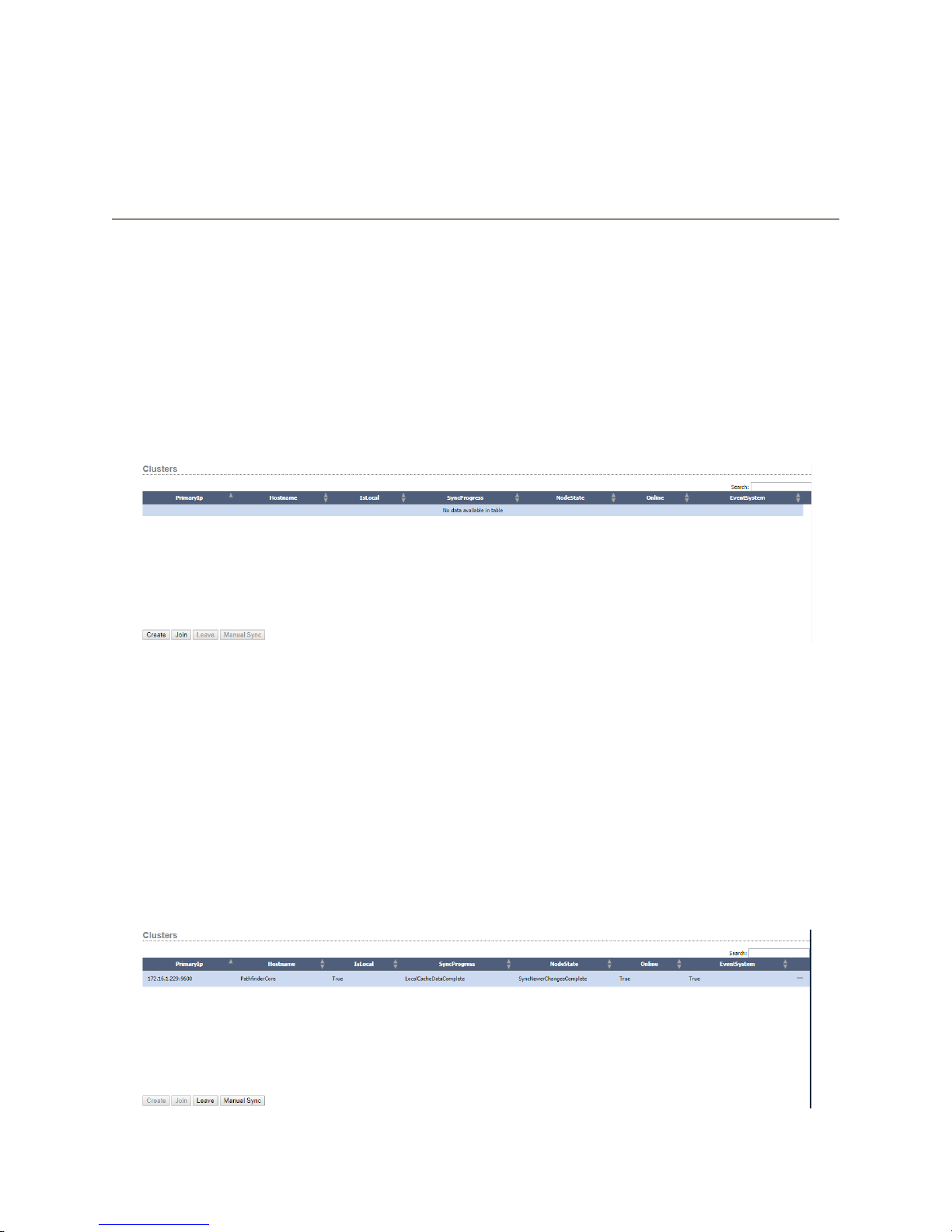
Chapter 17
Clusters
If you are concerned about hardware failures, then Pathnder Core PRO clustering is for you. Pathnder Core
PRO allows you to add multiple Pathnder Core PRO systems onto the network, and connect them together so that
they automatically and dynamically share conguration data and states. They also monitor each other, taking over
processing events if one of the systems fails.
The rst step is getting your system to work close to the way you want it to function with a single Pathnder Core
PRO. Allow the routers to be created and add other events and components you wish to have running on your
system. Next, take a backup of your conguration and download it to your local computer. See the section on
Backup/Restore for more information. This will guarantee you can get back to your current operational state if you
make a mistake when setting up your cluster. Next, click on the clusters link in the navigation bar.
17: Clusters • 81
Four buttons will be presented at the bottom of this page; Create, Join, Leave, and Manual Sync. The Leave and
Manual Sync buttons are unavailable because the system is not currently a part of a cluster.
Creating a Cluster
First, click Create to create the cluster. The system will ask you to create a cluster administration password. This
password is important because it will be used throughout the cluster so that the Pathnder Core PRO units can log in
to each other and synchronize data. When you provide this password, the system will create a special ClusterAdmin
user for this purpose. You will be able to see this user when you view the Users navigation link and a severe
warning will be issued if you try to change the password of that user since it must be identical across all systems.
Once the cluster has been created, the Clusters link should look something like this:
© 2017 Telos Alliance - Rev 1.2
Page 91
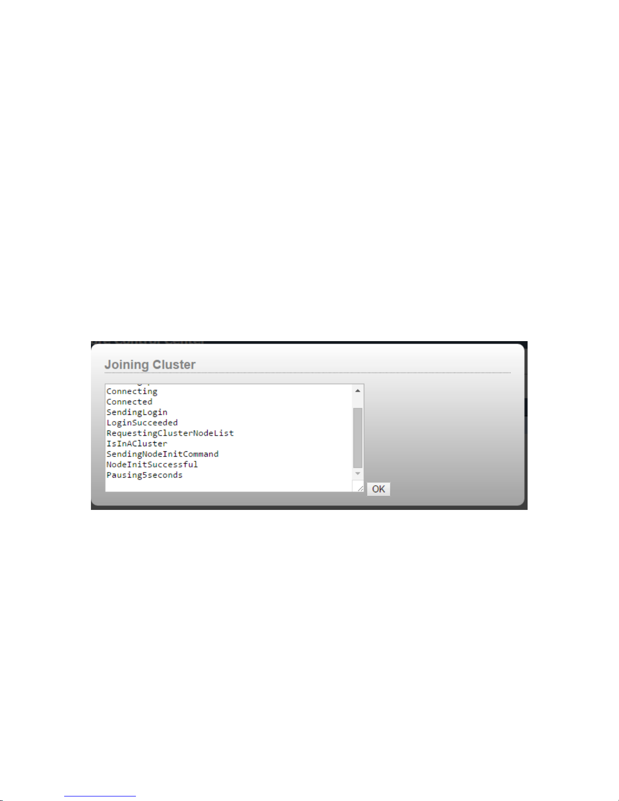
The system is now part of a one node cluster. This display will show the hostname and IP address for each node in
the cluster. When there are more than one systems in the cluster, the IsLocal eld will show which of the systems
you are currently logged into. It will also display the state of each Pathnder Core PRO system in the cluster. The
minus button should only be used in the rare situation where you need to forcefully remove a non-functioning node
from the cluster. The preferred method is to go to the node to be removed and click the Leave button.
Joining a Cluster
Now it’s time to add the second system into the cluster. It is important to note that the second system’s
conguration will be overwritten during this process. If the system is new, make sure you rst assign an IP address
using the front panel. The IP must have network access to the rst unit in the cluster, so pay attention to the network
conguration. You do not need to enable Livewire discovery on this second system.
On the second system, browse to the clusters link on the navigation bar, and then click the Join button. The system
will ask for the IP address of any Pathnder Core PRO system that is already a part of the cluster. It will also ask for
the cluster administration password you provided when you created the cluster.
The system will now pop up a progress message box as the system joins the cluster.
17: Clusters • 82
© 2017 Telos Alliance - Rev 1.2
Page 92

The join process involves telling the rst system that the new node is joining the cluster. It will then ask the rst
system to generate a special backup. The second system will download that backup and restore and then reboot. At
that point, the cluster should be created and you should be able to see both systems on the cluster page.
A successfully synchronized cluster should show all node states on the web page of all systems as
SyncNewerChangesComplete. If that is not the case in your cluster and it does not resolve to that state within a few
minutes after a restart, then contact Axia support to help determine why the cluster is not synchronizing properly.
Follow this procedure with subsequent Pathnder Core PRO systems you wish to have join the cluster.
Once the cluster is created, changes to the conguration and state information are automatically synchronized across
the Pathnder Core PRO systems in the cluster. Additionally, in the case of a failure of one of the Pathnder Core
PRO systems, one of the other systems will begin processing the events. See the section on Events and Timers for
more information.
Manual Sync
Sometimes it may be desirable to force the cluster into synchronicity if there is some doubt that it is properly
synchronized. In order to do this, browse to the system that is incorrect (out of sync) select the cluster menu item
and select the manual sync button. This will ask for conrmation and then will request a backup from the other
(known good) system, download and restore that backup and then reboot. This is usually a procedure that would be
performed in the context of an Axia support session.
Leaving a Cluster
If you wish to leave a cluster, make sure that the system is connected to other nodes in the cluster. Then click on
the Clusters link and click the Leave button. The system will revert back to a stand-alone system. It is important
to note that after leaving a cluster, the conguration will still be the same as it was prior to leaving the system. It
is recommended to quickly remove the system from the network and/or factory default the system. Otherwise, the
system may start trying to process events that the rest of the cluster is also trying to process.
17: Clusters • 83
© 2017 Telos Alliance - Rev 1.2
Page 93

Events and Timers
There are a number of elements of a Pathnder Core PRO system that should only execute on a single system at
a time so that a cluster is not requesting duplicate changes from a device. Examples of this are Logic Flows and
Timers. Those will always execute on the system that is currently active and has the lowest IP address. Heartbeats
are constantly sent and monitored between the systems so that if a system stops responding the next lowest IP
address system will take over those responsibilities.
Clustering and SapV2
SapV2 is the protocol that is used both for cluster communications and for internal communications. This protocol
is available on port 9600 and is described in more detail in the appendix of this manual. If the cluster does not seem
to be working properly there is a great deal of information that can be collected about the clustering process using
this protocol to try and solve the problem.
17: Clusters • 84
© 2017 Telos Alliance - Rev 1.2
Page 94
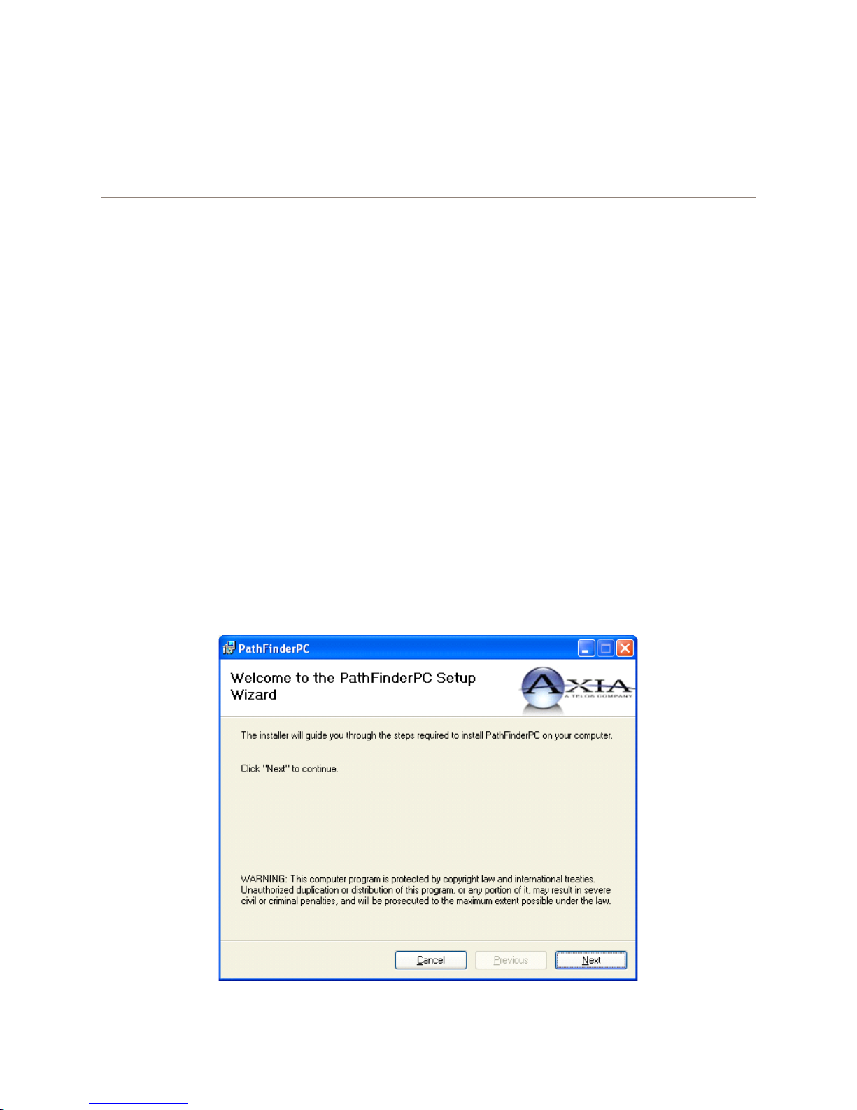
Chapter 18
PathfinderPC_Core Client
PathnderPC_Core Client is a desktop application that users can use to make routing changes with the Pathnder
Core PRO system. It communicates with Pathnder Core PRO over TCP/IP on the local LAN and/or over the
Internet. It can be used to make routes, create and edit virtual routers, and to create, edit, and activate scene changes.
It also has a search engine for nding route points and scenes. Finally, it can display and manipulate user panels that
have been created in the system.
PathfinderPC_Core Installation
The installer for PathnderPC_Core Client may be downloaded from the Pathnder Core PRO System web page.
The client software may be installed on any Windows machine on the network that is to be used for making routing
changes.
To Install PathnderPC_Core Client:
• Click on the System web page in PathnderCore PRO.
• Click on the PathnderPC Core Client link and download the PathnderPC_Core Client installer.
• Double Click on the PathnderPC_Core client installer to install it.
18: PathnderPC Client • 85
© 2017 Telos Alliance - Rev 1.2
Page 95
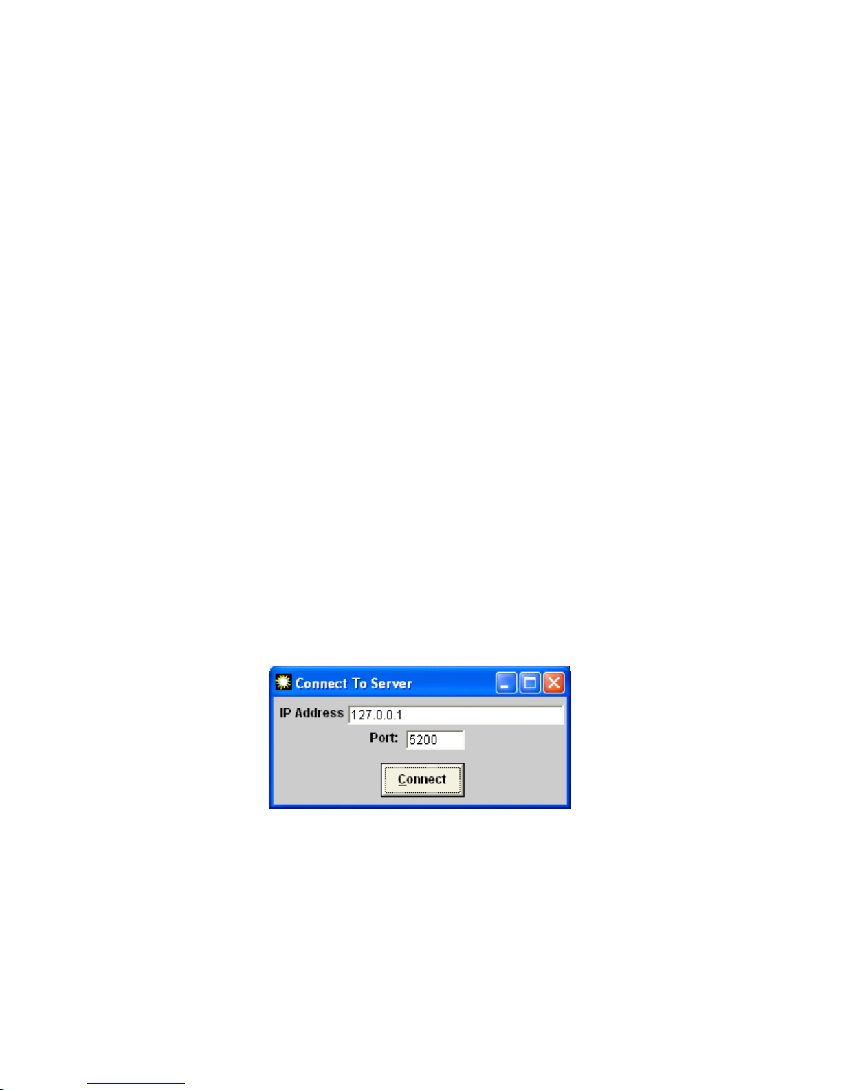
• Click Next to begin the installation.
• Click I Agree to the license.
• Click Next again.
• Select the location for installing the application or leave it at the default.
• Click Next a nal time to nish the installation procedure.
• If the application is being installed on Windows 7 or later, it is recommended that the following option also
be turned on to ensure PathnderPC_Core Client has the ability to properly manage its own les:
» Find the PathnderPC_Core.exe application located in the C:\Program Files(X86)\PathnderPC_
Core folder.
» Right click on the PathnderPC_Core.exe application and select properties.
» Click on the compatibility tab.
» Enable the Run As Administrator checkbox.
PathfinderPC_Core Main Application
After installing PathnderPC_Core Client, launch the PathnderPC_Core Client application. After a few seconds,
one or two messages will appear that there is an error connecting to the server. Click OK on these and then select
the “Connect To Server” menu item under the File menu. This will present the following window.
Enter the IP address or fully qualied DNS name for the Pathnder Core PRO system. For use with Pathnder Core
PRO, the port should always be left at 5200.
If the connection is successful, all of the menu items on the main Patch Bay Control screen will become available.
18: PathnderPC Client • 86
© 2017 Telos Alliance - Rev 1.2
Page 96
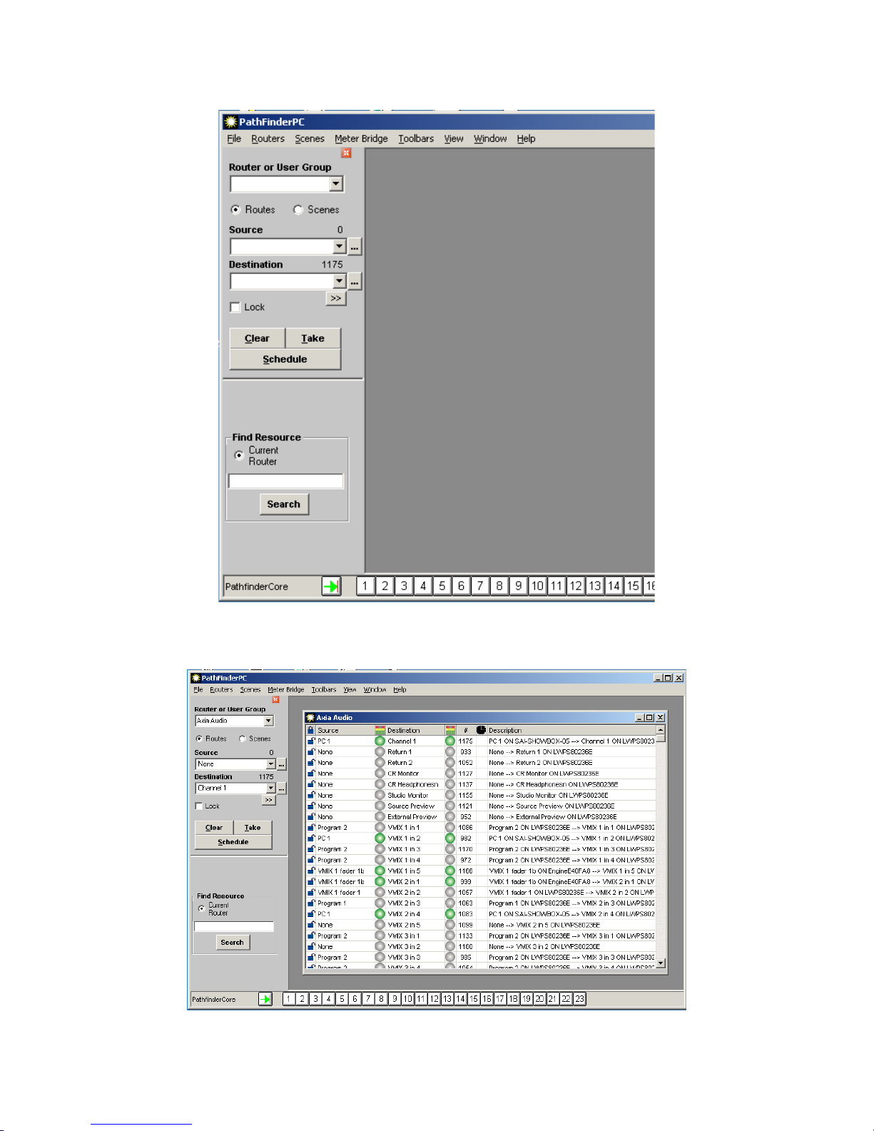
18: PathnderPC Client • 87
Under the Routers drop down list will be a list of all of the available Routers dened in Pathnder Core PRO.
Selecting any of these routers will bring up the appropriate routing list for that router.
© 2017 Telos Alliance - Rev 1.2
Page 97
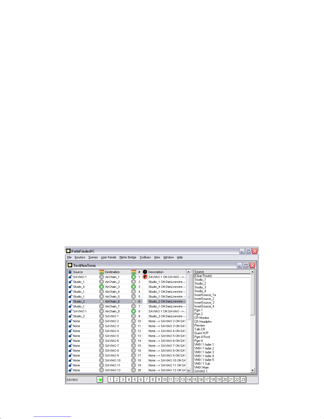
PathnderPC_Core has two control panel toolbars. Along the bottom is the window preset toolbar. Each
numerical button holds a window conguration. Since the user can have multiple router and meter windows open
simultaneously, this panel can be used to store these window positions and sizes for quick retrieval. Clicking on one
of the numerical buttons retrieves the window position and opens the correct windows, positioning them correctly.
In order to store a set of window positions, click the green arrow button and then the preset number into which you
wish to store the current window setup.
The route control toolbar is on the left side of the PathnderPC_Core screen. This provides the primary routing
control over the system. Routes may be made by selecting router and the destination, and then selecting the source
you wish to be assigned to the destination. Finally, click Take or clear to establish the route or clear the destination.
All source and destination drop down lists in the software can also display the description column by clicking on
the header row (top xed row) of the drop down list. Route points may also be locked or unlocked using this panel
if the router supports locking. Locked route points may not be taken by another user without specic conrmation.
Clicking on the padlock next to the line in the routing grid will also lock and unlock the point. When the padlock
is closed the point may not be changed unless it is unlocked rst. Clicking on a locked padlock to unlock the point
will produce a warning asking if you really wish to unlock the route point. There are some destinations that are
locked at the system level of the device and therefore cannot be unlocked or changed by PathnderPC_Core. These
include some Engine destinations that are involved in console operations. While PathnderPC_Core will display
the route status of these Engine Destinations, it is not allowed to make changes to their routing. That must be
accomplished through the standard Console and Engine interfaces, or through console control logic ows which
allow you to load different source or show proles.
Selecting the scene option changes the control panel to show a drop down list of scene changes which are available
for the chosen router. Any of these scenes may be selected and taken.
In addition, there are two other routing interfaces that may be selected depending on the user’s preference. For users
that prefer the legacy mode of routing, the route control toolbar may be closed. When this toolbar is closed, simply
clicking on the line for the appropriate destination and then clicking on the correct source in the pop-up list which
will appear on the right makes the route. Hitting escape closes the pop-up list without making a change.
18: PathnderPC Client • 88
© 2017 Telos Alliance - Rev 1.2
Page 98
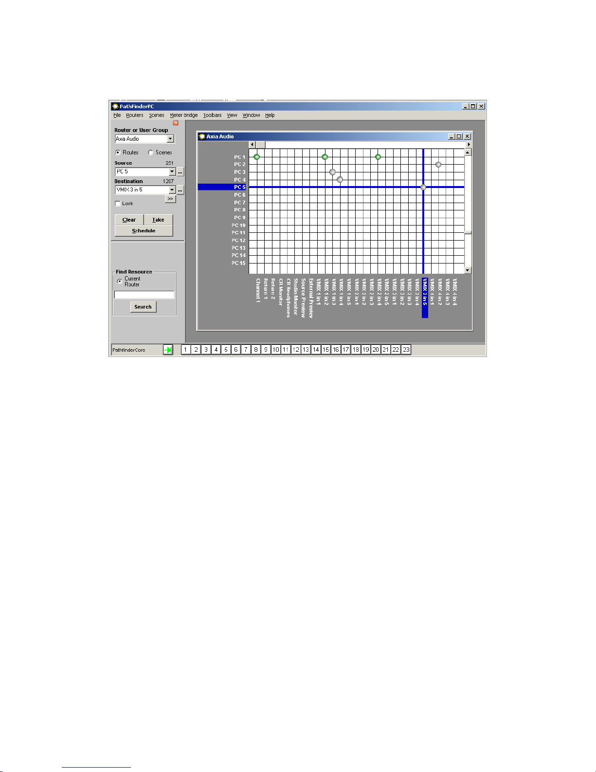
Finally, the user can select the Chart View under the view menu to produce a graphical grid view of the routing
status.
18: PathnderPC Client • 89
Selecting List under the view menu will return the routing status to the original mode.
Multiple routers may be open and arranged in the master parent window as desired.
The window menu allows the user to bring a particular window to the forefront or to arrange the windows
automatically within the parent window.
There are several columns in the routing grid. The lock icon shows whether the point is locked or unlocked. Next
is the name of the source name involved in the routing point. If the router is a Livewire Audio router, there will be
an audio icon which shows whether audio is present on the source. Next is the Destination name in the route point.
Again if the router is a Livewire Audio router, there will be an audio icon which shows whether audio is present on
the destination.
A green dot shows that audio is present. A red dot shows clipping, and a grey dot shows audio absent. If no dot is
present it signies that the route point does not support audio metering.
Next, there will be a column which shows the destination’s ordinal number in the router. The eye column shows the
status of any silence detection events. This column is not used by Pathnder Core PRO. But since the application
also works with PathnderPro, the column is still present. A blank eld means that the route point is not involved in
any silence detection. A “P” means that the route is connected to the “Primary” source. A “B” means that the route
is connected to the “Backup” source. An “F” means that the point has “Failed.” This could either be due to audio
failure on both primary and backup sources, or the current route is not set to either Primary or Backup. In addition,
these indicators will change from colored to grey to indicate the status has entered the pending timeout period and is
waiting the required timeout period before making a switch.
© 2017 Telos Alliance - Rev 1.2
Page 99
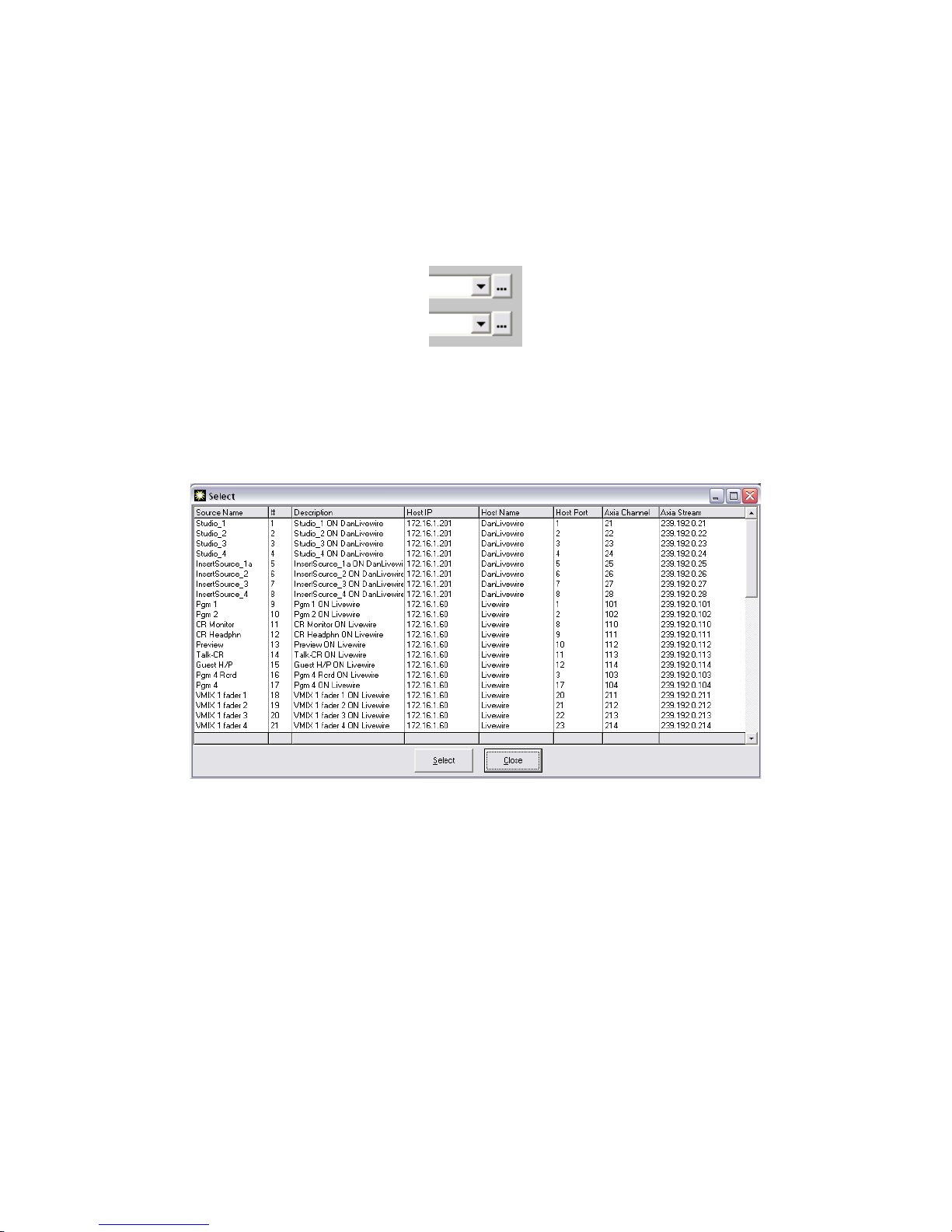
Finally, there is a column which shows the description eld. This is a combination of the description information
from both source and destination points.
Select List
Throughout the PathnderPC_Core Client software, there will be drop down lists when sources and destinations
need to be selected for events, stack events, route selections, etc. Next to these drop down lists will also be a button
identied by an ellipsis.
Clicking the ellipsis button will open a select window from which the source or destination may be selected as an
alternative to nding the point in the drop down list. This window includes a grid with additional information about
the sources or destinations including Name, Pathnder Number, Description, Host IP, Host Name, Axia Channel
Number, etc. The grid may be sorted by any of the columns and the columns may be resized and reordered.
Click the header bar with the column name for any column to sort the list by that column in ascending order. Click
the footer bar for the particular column to sort the list by that column in descending order. Dragging a column
header will allow you to reorder the columns. Press the Close button to close the window. Select the source or
destination in the list that you want applied to the drop down list in the previous window. Then click “select” or
double click the entry to select that entry and cause the select list to disappear. This process may be alternatively
used to select sources and destinations in the client wherever a drop down list is presented.
18: PathnderPC Client • 90
© 2017 Telos Alliance - Rev 1.2
Page 100
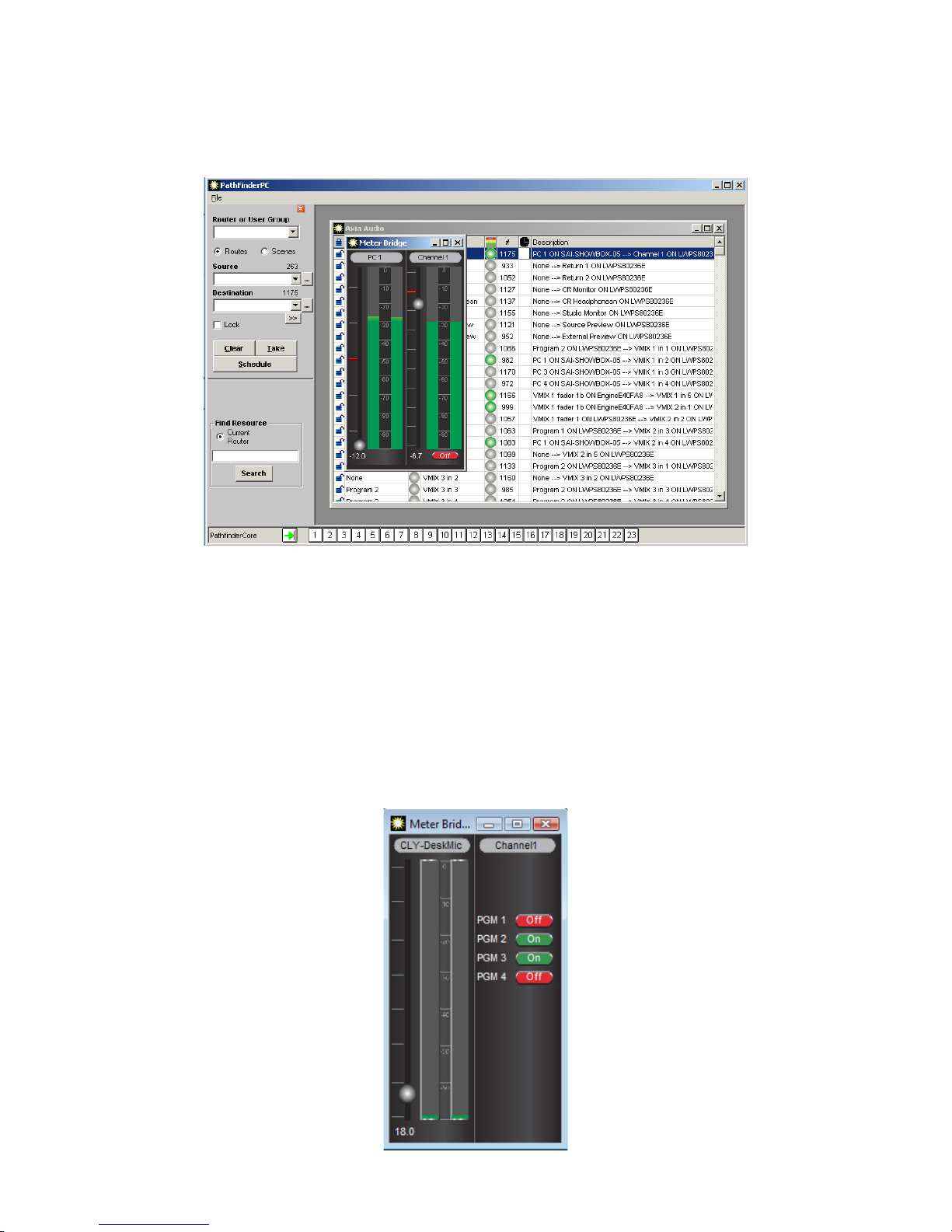
Metering
Right clicking on route points which support audio metering as indicated by the audio columns in the grid will open
a fully functional set of meters for that route point.
The meter bridge window may be enlarged and meters added, removed, and reorganized. Right clicking on the grid
will add additional meters to the meter bridge.
The meters may also have some additional controls depending on the type of source or destination they are
controlling. If the gain can be changed on the source or destination, a circular fader will be present next to the
meter which will allow these changes. If the IO is a node IO, this will change the gain on the node. If it is a Vmix,
it will change the Vmix fader gain. If it is a Console Fader Channel, it will change the actual level of the fader. In
addition, Vmix and Console Channels will present an On/Off button for turning the channel on or off. Finally, if
the destination is a Console Fader Channel, right clicking in the middle of the meter will cause the meter to show
program buss assignments which can also be changed.
18: PathnderPC Client • 91
© 2017 Telos Alliance - Rev 1.2
 Loading...