

Page 1
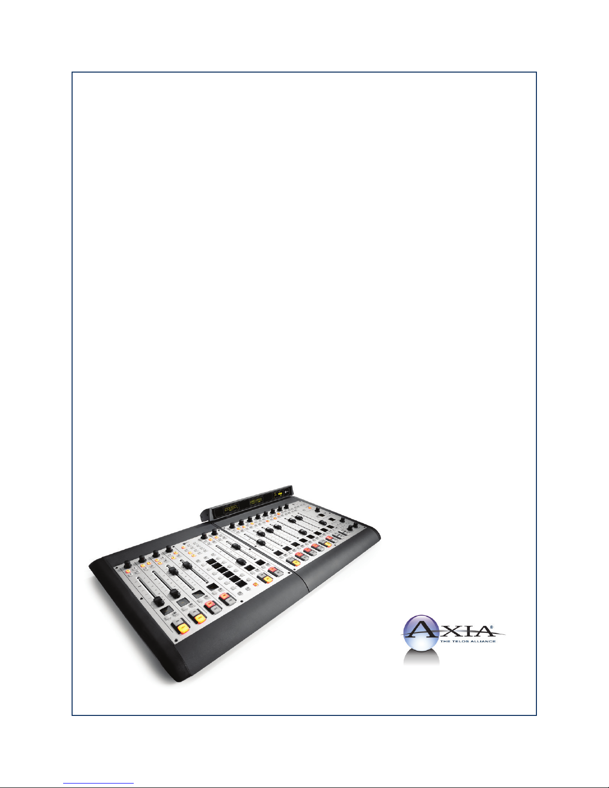
iQ Console System
Installation & User’s Guide
Manual Rev 1.3.1 — June, 2014
for iQ v1.00 and higher
p/n 1490-00067-001
Page 2

USA Class A Computing Device
Information To User. Warning:
This equipment generates, uses, and can radiate ra-
dio-frequency energy. If it is not installed and used
as directed by this manual, it may cause interference
to radio communication. This equipment complies
with the limits for a Class A computing device, as
specied by FCC Rules, Part 15, Subpart J, which
are designed to provide reasonable protection against
such interference when this type of equipment is op-
erated in a commercial environment. Operation of
this equipment in a residential area is likely to cause
interference. If it does, the user will be required to
eliminate the interference at the user’s expense.
Important Safety Information
To prevent risk of electric shock: Disconnect power
cord before servicing. If fuse replacement is required,
please note: For continued protection against re, re-
place fuse only with same type and value.
Caution
The installation and servicing instructions in the
manual are for use by qualied personnel only. To
avoid Electric Shock, do not perform any servicing
other than that contained in the operating instruc-
tions unless you are qualied to do so. Refer all ser-
vicing to qualied personnel.
NOTE: Objectionable interference to TV or radio re-
ception can occur if other devices are connected to
this device without the use of shielded interconnect
cables. FCC rules require the use of only shielded
cables.
Canada Warning:
“This digital apparatus does not exceed the Class A
limits for radio noise emissions set out in the Radio
Interference Regulations of the Canadian Depart-
ment of Communications.” “Le present appareil
numeriQue n’emet pas de bruits radioelectriQues
depassant les limites applicables aux appareils nu-
meriQues (de les Class A) prescrites dans le Regle-
ment sur le brouillage radioelectriQue edicte par le
ministere des Communications du Canada.”
CE Conformance Information:
This device complies with the requirements of the
EEC Council Directives: 93/68/EEC (CE Marking);
73/23/EEC (Safety – low voltage directive); 89/336/
EEC (electromagnetic compatibility). Conformity is
declared to those standards: EN50081-1, EN50082-1.
Electrical Warning
To reduce the risk of electrical shock, do not expose
this product to rain or moisture. Keep liquids away
from the ventilation openings in the top and rear of
the unit. Do not shower or bathe with the unit.
This equipment is designed to be operated from a
power source that includes a third “grounding” con-
nection in addition to the power leads. Do not defeat
this safety feature. In addition to creating a potential-
ly hazardous situation, defeating this safety ground
will prevent the internal line noise lter from func-
tioning.
Ventilation Warning
The Axia QOR.32 requires the free ow of air for
adequate cooling. Do not block the ventilation open-
ings in the top and rear of the unit. QOR.32 must be
mounted with a blank rack space above or damage
may occur.
Failure to allow proper ventilation could damage the
unit or create a re hazard. Do not place the units on
a carpet, bedding, or other materials that could inter-
fere with any panel ventilation openings.
Page 3

Customer Service
We support you...
By Phone/Fax.
• You may reach our 24/7 Support Team anytime around the clock by calling +1 216-622-0247. For billing
questions or other non-emergency technical questions, call +1 216-241-7225 between 9:30 AM to 6:00 PM
USA Eastern Time, Monday through Friday.
By E-Mail.
• Non-emergency technical support is available at [email protected].
Via World Wide Web.
• The Axia Web site has a variety of information which may be useful for product selection and support. The
URL is http://www.AxiaAudio.com.
Feedback
We welcome feedback on any aspect of the Livewire products or this manual. In the past, many good ideas from
users have made their way into software revisions or new products. Please contact us with your comments.
Updates
The operations of iQ and QOR.32 are determined largely by software. Periodic updates may become available -
to determine if this is the case, visit our web site periodically, or contact us for advice concerning whether a newer
release is more suitable to your needs.
We recommend joining the Axia Tech mailing list to ensure that you receive immediate updates regarding
new software or documentation releases. You can do so by clicking the “Sign Up Here” links at the top of the
Axia Download and Manuals pages at AxiaAudio.com/manuals/ and AxiaAudio.com/downloads/.
Trade mark s
Livewire is a trademark of TLS Corporation. All other trademarks are the property of their respective holders.
Axia Audio
1241 Superior Ave. Cleveland, OH 44114 USA
+1 (216) 241-7225
Copyright © 2014 by TLS Corporation. Published by Axia Audio. We reserve the right to make improvements or changes in the pr od-
ucts described in this manual, which may affect the product specications, or to revise the manual without notice. All rights reserved.
© 2014 Axia Audio - Rev 1.3.1
Introduction • iii
Page 4

Notice
Feedback is welcome
Introduction • iv
All versions, claims of compatibility, trademarks, etc.
of hardware and software products not made by Axia
mentioned in this manual or accompanying material
are informational only. Axia makes no endorsement
of any particular product for any purpose, nor claims
any responsibility for operation or accuracy.
Warranty
This product is covered by a Two Year limited war-
ranty, the full text of which is included in the rear
section of this manual.
Service
You must contact Axia before returning any equip-
ment for factory service. Axia will issue a Return
Authorization number, which must be written on the
exterior of your shipping container. Please do not
include cables or accessories unless specically re-
quested by the Technical Support Engineer at Axia.
Be sure to adequately insure your shipment for its
replacement value. Packages without proper authori-
zation may be refused. US customers please contact
Axia technical support at +1 (216) 241-7225. All oth-
er customers should contact their local representative
to arrange for service.
We strongly recommend being near the unit when
you call, so our Support Engineers can verify infor-
mation about your conguration and the conditions
under which the problem occurs. If the unit must
return to Axia, we will need your serial number, lo-
cated on the rear panel.
Credit Where Credit’s Due
Thanks to the great folks on the Axia team who
produced a great product and helped to compile this
manual - Denny, Gints, Maciej, Marc, Maris, Mar ty,
Milos, Oleg — we are honored to work with all of
you. cn and bw.
At Axia, we love to hear your feedback. If you nd
anything in this manual that you feel needs clarica-
tion or correction, please let us know by sending an
e-mail to [email protected] .
About This Manual
This manual covers the details of the iQ Frames
and QOR.32. Axia’s iQ is designed to operate as a
standalone console however it also has network ca-
pabilities. To learn more about these concepts, you
may wish to read Introduction to Livewire: System
Design Reference and Primer and Audio Over IP:
Building Pro AoIP Systems with Livewire by Steve
Church and Skip Pizzi, available from Elsevier Press.
In these publications we explain the ideas that mo-
tivated Livewire and how you can use and benet
from it, as well as nitty-gritty details about wiring,
connectors, and the like. Since Livewire is built on
standard networks, we also help you to understand
general network engineering so that you have the full
background for Livewire’s fundamentals. After read-
ing this reference material, you will know what’s up
when you are speaking with the network guys that
are often hanging around radio stations these days.
Although we strive for accuracy, some features and
operational characteristics may differ in actual use
from their descriptions herein. We invite feedback
and corrections from our clients.
Axia Audio
1241 Superior Avenue
Cleveland Ohio 44114 USA
Ph one: +1.216.241.7225
Web: www.AxiaAudio.com
E-Mail: [email protected]
© 2014 Axia Audio - Rev 1.3.1
Page 5

Table of Contents
Customer Service . . . . . . . . . . . . . . . . . .iii
Warranty . . . . . . . . . . . . . . . . . . . . . . iv
Service . . . . . . . . . . . . . . . . . . . . . . . iv
Credit Where Credit’s Due . . . . . . . . . . . . .iv
About This Manual . . . . . . . . . . . . . . . . . iv
A Note From The CEO of Telos. . . . . . . . . . .vii
Getting Started . . . . . . . . . . . . . . . . . . . . . . 1
Preview Mode . . . . . . . . . . . . . . . . . . 15
Preview Switching. . . . . . . . . . . . . . . .15
Auto-Start Timer. . . . . . . . . . . . . . . . .15
Logic Port . . . . . . . . . . . . . . . . . . . 16
Feed to Source. . . . . . . . . . . . . . . . . .16
Feed to Source Dim Gain . . . . . . . . . . . . 16
Live Controls . . . . . . . . . . . . . . . . . . 17
iQ Outputs . . . . . . . . . . . . . . . . . . . . . . .17
V-Mixer and V-Mode . . . . . . . . . . . . . . . . . 18
Adding Backfeeds and GPIO . . . . . . . . . . . . .19
Chapter One: Setup And Connections . . . . . . . . . 3
Introduction . . . . . . . . . . . . . . . . . . . . . . 3
The Basics . . . . . . . . . . . . . . . . . . . .3
Assigning an IP Address. . . . . . . . . . . . .3
Notes on Physical Installation . . . . . . . . . 3
QOR.32: Front Panel . . . . . . . . . . . . . . . . .4
Front Panel Indicators . . . . . . . . . . . . . . . 4
QOR.32: Rear Panel. . . . . . . . . . . . . . . . . .5
Power. . . . . . . . . . . . . . . . . . . . . . . .5
Audio Connections . . . . . . . . . . . . . . . . . 6
GPIO Connections . . . . . . . . . . . . . . . . . 7
Ethernet Connections. . . . . . . . . . . . . . . .7
iQ Frame and CANBus Connections. . . . . . . .7
IP Address Conguration. . . . . . . . . . . . . .8
Console Conguration . . . . . . . . . . . . . . . 9
Chapter Two: Inputs and Outputs . . . . . . . . . . . 11
Inputs . . . . . . . . . . . . . . . . . . . . . . . . . 11
What’s a Prole? . . . . . . . . . . . . . . . . . . . 12
Show Proles . . . . . . . . . . . . . . . . . . . .12
Source Proles . . . . . . . . . . . . . . . . . . . 12
Source Conguration . . . . . . . . . . . . . . . 12
Creating a New Source . . . . . . . . . . . . . 13
Source Type . . . . . . . . . . . . . . . . . . . 13
Source Input. . . . . . . . . . . . . . . . . . .14
Primary Source . . . . . . . . . . . . . . . . . 14
Signal Mode (Non-Microphone Sources) . . . . 14
Signal Phase (Non-Microphone Sources). . . .14
Record Mode . . . . . . . . . . . . . . . . . . 14
Fader Trim Gain . . . . . . . . . . . . . . . . 14
Equalizer . . . . . . . . . . . . . . . . . . . . 14
Panorama Position . . . . . . . . . . . . . . . 15
Source Availability . . . . . . . . . . . . . . . 15
Fader Mode . . . . . . . . . . . . . . . . . . . 15
Chapter Three: Console Operation. . . . . . . . . . .21
Overview . . . . . . . . . . . . . . . . . . . . . . . 21
Displays . . . . . . . . . . . . . . . . . . . . .
Show Proles . . . . . . . . . . . . . . . . . . 21
Sources, Channels and Faders . . . . . . . . . 21
Mix-Minus . . . . . . . . . . . . . . . . . . . .21
GPIO . . . . . . . . . . . . . . . . . . . . . . 22
Software . . . . . . . . . . . . . . . . . . . . .22
iQ Main Frame - Callouts and Operation . . . . . 22
System Settings . . . . . . . . . . . . . . . . . 27
iQ 8-Fader Expansion Frame . . . . . . . . . . . 27
iQ 6-Fader+Telco Expansion Frame . . . . . . . 27
iQ 6-Fader+User Keys Expansion Frame . . . . .29
Source-Specic Channel Controls. . . . . . . . . . .29
Control Room Operator Mic Channel . . . . . 29
Producer Microphone Channel . . . . . . . . . 29
Control Room Guest Microphone Channel . . . 29
Studio Microphone Channel . . . . . . . . . . 30
External Microphone Channel . . . . . . . . . 30
Phone Channel . . . . . . . . . . . . . . . . . 30
Codec Channel . . . . . . . . . . . . . . . . . 30
Remote Control . . . . . . . . . . . . . . . . . 31
Chapter Four: Show Proles . . . . . . . . . . . . . . 33
Creating A Show Prole. . . . . . . . . . . . . . . .33
Show Prole Options . . . . . . . . . . . . . . . . . 34
Chapter Five: Conguring GPIO . . . . . . . . . . . .39
GPIO Port Denitions . . . . . . . . . . . . . . . . .39
GPIO Operator’s Microphone Logic. . . . . . . .40
GPIO Control Room Guest Microphone Logic . . 41
GPIO Studio (Monitor 2) Guest Microphone Logic 42
GPIO Producer’s Microphone Logic. . . . . . . .43
GPIO Line Input Logic . . . . . . . . . . . . . . .44
21
Introduction • v
© 2014 Axia Audio - Rev 1.3.1
Page 6

GPIO Codec Logic . . . . . . . . . . . . . . . . . 45
GPIO Telephone Hybrid Logic . . . . . . . . . . .46
GPIO Control Room Monitor Logic . . . . . . . . 47
GPIO Studio Monitor Logic . . . . . . . . . . . . 48
GPIO Computer Playback Device Logic. . . . . .49
GPIO Film Legendable User Button Module / Acces-
sory Panel / Rack Panel . . . . . . . . . . . . . .
GPIO Recording Device Logic. . . . . . . . . . .51
Assigning GPIO to a Source. . . . . . . . . . . . . .52
Connections to GPIO Ports . . . . . . . . . . . . . . 53
Input Connections . . . . . . . . . . . . . . . . .
Output Connections . . . . . . . . . . . . . . . . 54
Virtual GPIO . . . . . . . . . . . . . . . . . . . . 54
Conguring and using iQ User Keys . . . . . . . . . 55
Chapter Six: Advanced Controls . . . . . . . . . . . . 57
iQ Conguration Screens . . . . . . . . . . . . . . . 57
The iQ Control Center . . . . . . . . . . . . . . . 57
The Status Screen . . . . . . . . . . . . . . . . 57
The Setup Menu . . . . . . . . . . . . . . . . . 57
The Customize Menu . . . . . . . . . . . . . . 58
Log, Log History and Log Setup Menus . . . . 59
Brightness Control Menu . . . . . . . . . . . . 60
User Modules Menu. . . . . . . . . . . . . . .60
GPIO Conguration Menu . . . . . . . . . . . 60
Remote. . . . . . . . . . . . . . . . . . . . . .60
Prole Manager Menu . . . . . . . . . . . . . 61
IO Manager Menu. . . . . . . . . . . . . . . .61
Ethernet Switch settings (Precongured) . . . . 61
50
53
Chapter Seven: Networking with iQ . . . . . . . . . . 63
Inputs . . . . . . . . . . . . . . . . . . . . . . . . . 63
Outputs . . . . . . . . . . . . . . . . . . . . . . . . 64
GPIO. . . . . . . . . . . . . . . . . . . . . . . . . .65
Networking . . . . . . . . . . . . . . . . . . . . . . 65
Appendix A: iQ Specications . . . . . . . . . . . . . 67
Table of Inputs and Outputs . . . . . . . . . . . . . 68
Appendix B: iQ Block Diagrams . . . . . . . . . . . . 73
Appendix C: Channel / IP Worksheets . . . . . . . . . 81
Warranty . . . . . . . . . . . . . . . . . . . . . . . . . 85
Introduction • vi
© 2014 Axia Audio - Rev 1.3.1
Page 7

A Note From The Vice President of Axia
2013 marks a banner year for Axia — this year
marks the rst decade of the Connected Studio.
In retrospect, it’s hard to believe it’s been 10 years
since a start-up division of Telos grabbed everyone’s
attention with a radical idea about building radio stu-
dios using Ethernet. At a time when “state of the art”
meant discrete digital audio, and a routing switcher
was something only the richest stations could af-
ford, Axia shocked everyone with the idea that studio
peripherals from the console to the audio processor
could be networked, and that everyone could have the
benets of a routing switcher — for about a third of
the cost of traditional technology.
When we launched Axia, Telos founder Steve
Church made a prediction. “Three things will hap-
pen,” Steve told us. “First, people will say that ‘it will
never work.’ When they’re proven wrong, they’ll say
‘It works, but you don’t need that.’ And nally, as they
see Axia becoming successful, they’ll say ‘IP-Audio?
We do that too!’”
Steve, as always, was right on the money. In 10
years, Axia Livewire has become the world’s most
popular IP-Audio networking technology, and our
mixing consoles are the world’s best-selling — they’re
on-air in over 4,000 studios, and counting. You’ll nd
Axia equipment everywhere: at privately-owned sta-
tions, and large clusters run by big conglomerates. At
established public broadcasters, and at newly-licensed
International stations. At government broadcast facili-
ties, and podcast studios. Needless to say, we’re hum-
bled by the trust broadcasters place in us — and by
your enthusiasm!
of IP-Audio. Axia consoles are the rst and only IP-
Audio consoles with a pre-congured network switch
built in, to save broadcasters the effort and expense
of procuring and programming third-party switches.
Our compact xNode AoIP interfaces feature one-but-
ton setup, and can run on mains power or Power over
Ethernet (PoE) for exibility and redundancy. We’ve
even developed our own zero-conguration Ethernet
switch for Livewire – xSwitch – to make deploying
IP-Audio easier than ever.
More than 45 Livewire partners believe in the vi-
sion of the Connected Studio too. Collectively, they
make dozens of hardware and software products
(ranging from telephone systems to audio processors
to program automation) that interoperate directly with
Axia networks via Ethernet – making the connec-
tions “smart”, and eliminating the need to purchase
audio conversion devices. We’ve also partnered with
the high-performance audio standard RAVENNA to
expand broadcasters’ networking options even further.
And there are a lot more great new ideas in the cooker
— so watch this space!
In the nal analysis, Axia’s success isn’t due to
our efforts. It’s you, the broadcast professional, who
has embraced our vision, used our technology in ways
we never dreamed of, and raved about Axia products
to everyone who’d listen. We owe you a huge debt of
thanks. And we promise to never stop trying to amaze
and delight you.
So here’s to the next 10 years.
Onward and upward!
Being rst with new technology is nice, but we’ve
never been content to rest on our laurels. So the Telos
R&D team continues to innovate and expand the scope
Marty Sacks
Vice President, Axia Audio
Introduction • vii
© 2014 Axia Audio - Rev 1.3.1
Page 8

CAT.6, m n ig
n n dt r rt.
Wh ag s ts?.
Introduction • viii
© 2014 Axia Audio - Rev 1.3.1
Page 9
Getting Started
The following chapters of this manual will give you
an in-depth understanding of the capabilities of your
new iQ fader frames and QOR.32, from installation to
advanced functions. This section will help you get ev-
erything connected quickly, and point you to the parts
of the manual you’ll need to get up and running with a
minimum of fuss.
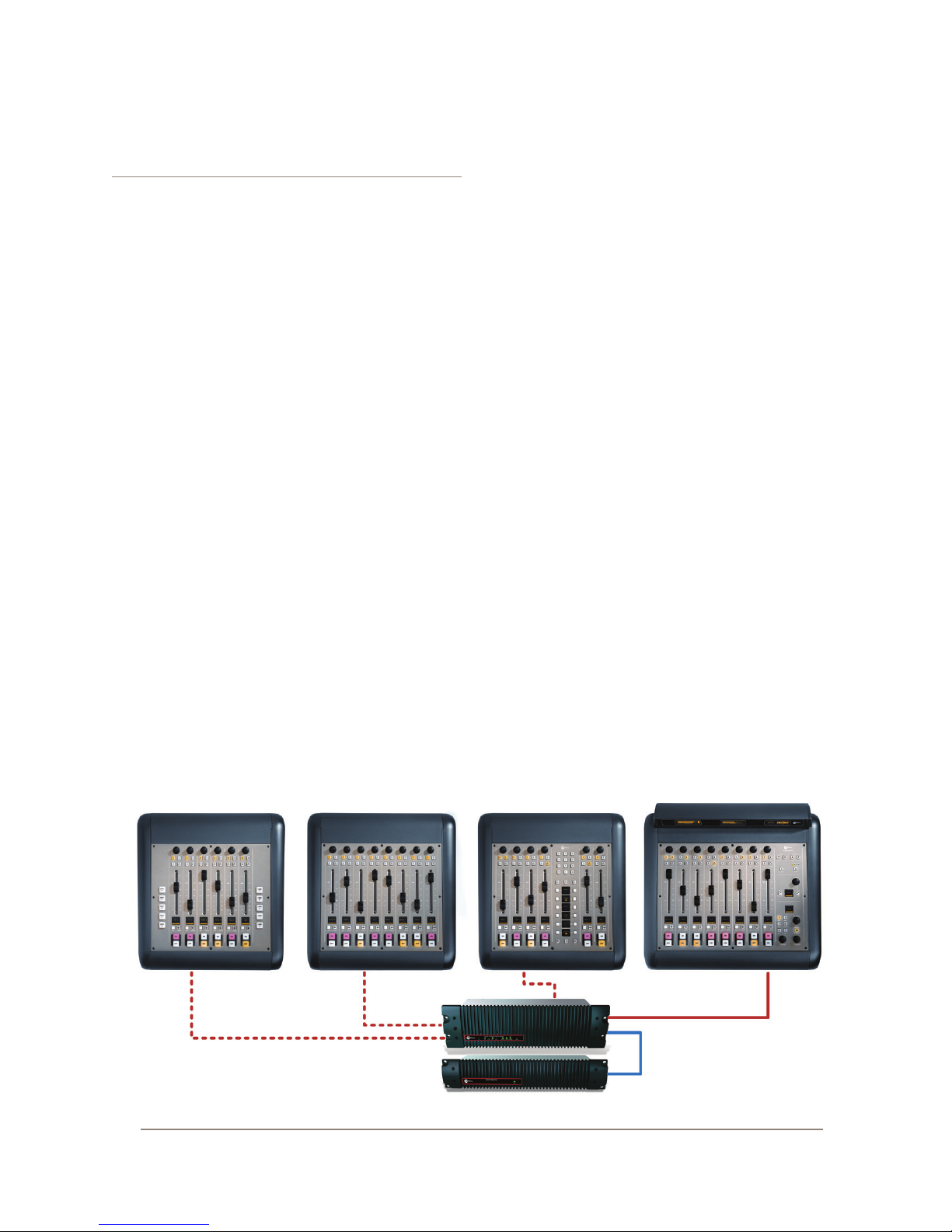
The Axia iQ family consists of these components:
• iQ Main Frame: 8-fader frame with master con-
trols and meters.
• iQ 8-Fader Frame: 8-fader expansion frame
• iQ 6-Fader+User Keys: Optional expansion
frame includes 6 faders and two banks of pro-
grammable user keys.
• iQ 6-Fader+Telco: Optional expansion frame
includes 6 faders and a Telos-style dual channel
hybrid controller.
• QOR.32: Rack-mounted CPU chassis with au-
dio I/O and GPIO connectors.
• QOR Backup Power Supply: Optional rack-
mounted backup power supply.
Making Connections
You’ve probably unpacked your boxes and are sitting
next to a pile of Axia gear, wondering what to do rst.
Here’s what you need to know in order to get started:
1. Packed with each of your iQ Frames is a cable
with 6-pin Molex™ connectors on each end. This is
the power/communications cable. Connect the end of
the cable without the strain relief to the correspond-
ing port on the iQ Frame connection panel. Connect
the other end of the cable to one of the connectors
labeled CONSOLE on the back of your QOR.32 unit.
You can use a maximum of three iQ Frames with
each QOR.32. One must be an iQ Main Frame.
2. Connect all iQ audio sources (microphones,
CD players, etc) to inputs of your QOR.32.
3. Connect monitor ampliers, headphone ampli-
ers, etc to outputs of your QOR.32. Be sure to set all
ampliers to their minimum volume setting.
4. Follow the instructions found in Chapter 1 to
congure IP address settings for the QOR.32.
5. Refer to the User’s Manuals packed with any
other Axia Audio Nodes for information on how to
congure IP addresses for these units.
What’s Next?
When you’ve completed physically connecting your
Axia hardware, jump to Chapter 2 for a quick tutorial
on conguring audio sources. With that done, you’ll be
a hop, skip, jump away from being on-air! After that,
you’ll likely want to do some in-depth reading about all
The iQ Family: (top L-R) iQ 6-Fader, iQ 8-Fader, iQ Phone, iQ Main Frame, (bottom) QOR.32 and QOR Backup PSU
Getting Started • 1
© 2014 Axia Audio - Rev 1.3.1
Page 10

your new iQ can do. Here’s a brief description of the con-
tents of the following chapters:
• Chapter 1: iQ Frames and QOR.32 explains con-
nections and basic iQ setup.
• Chapter 2: iQ Inputs and Outputs explains how to
generate Source Proles and construct backfeeds for
selected sources.
• Chapter 3: iQ Operations takes you behind the
scenes to explore operator controls and options.
• Chapter 4:Show Proles illustrates how to set and
save unique “snapshots” tailored for specic shows.
These Show Proles can be instantly recalled when-
ever needed.
• Chapter 5: GPIO tells how to associate routable
logic commands with any audio source.
• Chapter 6: Advanced iQ Controls discusses ad-
vanced features that are congured in the iQ con-
guration web pages.
• Chapter 7: Livewire Networking and iQ will tell
you how to connect your iQ to a network and reap the
benets of networked studio systems.
• Appendices provide additional technical specica-
tions and a complete set of block diagrams for your
reference.
Read on. Enjoy your iQ.
Stay up to date! We recommend joining the
Axia Tech mailing list to ensure that you receive
immediate updates regarding new software or
documentation releases. You can do this by
clicking the “Sign Up Here” link at the top of
AxiaAudio.com/manuals/ & AxiaAudio.com/downloads/.
Getting Started • 2
© 2014 Axia Audio - Rev 1.3.1
Page 11

Chapter One:
Setup and Connections
Introduction
If you are reading this manual, you are probably the
proud owner of a new iQ console. You’ve read the Get-
ting Started section, are probably already passing audio,
and are hungry for more knowledge. Here we go!
The Basics
iQ was designed to get you on the air as quickly as
possible with the least amount of effort. It’s the perfect
standalone radio console (and it even networks, too - see
Chapter 7: Livewire Networking and iQ for details on
how to do that).
This chapter covers connecting iQ to your other stu-
dio gear, such as microphones, CD players and other au-
dio playback devices. The audio outputs of the QOR.32
connect to control room monitors, preview (cue) speak-
er, headphones ampliers and audio recording devices.
These external audio devices may be analog or AES de-
vices.
The GPIO (General Purpose Input Output) ports pro-
vide logic control interfaces to devices such as air lights,
recorders and CD players.
The 100 Mbps Ethernet ports may be used to con-
nect PCs running Axia’s IP-Audio driver, to expand your
system by adding other Livewire devices such as Axia
Audio Nodes, or equipment from Axia Partners (see
AxiaAudio.com/partners/ for the latest list of companies
whose equipment connects directly to Axia networks).
1000 Mbps (Gigabit) Ethernet ports are used to con-
nect to other QOR.32 units or an Ethernet core switch
— another topic covered in Chapter 7.
6-pin Molex connectors are used to connect your iQ
Main, iQ Frames (max of 3 including Main) and CAN-
Bus accessory panels. A single cable from each Frame
will be used to connect it to the QOR.32. Each iQ Frame
must have a dedicated Console port. Accessory modules
can be daisy-chained from the CANBus Accessory port.
The D-sub combo connector connects ONLY to your
optional QOR Backup power supply. The IEC receptacle
is for your A.C. mains power connection.
Assigning an IP Address
Before you can congure your iQ hardware, you’ll
need to assign it an IP address. Press-and-hold the Meter
and Clock keys for three seconds. The Studio display
now shows the options and the Studio Monitor control is
used to navigate, select IP Address options and change
parameter values. Consult your network administrator if
you are unsure about what address to use.
Each iQ system requires a single, xed IP address.
The iQ Frames are controllers for the QOR.32 engine
and they share the same IP addresses. If the iQ is stand-
alone, the default IP address will probably be ne. See
Chapter 7 for more details when multiple iQ’s are used
or when your iQ is a part of a larger network.
Notes on Physical Installation
The QOR.32 is fan-free, so it can be located in any
studio without fear of unwanted noise. Those vents and
heat sinks serve a very important purpose! Be sure to
mount the QOR in an equipment rack with free air ow.
We recommend using a ventilated 1RU rack spacer
above and below the QOR.32 to ensure adequate ven-
tilation.
To install the iQ Frames in your studio, all you need
is a desk — no console cutout required. You may also
rack-mount your iQ Main Frame using the included
rack-mount hardware. This same hardware serves dou-
ble duty to join your iQ Frames together if you prefer
one, continuous console rather than individual units.
To join iQ console sections:
Remove the adjacent side bezels of the iQ Frames
that you wish to join and attach both rack-mount anges
to one of the frames as illustrated on the next page.
1: Setup and Connections • 3
© 2014 Axia Audio - Rev 1.3.1
Page 12
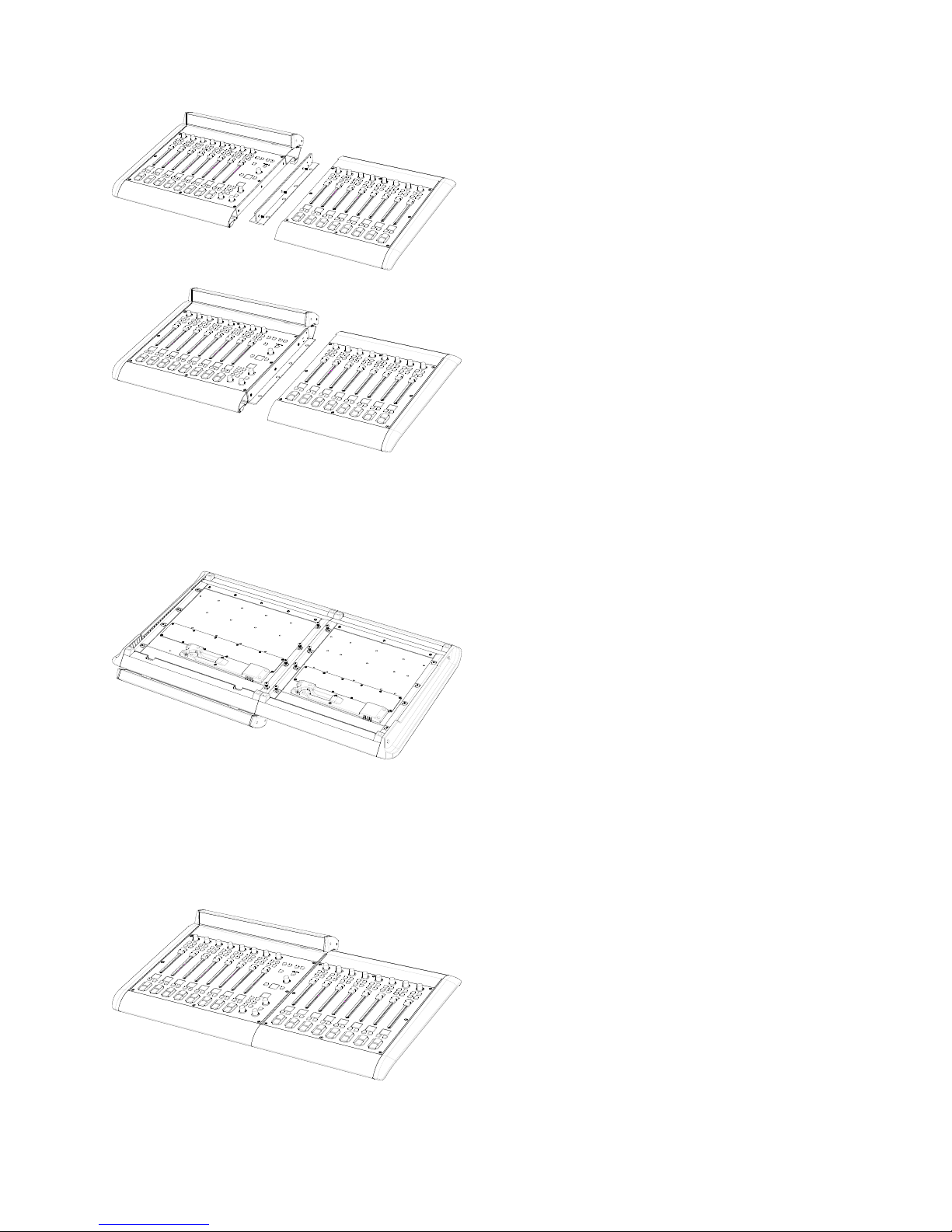
Flip the iQ frames over and use the rack-mount
screws to securely attach the rack-mount anges to the
underside of the iQ Frames.
QOR.32: Front Panel
The indicator panel of the QOR.32, shown on the
following page, is very simple. There are no controls
for you to push or turn. Conguration and setup is per-
formed from the console itself or through the iQ web
browser interface.
Front Panel Indicators
Even though there are no knobs or dials, the front
panel has some very useful indicators that tell you about
the health and status of your QOR.32. In all cases, solid
GREEN indicates normal operating conditions.
CHECK
This is a general health indicator for the QOR.32. If
this indicator is RED, immediately check the web pages
for abnormal operating conditions such as excessive
CPU temperature. Do not ignore this indicator. Note that
it is normal for this indicator to ash during boot-up.
1: Setup and Connections • 4
The physical arrangement of the frames is complete-
ly arbitrary. The channel assignments are determined by
the iQ Main port to which you connect each iQ frame.
LIVEWIRE
When lit, indicates that Livewire channels are being
taken from the network. If no network sources are being
received, this indicator is not illuminated.
SYNC
If your iQ is part of a larger network, a solid GREEN
indicates the QOR.32 is synchronized as a slave to the
Livewire network and that its internal clock is locked.
Flashing GREEN indicates that sync packets are being
received, but that iQ is not yet locked. It is normal for the
SYNC indicator to ash for several seconds at startup. If
it does not “lock” with a solid, non-ashing LED, this
may indicate an incorrectly congured network switch.
Check your Ethernet switch conguration or call Axia
24/7 Support for assistance.
MASTER
Solid GREEN indicates the QOR.32 is synchronized
as a Master clock to the Livewire network. This indi-
cator will always be green for a standalone console. If
you have any other Livewire devices, they should be re-
porting Sync or Slave. There should be only one Master
clock device in a Livewire network at any given time.
© 2014 Axia Audio - Rev 1.3.1
Page 13
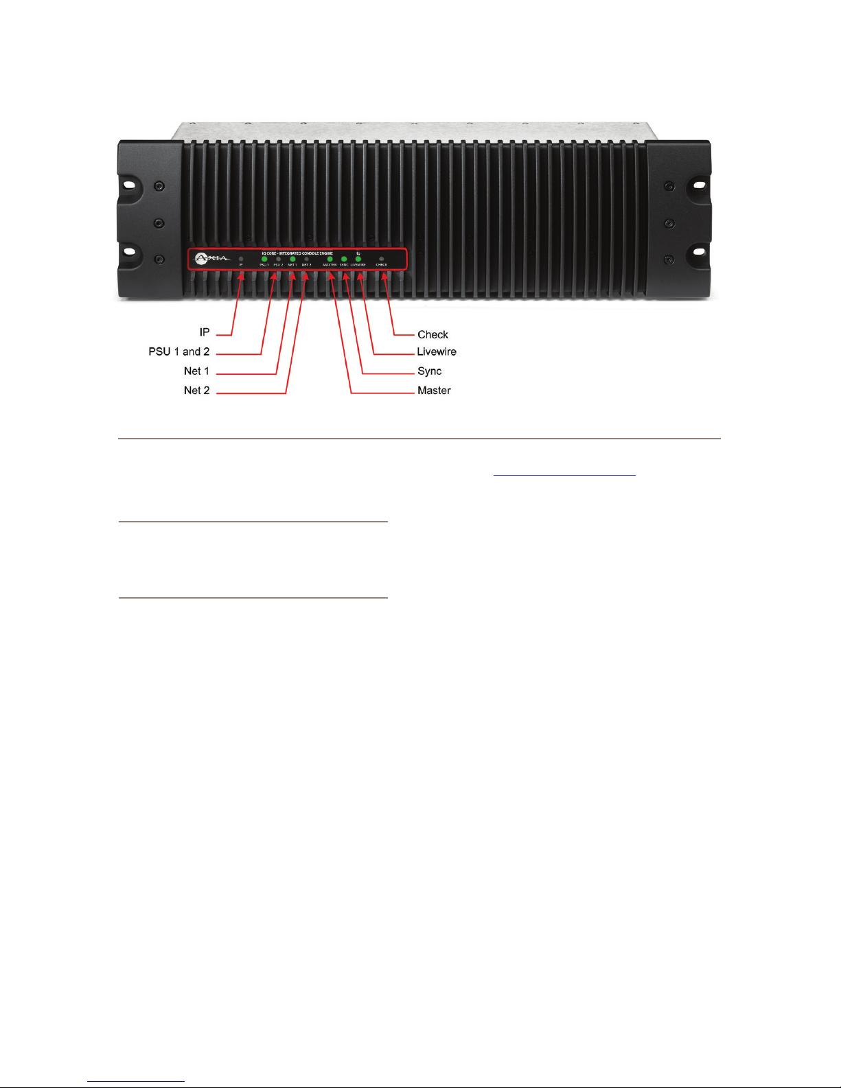
Figure 1-1: QOR.32 - Front Panel
Figure 1-1 shows both Master and Sync illuminated for
illustration purposes only.
Note: The MASTER and SYNC indicators are not
normally ON at the same time since the QOR.32
will be either a Master or Slave. This principle
applies to all Axia Livewire devices. Any Livewire
network will have only a single Master.
NET 1 and NET 2
These indicators provide the status of the two 1000
Mbsec (Gigabit) NICs in the QOR.32. Note that the unit
can be used with either or both ports connected to prop-
erly congured Ethernet switches or other QOR.32 units.
When the Gig1 or Gig2 ports have active connec-
tions, the NET1 or NET2 lamps (respectively) will illu-
minate. If a network cable is connected to a Gig port and
the corresponding NET lamp is unlit, a problem with the
network connection is indicated.
When a disconnected Ethernet link has been re-estab-
lished, the NET LED will blink with a 50% duty cycle
for about 5 seconds as the network activity is resumed.
Please consult Axia’s Ethernet switch conguration
guides for details when using Core switches in a larger
network. Ethernet Switch guides may be found on our
web site at AxiaAudio.com/manuals/.
PSU
There are two PSU indicators providing assurance
that the QOR.32 power supply rails are normal. Solid
GREEN indicates normal power supply status.
The PSU2 indicator is active only when am QOR
Backup is present and when the iQ console is congured
to incorporate the QOR Backup.
IP
This indicator will illuminate upon detection of an
external Ethernet core switch connected to the QOR.
QOR.32: Rear Panel
Power
• AC Mains: There is one standard IEC receptacle for
your mains power for voltages in the range from 100
to 240 VAC at either 50 or 60 Hz.
• PSU2 (Backup): This is a D-sub combo connector
for use only with the QOR Backup 48 VDC power
supply. Connect your optional backup power supply
with the provided cable.
1: Setup and Connections • 5
© 2014 Axia Audio - Rev 1.3.1
Page 14
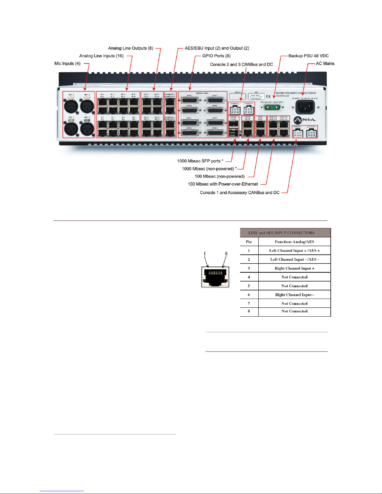
1: Setup and Connections • 6
Figure 1-2: QOR.32 - Rear Panel Conne ctions
Audio Connections
The QOR.32’s rear panel contains all of the connec-
tors used for audio I/O, Ethernet, GPIO, power supply
and the connections to your iQ frames. Note that we use
RJ-45 connectors for three purposes:
• Analog audio inputs and outputs
• AES audio inputs and outputs
• Ethernet (some with PoE - Power over Ethernet)
It is important to follow the proper conventions for
wiring these connectors and ensure that the connector
functions are not confused as damage may result if you
plug a network cable into an audio input.
Analog and AES Audio
The connector pin functions shown in Figure 1-3 are
the same for both the AES and Analog inputs and out-
puts.
The nominal audio level for analog line inputs and
outputs is +4 dBm. This audio level will provide you
with 20 dB of headroom.
Note: The well-labelled RJ-45 connectors on
the QOR.32 rear panel are used for different
Figure 1-3: RJ-45 Audio Connector Pinouts
functions. Be sure to use them only for their intended purpose as described in this section.
Microphone Inputs
There are four XLR-F connectors on the rear panel
for connection of microphone inputs. These connectors
use the standard wiring convention for 3-pin XLR audio
connectors. These connectors may have 48-volt Phan-
tom power enabled via the QOR.32’s web page congu-
ration. Please take appropriate precautions if you con-
nect anything other than a microphone to these inputs
when Phantom power is enabled.
© 2014 Axia Audio - Rev 1.3.1
Page 15
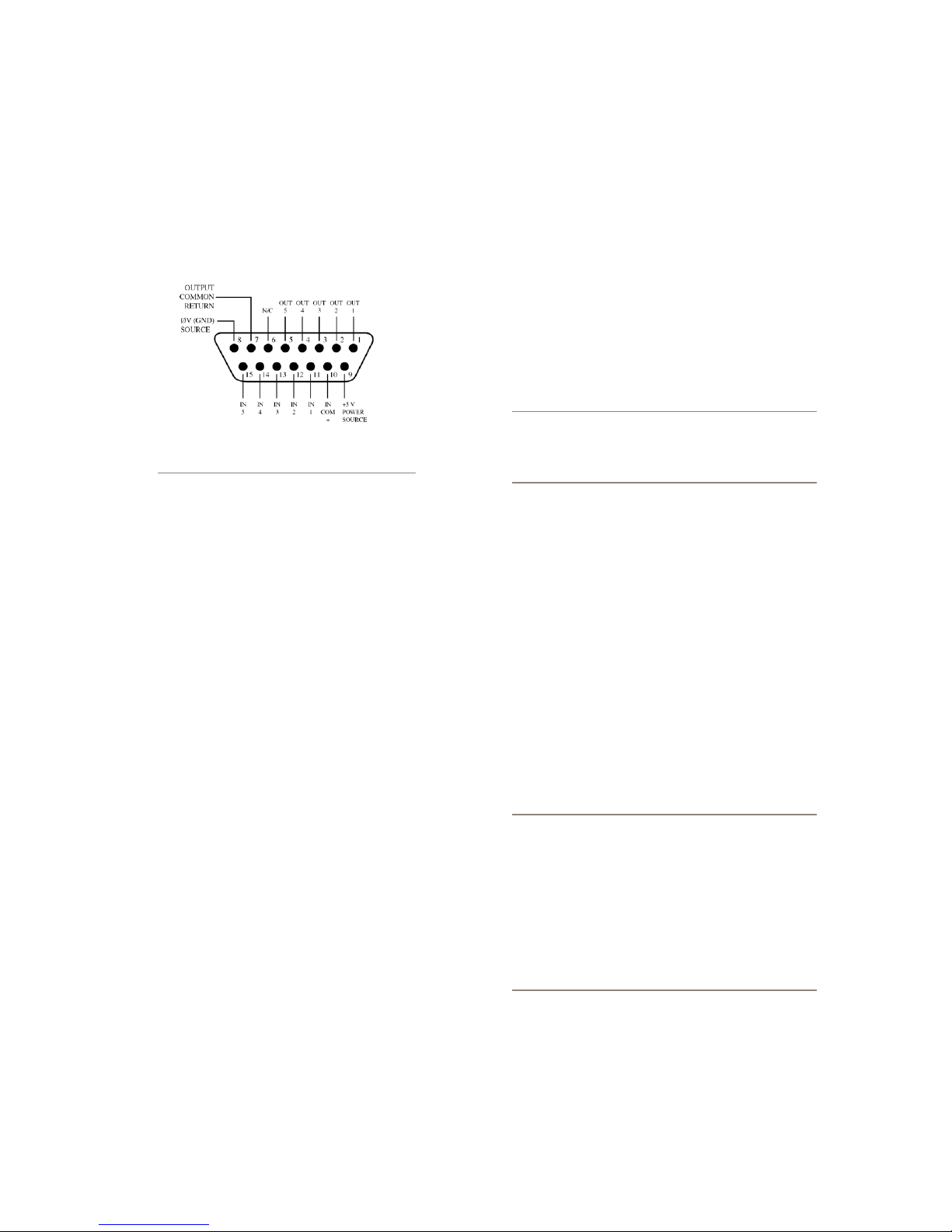
GPIO Connections
The QOR.32 includes eight GPIO ports, with pinouts
in the same conguration as the GPIO ports on other
Axia products. Please refer to Chapter 5: Conguring
GPIO for the functions of these ports and wiring dia-
grams for their DB-15 connectors.
Figure 1-4: GPIO Connector Pin-Outs
tions to other QOR.32 units, or, in larger networks,
for connections to an Ethernet Core switch. Note
that these two ports are used as trunks and are not
intended for connection to Livewire source devices
such as Audio Nodes.
iQ Frame and CANBus Connections
iQ frames need only a single data / power connection
to operate. The QOR.32 includes four power/CANBus
connections for use in conjunction with your iQ control
surface. The accessory CANBus port is an additional
port that is available for future use.
Important: Like any electronic device, iQ can
be affected by static electricity. Use of a personal grounding device is strongly recommended while handling the unit during installation.
In most cases, a GPIO port will be associated with
a single source such as a CD player, studio microphone,
profanity delay, et cetera.
Optional PathnderPC software may also be used to
monitor and control GPIO for advanced applications.
The interconnections to GPIO ports will vary de-
pending on the type external equipment being used and
whether or not voltage is supplied by an external device.
Chapter 5: Conguring GPIO provides these details.
Ethernet Connections
The QOR.32 has three types of Ethernet connections
and it is important to use them as intended since the in-
ternal Ethernet switch is congured in a specic manner.
The types of connectors available are:
• 100 Mbps PoE (Power-over-Ethernet) ports designed
to be used with future Livewire accessories that will
obtain their power directly from their Ethernet con-
nections. These ports may also be safely used with
standard, non-PoE devices.
• 100 Mbps Ethernet standard ports are used to con-
nect PCs or other Livewire devices to your Livewire
network. These devices might include additional
Livewire nodes or PCs running the Axia IP-Audio
driver.
• Two 1000 Mbps (Gigabit) ports are used for connec-
Your iQ surface must be connected to a grounded
metal permanent wiring system or other equipment
grounding conductor using the grounding lug located on
the console chassis. For ground sources, we recommend,
in order of preference:
• “Station Ground,” the heavy copper strap found in the
walls and oors of many radio studios.
• AC Safety Ground — the “3rd prong” of a nearby
outlet.
• A bonded electrical conduit.
#12 AWG GREEN stranded wire is the minimum
wire gauge acceptable for grounding the iQ mixer.
Important: Grounding reduces the risk of electric shock by providing a “path of least resistance” for electric current. Improper grounding
can result in a risk of electric shock.
Check with a qualied electrician if you are in
doubt about how to properly ground this equipment. If your local electrical code prohibits the
use of a Station Ground for this purpose, as de-
scribed above, use the specic “Safety Ground”
your local regulations mandate.
Console 1, 2, 3
There are three 6-pin Molex connector that are used
to provide DC power (48 vdc) plus CANBus data to your
iQ control surfaces.
1: Setup and Connections • 7
© 2014 Axia Audio - Rev 1.3.1
Page 16
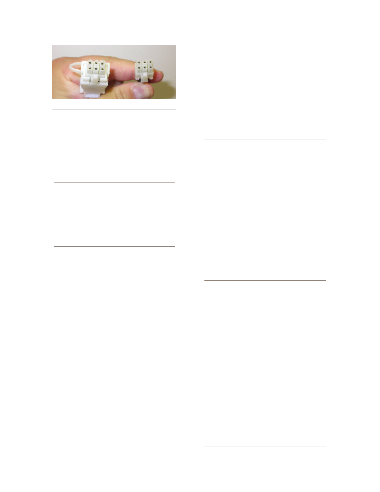
Figure 1-5: Detail of data/communication cable ends.
iQ frames must each be connected to a CONSOLE
port on the QOR.32 using only the supplied 6-conduc-
tor cables. Each frame has a discrete connection to the
QOR.32 A maximum of three fader frames (one Main
plus two others of any type) can be connected to a
QOR.32.
Note: Does it matter what Core port I connect
a console frame to? Fader channel numbers
are dependent on the QOR.32 console por t to
which you connect the fader frames. The Console 1 por t will assign the lowest channel numbers. Console 2 and Console 3 will assign higher
fader channel numbers. This scheme permits
you to arrange your fader frames in any desired
conguration and automatically assign channel
numbers to your faders.
connector used on the Axia Accessory panels. This adap-
tor will simplify wiring of your CANBus accessories.
What is CANBus? Controller Area Network
(CAN) is a multicast shared serial bus standard,
originally developed in the 1980s by Rober t
Bosch GmbH, for connecting electronic control
units (ECUs). Although initially created for automotive purposes, nowadays it is used in many
embedded control applications.
The CAN data link layer protocol is standardized
in ISO 11898-1 (2003).
IP Address Conguration
To access System Settings from the iQ console,
press-and-hold the Meter and Clock key for three sec-
onds. The Studio display now shows the options and the
Studio Monitor control is used to navigate, select options
and change parameter values. Options available are:
• IP Address
• Subnet Mask
• Gateway
• Save and Reboot
1: Setup and Connections • 8
One end of each iQ power/communication cable is
tted with a strain relief. Connect this end to the Molex
connector on the back of the QOR.32. Connect the other
smaller connector to the Molex socket on each iQ Frame.
Each Frame must have a dedicated power/communica-
tion cable.
Since the CANBus connection cables include power
as well as data, there is a length restriction of approxi-
mately 50 feet. If you require longer cables than those
supplied with your iQ Frames, please contact your Axia
representative.
Accessory
The fourth 6-pin Molex connector on the rear panel
of the QOR.32 is labelled ACCESSORY. This is the
CANBus port that can be used to distribute data and 48
VDC to CANBus switch modules and accessory panels.
Several accessory modules can be connected in a daisy-
chain conguration with a termination on the last ac-
cessory panel. An Axia CANBus adaptor is available to
convert the Molex CANBus connector to the RJ-45 type
To exit, select EXIT and press the Studio Monitor
control.
Note: After making changes to any QOR.32 IP
address settings, you must reboot the unit for
these changes to take effect.
“Gateway” settings on a QOR.32 are not usually re-
quired; however, a valid gateway enables access to the
iQ conguration remotely, from outside your network. A
gateway also facilitates the use of an external NTP serv-
er. Enter the IP address of your master router (the one
with external network connections) whenever you’re
given the option to enter a gateway address.
Note: If your system employs an Ethernet core
switch, the Ethernet core switch must have an
IP address that is lower than any of your iQ units
or Ethernet edge switches. This function of the
IGMP standard ensures that the multicast querier is handled by the core switch if one exists.
The querier will be passed off transparently to
another switch should the core switch fail or be
disconnected.
© 2014 Axia Audio - Rev 1.3.1
Page 17
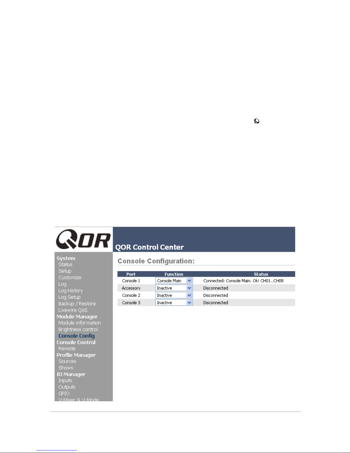
Console Conguration
Now that your iQ has an IP address and you have
a fader frame or two connected, you will need to tell
the QOR.32 what is plugged to its CANBus slots so that
fader numbers can be assigned. You will need to provide
your computer with a static IP address that is in the same
network as the iQ. For example, if you gave the iQ an
IP address of 192.168.2.40, a good IP address for your
computer could be 192.168.2.45.
Once your computer is congured, enter your iQ’s IP
address into your PC’s browser, and when the iQ Con-
trol Center appears, choose Console Cong from the
iQ main menu. When you connect to the iQ, you will be
prompted for a user name and password. By default, the
user name is “user” and there is no password.
In the example shown in Figure 1-6, we have a Main
Frame connected to Console Port 1 and a Phone Frame
connected to Console Port 3. In this conguration, the
faders on the Main Frame will be assigned channels 1
through 8 and the faders on the Phone Frame will be as-
signed channels 9 through 14.
What’s Next?
Take a break! You’re done with initial set-up. When
you’re ready, continue to Chapter 2: iQ Inputs and Out-
puts to walk through the software conguration of the
Inputs and Outputs on your iQ.
Figure 1-6: QOR Control Center
1: Setup and Connections • 9
© 2014 Axia Audio - Rev 1.3.1
Page 18

Cng t pad us,
t m ldng —
t’ e. (N uc.)
1: Setup and Connections • 10
© 2014 Axia Audio - Rev 1.3.1
Page 19
Chapter Two:
these physical connectors. Now, let’s look at the software
conguration of these inputs.
Inputs and Outputs
In this chapter we’ll discuss how to congure the in-
puts and outputs for your iQ system by using your com-
puter’s web browser. While browsing this chapter you
may nd useful the iQ block diagrams in Appendix B.
iQ has a built-in Ethernet switch and Web server for
options conguration. To access it, all you need is a com-
puter connected to its Ethernet switch. Since Livewire IP
addresses are managed without DHCP, you will need to
ensure that your PC has a manually-assigned IP address
in the same subnet as the QOR.32. Contact your network
administrator if you are not sure how to set up a xed IP
address for your PC (but if you’re reading this, we think
you’ve probably got it covered yourself).
Note: Axia web interfaces have been tested with
Microsoft
er, but also work with other browsers.
Adobe
time monitoring features but is not essential for
setup and conguration. If installed, your pop-
up blocker must be disabled. You may download
Adobe Flash Player at http://get.adobe.com/
a s h pl a y e r /.
Once your PC is properly connected to the Axia
Livewire network, direct your web browser to the IP ad-
dress of your iQ. When you connect to the iQ, you will
be prompted for a user name and password. By default,
the user name is “user” and there is no password.
First, we’ll walk through the Audio IO Manager to
congure your Inputs and Outputs. Then, we will illus-
trate how Source Proles and Show Proles are used
with your iQ system.
(TM)
Internet Explorer, version 6 or lat-
(TM)
Flash Player is used for some real-
Inputs
Your QOR.32 has several connectors on the rear
panel that accommodate microphones, analog stereo
line and AES inputs. Chapter 1 discussed the details of
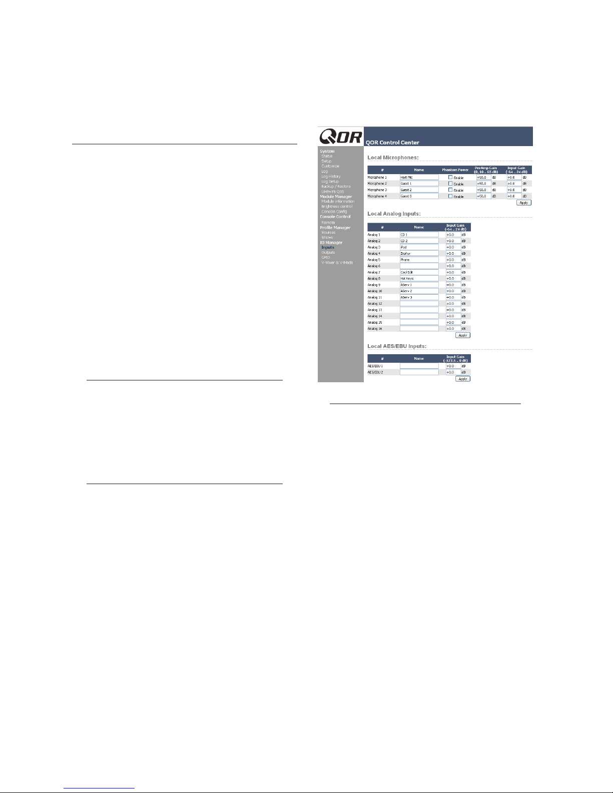
Figure 2-1: Audio IO Manager - Inputs
Figure 2-1 shows the web page conguration for In-
puts for your QOR.32. There are three types of inputs.
Microphone Inputs
The four XLR-type connectors on the rear panel are
intended to be used for mono microphone signals. Each
of those inputs has the following parameters:
• Phantom Power (48 vdc) is individually enabled
for each of the four microphone inputs by selecting
this check box.
• PreAmp Gain is adjustable to a maximum of 65 dB.
This setting will adjust the microphone level prior to
all other signal processing.
• Input Gain is adjustable from -64 to +24 dB. If you
are conservative with your PreAmp gain, you may
wish to apply a few dB of additional gain at this stage.
Analog Line Inputs
These sixteen inputs are for line-level stereo signals
connected to the analog line RJ-45 connectors on the
rear panel. They have only one adjustment.
v
2: Inputs and Outputs • 11
© 2014 Axia Audio - Rev 1.3.1
Page 20

• Input gain allows you to specify a gain from -64 to
+24 dB.
AES/EBU Inputs
There are two AES/EBU digital inputs on RJ-45 con-
nectors. These digital inputs are equipped with sample
rate converters so a specic incoming sample rate or
AES clock is not required.
• Input gain allows you to specify a gain from -127.5
to 0 dB.
Be sure to click Apply after making changes in each
input section.
Now that the inputs have been tweaked for proper
system audio levels, we can manage that audio and auto-
matically associate logic with the different sources you
have connected to your iQ. We use a concept that we call
Proles to do this.
What’s a Profile?
A Prole is a group of parameters that are stored in
memory for instant recall. The use of Proles makes
the operation of your iQ quick and intuitive. In the iQ
console’s design, there are two types of proles: Source
Proles and Show Proles. Show Proles (discussed in
detail in Chapter 3) contain all of the “snapshot” settings
that would be associated with a console scene or preset.
This terminology is commonly used in the sound rein-
forcement or recording studio industries.
Show Proles
Our Show Proles keep track of monitor bus set-
tings, fader channel assignments, jock preferences, lock-
outs and many other parameters.
Source Proles
One of the most repetitive and tedious parts of studio
building has always been tying “data” to audio sources.
Consider the wiring of analog line selector modules: you
needed a cable for the remote audio source, a set of wires
for a “start” closure, another set for “stop” — even with
TDM routers, an operation as seemingly simple as logic-
follows-audio often turns out to be not so simple.
Mix-minus and IFB generation has also been a prob-
lem in the past. Too often it’s a complicated process that
requires air talent to correctly determine source and bus
assignments at a moment’s notice. How many times has
unwanted audio been aired thanks to this error-prone
procedure?
Your iQ eliminates these headaches by automatical-
ly merging audio, logic and program data into a single,
routable information stream. Since audio in a Livewire
network is transported as packetized data, it’s easy for
us to “piggyback” other data along with the audio. This
association is accomplished through the use of Source
Proles.
A Source Prole contains all of the parameters that
are unique to a specic audio input (source) as it applies
to a specic iQ console. Source Proles can assign mod-
iers to an audio input. Characteristics like Pan, Trim
and even Mix-Minus source selections can be set in the
Source Prole and automatically loaded whenever that
source is assigned to an iQ fader.
The result of all this is that iQ is always presented
with complete, consistent information about how you
want a given audio input (source) to be handled. Your
board operator will never have to worry about Mix-Mi-
nus again!
Source Proles allow you to control access and con-
gurations of the individual sources as they are used on
each iQ console in your facility. Source Prole param-
eters may include name, source type, backfeed prefer-
ences, associated logic and much more.
2: Inputs and Outputs • 12
Source Conguration
The iQ web browser interface is used to congure
Sources. To get started:
• Open the web browser on your computer and point it
to the IP address you previously assigned to your iQ.
• You’ll be prompted to enter a user name and pass-
word. The default user name is “user”. Leave the
© 2014 Axia Audio - Rev 1.3.1
Page 21
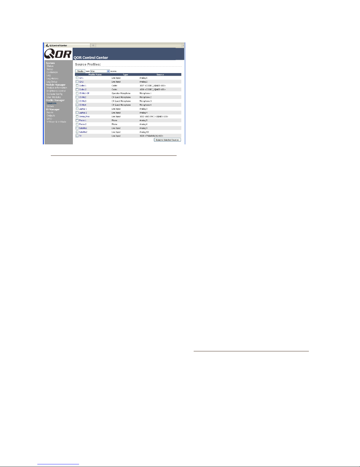
Figure 2-2: Source Prole s
password eld blank.
• Select Sources to proceed to the source setup page.
You will now see the Sources section as shown in
Figure 2-2. In this example, many of the sources have
already been congured.
Note that iQ has three different classes of audio
sources. Most originate with the rear panel input connec-
tors and are used locally in the iQ; some audio sources
may be obtained from other devices in your Livewire
network, and some audio sources (PGM1, PGM2, etc)
are generated internally.
With that in mind, let’s discuss conguring your local
sources and making them available for fader assignment.
Creating a New Source
Your rst choice denes what type of source you’re
setting up, which is important since GPIO, mix-minus
and other console behaviors are decided based on your
choice. Your choices:
• Operator is the board operator’s mic. It is the source
mic for iQ TALK TO functions. Its logic mutes the
CR monitors and Preview when ON.
• Producer is used for in-studio Producer’s mic posi-
tions. It has associated GPIO logic which can operate
TALK TO functions from a remote producer’s panel.
It also mutes CR monitors and Preview when ON.
• CR Guest is used for any other guest mic in the con-
trol room. Its associated logic automatically mutes
the CR monitors and Preview when ON.
• Studio Guest is used for any mic located in a sepa-
rate studio. Its logic mutes the Studio monitors when
ON.
•
External Mic is used for any mic located outside of
a CR or studio. It functions like a Guest microphone
but does not include any muting logic.
•
Line is used for any line input audio source, analog
or digital. A GPIO logic port can be used to provide
machine start/stop pulses if desired.
•
Phone denes this source as a hybrid or broadcast
phone system input. A summed mono mix-minus is
automatically provided.
• Codec marks this source as a codec. A dual mono
mix-minus is provided; one PA feed (right) + one tal-
ent feed with talkback (left).
•
Computer Player denes this source as originating
from a PC. Associated GPIO logic can be used to
send start/stop signals to a playout system.
• Studio Feed denes a source that receives a back-
feed, and generates an IFB backfeed in return. This
is intended for an external studio source which you
wish to generate a talkback channel for.
Once you have selected the source type, click the
Create button to proceed to the Source Prole options.
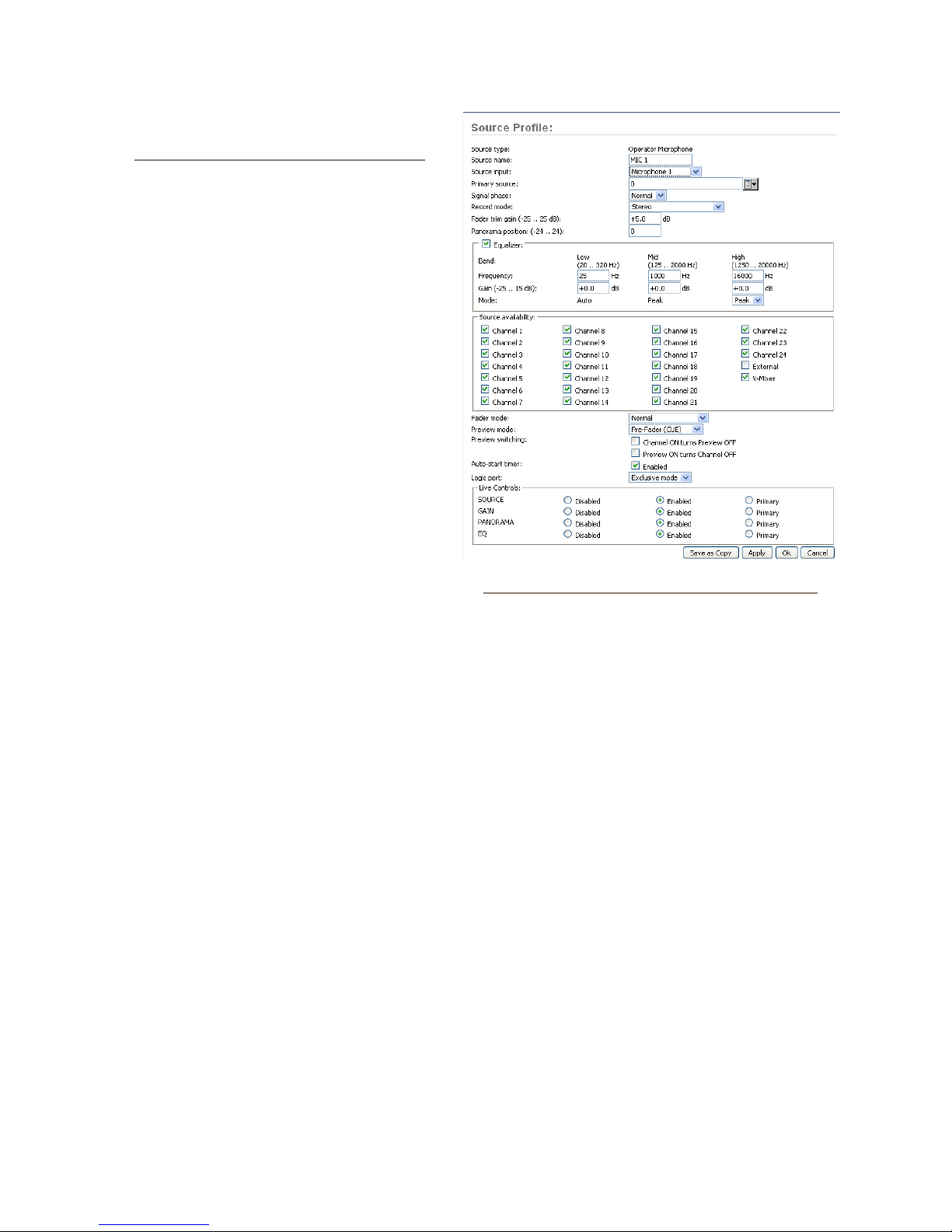
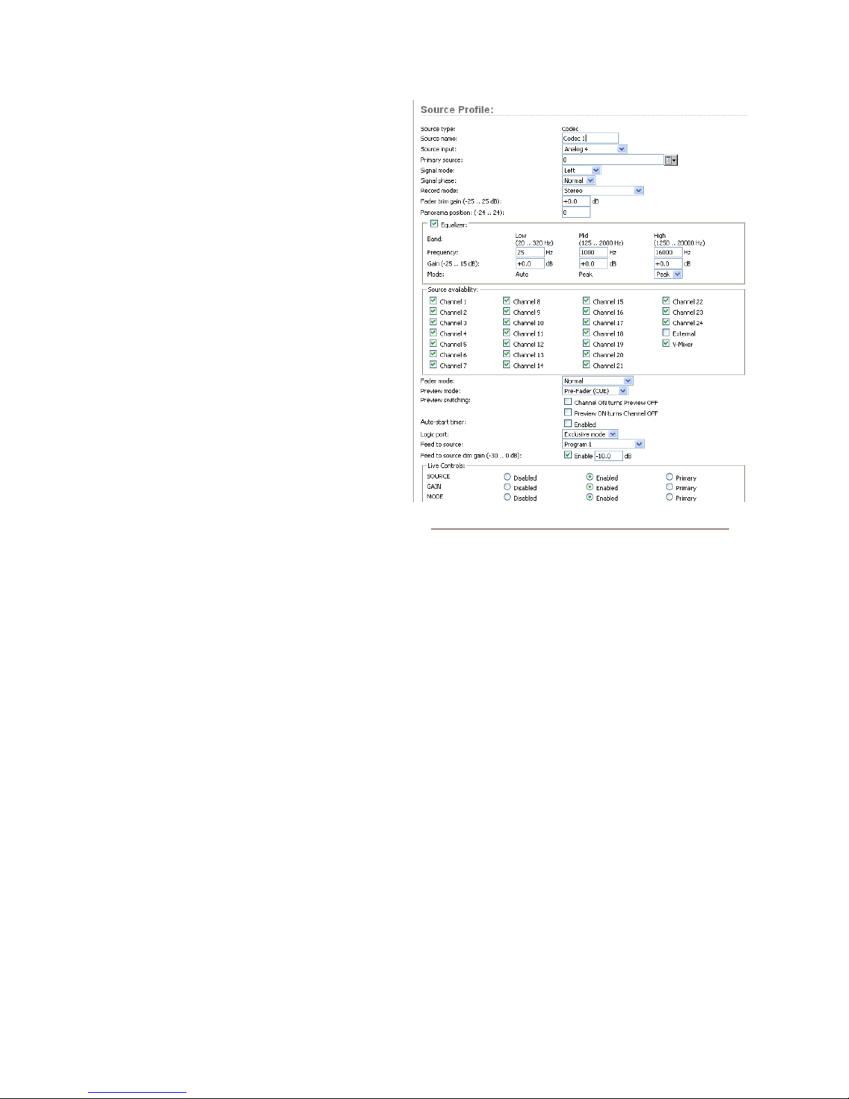
Figure 2-3 shows the setup options screen for a
typical Microphone source. Figure 2-4 shows a Codec
source which has a few different settings, and Figure 2-5
shows a Line source. The following sections describe
these Source congurations in detail.
Source Type
This is a display-only parameter and shows the
source type you selected in the previous step.
About Mics and Headphone Feeds: iQ provides you with several headphone options, all
selectable from iQ monitor control section. The
headphone output provides a feed intended
for the Host (board-op’s) mic position and includes the ability to monitor the Preview bus
in headphones.
There are two headphone feeds from the studio
monitor section, one for talent, one for guests.
The Studio headphone output sends audio to all
studio talent positions. Talent positions include
2: Inputs and Outputs • 13
© 2014 Axia Audio - Rev 1.3.1
Page 22
a talkback channel that the board-op can use to
communicate using the Talk To Studio function.
The Guest Headphone does not include talkback.
Source Name
Each Source needs a name for display on the con-
sole’s OLED channel displays. Names can be up to 10
characters long and may include spaces or underscore
characters.
Source Input
This setting associates the source with an au-
dio input. It may be a local input in which case you
would choose a local Mic, Analog or AES from the
drop-down menu. This source may also be a Livewire
source which means that it is a network source origi-
nating from some other Livewire device. When you
choose Livewire as your Source Input, you will spec-
ify a network source. See Chapter 7: Livewire Net-
working and iQ for details.
Primary Source
This pop-up window is used to select the network
Livewire source ONLY when Livewire has been se-
lected as your Source Input. See Chapter 7: Livewire
Networking and iQ for more on this.
Signal Mode (Non-Microphone Sources)
Determines whether source will be treated as a mono or
stereo source.
• Stereo feeds incoming L/R signal to left and right
channels of assigned bus(es).
• Left feeds incoming left channel to both channels of
assigned bus(es).
• Right feeds incoming right channel to both channels
of assigned bus(es).
• Sum creates L+R mono mix of incoming stereo
source and feeds it to both channels of assigned
bus(es).
Signal Phase (Non-Microphone Sources)
Determines whether source will maintain normal or
inverted phase relation.
Figure 2-3: Operator Microphone Source
PGM 4 that is post-fader but pre ON/OFF. The mix of
the Record bus is controlled by the Record Mode set-
tings of each source. The options are:
• Stereo: delivers this source in stereo to the Record
bus (default).
• Sum to Left: sums L+R of this source and delivers
the sum to the Left channel of the Record bus.
• Sum to Righ t: sums L+R of this source and delivers
the sum to the Right channel of the Record bus.
The last two options give you the ability to create a
split Record bus which is commonly used for phone re-
corders. The Operator’s mic can be recorded on one side
of a stereo channel while all other sources are recorded
on the other side.
Fader Trim Gain
This setting allows you to specify an amount of gain
from -25 to +25 dB. Fader Trim Gain is applied in the
signal path just before the fader.
Record Mode
2: Inputs and Outputs • 14
The Record Bus of your iQ is a special variation of
Equalizer
Allows you to enable EQ function for the source as
© 2014 Axia Audio - Rev 1.3.1
Page 23
well as predene the three-band EQ settings for the
source.
Panorama Position
Lets you preset pan settings for this input. Pan is
variable in 49 steps, center being 0, far left -24 and far
right +24. This setting can be adjusted on the y by
the operator if permitted by show prole settings.
Source Availability
These check boxes determine which faders (or
other inputs) you’ll allow this source to be assigned
to. For example, if your source is a Control Room mic,
and you only want it to appear on the left-most fader,
you would check only the box marked Channel 1. You
might want to make a CD player available on any fad-
er, so you’d check the boxes for all faders.
You might wish to prevent some sources – espe-
cially off-air signals – from ever being assigned to a
fader, so you would un-check the boxes for all faders.
Figure 2-4: Codec Source
The two nal check boxes,
External and V-Mixer,
determine whether the board-op will be able to assign
the source directly to the CR and Studio monitor and
headphone buses, or to iQ’s Virtual Mixer.
To prevent a source from appearing on these inputs’
selection lists, un-check the relevant box. Generally
speaking, you’d want to restrict sources such as comput-
ers and CD players to fader assignments while sources
such as off-air receivers would be marked to appear only
on the External monitor selection list.
Fader Mode
Denes fader start actions and start logic:
• Normal conforms to the US method of requiring tal-
ent to manually turn the channel on and off.
• Fader Start follows the common European stan-
dard of activating the channel and associated ma-
chine logic when the fader is raised from - ∞.
• Fader Start with Arm works just like the Normal
setting when the fader is not set to minimum position.
When the fader is set to the minimum position, it can
be in an Armed state. This armed state is entered by
pressing the ON Button when the fader is down. The
armed state means that the channel will go to the ON
state when the fader is moved up. When in Arm state,
the channel OFF lamp will be illuminated. The chan-
nel ON lamp will ash in “wink” mode - a long on-
time and short off-time. For all fader modes, pressing
the OFF button at any time will place the channel in
the OFF state
Preview Mode
Permits you to choose whether Preview acts in CUE
(pre-fader) or SOLO (post-fader) mode.
Preview Switching
There are two check boxes in this area. None, either
or both may be checked. The options are:
• Channel ON turns Preview OFF
• Preview ON turns Channel OFF
Auto-Start Timer
When this box is checked, the count-up timer will
start when the channel is turned ON.
2: Inputs and Outputs • 15
© 2014 Axia Audio - Rev 1.3.1
Page 24
2: Inputs and Outputs • 16
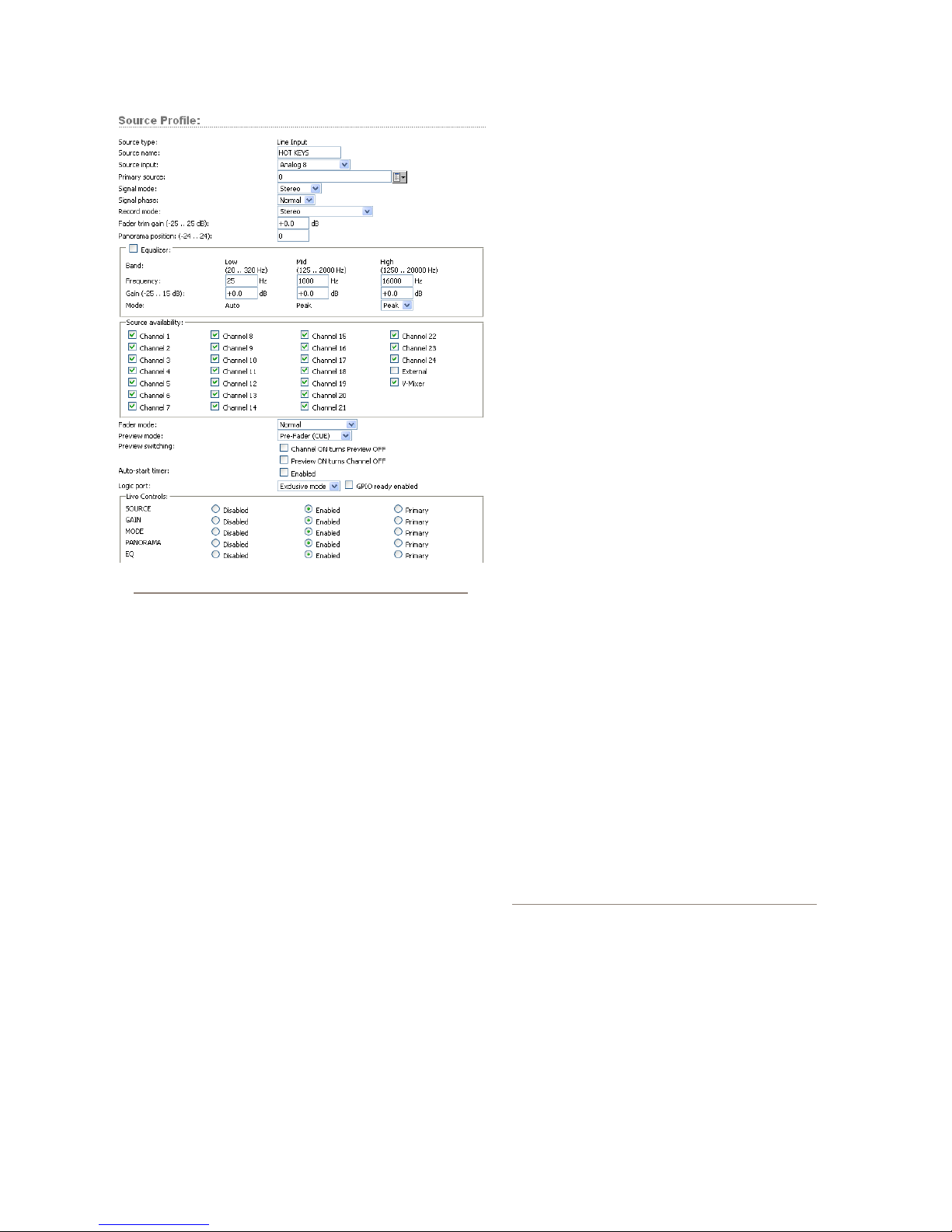
Figure 2-5: Line Source
Logic Port
Allows you disable GPIO machine logic to this au-
dio source device or enable it in two modes. Exclusive
mode permits GPIO control associated with only a sin-
gle fader. Shared mode allows more than one user to
send ON/OFF/START signals to the source via GPIO.
A check box can optionally enable GPIO Ready
mode. This allows devices such as CD players or tape
machines to signal their READY state to the operator
through the OFF button LED. If a device is cueing, its
OFF lamp will not be lit. Linking the device’s OFF lamp
to the Ready command means that a machine must be
cued and ready before the OFF lamp illuminates. If en-
abled, the OFF lamp illuminates when the fader is OFF
and the Ready command is active on the GPIO. If dis-
abled, the OFF lamp illuminates normally whenever the
fader is turned OFF.
Feed to Source (Codec, Phone, Studio Feed only)
If this source is a Phone or Codec type and there is a
backfeed associated with it, this option determines what
audio content is sent back to the source from the console.
• Disabled - No backfeed.
• Auto (Pgm-1/Phone) feeds the Program 1 bus
(minus the source) when this source’s fader is ON,
and feeds the Phone bus (minus the source) when the
fader is OFF. Remember, the Phone bus is actually a
special variant of Program 4. The Phone bus is pre-
fader and pre-on/off to allow speaker-phone style op-
eration thru the Operator’s mic.
•
Program 1 always feeds the Program 1 bus, minus
the source, regardless of the on/off state of the chan-
nel.
•
Program 2 feeds the Program 2 bus, minus the
source.
Program 3 feeds the Program 3 bus, minus the
•
source.
• Program 4 feeds the Program 4 bus, minus the
source.
• Phone feeds the Phone bus, minus the source. Phone
is a pre-fader and pre-on/off variation of Program 4
• Talk Only is a “silent backfeed” that operates when
the Ta lk To function is engaged, creating an IFB to
the source.
Feed to Source Dim Gain (Codec, Phone, and Studio
Feed only)
Normally, Talkback is sent over dimmed backfeed
audio. If you want a hard interruption (Talkback inter-
rupts Program audio), un-check the Enable check box,
which mutes the audio. But maybe your jocks would like
to have just their program audio dimmed, with Talkback
heard over it so they can still monitor air while they’re
being talked to. In this case, input a value by which the
program audio will be dimmed. Adjustment range is 0dB
to -30dB.
About the PHONE, RECORD and PROGRAM 4
buses: The iQ PGM-4 mix bus is a special multi-
purpose bus that does several things at once to
make life easier for the operator.
Sources assigned to PGM-4 are also sent to the
RECORD bus, a special post-fader, pre-on/off
output that can be used to feed recording devices.
At the same time, sources assigned to PGM-4
are mixed and sent to the PHONE bus. PHONE is
an internal bus which does not feed a separate
output; instead, it picks up PGM-4 audio pre-
© 2014 Axia Audio - Rev 1.3.1
Page 25
fader and pre-On/Off and backfeeds this bus
to callers (minus themselves, of course) when
the channel is OFF and AUTO is selected as the
Feed To Source Mode.
Live Controls
This group of radio buttons congures permits “live”
functions for the Options control on each of the con-
sole’s fader strips. Available options will vary depend-
ing on the source type. One setting may be dened as
the Primary or “live” control, which means that the
Options control will vary that setting as soon as you ad-
just the knob. For example, if PANORAMA has been
dened as the Primary function, simply rotating the Op-
tions control will pan the source.
The other functions may be enabled or disabled as
desired. Those that are Enabled may be chosen by the
operator “on-the-y” by depressing the Options control.
When the control is pressed, the OLED display will list
the options that you’ve checked as Enabled in this sec-
tion of the conguration. Pressing the Options control
selects the highlighted option and turning the Options
control will adjust the parameter for that option. De-
pending on the enabled options, the operator will be able
to adjust Source, Gain, Mode, Pan and Backfeed.
Remember to save your work! You may also
“Save as Copy” if you intend to set up another, sim
-
ilar source — you can save a few clicks this way.
Congratulations — you’ve created a Source Proles
You can now bring up your new source on an iQ fader.
iQ Outputs
Output Types
Now that we have congured sources, let’s look at
the outputs of the iQ. Since iQ is a network device as
well as a mixing console, you might expect that it has
two kinds of outputs, Local and Livewire (network).
• Local Outputs - These outputs correspond to the
audio connectors on the rear panel of the QOR.32.
These are used to connect Control Room monitors,
Preview speakers, headphone ampliers, record de-
vices and, of course, your air chain equipment and
processing.
• Livewire Outputs - This is a group of four speci-
ed audio streams that can be delivered from your
iQ to other devices in your Livewire network. See
Chapter 7: Livewire Networking and iQ for more
details on how this works.
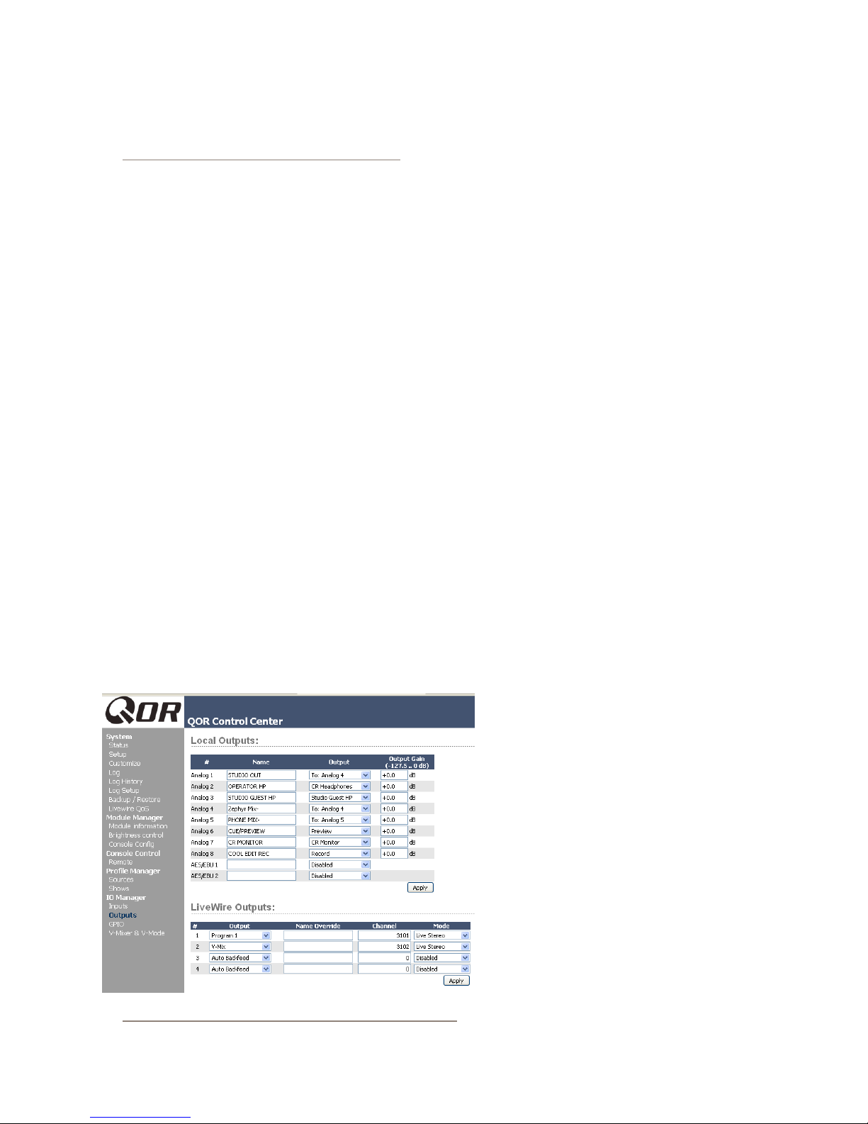
Local Outputs
Your QOR.32 has eight stereo analog line out-
puts and two AES outputs. These may be cong-
ured to deliver:
» Local sources (4 microphones, 16 analog, 2
AES/EBU)
» Backfeeds to any of the above sources that are
congured as Phone or Codec.
»Any of the Program or Monitor feeds that are
created by the QOR.32 (CR Monitor, Studio
Monitor CR Headphones, VMIX, VMODE, etc)
• Output - Using the drop-down menu, select
the desired source that you want to deliver to
your iQ local output.
• Output Gain - The output signal level may be
attenuated to provide an optimal level for out-
board devices. The gain range is from -127.5
(off) to 0.0 dB (unity gain).
Figure 2-6: Assigning an Output from the list box
2: Inputs and Outputs • 17
© 2014 Axia Audio - Rev 1.3.1
Page 26
2: Inputs and Outputs • 18
CAUTION - Once you have made a selection
and applied it, audio is immediately delivered
to the QOR output. Be sure to turn down all
amplier level controls to avoid damaging your
precious equipment — especially your ears.
V-Mixer and V-Mode
The iQ V-Mixer is an “auxiliary” virtual mix-
er that can be used to mix ve stereo sources and,
from this mix, create another new source that may
be used like any regular source.
V-Mode is a signal converter that allows you to
manipulate some mono-mode sources. V-Mode has
one input and one output, thus creating one additional
source.
V-Mixer and V-Mode outputs are assigned in the iQ
Outputs section and delivered to your studio or your
Livewire network. Once V-Mixer and V-Mode signals
are a part of the network, they can be loaded on any lo-
cal or networked console fader, or routed to any other
network destination.
V-Mixer Controls
The V-Mixer works independently of the iQ console.
Static control of V-Mixer is available through the iQ web
pages.
Even though the “V” in V-Mixer stands for “virtual”,
you can in fact perform a certain amount of “hands-on”
mixing. Although you don’t have physical control of the
virtual faders or virtual ON/OFF switches, adjustments
made to the V-Mixer take effect as soon as you apply
them. While you may not want to operate an entire show
this way, it’s valuable to know that V-Mixer changes
made “on the y” will take effect immediately.
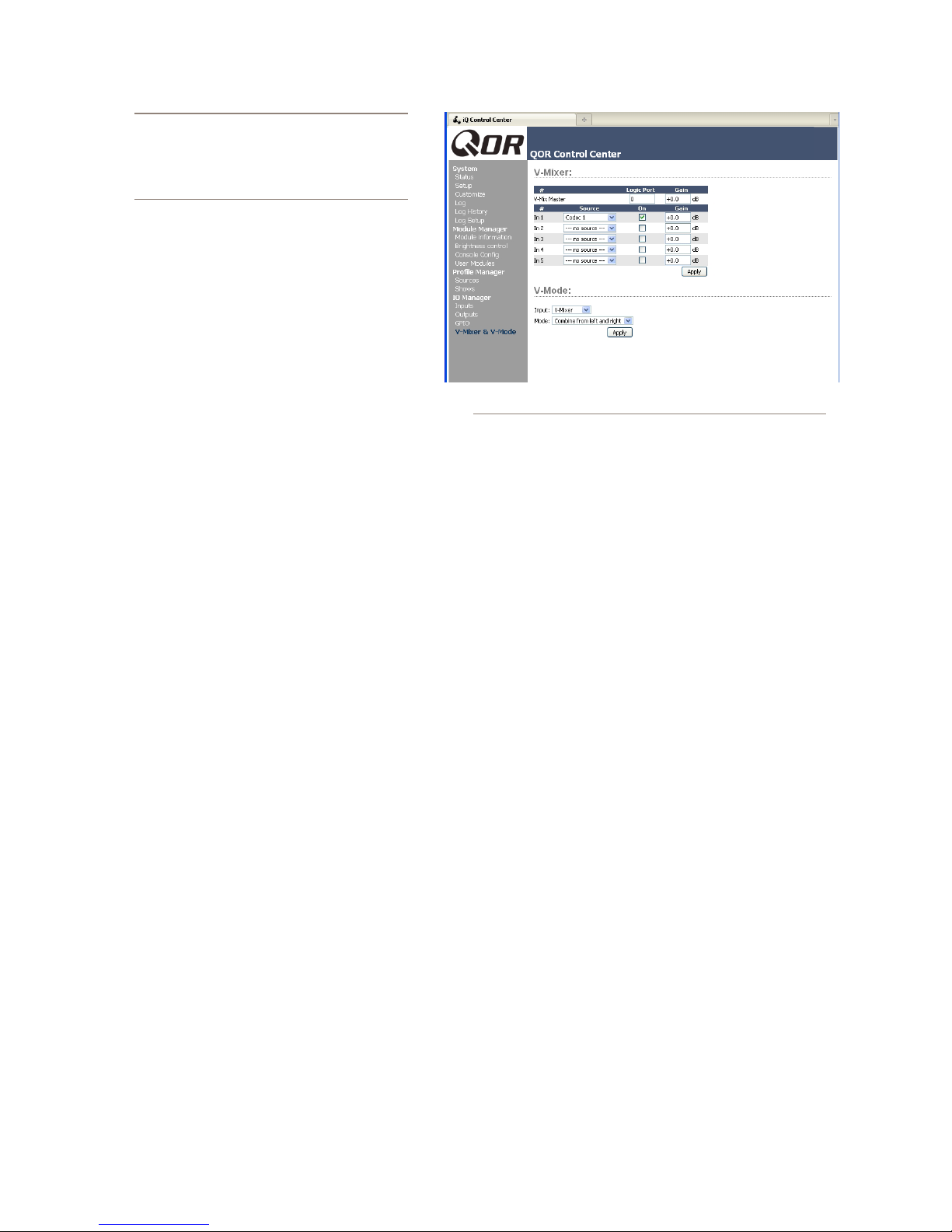
Figure 2-7 shows the V-Mixer and V-Mode setup
found in the iQ web pages. At the top of that page, you
can see the V-Mixer sub-mixer with its ve stereo inputs.
Below that you will see the V-Mode section. Let’s look
at the controls and see what they do.
Figure 2-7: V-Mixer and V-Mode
At the top is the V-Mix Master eld. This gives the
option to assign a Livewire GPIO channel for control of
the VMixer. This channel number also gets assigned to
a GPIO port, allowing you to have ON/OFF control of
VMix channels through GPIO. The last option applies a
gain stage to the nal mix the ve inputs.
Controls for the V-mixer’s input channels include:
• Source: From the drop-down menu, you may select
any source previously dened with a Source Prole.
• On: Simply determines the ON/OFF status of the in-
dividual V-Mixer channel.
• Gain: This setting allows you to specify a gain set-
ting for the channel that will control its mix level.
The range is from -80 dB (effectively off) to +10dB.
Note that you may also specify a gain setting for the
V-Mix Master, which is the output of the V-Mixer.
At the bottom of the V-Mix section is an Apply but-
ton. Any changes you make will be saved when this but-
ton is pressed. Be sure to save your changes.
What does V-Mode do?
All of the program busses of the iQ are stereo. Some-
times, though, special circumstances require only one
channel of an audio source, or a mono sum. V-Mode lets
you accomplish this easily.
V-Mode Controls
V-Mode allows you to perform special manipulations
on a stream. The controls are as follows:
© 2014 Axia Audio - Rev 1.3.1
Page 27
• Input Selector contains a drop down menu that al-
lows you to select from a range of sources for each
V-Mode input. You may choose from local Core
sources including PGM-1/2/3/4, and VMIX.
• Audio Mode is the magic box that transforms your
stereo stream into something else. You may choose
from any of the following options:
» Pass Stereo: Passes the Left and Right chan-
nels as is, without modication.
» Mono sum to L: Creates mono sum and directs
it to the Left channel only.
» Mono sum to R: Creates mono sum and directs
it to the Right channel only.
» Combine from left and right: Creates a dual
mono stream by summing the Left and Right
channels.
The output of V-Mix and V-Mode channels can be
assigned to outputs like any normal audio source.
down selector. Click on the drop-down for output #3
and choose to Analog 5 as shown in Figure 2-6. By
simply choosing to Analog 5, iQ knows to deliver a
backfeed that is a mix-minus of Analog Input 5. (The
output chosen to deliver this backfeed is arbitrary -
we chose Output 5 just for this example.)
4. Click Apply.
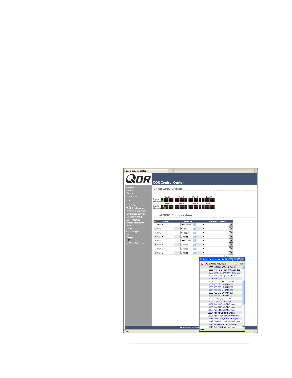
5. Now point your browser to the iQ GPIO Con-
guration screen (Figure 2-8). You may also use a
GPIO Node in lieu of iQ’s built-in GPIO ports; just
point your browser to that Node’s IP address instead.
6. The GPIO setup screen uses the same method
of assigning devices to ports as other Livewire de-
vices. Pick a port to map your Phone channel’s con-
tact closures to, using the list tool, and click Apply.
Figure 2-8 shows the GPIO section of an IQ. (Axia
Element console
also have eight GPIO ports.)
s and GPIO nodes are similar, and
Adding Backfeeds and GPIO
Since making a mix-minus and mapping
contact closures is often done at the same
time a new Source Prole is constructed,
let’s briey recap those procedures.
Let’s say you’ve connected a hybrid to
Analog Input 5 of your iQ. You’ve construct-
ed a Source Prole for it, and you now want
to give it a mix-minus backfeed and set up
a GPIO contact closure for the “take” and
“drop” functions. Here’s how:
1. Make sure that, in your hybrid’s
Source Prole, the Source Type op-
tion is set to “Phone” and the Feed to
Source is set to “Auto (Program 1 /
Phone)”.
2. Use your Web browser to connect
to the iQ Outputs screen (Figure 2-6)
and set up the mix-minus for Output #5.
3. Just to the right of each Local
Output name box , you’ll see a drop-
Figure 2-8: GPIO Conguration
2: Inputs and Outputs • 19
© 2014 Axia Audio - Rev 1.3.1
Page 28

The process is complete: you’ve made a Source Pro-
le for your phone hybrid, created a mix-minus, mapped
it to an audio output, and associated a GPIO port for con
tact closures associated with the source.
-
To conrm, choose the
iQ’s fader strips and load your new Phone source. Now
press the
status change appear in the display above the channel
to indicate that the operator’s mic is talking to this tele
phone hybrid through it’s backfeed channel.
the green indicators that have appeared on the port rep
resenting your hybrid; switch the iQ channel On and Off
and you’ll observe the tally change with the active pins.
Tal k key just below the fader; you’ll see the
Now look at the GPIO screen on your browser. Note
Options key on any of your
What's Next
When you’re ready, join us in Chapter 3: Console
Operation where we’ll show you how to use the various
controls on the iQ mixing surface.
-
-
2: Inputs and Outputs • 20
© 2014 Axia Audio - Rev 1.3.1
Page 29

Chapter Three:
Console Operation
With iQ, our goal is to provide you with the most ef-
cient human-machine interface possible for fast-paced,
complex programs where board operators must multi-
task without error. As such, iQ brings a whole new level
of control and sophistication to the broadcast studio,
while providing very familiar, intuitive operation.
Overview
iQ was designed to perform equally well in air or
production studios. The clean interface enhances speed
and accuracy without clutter or confusing controls.
In addition to the iQ Main frame, there is an 8-fader
expansion frame, a 6-fader frame with controls for use
with select Telos phone systems, and a 6-fader frame
with ten programmable “User” keys (two groups of ve
keys).
In this chapter we’ll rst give you a high-level over-
view of iQ capabilities. Then, we’ll give you detailed ex-
planations of the various controls and functions.
Show Proles
iQ can be completely re-congured, instantly, to suit
different types of shows. By recalling any of four previ-
ously stored Show Proles, talent can change board set-
tings from a phone and microphone intensive morning
show to a personality-based music show – or any other
kind – at the touch of a button.
Show Proles are easily toggled by pressing the Pro-
le key located at the top of Monitor section. Construc-
tion and administration of Show Proles is covered in
Chapter 4: Show Proles.
Sources, Channels and Faders
During the course of this chapter, we’ll refer of-
ten to sources and channels. These are not the same!
“Sources” are microphones, CD players, outputs from the
playout system, telephone hybrids, etc.
“Channel” would normally be used when referring to
iQ’s linear faders and associated on/off controls, OLED
displays, bus assignment keys, etc.
Sources are assigned to faders for use on-air or in
production. During initial conguration, the Source
Proles are programmed by the engineer for appropri-
ate logic and options (as outlined in previous chapters);
afterwards, whenever that source is assigned to a fader,
source logic follows.
Displays
Like a traditional console, iQ includes built-in meter
displays. The iQ’s OLED meters can be congured to
VU or PPM metering standards.
The iQ Main Frame has dedicated meter displays for
Program buses 1, 2 and 3, plus a multi-function meter.
This meter, used in switched mode, toggles between a
preset selection of metering options. The meter tally
tells you what bus the meter is metering.
In addition to the meter displays, iQ, has a time of
day clock and a count-up timer.
Fader settings are instantly recongured whenever a
source is selected, to accommodate the unique require-
ments of the source. For example, a fader controlling a
microphone source also controls appropriate monitor
mutes. A fader controlling a line source may send “start”
and “stop” commands when the channel is turned on and
off.
Sources such as an off-air feed can also be assigned
directly to the monitors for auditioning without being as-
signed to a fader.
Mix-Minus
Mix-minus setup, especially for live broadcasts, has
always been one of the most confusing aspects of run-
© 2014 Axia Audio - Rev 1.3.1
3: Console Operation • 21
Page 30

ning a radio console. iQ makes mix-minus easy by auto-
mating it. The operator never has to worry about sending
a source back to itself and getti ng feedback— it just can’t
happen!
via the Internet and applied by the station engineer. Axia
Support recommends performing backups or making
printouts of Show Proles and other conguration data
before applying new software updates.
3: Console Operation • 22
Several xed and auto-switching mix-minus choices
are possible, and are congured for each source when
Source Proles are dened by the engineer (see Chap-
ter 2 for details). Once this setup is done, no further
tweaking is needed; the operator simply uses the source.
A fader’s status display tells operators when a particu-
lar source has a mix minus output, and even tells them
which audio mix is being backfed.
iQ will generate as many mix-minus outputs as there
are faders, each with its own automated mix minus feed.
If you have 16 faders, you can have 16 mix-minuses!
GPIO
Chapter 2 explained how sources can have associat-
ed GPIO (General Purpose Input/Output) control associ-
ated with them. External GPIO interfaces are connected
to iQ via the Livewire network (more details in Chapter
7) , so you can locate the actual machine connections ei-
ther physically close to source equipment or in a central
equipment room.
During installation, the engineer congures sources
to accept and provide logic commands by selecting vari-
ous options. For example, studio mics may be set up to
automatically mute the studio monitor speakers and il-
luminate an on-air warning light when turned on. The
same sources can be congured to accept GPIO logic
inputs from buttons, so that each studio guest can have
their own On, Off, Tal k, and Mute keys.
Line sources can be congured to receive start and
stop commands from the iQ as well. Start/stop messages
can also be passed, via Ethernet, to a computer-based
playout system.
Software
The iQ operating system uses a high-performance
embedded Linux kernel to help ensure bulletproof, 24/7
operation. Software updates can be obtained from Axia
iQ Main Frame - Callouts and Operation
This section provides a “bird’s-eye view” of the iQ,
with full descriptions of its controls and their functions.
Although an iQ console may have a xed number of
faders, you are not limited to that number of sources.
Just like iQ’s big brother, Element, you may assign any
source to any fader. Unlike Element, iQ’s metering is
built-in.
The iQ Main Frame is laid out in a conventional
manner with the monitor and ancillary controls located
on the right side of the frame. Let’s look at each of these
sections in detail.
1. Channel OFF Switch: You know what this
does.
2. Channel ON Switch: When the channel is in
fader-nor mal mode the ON key turns the channel on
and the OFF key turns it off. The channel On and
Off functions also provide logic (start and stop puls-
es, monitor muting, etc.) specic to the source type.
For example, if a control-room mic is assigned to a
fader, the CR monitors and Preview speakers will
mute when that fader is turned on and when CR mi-
crophone sources are Previewed. If a fader is hosting
a microphone source, pressing the On key when the
fader is already on mutes the channel, providing a
“cough” function, until the On key is released.
3. SOFT Key: Each channel has a Soft Key. The
OLED display tells you what function the soft key
is currently controlling. The default action depends
upon the type of input assigned to that fader, which
is dened in the Source Prole. Current functions
of the key are Mute, Talkback and phone hold. This
key is also used to exit Channel Options edit mode.
© 2014 Axia Audio - Rev 1.3.1
Page 31
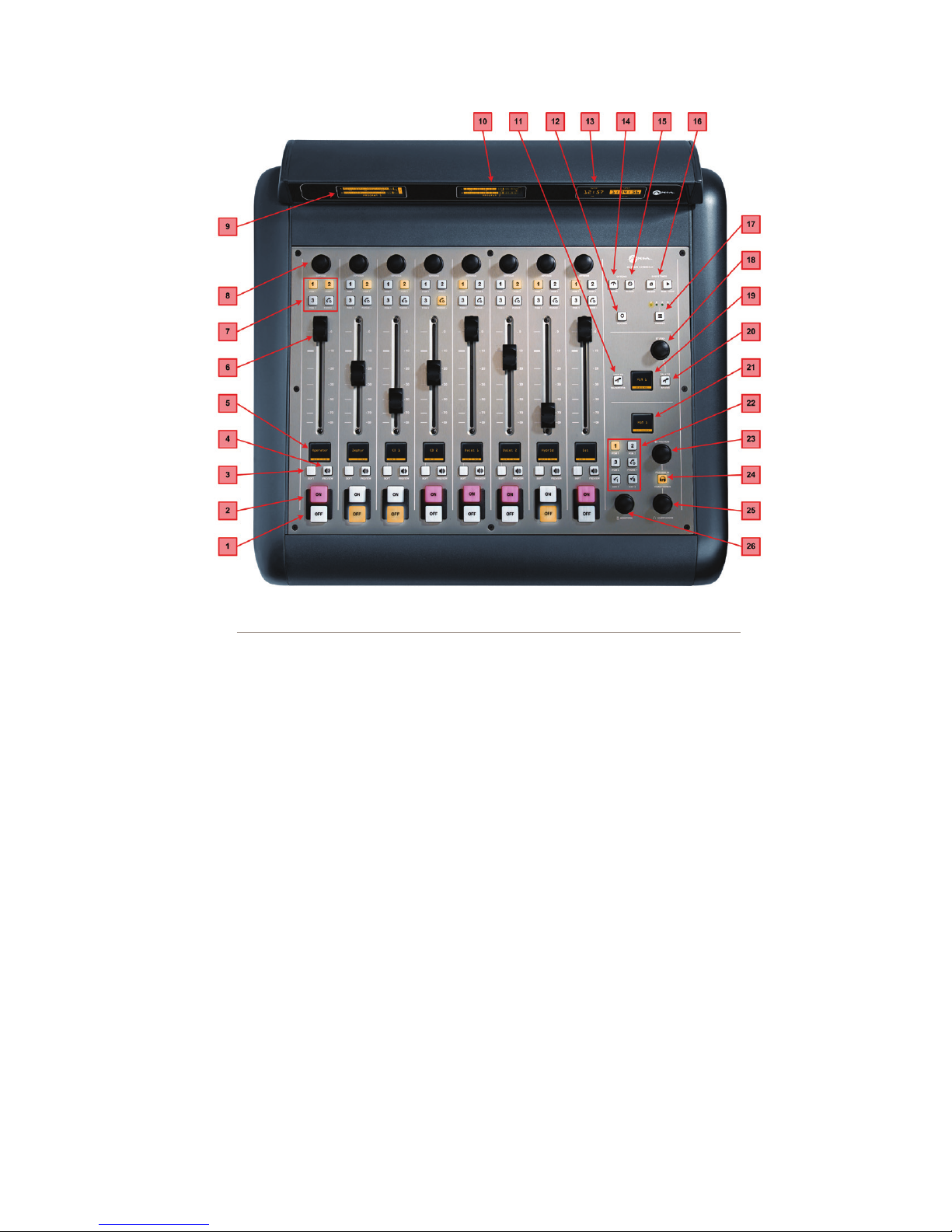
Figure 3-1: iQ Main - Callouts
4. PREVIEW Key: allows the operator to listen
to sources before they air. iQ’s Preview bus allows
auditioning in full stereo. Individual source proles
can change Preview to Solo (post-fader) operation.
The Preview key acts like a latching switch.
Momentarily pressing any channel’s Preview key
assigns that channel to the Preview bus; pressing it
again removes the channel from Preview. To enable
an operator to quickly listen to various sources, the
Preview function can be interlocked: pressing Pre-
view on any channel will remove any other channel
from Preview mode.
If you want to preview multiple channels, pressing
and holding any Preview key temporarily disables
the interlock; other sources can be added to the Pre-
view mix by pressing them. Conversely, channels
can be removed from a multiple Preview selection by
pressing and holding any lit Preview key and dese-
lecting the individual channels you wish to remove
from Preview.
A momentary press of any lit Preview key will re-
move all channels from Preview.
The interlock option for Preview can be disabled in
any Show Prole’s Monitor section so that users can
gang preview sources without the need to press and
hold Preview.
The audio from the Preview bus feeds any speakers
dedicated to Preview, and can also be routed to the
operator’s headphones and CR monitors if desired.
Preview speakers will be muted whenever and CR
microphone is ON, or is assigned to the Preview bus.
5. Channel Information Display: This OLED
display interacts with the Channel Options control
and the Soft key. It is context-sensitive and can dis-
play many different parameters relevant to each fader.
3: Console Operation • 23
© 2014 Axia Audio - Rev 1.3.1
Page 32
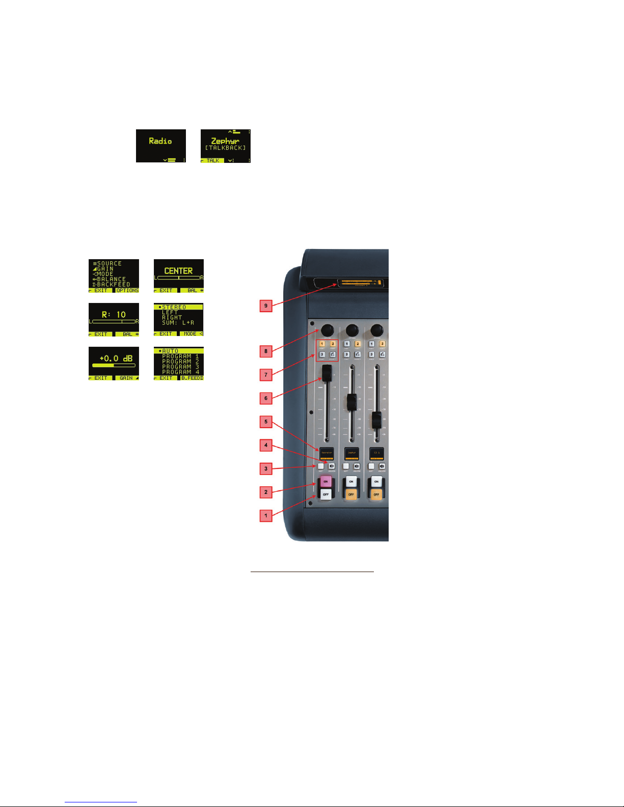
3: Console Operation • 24
Normally the display will show the name of the
source that is applied to the fader (“Zephyr”), and
the function assigned to the SOFT key (“TALK”).
When fader channel parameters are being edited, this
display shows gain and pan settings, mode, backfeed
selection and other parameters that will be depen-
dent on the type of source.
When viewing these menus,
the Options control is
pressed to select the func-
tion, and rotated to set the
value.
Just below the Source name
is a status line. It shows the
status of a channel. It is dis-
played in medium font. In
the previous example, it is
“[TALKBACK].” .
Figure 3-2: iQ Main - Callouts
Here is a list of the different status displays and their
meanings:
» [TALK TO CR] - means that this channel is talk-
ing to Control Room. Used on Guest Microphone
and Codec source types
» [OP T ALKING] - means that this fader is an op-
erator mic and it is currently in use for Talkback
rather than feeding to Program buses
» [MUTED] - means that this channel is muted
» [TALKBACK] - means that this channel is being
talked to, i.e., the talk bus is fed to the backfeed
stream for this fader.
» Src-label - If the source has an associated la-
bel, it will be shown. Source label is normally
used by playout systems to indicate song name
and/or important information. Available only for
Livewire sources.
» Listen Only - The source was loaded in listen-
only mode. No GPIO control is available for this
source’s originating device.
» Used EW - The source is
currently in use elsewhere and
is in listen only mode. As soon
as source is freed, it will be
automatically reloaded in Full
Control mode.
» Src Load Err - An error
occurred during source loading.
Re-load the source.
» No Backfeed - An error oc-
curred during backfeed alloca-
tion for the source. For example,
no resources are available to al-
locate backfeed stream.
» Src Waiting - means that
a new source is waiting to be
loaded. This state is accompa-
nied by a blinking OFF key.
Turn the channel OFF to load
the new source.
6. Fader: The fader controls
the volume of the input source.
There are two modes for the
fader: fader-start and fader-nor-
mal:
• When the channel is used in fader-start mode,
pushing the fader all the way to the bottom of its
travel turns the module off, and sends appropri-
ate logic commands to source equipment. Mov-
ing the fader up turns the channel on and sends
logic commands. In fader-start mode, the On
and Off keys act more as indicators of channel
status; the On key will not turn the channel on
if the fader is at the bottom of its travel. Pressing
© 2014 Axia Audio - Rev 1.3.1
Page 33
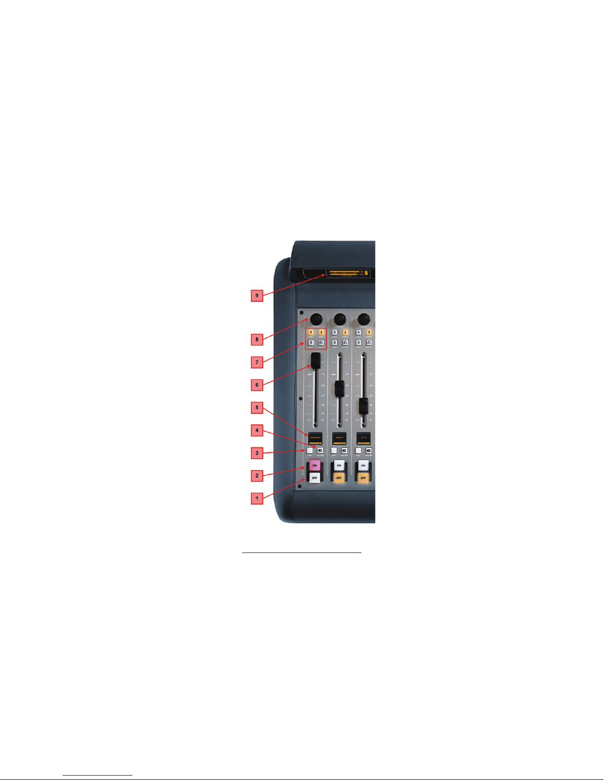
the Off key while moving the fader up suppresses
turning the channel On.
• In fader-normal mode, the on/off status and
start/stop commands follow the channel ON/
OFF switches independently of the fader position.
7. Program Bus Assignment Keys: Each chan-
nel is assigned to any of the three main output buses
by selecting any (or all) of these program bus keys.
Gen e ra l ly, PGM-1 is the main on-air bus and other
buses are used for produc-
tion or other programming
requirements. All program
outputs are post-fader and
post on-off function.
The fourth bus functions
as a regular output bus, but
any sources feeding PGM-
4 are also sent to a special
Record bus that can feed a
dedicated recording device,
as well as to the Phone bus
that sends mix-minus audio
to any phone callers. These
buses operate independently
but simultaneously, allow-
ing jocks plenty of opera-
tional exibility.
» PGM-4 bus audio output
is post-fader, post-ON/
OF F.
» PGM-4 Record bus au-
dio output is post-fader, pre-
Figure 3-2: iQ Main - Callouts
ON/OF F.
» Phone bus audio is sent to callers pre-fader, pre-
ON/OF F.
8. Channel Options Control: This control
operates in conjunction with the OLED fader dis-
play. Pushing the rotary encoder selects OPTIONS
mode, displaying various choices on the OLED
beneath. Rotate to select the desired option, and
then push to “take.” Once an option has been se-
lected, you can rotate the control again to adjust
the value of that parameter (if any). Press the Soft
key to exit.
In the QOR.32’s Web setup, you can also assign a
default function to the rotary encoder. Doing so al-
lows adjustments to fader options, gain trim, input
gain trim, pan, or input selection to be made just by
rotating the knob.
9. PGM 1-2 Meter: Always displays the out-
put level of the IQ Program 1
bus.
10. PGM 3-4 Meter:
This is a dual function meter.
The left side of this meter al-
ways displays the output level
for the Program 3 bus. The
right side of this meter displays
the output level of a bus that
may be selected by the opera-
tor by using the Meter Select
key (14). Options for this meter
are: PGM 4 or Follow Monitor.
11. TALK to Backfeed: This
key allows the operator to in-
stantly talkback to any phone
or codec source(s) by press-
ing a single key. Pressing
the TALK to Backfeed key
routes the board operator’s
mic to all existing backfeeds.
i.e.: you can talk to a codec
or phone caller’s mix-minus
feed by simply pushing TALK to Backfeed.
12. Record: places the iQ in Record Mode. Moni-
toring (CR Headphones) will switch from the current
source to the Record Bus, The 3rd meter will display
the Record Bus levels. Control Room Monitors and
Preview speakers will be muted. Pressing a Record
second time releases Record Mode and restores iQ
to its previous state.
3: Console Operation • 25
© 2014 Axia Audio - Rev 1.3.1
Page 34
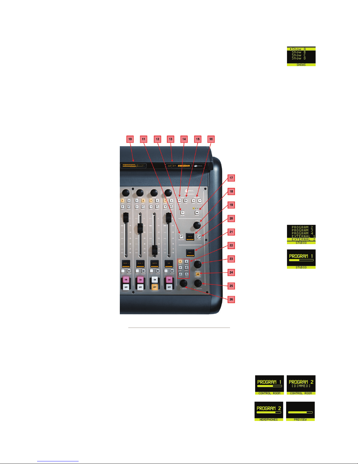
3: Console Operation • 26
13. Clock and Timer Display: This display in-
cludes both the Clock and the Timer. The Clock sec-
tions includes an NTP indicator that tells you when
the iQ synchronized to an external NTP clock refer-
ence. The Timer section displays the count-up timer
that may be controlled by fader-start or by the Timer
controls on the iQ.
14. Meter Key: If all four bus meters are not set
for constant display, this toggles the Soft (middle)
meter between Program
and Monitor metering.
15. Clock Key: Pressing
this key toggles between
AUTO and MANUAL
modes for the count-up
timer. AUTO allows it to
be reset and started by any
source starting that has
it’s timer start option en-
abled. MANUAL ignores
those starts and follows the
RUN/STOP/RESET keys
only. Note that even if you
are set to AUTO, the run/
stop/reset keys still work.
To set the clock, push and
hold the Clock key for 6
seconds to enter clock ad-
just mode. The Clock key
will illuminate indicating
Figure 3-4: iQ Main - Console Callouts
that clock setup is active.
Release the Clock key and
press RUN-STOP to set the clock display forward, and
press RESET to set it back. Press the Clock key again
to save the current time and exit clock adjust mode.
If NTP is active and enabled (via web page congura-
tion), the time cannot be adjusted manually.
16. Timer Controls: Pressing RESET zeroes the
count-up timer. Pressing the RU N/Sto p key manu-
ally starts or stops the count-up timer. The RUN/
Stop key illuminates while the timer
is running
17. Prole Key: This key allows you to select the
active iQ Show Prole from a group of four pre-con-
gured proles. The Studio OLED display tells you
which prole (A, B, C or D) is currently active. The
Studio Monitor knob is used to navigate this screen.
To exit this screen, press the Prole key. You can
also push and hold the prole key for 5 seconds to
reload the current prole.
18. STUDIO: “Stu-
dio” is dened here as an-
other room separate from the
Control Room, such as a talk
studio or news booth. Push-
ing this control selects the
Studio Monitor source; rotate
it to adjust the volume of the
Studio Monitor speakers. Note
that the Studio
monitors will
be muted when-
ever any Studio
Microphone is
turned ON.
19. STUDIO Monitor Dis-
play: This OLED display in-
dicates the volume and source
that is being delivered your
STUDIO monitors. This may
be changed with the STUDIO
control as described above.
20. TALK to STUDIO Key: This push-to-talk key
allows the operator to communicate with all Studio
guests simultaneously. The operator mic is routed
directly to Studio Head-
phone and Studio Moni-
tor outputs while this
key is pressed.
21. Control Room
© 2014 Axia Audio - Rev 1.3.1
Page 35

Monitor Display: This is a context sensitive
OLED display that indicates the volume and source
that is being delivered to your Con-
trol Room monitors, CR Head-
phones and Preview.
22. Control Room Monitor Select Keys: This
group of keys selects the source that is delivered to your
control room monitor speakers. The operator may se-
lect from PGM 1, PGM 2, PGM 3, PGM 4 or two pre-
designated external sources. The external sources are
typically used for off-air receivers and are specied
in the web page conguration.
External 1 and External 2 have another function, in
addition to their normal monitor-select action. If you
press and hold one of these keys for 2 seconds, you
will see that the Studio OLED display and Studio
Monitor knob may be used to assign a source on-the-
y to that specic External Input. Press Ext 1 or Ext
2 again to exit this Select mode.
23. PREVIEW Level Control: Adjusts the vol-
ume level of the Preview output connected to your
external powered PREVIEW speaker. Note that the
PREVIEW speaker will be muted whenever any CR
microphone is ON or when you are in Record mode.
24. PREVIEW in HEADPHONE Key: The H/P
PREV key controls whether audio from the Preview
bus will be fed to the board op’s headphones, and if
so, in what man ner. Pressi ng this key toggles through
the following options:
» Off: The operator will not hear Preview audio in
the headphone channel.
» ON (Stereo): audio from the Preview channel
overrides the Headphone Monitor selection
and is sent to both the left and right channels of
the operator’s headphones.
25. HEADPHONE Level Control: Rotate to adjust
the Headphone volume. Headphone source follows
CR Monitor selection.
26. MONITOR: Adjusts the level of your Con-
trol Room Monitors. This output will automatically
MUTE whenever any Control Room microphone is
ON or when Record Mode is active
System Settings
To acce ss System Settings from the iQ console, press
and hold the Meter and Clock keys for three seconds.
The Studio display shows the options and the Studio
Monitor control is used to navigate, select options and
change parameter values. Options available are:
» IP Address
» Subnet Mask
» Gateway
» Save and Reboot
To exit, select EXIT and press the Studio Monitor
control.
iQ 8-Fader Expansion Frame
Operation of the iQ 8-Fader frame is identical to that
of the faders on the iQ Main. As described in Chapter
2, fader number designations are determined by the
QOR.32 Console port to which the Frame is connected.
iQ 6-Fader+Telco Expansion Frame
The iQ 6-Fader+Telco frame includes faders plus
controls for a dual-hybrid telephone system. These con-
trols are specically designed to work with the Telos
iQ6 phone system, or with the Telos VX VoIP broadcast
phone system.
OLED Display: Call status (using exclusive Telos Status
Symbols icons) and other informa-
tion is presented on these context-
sensitive displays. Indications are:
» Line 1 is available
» Line 2 is on hold
» Line 3 is locked to Hybrid 1
with caller ID shown
» Line 4 is blocked
» Line 5 is selected and wait-
ing for digits to dial
» Line 6 is on-air on the fader to
the right of the button column.
3: Console Operation • 27
© 2014 Axia Audio - Rev 1.3.1
Page 36
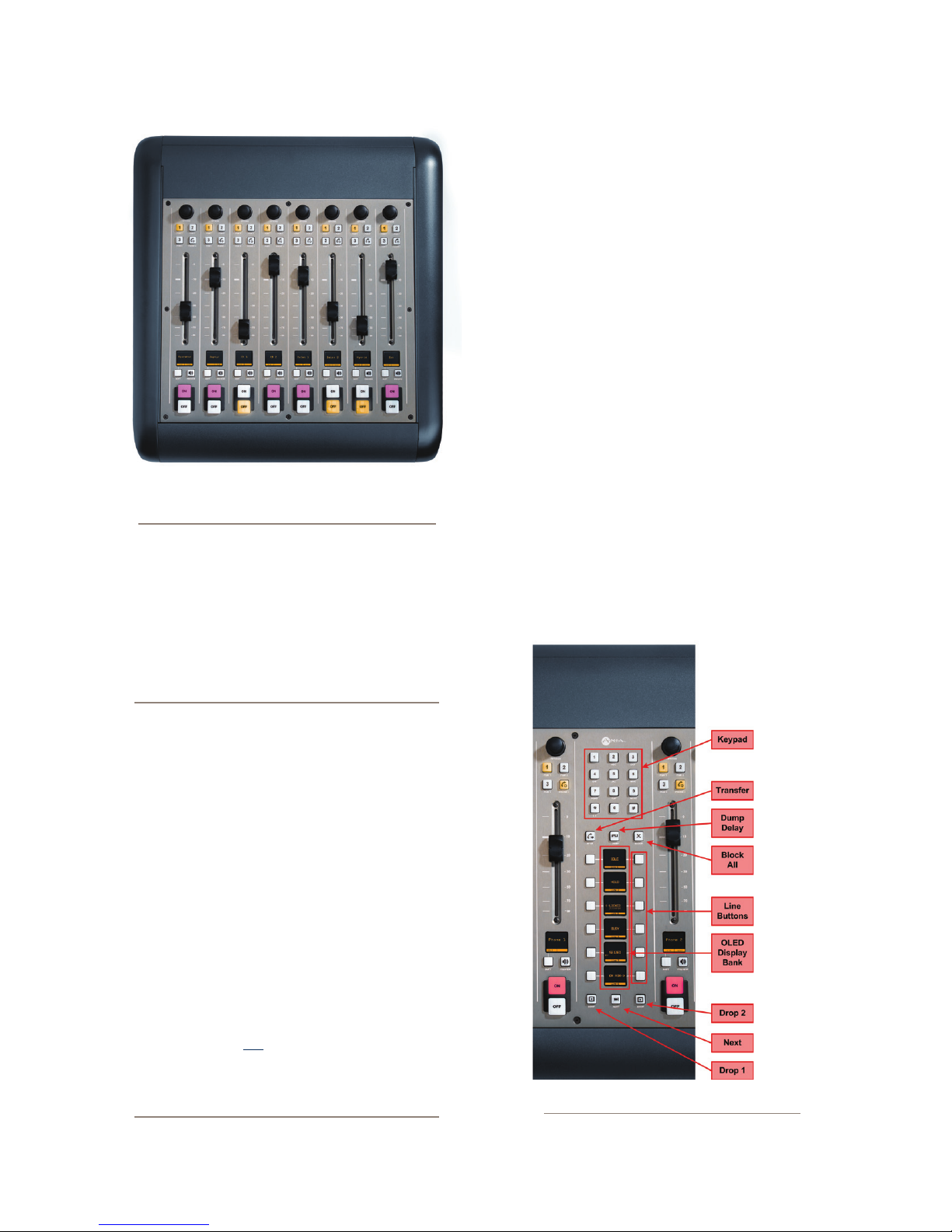
Keypad: Used for placing outbound phone calls
Transfer: Used to create a “hook ash” in POTS analog
phone systems. Depending on the way you’ve ordered
your Telco service, this key may serve to activate fea-
tures such as transfer or 3-Way Calling. This button does
not function with ISDN phone lines.
Delay Dump: This control triggers your external pro-
fanity delay using Livewire GPIO logic. The details of
this feature are still under development.
Block All: Pressing this key once will “busy” all phone
lines (except those that are on-air or on hold), thus block-
ing incoming calls. Pressing the key a second time will
release call blocking.
3: Console Operation • 28
Figure 3-6: iQ 8-Fader Frame
A completely dark display indicates that no line is con-
nected to that port. A “pulsating” display indicates a
ringing line.
If you’re familiar with Telos phone systems, you’ll nd
iQ’s hybrid controls to be very familiar indeed!
VoIP in the broadcast studio: Voice over IP
now dominates the telephone sector, so it’s only
natural for broadcasters to want to put VoIP to
work achieving better delity and call-handling
exibility in the radio studio. After all, tech-
nology that sounds this great shouldn’t be reserved just for the board room!
With broadcasters adopting IP-Audio as the “new
norm” for studio infrastructure, it makes sense
for the Telco to share the same IP-based studio
systems used for studio audio. This allows phone
systems to be integrated into the broadcast
console as never before, facilitating seamless
call-handling and even (dare we say it) interconnection between the business VoIP PBX and the
on-air phone system. iQ was designed with this
functionality in mind.
As a result, iQ requires a Telos iQ6 or a VXseries phone system to take advantage of this
advanced on-console phone integration. iQ’s hybrid controls are not compatible with older products, or those of other hybrid vendors, although
the outputs of these products may be assigned
to any fader and the phone system operated
with its own proprietary controller.
Line Buttons: Each line has 2 buttons, the left column
for Hybrid 1 and the right column for Hybrid 2. Pressing
a line button places the caller on that line on-air us-
ing the corresponding hybrid. Pressing a line button
when a call is already on-air locks the call on-air, pre-
Figure 3-7: iQ 6-Fader+Telco (partial view)
© 2014 Axia Audio - Rev 1.3.1
Page 37
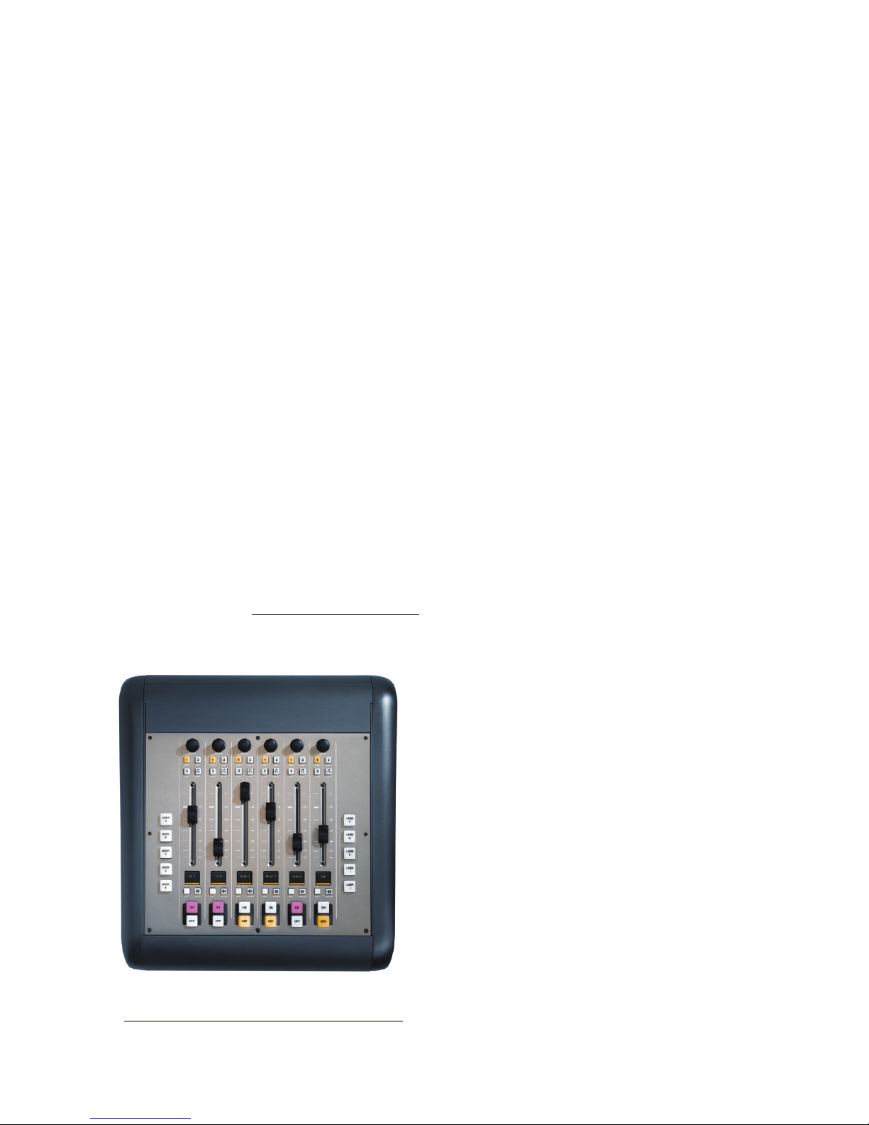
venting accidental disconnection. To unlock, press the
line button a third time.
Drop 1 and 2 Buttons: These buttons will drop calls
(in their respective column) that are currently on-air, if
that call is not in the “locked” state described above.
Next: Selects the line which has been ringing longest.
If no line is ringing, it selects the line that has been on
(normal) hold the longest.
Channel Soft Key: At this writing, the soft key on a fad-
er with a phone source assigned places the caller on hold.
iQ 6-Fader+User Keys Expansion Frame
The operation of faders found on this iQ 6-Fader
frame is identical to the operation of the individual fad-
ers that are found on the iQ Main. Please refer to the
callout descriptions for iQ Main in the previous section.
Each iQ 6-Fader+User Key frame also includes two
banks of User Keys. Each group consists of ve keys
that may be programmed as extensions of two of the iQ’s
GPIO ports. For information on conguring and using
these keys, please refer to Chapter 5: Conguring GPIO.
Source-Specific Channel Controls
Some fader functions change their behavior to suit
the type of source assigned to the fader. A Guest Mic in-
put has unique functions different from those of a Codec
input, and so forth. In this section we’ll explain the chan-
nel functions unique to each type of source input.
Control Room Operator Mic Channel
The Control Room Operator microphone is the board
operator’s mic. It’s always located in the Control Room,
so activating a channel designated as the CR Operator
mic affects CR Monitor speaker and Preview speaker
mut ing.
When the board operator pushes a Talkba c k key, all
output bus assignments for the Control Room Opera-
tor microphone are temporarily muted, while his mic’s
audio is routed to the requested Talk b ack destination.
Releasing the key returns the channel outputs to normal.
Pressing the channel ON key for the CR Operator
Mic while the channel is already on will mute the chan-
nel until the key is released, acting as a “cough” function
for the board operator. On-air status and speaker mutes
are unaffected by this action. The CR Operator micro-
phone channel will mute the CR Monitors (Monitor 1)
and the Preview speakers whenever the channel is On, or
if Preview or Record Mode Engage keys are selected.
Figure 3-8: IQ 6-Fader Module with User Keys
Producer Microphone Channel
The Producer’s microphone is meant to be used at
a position within the Control Room where a morning
show or talk show producer would normally sit. This
mic type mimics the operation of the Control Room mic
described above, but does not include the “cough” func-
tion; also, a Producer mic can use Talkback to talk to the
board op, but cannot talk directly to the Studio talkback
channel.
Control Room Guest Microphone Channel
There are often microphones in the Control Room
other than the board operator’s; i.e., an in-studio guest or
perhaps an announcer located physically near the board
op. These microphones also control the muting of the
© 2014 Axia Audio - Rev 1.3.1
3: Console Operation • 29
Page 38

3: Console Operation • 30
Control Room monitor speakers.
Control Room Guest Microphone channels will mute
the Control Room speakers and the Preview speakers
whenever the channel is ON, or if Preview key is se-
lected.
Studio Microphone Channel
Another type of microphone channel is a Studio
Microphone. This mic is typically located in a location
separate from the control room — perhaps a voice-over
booth, a talk studio separated by glass, or a news booth.
Logic for Studio Microphone channels is identical
to that of the Control Room Guest Microphone channel.
The Studio Monitor speakers mute when a Studio Mi-
crophone channel is turned on, or if it is assigned to the
Program-4/Record bus.
External Microphone Channel
This type of microphone operates identically to a
studio or CR guest microphone except that is does not
incorporate any monitor muting functions.
Line Channel
Line-level devices like CD players, tape players, etc.,
use the Line Channel prole. The Line Channel is ste-
reo, but the user can change the input mode to mono, left
only or right only by using the Pan & Mode key in the
Master Module’s Channel Options section.
Line channels have a variety of remote logic func-
tions available at the GPIO interface. ON and OFF keys
can be remotely controlled, as well as the Preview key.
Each function has a corresponding lamp driver.
You’ll also nd a Ready command which will re-
motely illuminate the OFF lamp on the IQ channel and
activate the GPIO OFF lamp driver, allowing source
equipment to signal the operator with either a steady-
state OFF key (indicating source ready) or a ashing
OFF lamp (indicating source next). Refer to the GPIO
Node User’s Manual for information on interfacing to
the GPIO’s inputs and outputs.
Phone Channel
The Phone Channel prole is used, naturally, for tele-
phone hybrid audio sources. Each Phone Channel has its
own discrete Feed-to-Source mix-minus output.
Each iQ can accommodate as many unique, automat-
ically-generated mix-minus feeds as it has faders. If the
Feed-to-Source mode is set to “Auto”, (the most common
option - see Chapter 2: iQ Inputs and Outputs for the
section entitled “Source Prole Options”), phone callers
hear the output of the Pr o gram-1 bus, minus himself,
when the channels they’re assigned to are ON. When the
caller’s channel is OFF, their channel’s Tal kbac k key is
lit and they hear the Board Operator’s mic routed to their
Tal kbac k feed.
Phone feed-to-source outputs can also be locked to
backfeed only PGM-1, PGM-2, PGM-3 or PGM-4, us-
ing the options provided when constructing the Source
Prole for your hybrid. This automatic switching mode
makes it very easy to prep callers and then seamlessly
take them to air with a minimum of key pushes.
Codec Channel
The Codec Channel is used for codec sources. Like
the Phone Channel, each codec source is brought up on
its own channel, and an individual Feed-to-Source (mix
minus) output is provided for each codec. Codec Chan-
nels can be turned on and off remotely and provide on/
off status to a remote logic device. Remote Talk and
Remote Mute are also provided, allowing talent to take
control using their own On/Off/Mute/Talk panels.
Tal k enables remote talent to communicate with the
board op using the Talk b ack bus. When Talk is activat-
ed, all outputs for that channel are muted and the source
audio is fed to the Tal kbac k bus; the channel’s OLED
displays TALK to CR. When the user stops talking, the
channel returns to normal.
When the operator uses the Softkey to talk to the
phone or codec source, the OLED displays TALKBACK.
When the remote mute function is activated, the
OLED displays MUTED and all the channel outputs are
muted until the command is released.
© 2014 Axia Audio - Rev 1.3.1
Page 39

The mix-minus output (congured in the Source
Prole section) normally feeds Prog ram -1 audio to
the remote, but can be switched to Program-2, 3, 4 or
Phone. The Feed-to-Source output on a Codec Channel
is a dual mono output, occupying both sides of the stereo
pair. The Left output is normally used for remote talent’s
headphone feed, and is interrupted by Talkb a ck audio
when the board op talks to the remote. The Right output
sends uninterrupted program audio (without talkback)
for use as a PA feed.
Remote Control
Console channels can be turned on and off remotely,
and will provide on/off status to a remote logic device.
Remote Preview is also provided, as are lamp drivers
for On, Off and Preview. Start and Stop pulses can be
sent when the channel is turned on or off, respectively.
See Chapter 5: Conguring GPIO for detailed infor-
mation interfacing to GPIO inputs and outputs.
What’s Next
Now that you know how what all the controls do,
let’s get acquainted with one of iQ’s most powerful func-
tions: Show Proles.
3: Console Operation • 31
© 2014 Axia Audio - Rev 1.3.1
Page 40

D igt res
re ler DJs?
J Brary nws.
3: Console Operation • 32
© 2014 Axia Audio - Rev 1.3.1
Page 41

Chapter Four:
channel with a pending source change will immediately load the waiting source.
Show Profiles
If you’ve read Chapter 2: Inputs and Outputs, you
already have a good understanding of Source Proles.
In the same way that Source Proles allow you to de-
termine how an individual channel is congured when
a source is loaded to a fader, Show Proles let you build
conguration les that determine how the entire console
behaves, which sources are loaded, and what channels
they appear on — “snapshots” that you can load at will
to recall baseline show settings.
For instance, you could use Show Proles as a “re-
turn to zero” command. iQ is highly customizable; jocks
can might load new sources, change EQ or make other
adjustments during their show. A Show Prole can reset
the console to its default state for the next operator.
Or, you could use Show Proles to dene different
types of broadcasts – one for the morning show, one for
talk segments, one for musical guest interviews, one for
unattended operation – that need only to be loaded to
instantly optimize the board for use with that situation.
You can save and recall up to four unique Show Pro-
les to customize your iQ for different users or shows.
Important note about using Show Proles:
If you load a new Show Prole while any channels are still ON, those channels will remain in
their current state - that is, any new source that
is assigned to that channel by the Show Prole
will not be loaded - until the channels are turned
OFF, at which time, the new source will load for
that channel. This is to prevent operators from
accidentally taking an active source off the air.
This also enables operators to load a new Show
Prole a few minutes prior to needing it, secure
in the knowledge that any sources that are ON
will not be affected. Note that this notication
will be given even if the “new” source is the
same as the one currently on-air.
The surface will signal the operator that a source
change is pending by blinking the OFF button and displaying the message Src Waiting
on that channel’s OLED display. Turning OFF a
Creating A Show Profile
Build A Show
iQ’s Web interface, which you’ve used to construct
Source Proles, is also used to help build Show Proles,
so make sure a computer connected to your QOR.32 or
Livewire network is within easy reach.
Your iQ is shipped from the factory with a default
Show Prole. This loads the rst time you turn on your
iQ; it provides the “template” you’ll use to construct cus-
tom Show Proles. You’ve no doubt been exploring your
iQ, so you might want to reload Default Show Prole
A with the Prole key located in the iQ Master section.
Simply press and hold the A key and, after a few seconds,
the default prole will load, resetting the mixing surface
to its factory state.
The rst step in building a Show Prole is to set
up iQ using the Channel Options, Monitor, Headphone,
Studio and other board options as described in Chapter
3: iQ Operations. Get started by assigning a source to
each iQ fader using the Options knobs at the top of each
channel.
After you’ve assigned a source for each fader, you
can congure the rest of the Channel Options:
• Gain,
• Pan / Balance,
• Feed to Source.
When you’ve congured all Channel Options, con-
tinue on and make monitor and headphone selections
since these are all saved in Show Proles as well.
When you’ve got the board congured to your satis-
faction, proceed to the next section.
Capture It!
It’s now time to save your iQ conguration as a Show
Prole. Enter your iQ’s IP address in your Web browser.
When the Main Menu appears, choose Shows on the
4: Show Proles • 33
© 2014 Axia Audio - Rev 1.3.1
Page 42
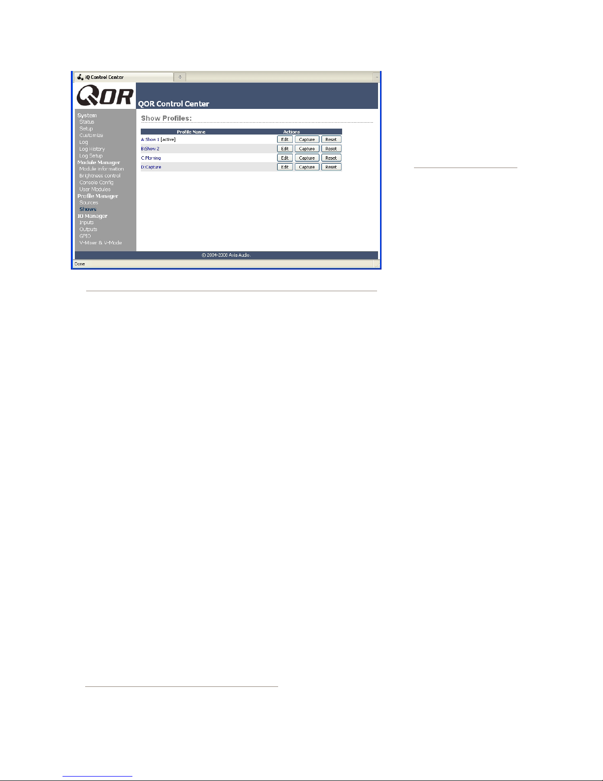
Figure 4-1: Show Proles screen
sidebar menu. This is where you’ll come whenever you
need to capture, construct or administer a Show Prole.
Under the Show Proles list, you’ll nd four proles
listed with three options for each Show Prole:
• Edit. Choose this option to manually edit any ex-
isting show proles.
• Capture. Takes a “snapshot” of the current iQ
console state and saves it for recall. This is the op-
tion we’ll use in just a moment.
• Reset. Choose this option when you want to
construct an entire Show Prole completely from
scratch and reset all parameters to their default
state or value.
tions to assign sources
and set monitor options.
Let them set up the board
exactly the way they want it,
then use the Capture command to save their work. This
way, talent gets the satisfaction of per sonalizing their
own iQ conguration — and
saves you the work!
Show Profile Options
Although the ability to cre-
ate Show Proles using the “cap-
ture” function is powerful, there
are a few more options available
exclusively via the iQ Web inter-
face. You will probably nd that
a combination of console setup, capture and edit works
best.
When you select any Show Prole, you will enter the
edit screen as shown in Figure 4-2. Notice that there is a
section for your iQ faders, as well as sections for Phone,
Monitors, External Inputs and some general User Inter-
face settings. At the very top of the page is the Show
Name. Use this to give the Prole a descriptive appel-
lation
We will now look at the individual Show Prole set-
tings in detail.
You’ve already set up your iQ, so now you can just
“capture” your settings for further use. Choose Capture
from the menu. iQ allows you to capture up to four Show
Proles which are saved as A, B, C and D. You may also
give meaningful names to these Show Proles as de-
scribed in the next section.
There may be a few more options you’d like to tweak,
since not all options are accessible from iQ console itself.
Let’s go a little deeper into Show Proles to nd out ex-
actly what’s available to you.
Suggestion: As part of iQ training, show
4: Show Proles • 34
your talent how to use the Channel Op-
Fader Channels
This section has settings for each fader channel.
When this specic Show Prole is loaded, these settings
will be applied.
• SOURCE: You can change the source using the drop-
down box. The name of the source you assign will be
displayed on the OLED below the fader.
• ON/OFF: Species the channel ON/OFF state when
the prole is loaded.
• PGM1/2/3/4 : Determines the default bus assign-
ments for this channel when the Show Prole is load-
ed. When a check-box is selected, the source will be
assigned to the corresponding bus.
• Group Start: There are three possible settings:
© 2014 Axia Audio - Rev 1.3.1
Page 43
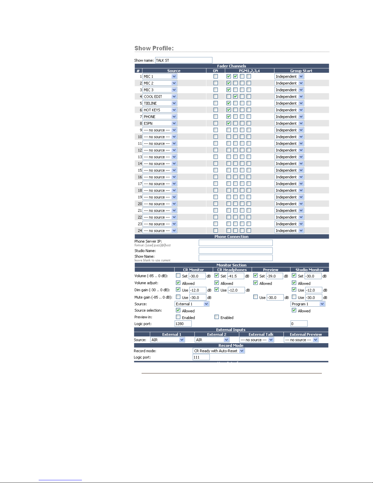
» Independent - this fader
is not associated with any
other fader and operates
independently
» Master - is used to select
one fader as the master for
group starts.
» Slave - is used to select
one or more faders as
Slaves that will follow the
action of the fader that has
been designated as the
Master.
Phone Connection
This section contains the set-
tings for connection to your iQ6
or Telos VX phone system. (Of
course, you can also connect your
iQ to any stand-alone hybrid by
using the inputs and outputs on
the QOR.32, but the settings con-
tained in this section function only
with iQ6 or VX phone systems.)
Note that the iQ phone source
proles contain settings that are
used to specify individual back-
feeds and hybrid channels for all
types of phone systems.
• Phone Server IP: Speci-
es your user name and the
IP address of your iQ6 or
Telos VX phone server. Log-
in information is in the for-
mat: user:pass@ip. For ex-
ample, if your VX user name
is Marty and your password
is “C185”, you would enter
Marty:[email protected] where 192.168.0.123
is the IP address of your phone server.
• Studio Name: This is your studio name, as cong-
ured in the VX system.
• Show Name: This can be the same as your iQ show
prole for consistency but it must correspond to a
Show Name congured in your VX phone system.
Figure 4-2: Show Prole Options
If you leave this blank, the current VX show will re-
main in use.
Monitor Section
• Volume (-85..0 dB): You may specify initial vol-
ume settings for the outputs listed below. The default
setting is full mute:
4: Show Proles • 35
© 2014 Axia Audio - Rev 1.3.1
Page 44

4: Show Proles • 36
» CR Monitor
» CR Headphones
» Preview
» Studio Monitor
• Volume Adjust: This checkbox determines whether
you will permit the operator to change the volume
settings for the outputs listed below — useful for
locking a console into a certain state during unat-
tended operation. “Allowed” is checked by default.
» CR Monitor
» CR Headphones
» Preview
» Studio Monitor
• Dim Gain (-30..0 dB): You may adjust the Dim
Gain independently for CR Monitor, CR Headphones
and Studio Monitor. This determines the amount of
dimming that will be applied when Talkback is di-
rected to one of these outputs. The default setting is
-12.0 dB.
• Mute Gai n (-85 . . 0 dB): You can specify the amount
of attenuation that takes place during a Mute func-
tion. The default is full mute. Mute can be applied to
CR monitor, Preview and Studio Monitor but it is not
applied to CR Headphones.
• Source: Selects the default source for CR Monitor
and Studio Monitor. Available options are Program
1/2/3/4 and External 1/2.
• Source Selection: You may prevent the operator or
studio talent from changing their CR Monitor or Stu-
dio Monitor source if the corresponding “Allowed”
check box is unchecked.
• Preview In: determines whether or not Preview will
be heard in CR Monitor or CR Headphones in addi-
tion to the Preview speaker.
• Logic Port: Use this to specify the Livewire channel
number assigned to logic ports (GPIO) used for CR
Monitor and Studio Monitor functions. These GPIO
ports are used for on-air lights and other functions as
described in the GPIO tables. Please refer to Chap-
ter 5: Conguring GPIO for more details.
External Inputs
• Source: Lets you specify two External sources for
monitoring purposes plus one source that is an Ex-
ternal Preview source. Note that the drop-down se-
lector displays all sources that have been dened as
iQ sources in the Source Prole manager.
What’s External Preview for? “External” refers here to any source not generated inside the
studio you’re working in. Let’s say you have a
Talkback source that you want to feed to the
console’s Preview speaker. To do this, you would
setup a source prole for the Talkback audio and
specify that source as External Preview
User Interface
Several global settings are dened in this section.
Remember that even though these are general settings,
they are specic to each Show Prole so you may ac-
commodate the unique requirements of different shows.
• Timer Mode: is used to specify the default timer
mode - manual or automatic. In automatic, the timer
may be started by turning a channel ON.
• Preview Interlock Mode: If Enable is checked,
pressing any fader’s Preview key causes any other,
previously-lit Preview key to be extinguished, re-
moving that source from Preview. The board opera-
tor can assign multiple faders to Preview by pushing
and holding any lit Preview key while pushing other
Preview keys to add or subtract. If unchecked, each
Preview key works like a press-on, press-off latching
switch. Multiple faders can be assigned to Preview
simply by pushing once; a second push cancels any
individual Preview assignment.
• Switchable Meter Source: The right half of the
second OLED display is a switchable meter. The
desired default may be selected from the drop-down
menu. Choices are: Program 4 or Follow Monitor.
• Logic Port for Timer: Enter the Channel Number
of the GPIO port you wish to use for external control
of your Count-Up timer.
• Talk to CR Level: Use up to -30 dB attenuation or
10 dB gain on the contents of the Talkba c k bus.
• Control Lock Map: This section includes several
check boxes. When a box is checked, the selected
actions are allowed. Any unchecked boxes will pro-
hibit the operator from accessing these functions
when this Show Prole is loaded. The selections are:
© 2014 Axia Audio - Rev 1.3.1
Page 45

» Meter Source
» Timer Mode
» Timer Controls
» Record Mode
» Talk to backfeeds
» Talk to Studio
» Preview in HP
As usual, please remember to hit Apply when you
are done to save your changes.
Record Mode
Record mode has four options:
» Disabled (default)
» Enabled
» CR Ready
» CR Ready with Auto Reset.
These options control the function of the Record key.
If any option but Disabled is selected, a unique Livewire
channel number must be assigned to the Logic port eld.
When enabled, logic follows the Record Device
GPIO table found in the GPIO chapter of this manual.
CR Ready simply enables the rst pin on the logic port
when the record button is pressed; CR Ready with Auto
Reset does the same, but the pin resets once a micro-
phone is turned on.
External Talk
If the console is installed in a Control Room where
the operator will not go “live” with a mic, this option
saves you from the need to assign the Operator Mic
source type to a fader for Talkback to Codecs or Phones.
Assign the appropriate source to External Talk, and with
no Operator mic loaded to a channel, the operator can
still engage Talk functions to backfeeds.
What’s Next?
We have mentioned GPIO many times in the preced-
ing chapters. Join us in Chapter 5 to learn how to inter-
face the logic functions of your iQ console with the real
world.
© 2014 Axia Audio - Rev 1.3.1
4: Show Proles • 37
Page 46

t thsn tngs
H lng d t r? Gt
n RCA, gn.
4: Show Proles • 38
© 2014 Axia Audio - Rev 1.3.1
Page 47

GPIO Port Definitions
Chapter Five:
Configuring GPIO
Since the days of rotary-switch source selectors, it’s
been a challenge to properly route machine logic along
with audio. Some complicated schemes have been de-
vised over the years, but broadcasters wanted a simple,
fast way to associate logic with audio in a routable en-
vironment.
Since the Axia IP-Audio system was designed as a
true computer network, we were able to start with a clean
sheet of paper to design the rst truly routable machine
logic/audio interface. Unlike conventional logic connec-
tions which require each command circuit to be wired
individually, Axia sends machine controls over the same
Ethernet your audio travels on, further reducing infra-
structure, cost and tedium.
The QOR.32 has eight DB-15 connectors on its back
panel. Each connector (also known as a GPIO port) can
be associated with a device in your studio, and provides
ve opto-isolated inputs and ve opto-isolated outputs
per device for machine control, lamp drives and remote
channel controls. GPIO ports can also be monitored and
controlled by our PathnderPC software.
GPIO ports are programmed to support several dif-
ferent types of devices. How does a GPIO port “know”
which type of device is assigned to it?
Back in Chapter 2, when you constructed a Source
Prole for a telephone hybrid, you dened the source
type (see “Adding Backfeeds and GPIO to a Source
Prole”). This is important, because when that source
is assigned to a console fader, iQ uses this Source Prole
selection to tell the GPIO Node what sort of command
to send to the attached device.
Along with controlling external audio devices, iQ
GPIO (General Purpose Input/Output) interface also in-
cludes logic commands for routine studio/control room
operations such as tally lights, monitor muting, On-Air
lights and more.
The last chapter explained source proles and
showed you how you can associate GPIO with a source.
This chapter explains how to set up iQ GPIO to handle
these functions. We also invite you to read the GPIO
Node User’s Manual, for more in-depth information on
the topic of GPIO.
Note: The iQ console is used with a QOR.32 that
includes eight GPIO ports. GPIO ports on standalone GPIO nodes or other Axia consoles may
also be associated with your iQ sources if your
iQ is a part of a larger network. See Chapter 7:
Livewire Networks and iQ for details.
If iQ “sees” in the Source Prole that the assigned
device is a microphone, it tells the GPIO Node to send
logic for
commands on the appropriate pins. If it “sees” a line
input, it tells the GPIO Node to send Start, Stop and
Reset commands, plus closures for Ready lights, etc.
for the following types of devices:
function the pins provide in each different device mode.
On, Off, Remote Mute and Remote Talk
Axia GPIO ports can deliver unique command sets
1. Mic (Operator, Guest, Producer)
2. Line Input
3. Codec
4. Telephone Hybrid
5. Computer Playback Device
6. Control Room Monitor
7. Studio Monitor
8. Profanity Delay Device
9. Recording Device
10. Accessory Button Panel Device
The next few pages contain tables that explain what
5: Conguring GPIO • 39
© 2014 Axia Audio - Rev 1.3.1
Page 48
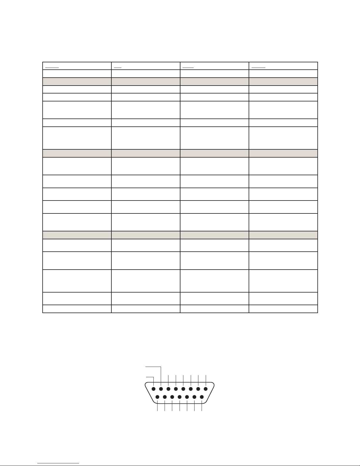
GPIO Operator’s Microphone Logic
+
SOURCE
Name Pin Typ e Notes
INPUTS
ON Command 11 Active L ow Input Turns channel ON
OFF Command 12 Active Low Input Turn channel OFF
TALK (to Monitor 2) Command 13 Active L ow Input Activates the TALK TO MON2
MUTE Command 14 Active Low Input Mutes channel outputs
TALK (to PREVIEWED
15 Active Low Input Activates the TALK button
SOURCE) Command
OUTPUTS
ON Lamp 1 Open Collector to Logic Com-
mon Return
OFF Lamp 2 Open Collector to Logic Com-
mon Return
TALK (to Monitor 2) Lamp 3 Open Collector to Logic Com-
mon Return
MUTE Lamp 4 Open Collector to Logic Com-
mon Return
TALK (to PREVIEWED
SOURCE) Lamp
5 Open Collector to Logic Com-
mon Return
POWER & COMMON
Source Common 7 Logic Common Connect to ground of source
Logic Common 8 Internal 5 Volt r eturn Can be connected to Pin 7
Logic +5 Volt Supply 9 Logic Supply, Individually
Fused
Input Common 10 Common for all 5 inputs Connect to power supply of
NOT CONNECTED 6
function and routes mic audio
to the Talkback bus.
on every source currently in
preview and routes mic audio
to the Talkback bus.
Illuminates when channel is
ON unless TALK or MUTE is
active
Illuminates when channel is
OFF
Illuminate s when TALK TO
MON2 is active
Illuminate s when MUTE is
active
Illuminate s when TALK to
PREVIEWED SOURCE is active.
device or to Pin 8
if source is not providing
common
Can be connected to Pin 10 if
source is not providing voltage; active only when source
has been assigned to channel.
source device or to Pin 9
5: Conguring GPIO • 40
OUTPUT
COMMON
RETURN
ØV (GND)
SOURCE
OUT
5
8 7 6 5 4 3 2 1
15 14 13 12 11 10 9
IN5IN4IN3IN2IN1IN
OUT
OUT
OUT
OUT
2
3
4
+5 V
POWER
COM
© 2014 Axia Audio - Rev 1.3.1
1N/C
GPIO v.”ZA” 4/2009
Page 49
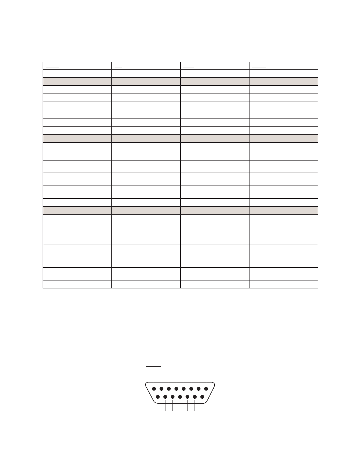
GPIO Control Room Guest Microphone Logic
+
SOURCE
Name Pin Typ e Notes
INPUTS
ON Command 11 Active L ow Input Turns channel ON
OFF Command 12 Ac tive Low Input Turn channel OFF
TALK (to CR) Command 13 Active Low Input Mutes channel outputs and
MUTE Command 14 Active Low Input Mutes channel outputs
NOT CONNECTED 15
OUTPUTS
ON Lamp 1 Open Collector to Logic Com-
mon Return
OFF Lamp 2 Open Collector to Logic Com-
mon Return
TALK (to CR) Lamp 3 Open Collector to Logic Com-
mon Return
MUTE Lamp 4 Open Collector to Logic Com-
mon Return
NOT CONNECTED 5
POWER & COMMON
Source Common 7 Logic Common Connect to ground of source
Logic Common 8 Internal 5 Volt r eturn Can be connected to Pin 7
Logic + 5 Volt supply 9 Logic Supply, Individually
Fused
Source Supply 10 Common for all 5 inputs Connect to power supply of
NOT CONNECTED 6
routes source audio to PVW
speakers
Illuminates when channel is
ON unless TALK or MUTE is
active
Illuminates when channel is
OFF
Illuminate s when TALK is
active
Illuminate s when MUTE is
active
device or to Pin 8
if source is not providing
common
Can be connected to Pin 10 if
source is not providing voltage; active only when source
has been assigned to channel.
source device or to Pin 9
OUTPUT
COMMON
RETURN
ØV (GND)
SOURCE
OUT
5
8 7 6 5 4 3 2 1
15 14 13 12 11 10 9
IN5IN4IN3IN2IN1IN
OUT
OUT
OUT
2
3
4
+5 V
POWER
COM
© 2014 Axia Audio - Rev 1.3.1
OUT
1N/C
GPIO v.”ZA” 4/2009
5: Conguring GPIO • 41
Page 50
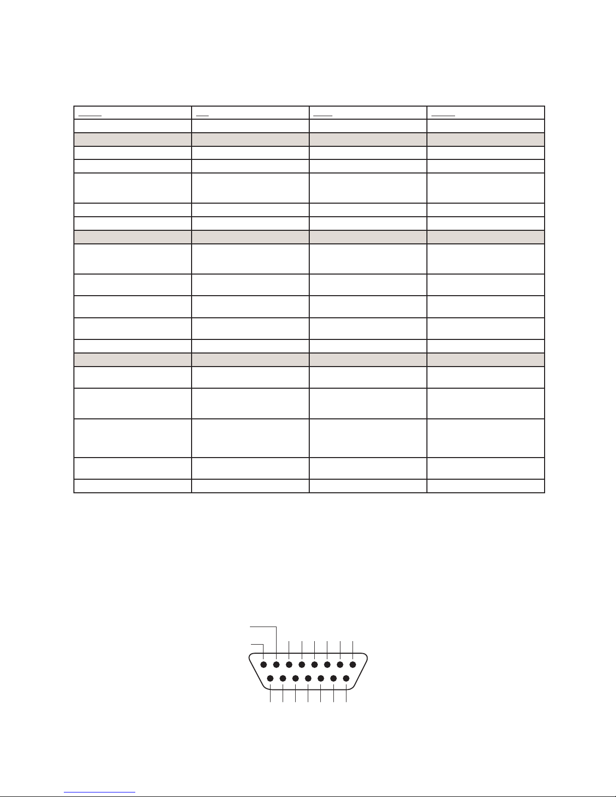
GPIO Studio (Monitor 2) Guest Microphone Logic
Name Pin Typ e Notes
INPUTS
ON Command 11 Active L ow Input Turns channel ON
OFF Command 12 Ac tive Low Input Turn channel OFF
TALK (to CR) Command 13 Active Low Input Mutes channel outputs and
MUTE Command 14 Active Low Input Mutes channel outputs
NOT CONNECTED 15
OUTPUTS
ON Lamp 1 Open Collector to Logic Com-
mon Return
OFF Lamp 2 Open Collector to Logic Com-
mon Return
TALK (to CR) Lamp 3 Open Collector to Logic Com-
mon Return
MUTE Lamp 4 Open Collector to Logic Com-
mon Return
NOT CONNECTED 5
POWER & COMMON
Source Common 7 Logic Common Connect to ground of source
Logic Common 8 Internal 5 Volt r eturn Can be connected to Pin 7
Logic + 5 Volt supply 9 Logic Supply, Individually
Fused
Source Supply 10 Common for all 5 inputs Connect to power supply of
NOT CONNECTED 6
routes source audio to PVW
speakers
Illuminates when channel is
ON unless TALK or MUTE is
active
Illuminates when channel is
OFF
Illuminate s when TALK is
active
Illuminate s when MUTE is
active
device or to Pin 8
if source is not providing
common
Can be connected to Pin 10 if
source is not providing volt-
age; active only when source
has been assigned to channel.
source device or to Pin 9
5: Conguring GPIO • 42
OUTPUT
COMMON
RETURN
ØV (GND)
SOURCE
OUT
5
8 7 6 5 4 3 2 1
15 14 13 12 11 10 9
IN5IN4IN3IN2IN1IN
OUT
OUT
OUT
OUT
2
3
4
+5 V
COM
POWER
+
SOURCE
© 2014 Axia Audio - Rev 1.3.1
1N/C
GPIO v.”ZA” 4/2009
Page 51
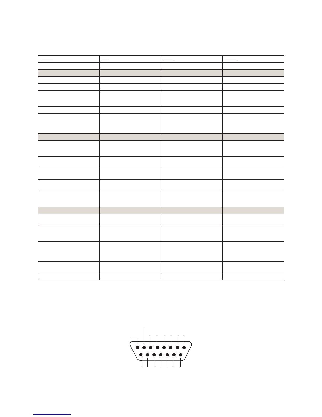
GPIO Producer’s Microphone Logic
Name Pin Typ e Notes
INPUTS
ON Command 11 Active L ow Input Turns channel ON
OFF Command 12 Ac tive Low Input Turn channel OFF
TALK (to MONITOR 2)
Command
MUTE Command 14 Active Low Input Mutes channel outputs
TALK (to PREVIEWED
SOURCE) Command
OUTPUTS
ON Lamp 1 Open Collector to Logic Com-
OFF Lamp 2 Open Collector to Logic Com-
TALK (to MONITOR 2) Lamp 3 Open Collec tor to Logic Com-
MUTE Lamp 4 Open Collector to Logic Com-
TALK (to PREVIEWED
SOURCE) Lamp
POWER & COMMON
Source Common 7 Logic Common Connect to ground of source
Logic Common 8 Internal 5 Volt r eturn Can be connected to Pin 7
Logic + 5 Volt supply 9 Logic Supply, Individually
Source Supply 10 Common for all 5 inputs Connect to power supply of
NOT CONNECTED 6
13 Ac tive Low Input Activates the TALK to MON2
function and routes mic audio
to the Talkback bus.
15 Active Low Input Activates the TALK button
on every source currently in
Preview and routes mic audio
to the Talkback bus.
Illuminates when channel is
mon Return
ON unless TALK or MUTE is
active
Illuminates when channel is
mon Return
OFF
Illuminate s when TALK to
mon Return
MON2 is active.
Illuminate s when MUTE is
mon Return
5 Open Collector to Logic Com-
mon Return
active
Illuminate s when TALK to
PREVIEWED SOURCE is active.
device or to Pin 8
if source is not providing
common
Can be connected to Pin 10 if
Fused
source is not providing voltage; active only when source
has been assigned to channel.
source device or to Pin 9
OUTPUT
COMMON
RETURN
ØV (GND)
SOURCE
OUT
5
8 7 6 5 4 3 2 1
15 14 13 12 11 10 9
IN5IN4IN3IN2IN1IN
OUT
OUT
OUT
2
3
4
+5 V
COM
POWER
+
SOURCE
© 2014 Axia Audio - Rev 1.3.1
OUT
1N/C
GPIO v.”ZA” 4/2009
5: Conguring GPIO • 43
Page 52
GPIO Line Input Logic
+
SOURCE
Name Pin Type Notes
INPUTS
ON Command 11 Active Low Input Turns channel ON
OFF Command 12 Active Low Input Turns channel OFF & sends
PREVIEW Command 13 Active Low Input Turns preview ON
RESET Command 14 Active Low Input Turns channel OFF, while not
READY Command 15 Ac tive Low Input Illuminates OFF lamp to indi-
OUTPUTS
ON Lamp 1 Open Collector to Logic Com-
mon Return
OFF Lamp 2 Open Collector to Logic Com-
mon Return
PREVIEW Lamp 3 Open Collector to Logic Com-
mon Return
START Pulse 4 Open Collector to Logic Com-
mon Return
STOP Pulse 5 Open Collector to Logic Com-
mon Return
POWER & COMMON
Source Common 7 Logic Common Connect to ground of source
Logic Common 8 Internal 5 Volt return Can be connected to Pin 7 if
Logic + 5 Volt supply 9 Logic Supply, Individually
Fused
Source Supply 10 Common for all 5 inputs Connect to power supply of
NOT CONNECTED 6
100 msec STOP pulse
sending a STOP pulse
cate source’s readiness
Illuminates when channel is
ON
Illuminates when channel is
OFF and READY is ac tive
Illuminates when PREVIEW
is ON
A 100 msec pulse when the
channel status changes from
OFF to ON
A 100 msec pulse when the
channel status changes from
ON to OFF
device or to Pin 8
source is not providing common
Can be connected to Pin 10
if source is not providing
voltage; active only when
source has been assigned to
channel.
source device or to Pin 9
5: Conguring GPIO • 44
OUTPUT
COMMON
RETURN
ØV (GND)
SOURCE
OUT
5
8 7 6 5 4 3 2 1
15 14 13 12 11 10 9
IN5IN4IN3IN2IN1IN
OUT
OUT
OUT
OUT
2
3
4
+5 V
POWER
COM
© 2014 Axia Audio - Rev 1.3.1
1N/C
GPIO v.”ZA” 4/2009
Page 53
GPIO Codec Logic
+
SOURCE
Name Pin Type Notes
INPUTS
ON Command 11 Active Low Input Turns channel ON
OFF Command 12 Active Low Input Turns channel OFF
TALK (to CR) Command 13 Active L ow Input Mutes channel outputs and
MUTE Command 14 Active Low Input Mutes channel outputs
TALK (to SOURCE) Command 15 Active Low Input Allows an ex ternal button
OUTPUTS
ON Lamp 1 Open Collector to Logic Com-
mon Return
OFF Lamp 2 Open Collector to Logic Com-
mon Return
TALK (to CR) Lamp 3 Open Collector to Logic Com-
mon Return
MUTE Lamp 4 Open Collector to Logic Com-
mon Return
TALK (to SOURCE) Lamp 5 Open Collector to Logic Com-
mon Return
POWER & COMMON
Source Common 7 Logic Common Connect to ground of source
Logic Common 8 Internal 5 Volt return Can be connected to Pin 7 if
Logic + 5 Volt supply 9 Logic Supply, Individually
Fused
Source Supply 10 Common for all 5 inputs Connect to power supply of
NOT CONNECTED 6
routes source audio to PVW
speakers
to activate channel TALK TO
SOURCE function.
Illuminates when channel is
ON unless TALK or MUTE are
active
Illuminates when channel is
OFF.
Illuminate s when TALK is
active
Illuminate s when MUTE is
active
Illuminates when the channel
TALK TO SOURCE function is
active.
device or to Pin 8
source is not providing common
Can be connected to Pin 10
if source is not providing
voltage; active only when
source has been assigned to
channel.
source device or to Pin 9
OUTPUT
COMMON
RETURN
ØV (GND)
SOURCE
OUT
5
8 7 6 5 4 3 2 1
15 14 13 12 11 10 9
IN5IN4IN3IN2IN1IN
OUT
OUT
OUT
2
3
4
+5 V
POWER
COM
© 2014 Axia Audio - Rev 1.3.1
OUT
1N/C
GPIO v.”ZA” 4/2009
5: Conguring GPIO • 45
Page 54
GPIO Telephone Hybrid Logic
+
SOURCE
Name Pin Type Notes
INPUTS
ON Command 11 Active Low Input Turns channel ON
OFF Command 12 Active Low Input Turns channel OFF
PREVIEW Command 13 Active Low Input Turns preview ON
RESET Command 14 Active Low Input Turns channel off while not
READY Command 15 Ac tive Low Input Illuminates OFF lamp to indi-
OUTPUTS
ON Lamp 1 Open Collector to Logic Com-
mon Return
OFF Lamp 2 Open Collector to Logic Com-
mon Return
PREVIEW Lamp 3 Open Collector to Logic Com-
mon Return
START Pulse 4 Open Collector to Logic Com-
mon Return
STOP Pulse 5 Open Collector to Logic Com-
mon Return
POWER & COMMAND
Source Common 7 Logic Common Connect to ground of source
Logic Common 8 Internal 5 Volt return Can be connected to Pin 7 if
Logic + 5 Volt supply 9 Logic Supply, Individually
Fused
Source Supply 10 Common for all 5 inputs Connect to power supply of
NOT CONNECTED 6
sending a STOP pulse
cate source’s readiness
Illuminates when channel is
ON
Illuminates when channel is
OFF
Illuminates when PREVIEW
is ON
A 100 ms PULSE is sent when
channel is rst turned ON or
when PV W is rst selected
A 100 ms PULSE sent when
channel is turned OFF.
device or to Pin 8
source is not providing common
Can be connected to Pin 10
if source is not providing
voltage; active only when
source has been assigned to
channel.
source device or to Pin 9
5: Conguring GPIO • 46
OUTPUT
COMMON
RETURN
ØV (GND)
SOURCE
OUT
5
8 7 6 5 4 3 2 1
15 14 13 12 11 10 9
IN5IN4IN3IN2IN1IN
OUT
OUT
OUT
OUT
2
3
4
+5 V
POWER
COM
© 2014 Axia Audio - Rev 1.3.1
1N/C
GPIO v.”ZA” 4/2009
Page 55
GPIO Control Room Monitor Logic
+
SOURCE
Name Pin Type Notes
INPUTS
MUTE CR Command 11 Active Low Input Mutes CR monitors and Pre-
DIM CR Command 12 Active Low Input Allows external dimming of
Enable EXT PREVIEW Com-
13 Active Low Input Feeds External Audio Input to
mand
TALK TO EX T Command 14 Active Low Input Turns on Talk to Exter nal
Not used. 15 Active Low Input
OUTPUTS
CR ON AIR L amp 1 Open Collector to Logic Com-
mon Return
DIM CR Lamp 2 Open Collector to Logic Com-
mon Return
PREVIEW Lamp 3 Open Collector to Logic Com-
mon Return
TALK TO EX T Lamp 4 Open Collec tor to Logic Com-
mon Return
TALK (to CR) Active Lamp 5 Open Collector to Logic Com-
mon Return
POWER & COMMON
Source Common 7 Logic Common Connect to ground of source
Logic Common 8 Internal 5 Volt return Can be connected to Pin 7 if
Logic + 5 Volt supply 9 Logic Supply, Individually
Fused
Source Supply 10 Common for all 5 inputs Connect to power supply of
NOT CONNECTED 6
view speakers
CR monitor speakers.
PREV IEW
Audio.
Illuminate s whenever CR
monitors are muted
Illuminate s whenever control
room monitors are DIMMED
Illuminate s when PREVIE W is
active.
Illuminate s when Talk to
External is active.
Active whenever a source has
activated its TALK (to CR)
function
device or to Pin 8
source is not providing common
Can be connected to Pin 10
if source is not providing
voltage; active only when
source has been assigned to
channel.
source device or to Pin 9
OUTPUT
COMMON
RETURN
ØV (GND)
SOURCE
OUT
5
8 7 6 5 4 3 2 1
15 14 13 12 11 10 9
IN5IN4IN3IN2IN1IN
OUT
OUT
OUT
2
3
4
+5 V
POWER
COM
© 2014 Axia Audio - Rev 1.3.1
OUT
1N/C
GPIO v.”ZA” 4/2009
5: Conguring GPIO • 47
Page 56
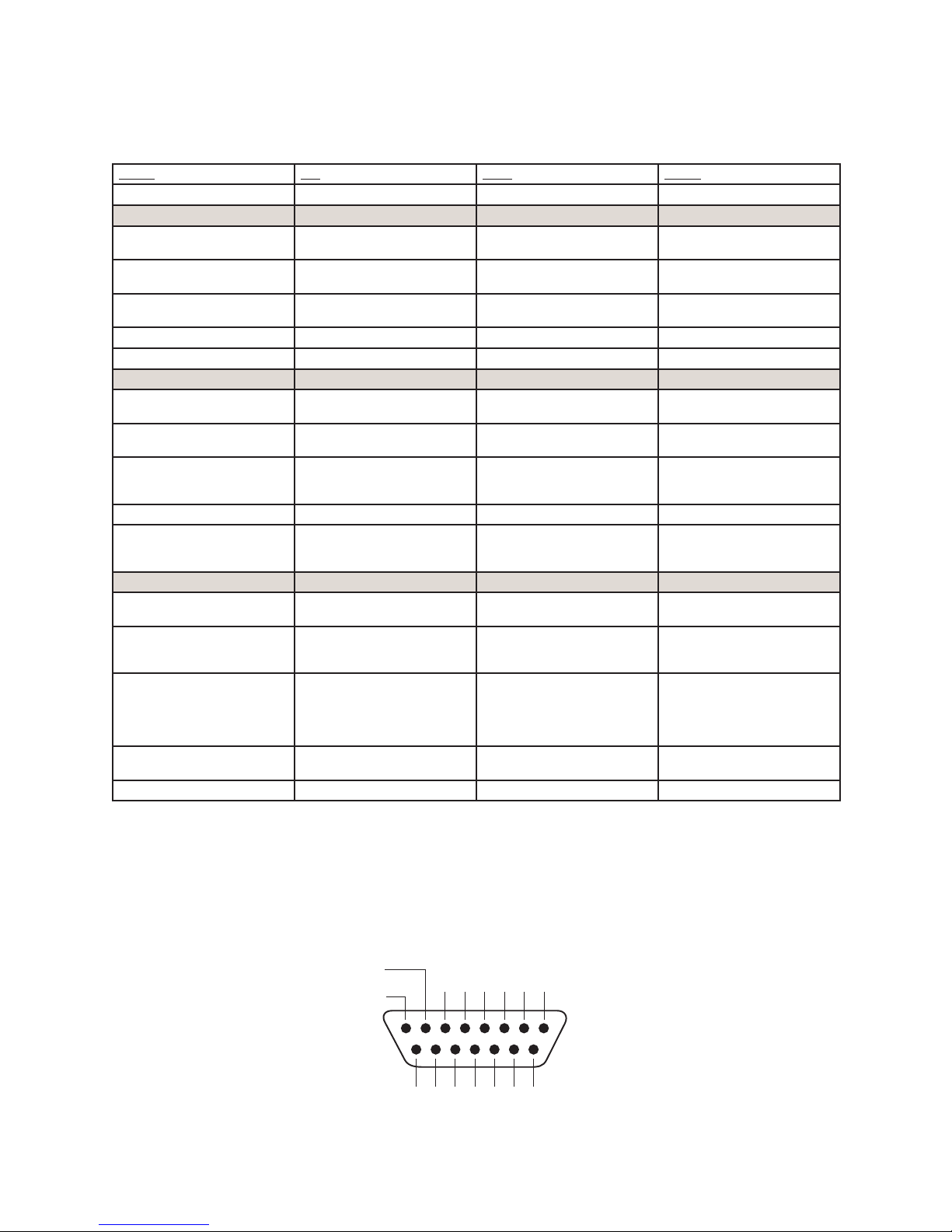
GPIO Studio Monitor Logic
+
SOURCE
Name Pin Type Notes
INPUTS
MUTE Studio Command 11 Active Low Input Allows external muting of
DIM Studio/Monitor 2
12 Active Low Input Allows external dimming of
Command
Remote Event Timer Trigger
13 Active Low Input Resets Count-up Event Timer
Command
NOT CONNECTED 14
Not Used 15 Active Low Input
OUTPUTS
Studio ON A IR Lamp 1 Open Collec tor to Logic Com-
mon Return
DIM Studio/Monitor 2 Lamp 2 Open Collector to Logic Com-
mon Return
Event Timer Trigger Output 3 Open Collector to Logic Com-
mon Return
NOT CONNECTED 4
TALK TO STUDIO/MONITOR 2
Active L amp
5 Open Collector to Logic Com-
mon Return
POWER & COMMON
Source Common 7 Logic Common Connect to ground of source
Logic Common 8 Internal 5 Volt return Can be connected to Pin 7 if
Logic + 5 Volt supply 9 Logic Supply, Individually
Fused
Source Supply 10 Common for all 5 inputs Connect to power supply of
NOT CONNECTED 6
Studio monitor speakers.
Studio monitor speakers.
to zero and star ts timer.
Illuminates whenever Studio
monitors are muted
Illuminates whenever Studio
monitors are DIMMED
A 100 ms PULSE sent when
event timer is star ted from
zero.
Illuminate s whenever the
TALK TO STUDIO/MON2 function is ac tive.
device or to Pin 8
source is not providing common
Can be connected to Pin 10
if source is not providing
voltage; active only when
source has been assigned to
channel.
source device or to Pin 9
5: Conguring GPIO • 48
OUTPUT
COMMON
RETURN
ØV (GND)
SOURCE
OUT
5
8 7 6 5 4 3 2 1
15 14 13 12 11 10 9
IN5IN4IN3IN2IN1IN
OUT
OUT
OUT
OUT
2
3
4
+5 V
POWER
COM
© 2014 Axia Audio - Rev 1.3.1
1N/C
GPIO v.”ZA” 4/2009
Page 57
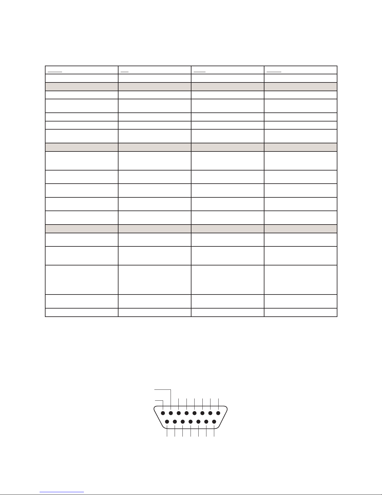
GPIO Computer Playback Device Logic
+
SOURCE
Name Pin Type Notes
INPUTS
ON Command 11 Active Low Input Turns channel ON
OFF Command 12 Active Low Input Turns channel OFF & sends
PREVIEW Command 13 Active Low Input Turns preview ON
Not Used 14 Active Low Input
READY Command 15 Ac tive Low Input Illuminates OFF lamp to indi-
OUTPUTS
NEXT Pulse 1 Open Collector to Logic Com-
mon Return
OFF Lamp 2 Open Collector to Logic Com-
mon Return
PREVIEW Lamp 3 Open Collector to Logic Com-
mon Return
START Pulse 4 Open Collector to Logic Com-
mon Return
STOP Pulse 5 Open Collector to Logic Com-
mon Return
POWER & COMMON
Source Common 7 Logic Common Connect to ground of source
Logic Common 8 Internal 5 Volt return Can be connected to Pin 7 if
Logic + 5 Volt supply 9 Logic Supply, Individually
Fused
Source Supply 10 Common for all 5 inputs Connect to power supply of
NOT CONNECTED 6
100 msec STOP pulse
cate source’s readiness
A 100 mS PULSE sent when
ON button is depressed, except when initially turned ON.
Illuminates when channel is
OFF and READY is ac tive
Illuminates when PREVIEW
is ON
A 100 ms PULSE sent when
channel is rst turned ON.
A 100 ms PULSE sent when
channel is turned OFF.
device or to Pin 8
source is not providing common
Can be connected to Pin 10
if source is not providing
voltage; active only when
source has been assigned to
channel.
source device or to Pin 9
OUTPUT
COMMON
RETURN
ØV (GND)
SOURCE
OUT
5
8 7 6 5 4 3 2 1
15 14 13 12 11 10 9
IN5IN4IN3IN2IN1IN
OUT
OUT
OUT
2
3
4
+5 V
POWER
COM
© 2014 Axia Audio - Rev 1.3.1
OUT
1N/C
GPIO v.”ZA” 4/2009
5: Conguring GPIO • 49
Page 58
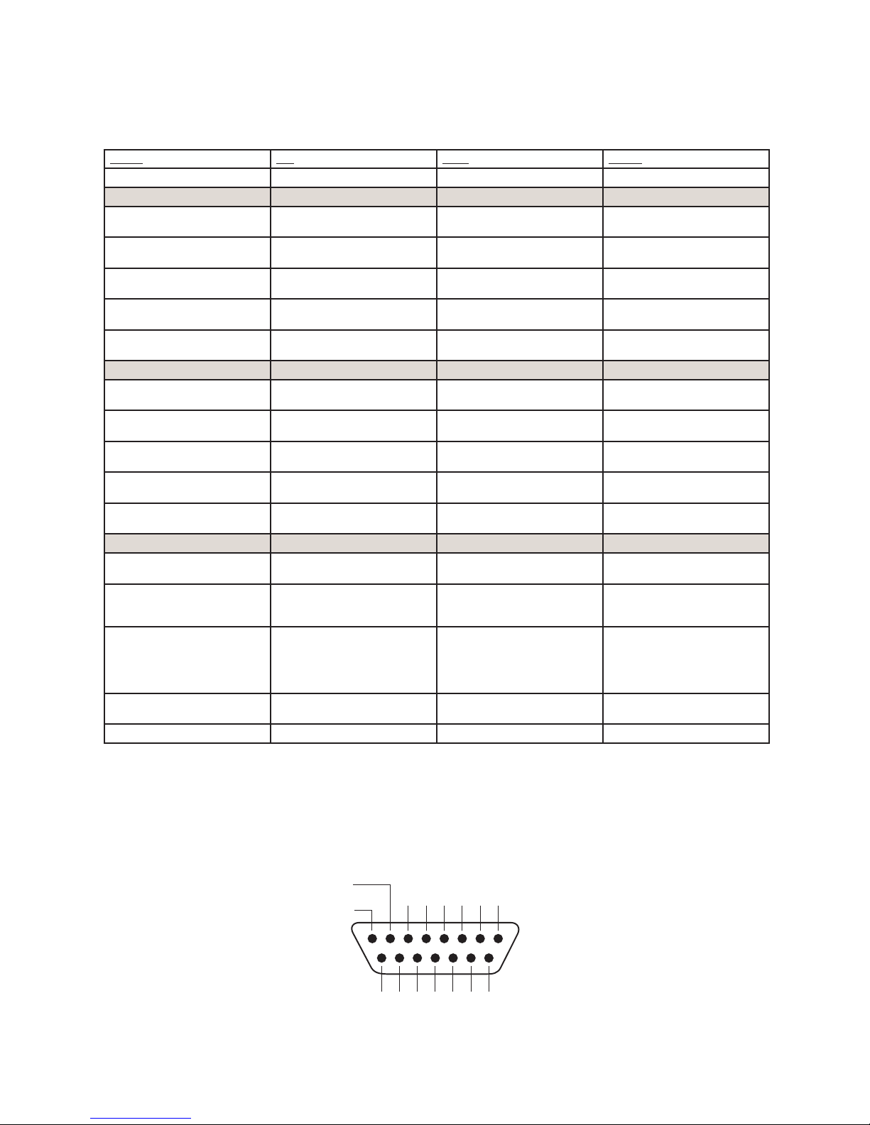
GPIO Film Legendable User Button Module / Accessory Panel / Rack Panel
Name Pin Type Notes
INPUTS
User Button 1 L amp 11 Active Low Input Illuminates User Button 1
User Button 2 L amp 12 Active Low Input Illuminates User Button 2
User Button 3 L amp 13 Active Low Input Illuminates User Button 3
User Button 4 L amp 14 Active Low Input Illuminates User Button 4
User Button 5 L amp 15 Active Low Input Illuminates User Button 5
OUTPUTS
User Button 1 Switch 1 Open Collector to Logic Com-
mon Return
User Button 2 Switch 2 Open Collector to Logic Com-
mon Return
User Button 3 Switch 3 Open Collector to Logic Com-
mon Return
User Button 4 Switch 4 Open Collector to Logic Com-
mon Return
User Button5 Switch 5 Open Collector to Logic Com-
mon Return
POWER & COMMON
Source Common 7 Logic Common Connect to ground of source
Logic Common 8 Internal 5 Volt return Can be connected to Pin 7 if
Logic + 5 Volt supply 9 Logic Supply, Individually
Fused
Source Supply 10 Common for all 5 inputs Connect to power supply of
NOT CONNECTED 6
Lamp
Lamp
Lamp
Lamp
Lamp
Active when User Button 1 is
pushed
Active when User Button 2 is
pushed
Active when User Button 3 is
pushed
Active when User Button 4 is
pushed
Active when User Button 5 is
pushed
device or to Pin 8
source is not providing common
Can be connected to Pin 10
if source is not providing
voltage; active only when
source has been assigned to
channel.
source device or to Pin 9
5: Conguring GPIO • 50
OUTPUT
COMMON
RETURN
ØV (GND)
SOURCE
OUT
5
8 7 6 5 4 3 2 1
15 14 13 12 11 10 9
IN5IN4IN3IN2IN1IN
OUT
OUT
OUT
OUT
2
3
4
+5 V
COM
POWER
+
SOURCE
© 2014 Axia Audio - Rev 1.3.1
1N/C
GPIO v.”ZA” 4/2009
Page 59
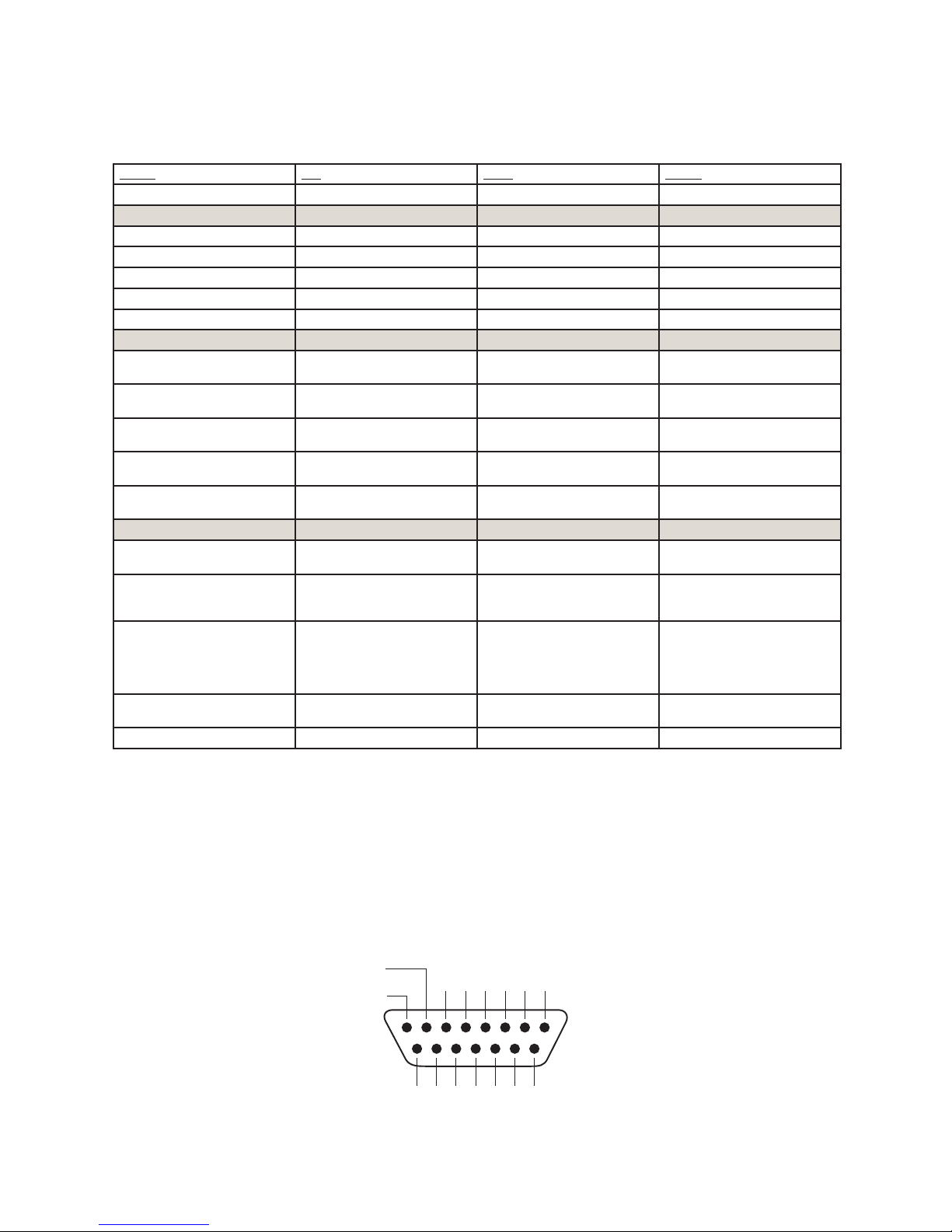
GPIO Recording Device Logic
Name Pin Type Notes
INPUTS
Not Used 11 Active Low Input
Not Used 12 Active Low Input
Not Used 13 Active Low Input
Not Used 14 Active Low Input
Not Used 15 Active Low Input
OUTPUTS
Rec ON Lamp 1 Open Collector to Logic Com-
mon Return
Rec OFF Lamp 2 Open Collector to Logic Com-
mon Return
Not used 3 Open Collector to Logic Com-
mon Return
START Pulse 4 Open Collector to Logic Com-
mon Return
STOP Pulse 5 Open Collector to Logic Com-
mon Return
POWER & COMMON
Source Common 7 Logic Common Connect to ground of source
Logic Common 8 Internal 5 Volt return Can be connected to Pin 7 if
Logic + 5 Volt supply 9 Logic Supply, Individually
Fused
Source Supply 10 Common for all 5 inputs Connect to power supply of
NOT CONNECTED 6
Active whenever Record Mode
is engaged.
Active whenever Record Mode
is NOT engaged.
n/a
A 100 mS PULSE sent when
Record Mode is engaged.
A 100 mS PULSE sent when
Record Mode is disengaged.
device or to Pin 8
source is not providing common
Can be connected to Pin 10
if source is not providing
voltage; active only when
source has been assigned to
channel.
source device or to Pin 9
OUTPUT
COMMON
RETURN
ØV (GND)
SOURCE
OUT
5
8 7 6 5 4 3 2 1
15 14 13 12 11 10 9
IN5IN4IN3IN2IN1IN
OUT
OUT
OUT
2
3
4
+5 V
COM
POWER
+
SOURCE
© 2014 Axia Audio - Rev 1.3.1
OUT
1N/C
GPIO v. 10/2009
5: Conguring GPIO • 51
Page 60
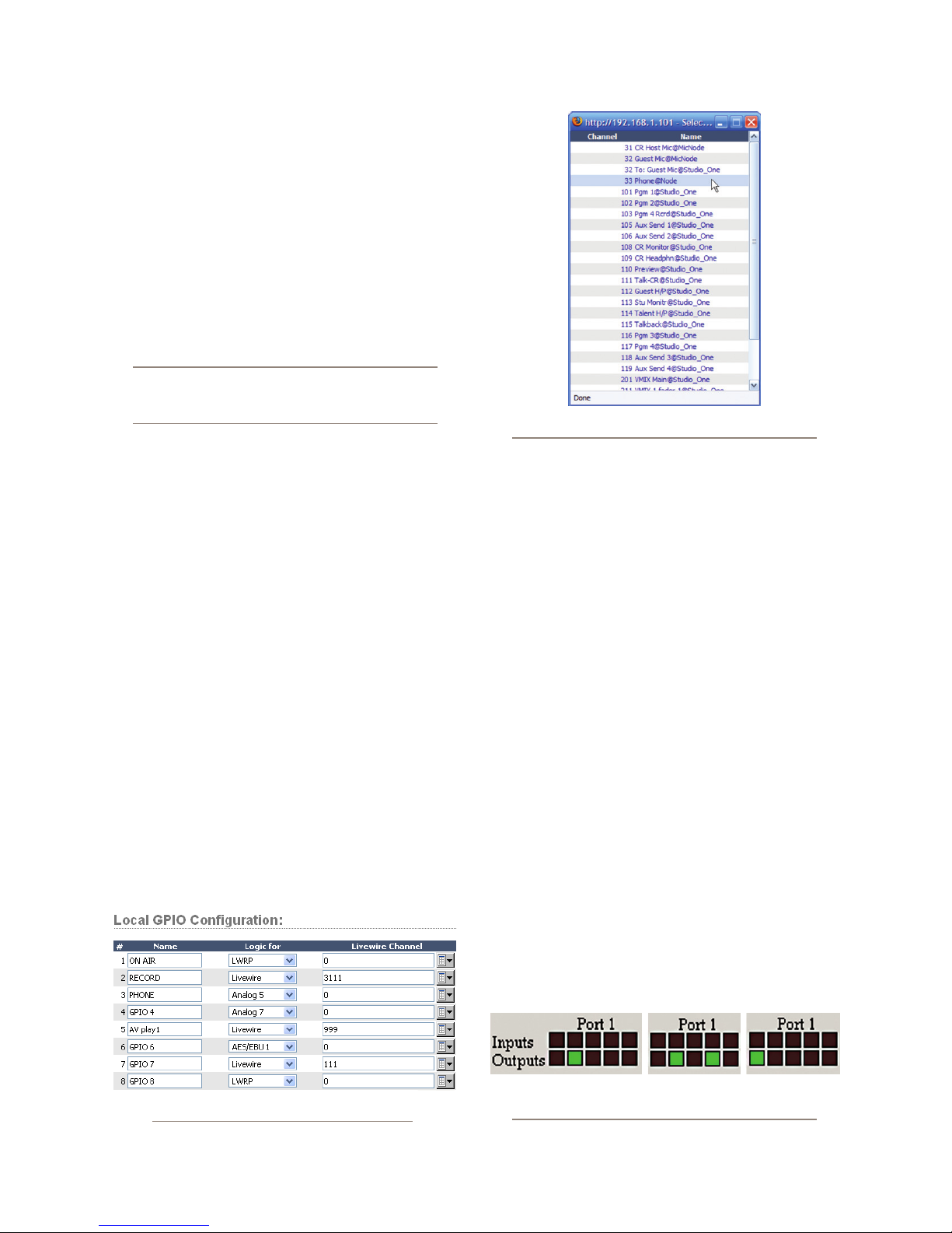
Assigning GPIO to a Source
As you’ve seen by studying the previous pages, a lot
of the work of assigning logic to a source is done for you;
once a GPIO port is linked with a Source Prole, all that
remains to do is to solder cables connecting the GPIO’s
DB-15 connectors to the device’s control interface.
So, how do you link a GPIO port with a Source Pro-
le? It’s very easy; let’s do it step-by-step.
Note: This procedure assumes that you have
already dened at least one Source Prole using
the instructions outlined in Chapter 2.
Figure 5-2: GPIO Select Source popup list
1. Open your Web browser and enter the IP ad-
dress of your console. Choose GPIO Conguration
from menu. Enter your password if prompted (default
login is “user”, leave the password eld blank).
2. If you haven’t previously assigned any GPIO
ports, the GPIO denitions screen will be blank. No-
tice the status indicators at the top of the page, show-
ing the state of the input and output pins of each port.
The “Logic for” option denes how the port will be
used.
» LWRP: The port will only be controlled through
a control protocol. Software packages, as in Path-
nder use the protocol.
» LIVEWIRE: Specify a channel number and the
port will follow the logic associated with that
channel (this will be used for CR monitor logic)
» SPECIFIED INPUT: Dene an input port and
the port will follow the logic of that input.
3. If using the
LIVEWIRE option, you will need
to specify the Channel Number in the Livewire
Channel column. You can do this by manually en-
tering the number, or browsing the network for an
advertised Livewire channel. When you click on
any list icon, a small popup window will open, enu-
merating all of the audio sources available on the
Livewire network (Figure 5-2). Choose the source
you wish to associate with a GPIO port by clicking
on it; the window will close and the source’s name
and channel number will appear in the Channel box.
If you’re using a local source, specify the input. If a
source prole has been created to control a phone
hybrid using Analog 5 as the input, select Analog 5
in the drop down list. The functions of the GPIO port
will now follow those shown in the Hybrid Logic
Chart.
4. Type a descriptive name in the Name eld, and
click on the Apply button.
5. The source we’ve been using for this demon-
stration is a telephone hybrid; we can now observe
the pin status indicators change as we turn the chan-
5: Conguring GPIO • 52
Figure 5-1: GPIO Port Assignment
Figure 5-3: Pin status indicators showing
GPIO por t activity
© 2014 Axia Audio - Rev 1.3.1
Page 61
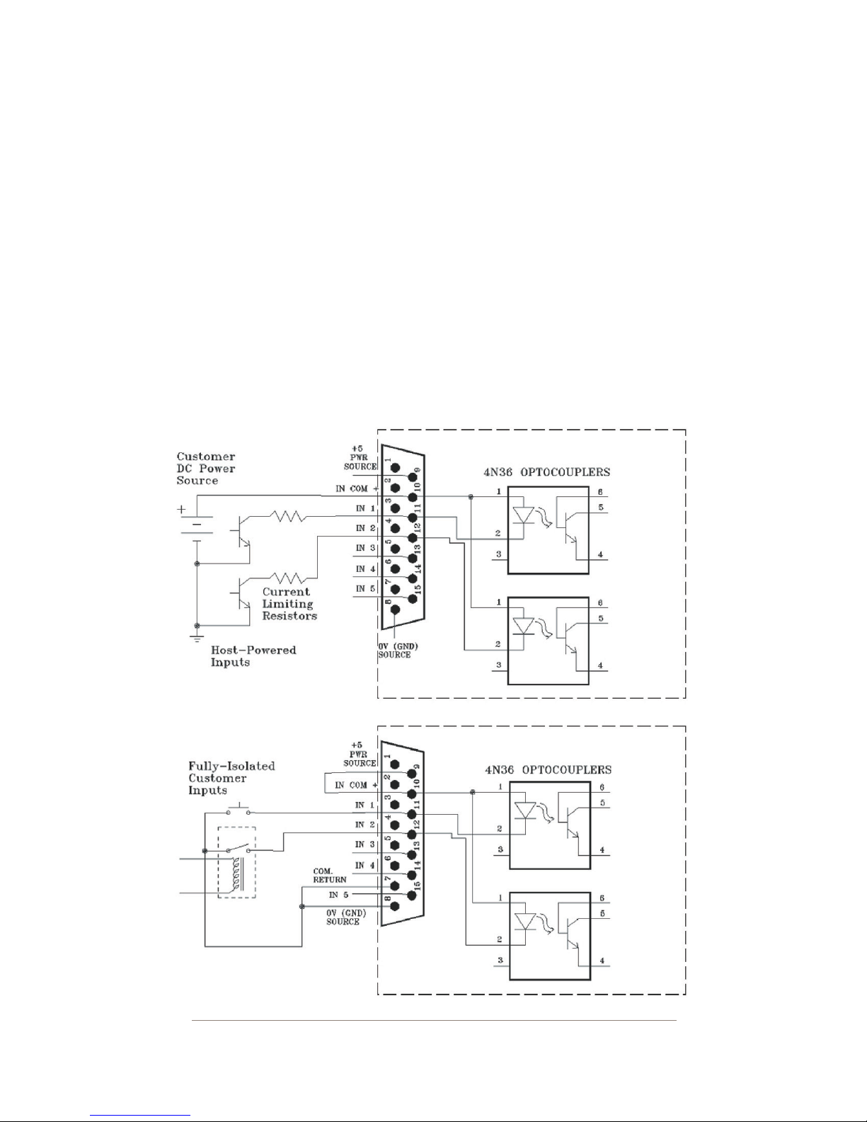
nel on and off, as shown in Figure 5-3.
Referring to the Hybrid Logic Chart, we can see that
when the iQ channel is
ing Output Pin 2 – the Off Lamp logic command – is
high. Turning the channel On, we see Pin 4 pulse
briey before Pin 1 goes high: the GPIO has just sent
a
Start pulse, then lit the On Lamp. If you turn the
channel Off again, you’ll observe a Stop pulse, and
the Off Lamp command once again becomes active.
See how easy that was? Simply assigning an existing
audio source to a GPIO port automagically congures
the port for the type of device supplying the audio, and
send the appropriate logic commands to that port when
Off, the indicator represent-
the source is assigned to a iQ channel.
Connections to GPIO Ports
Input Connections
Current on these inputs must be limited to 20 mA or
less, through the use of a current-limiting resistor. An
external power source (24 volts DC maximum) is rec-
ommended for all inputs and outputs, to prevent ground
loops between equipment. However, if customer equip-
ment is completely isolated, using power from the GPIO
port connectors is acceptable. Figure 5-4 shows details
for both types of connections:
Figure 5-4 GPIO input connections
© 2014 Axia Audio - Rev 1.3.1
5: Conguring GPIO • 53
Page 62
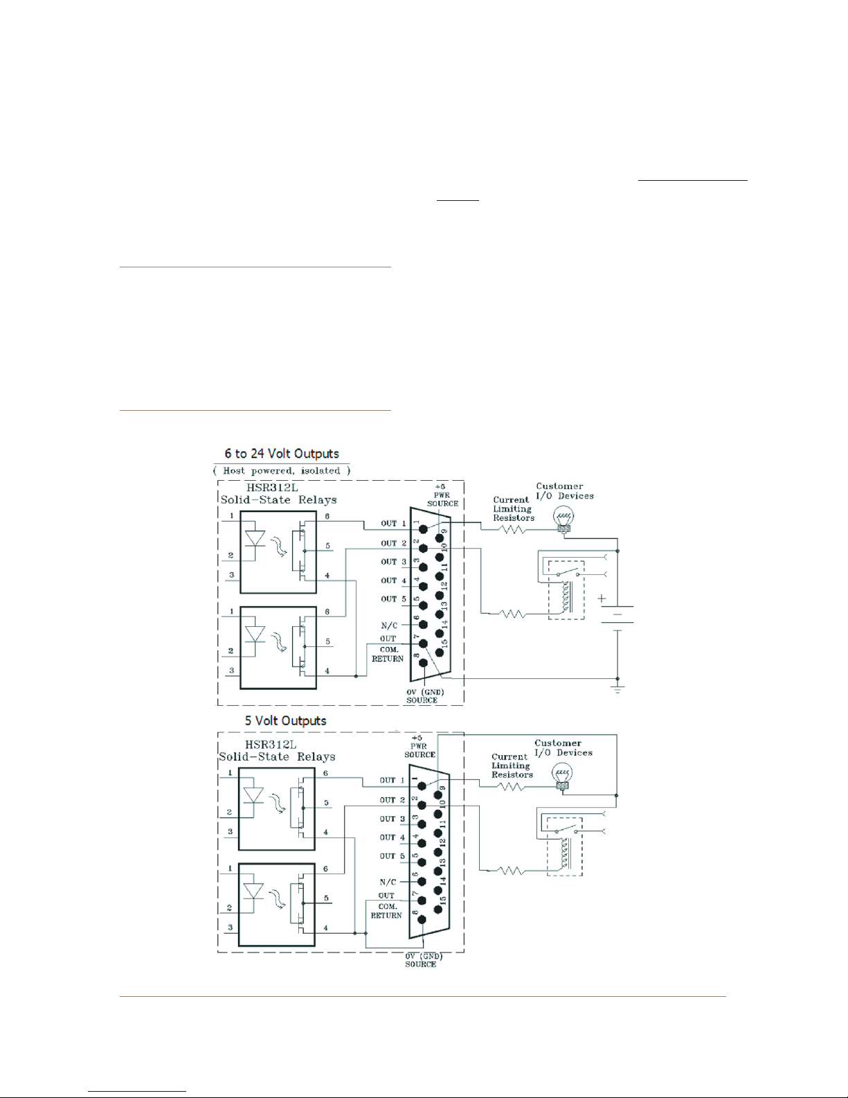
Output Connections
The GPIO port’s outputs are opto-isolated. Current
should be limited 100 mA through each output, with the
total current draw from the +5 Volt supply not to exceed
3 amps. Figure 5-5 shows the recommended connections
for outputs:
NOTE: Some external devices will allow a logic
control input “sink to ground” to activate. Thus,
some devices may not work with an Axia GPO
control, because they may not fully achieve
ground through the output transistor. The voltage drop between the collector and emitter may
not be low enough to activate the device, so an
external relay controlled by the GPO may need
to be used to provide a “dr y” contact closure to
the external device.
Please note that this section is provided as a “jump-
start” introduction to Axia GPIO nodes. For a fuller
understanding of the GPIO node’s options and require-
ments, you may wish to read the GPIO Node User’s
Manual.
Virtual GPIO
Virtual GPIO ports allow you to to avoid having to
wire a GPO pin to a GPI pin in order to achieve a particu-
lar function. The Virtual GPIO ports provide an ability to
dene up to ve GPO pins that can be “virtually wired”
to a single GPI pin. Typically this is used in cases where
you want a GPO function to trigger a different GPI func-
tion. Please refer to the GPIO tables to determine what
those functions are.
5: Conguring GPIO • 54
Figure 5-5: GPIO output connections
© 2014 Axia Audio - Rev 1.3.1
Page 63
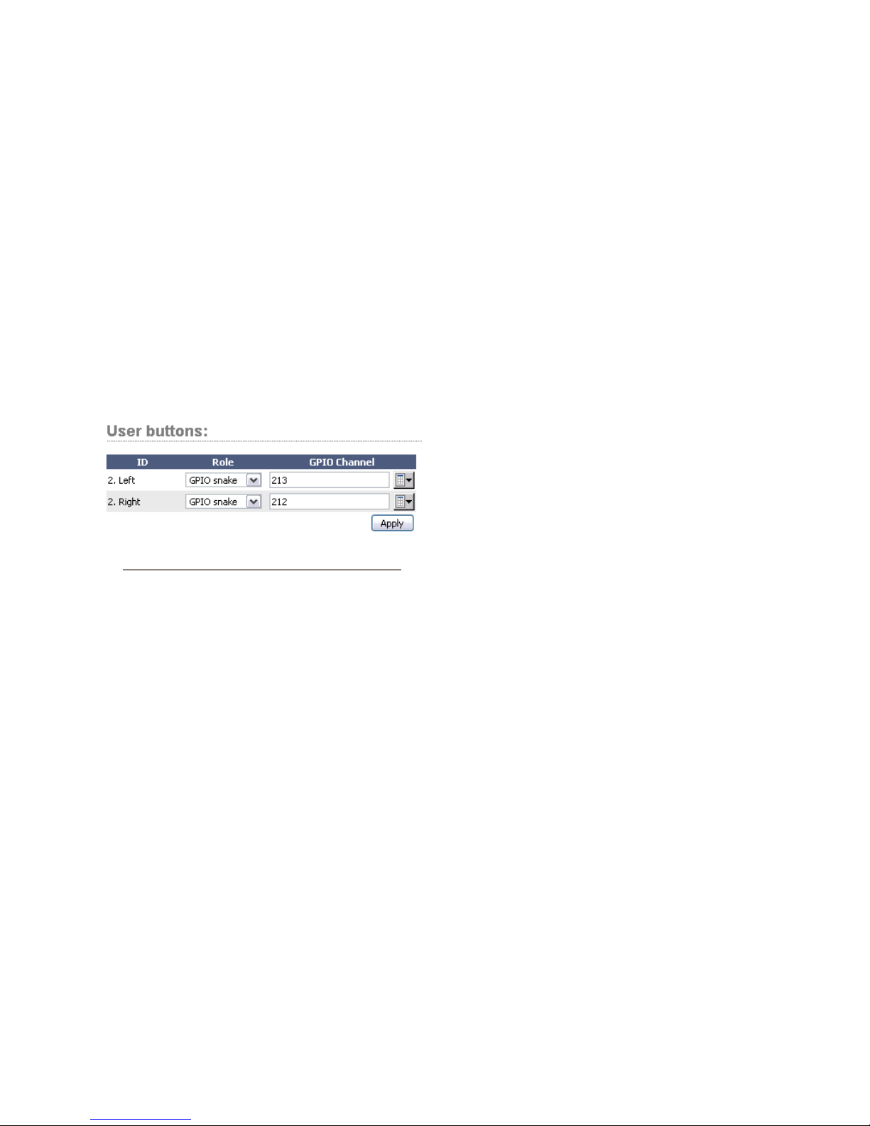
An example of this sort of “virtual GPIO” operation
is triggering the TALK TO EXT command and EXT
PREVIEW command of the CR Monitor logic.
Configuring and using iQ User Keys
The 6 Fader + User Keys iQ expansion module pro-
vides two sets of 5 programmable “user keys.” You’ll
use the iQ Control Center’s Console Conguration page
to congure ports for these keys to use.
When you’ve dened one of the expansion console
units as “Console Ext 6”, you’ll nd a section marked
“User Buttons” that you’ll use to congure the functions
What's Next
When you’re ready, join us in Chapter 6 for a com-
prehensive “under the hood” discussion of iQ Advanced
Controls.
Figure 5-6: User Buttons conguration options
of these keys.
• The ID column identies the User Keys from top to
bottom, and in the left and right columns.
• The GPIO Channel box (and the adjacent selector
boxes) allow you to assign a Livewire GPIO Chan-
nel number to each User Key.
• The Role drop-down selector has two choices:
» GPIO Snake: Choose this option when you want
a button-press to result in a GPO response at the
GPIO port assigned to the GPIO Channel you’ve
specied.
» GPIO module: Choose this option when you
want a button-press to be interpreted as a GPI
command at the GPIO port you’ve assigned
to the GPIO Channel. Also, if the GPIO Chan-
nel has a GPO message issued on the network,
the corresponding button will light, indicating
“ready.”
5: Conguring GPIO • 55
© 2014 Axia Audio - Rev 1.3.1
Page 64

I t r,
ai em
wrke. O, !
5: Conguring GPIO • 56
© 2014 Axia Audio - Rev 1.3.1
Page 65
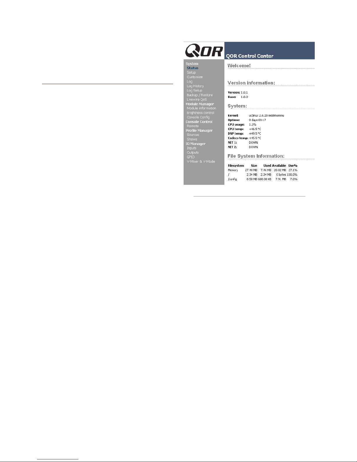
Chapter Six:
Advanced Controls
In previous chapters, we covered the basics of setting
up your iQ. Now that you’re familiar with your console,
you should consider yourself an advanced user! In keep-
ing with your dawning guru status, it’s time for a thor-
ough look at some of iQ’s more advanced conguration
options.
Many of iQ’s features can be customized by soft-
ware settings. And owners like you have given us great
ideas for new operational capabilities, some of which are
included in our periodic software updates. With that in
mind, we strive to keep our documentation as up-to-date
as possible.
If you have questions that are not covered here, we
invite you to contact our 24/7 Support crew:
• by email at [email protected]
• by phone at +1 216-241-7225.
iQ Configuration Screens
The iQ Control Center
Figure 6-1 shows the screen that greets you when
you log into your iQ from your Web browser. The main
menu runs down the left side and gives access to options
and settings. In the main window you can see at a glance
what version of iQ software is loaded, system informa-
tion, CPU statistics, and more. For diagnostic purposes,
this information screen is openly accessible, but clicking
on any menu heading will prompt you for a password.
Here you’ll nd options related to the QOR.32, iO Fader
Frames and Ethernet switch.
The Status Screen
The Status screen is your home page. It displays ba-
sic system status as well as information pertaining to the
active software load. A sample of this screen is shown
in gure 6-1. Additional information displayed may in-
Figure 6-1: Status Screen
clude::
• iQ software version info including the current active
Version and Base
• System Information including:
» Version of Linux kernel
» Uptime of the iQ expressed in days, hours and
minutes
» CPU utilization
» Network Information
» Network status and utilization - transmit and re-
ceive data rates expressed in Mbps.
» Debug information
• File System Information - provides information on
memory and solid state disk utilization for the oper-
ating system. This information may be requested by
Axia tech support.
The Setup Menu
We touched briey on the IP features of the Setup
screen in Chapters 1 and 2. Now let’s look at the rest of
the tools on this page shown in Figure 6-2.
• Network Conguration contains the elds for the
iQ IP Address and other network functions.
» Hostname is the unique name you give the con-
sole to identify it in the Web interface. You might
want to name it after the studio it’s in.
6: Advanced Controls • 57
© 2014 Axia Audio - Rev 1.3.1
Page 66
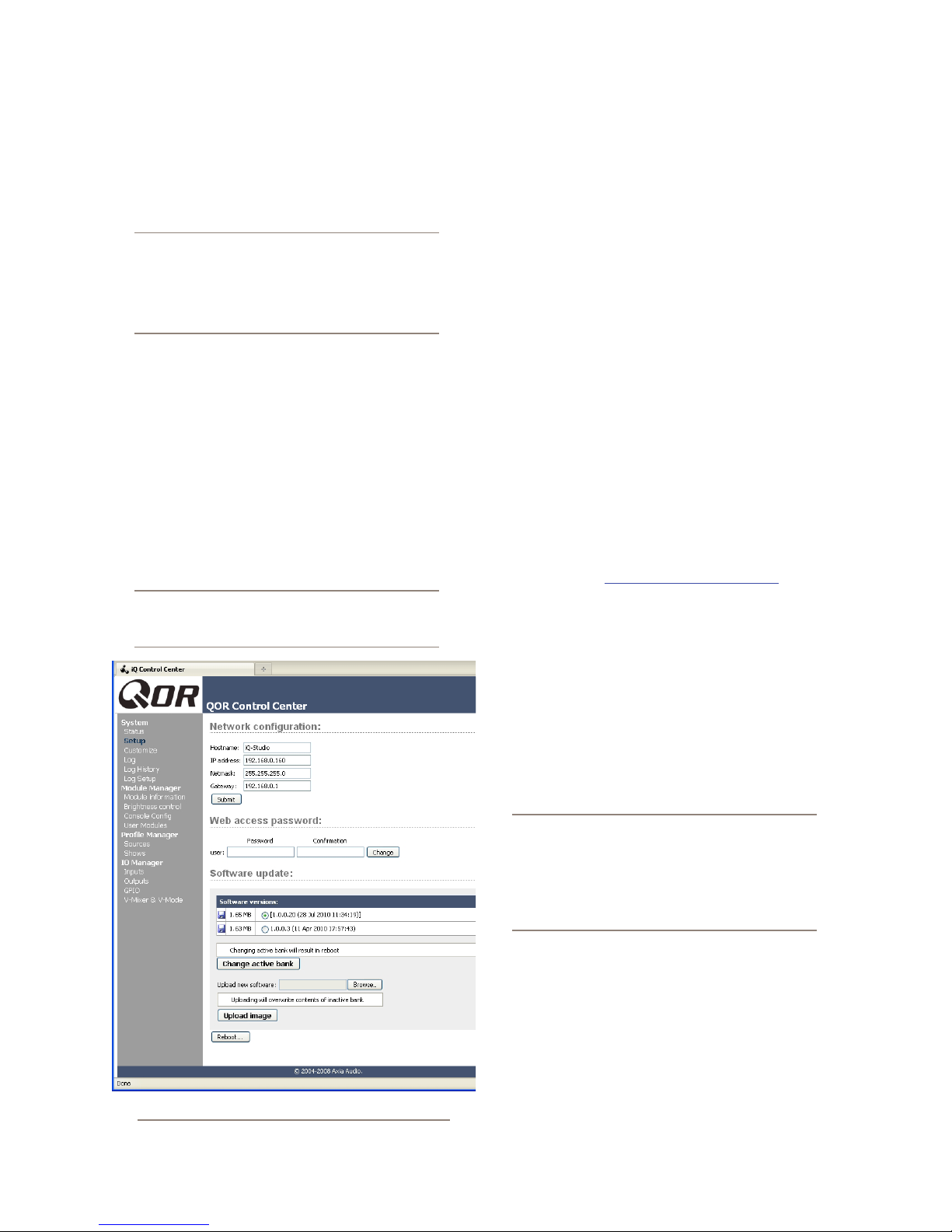
» IP Address: This is the network address of your
iQ. We suggest that you have a plan to ensure that
all of your Livewire devices are assigned unique,
IP addresses.
Shortcut Key: You can also set the IP address
of your iQ by simultaneously pressing and holding the Meter and Clock keys on the iQ Console. Use the Studio Monitor knob to navigate
and follow the prompts to give your iQ a new IP
address.
» Netmask: Enter your network’s submask here.
If you are not sure about this - consult your net-
work administrator. In most cases a Netmask of
255.255.255.0 is suitable.
»
Gateway: If you have a Core switch or a net-
work gateway to allow access from outside your
facility, enter that address here. A gateway is re-
quired for advanced IP address congurations
and for connection to an external NTP server.
Note: A reboot is required when any changes
are made to the network parameters on the iQ
Setup Menu.
• Web Access Password: By default, the user name
is set to “user” and the password is blank. If you
want to add a password, type it in both boxes and
click
Change. Note that passwords will not display
here once changed, so be sure to make a record of all
password changes.
•
Software Update: This is where you upload new
iQ operating software.
» Software Versions shows you the software
packages currently stored on your iQ ash mem-
ory card. The blue radio button is displayed next
to the active software image.
»
Change Active Bank: When you want to
change the active software package, click on the
radio button next to the image you wish to acti-
vate, and click this button. A reboot is necessary
to load the new software choice.
»
Upload Image: From time to time, Axia makes
new software packages available for down-
load from AxiaAudio.com/downloads/. Use the
Browse and Upload Image buttons to install
new software, as described in the Technical Bul-
letin that accompanies each software release.
Note that uploading a new image will always
over-write the inactive bank.
» Reboot shuts down iQ and restarts it. A reboot
is required after changing active software or after
changing any settings in your Network Congu-
ration.
6: Advanced Controls • 58
Figure 6-2: Setup Screen
Save your work! We recommend backing
up your Conguration les whenever a major
change is made, or is about to be made, to your
iQ. Whether you are re-conguring Show or
Source proles en masse or about to perform a
software update, it’s always a good idea to have
a copy of your important data.
The Customize Menu
The Customize page contains Clock settings and
Backup/Restore functions. Future enhancements may
include additional features in this area.
• Clock Options
» Clock Format: This is where you dene whether
you will view your time in 12 hour or 24 hour format.
© 2014 Axia Audio - Rev 1.3.1
Page 67
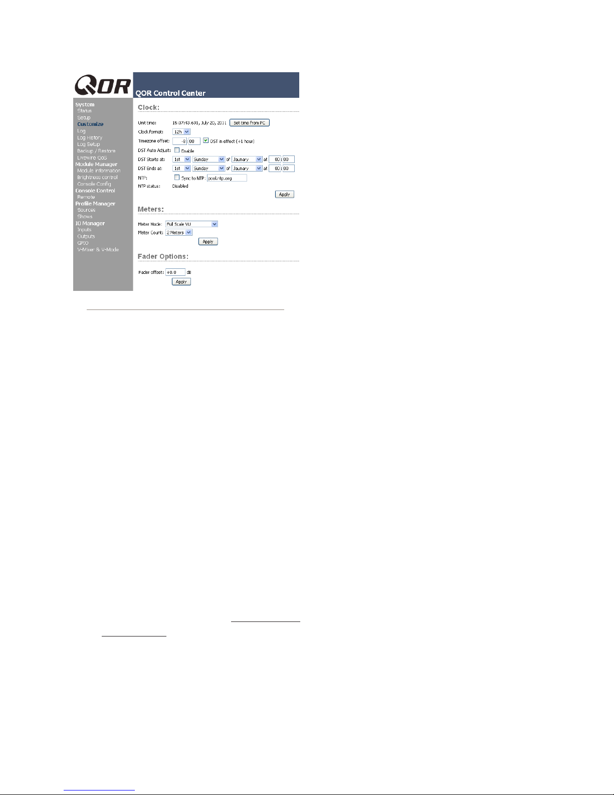
Figure 6-3: Customize Sc reen
Each individual IQ in your network can use either
its own internal clock or an external time server
for timekeeping. The next group of settings will
set up NTP (Network Time Protocol) time sync.
» Time Zone Offset: Specify your local GMT
offset in hours and minutes. For example, if you
live in the Eastern Tome zone in the USA, your
GMT offset will be -5 hours, 0 minutes. If you
live in Riga, Latvia, your offset will be +2 hours.
» DST in effect (+1 hour): In those area that im-
plement Daylight Savings Time, this check box
is used to tell your system to add one hour to the
GMT offset.
» NTP: The check box should be checked if your
iQ’s NTP clock sync function is enabled. To
disable NTP service, simply un-check this
box. The other box here is used to enter the
IP address of your external NTP server. This
server may be a PC on your local network or
it may be the IP address of a public NTP serv-
er in the Internet. Note that you must speci-
fy an IP address – a URL will not work.
If you wish to connect to a public or external
NTP server, be sure to specify a valid Gate-
way in your IP conguration.
You can tell if your NTP connection is working
by observing the presence of the NTP indicator
next to the clock display on your iQ overbridge.
•
Connguration: This is an extremely important
area of your iQ conguration since this is where you
will backup all of the hard work you have done.
» Backup Settings: All iQ settings can be
saved in a single operation and backed up to a
location on your local drive. When you select
the
Backup option, you will see the famil-
iar location navigator that prompts you for the
folder in which you wish to store your backup
le. The backup le will be named according
to the device name, IP address and date/time
the backup was performed. This naming con-
ventions allows you to store multiple backups
from multiple devices in the same location. An
example of an IQ backup’s le name might be
IQ-192.168. 0.20 0 -2010 - 03-25_17-13.xml.
»
Restore Settings: To restore a previous iQ
backup, use the browse button to locate the back-
up and then select Restore.
Log, Log History and Log Setup Menus
iQ keeps a detailed log of user actions and other sys-
tem events. Choosing the Log menu item lets you ex-
amine the last 100 logged activities; choosing the Log
History menu item allows you to view an entire day’s
log at one time and delete old log les if you choose.
The oldest log les are deleted automatically as storage
space dictates.
The Log Setup menu item allows you to specify an
external Syslog server and to congure the debug level.
This menu also allows you to specify from eight differ-
ent severity level lters. The lter choices (in order of
decreasing severity) are:
• Emergency: system us unusable
• Alert: action must be taken immediately
• Critical: critical condition
• Error: error conditions
• Warning: warning conditions
• Notice: normal but signicant condition
• Informational: informational messages
• Debug: debug level messages
6: Advanced Controls • 59
© 2014 Axia Audio - Rev 1.3.1
Page 68
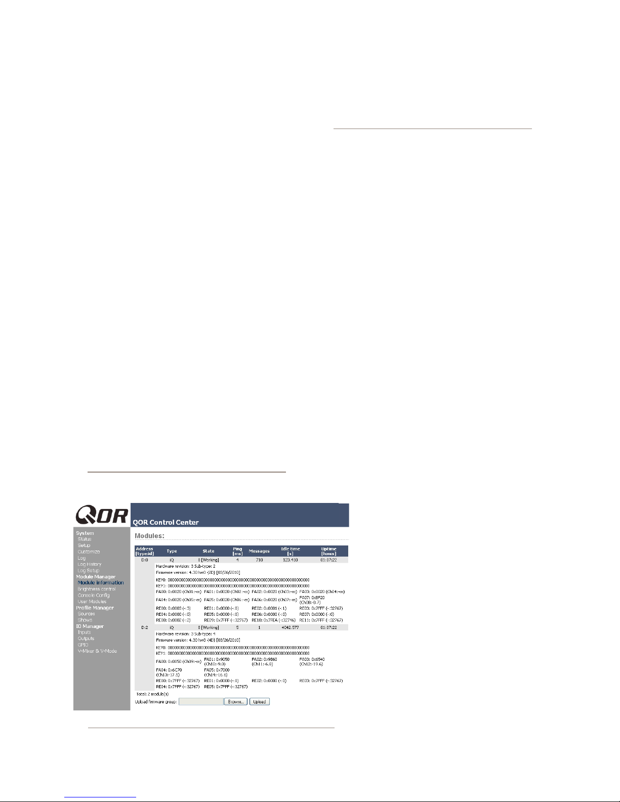
Use this section as directed to do so by Tech Support.
The Module Manager
The
Module Manager heading displays information
about the iQ Main Frame as well as all other modules
(fader frames) and accessories connected to your CAN-
Bus ports. Some of these elds are for diagnostics; below
is a list of those you might nd useful:
»
Address: displays the number Axia has assigned
to each connected unit.
»
Typ e : gives you the working name of the module.
» State: tells you whether or not the module is
working, i.e., communicating with the Core CPU.
» Ping: Indicated ping response in ms.
»
Messages, Idle Time, Uptime: All indicate di-
agnostic information that is related to the CAN-
Bus communications. Tech support may request
this information for troubleshooting purposes.
» Hardware Revision: displays the hardware ver-
sion of the iQ module.
» Firmware Version: displays the rmware ver-
sion that’s loaded on the iQ module.
» Upload Firmware Group: From time to time,
new module rmware may become available
from Axia. You may install new rmware by
choosing Browse and then Upload.
NOTE: Updating a module takes it ofine during
the update process. While audio playing through
the module’s faders will continue uninterrupted,
keep in mind that while updating (usually about
10-15 seconds) you will not be able to adjust
gain or turn faders on or off on the module being updated.
Brightness Control Menu
This menu offers several options for ne-tuning your
iQ displays to your studio’s ambient lighting. All val-
ues are expressed in percent. The default setting will be
suitable for most studio environments, however you may
make adjustments as needed.
User Modules Menu
This menu allows you to set up and use Axia acces-
sory SmartSwitch and Film-Cap Button modules and
accessory panels with your console. This area is where
you will nd settings for the 10 User Keys found on
the 6-fader Frame. Axia PathnderPC software is used
to provide powerful logic functions controlled by these
keys.
GPIO Conguration Menu
This menu is where you congure the assignments
for the four opto-isolated GPIO connections found on
the rear panel of the QOR.32. For a thorough discussion
of this screen and how to congure GPIO, please refer to
Chapter 5: Conguring GPIO.
Remote
The remote function available through the
web interface gives you many of the same con-
trols that are on the surface:
• You have the option to load a Show prole
by selecting the show in the dropdown se-
lector, and then pressing the
Load button.
• You can activate the Record mode.
• Each fader channel is shown with an op-
tion to change the source, change the ON
state, assignments to the four mixes, and
Preview state.
6: Advanced Controls • 60
Figure 6-4: Modules Manager
In order to change a state, you must make
the selection to the channel and press the Ap-
ply button for that row. This is control of a sin-
gle channel at a time. Below the Fader Chan-
© 2014 Axia Audio - Rev 1.3.1
Page 69
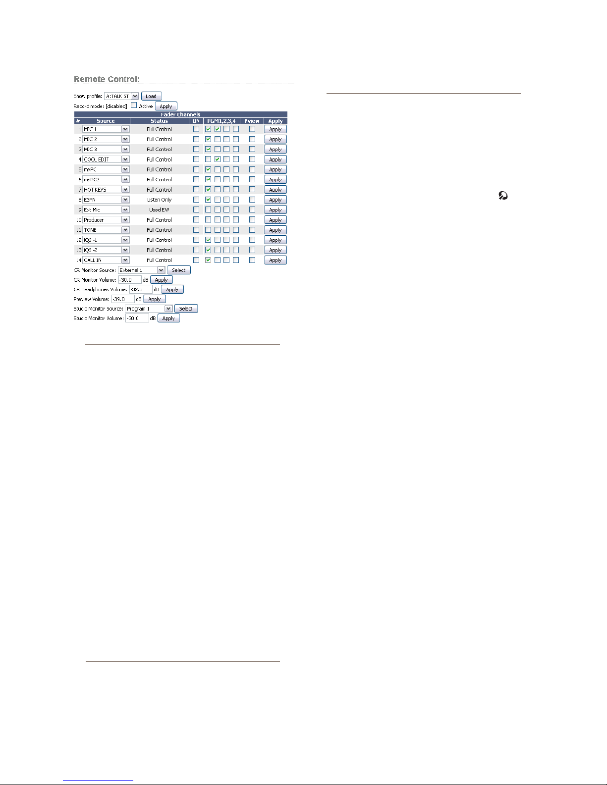
Figure 6-5: Remote Screen
tact [email protected] for explanations of
any differences you may nd.
What’s Next
iQ is designed to be the perfect standalone IP con-
sole. But what if you want to use your iQ as part of a
larger Livewire studio network? No problem! Read on as
we congure networking options for your iQ.
nels section are the controls for the monitors, where the
source and volumes for a monitor can be adjusted.
Prole Manager Menu
These menus allow you to construct and administer
Show and Source Proles specic to this iQ console. Re-
fer to Chapter 2: Inputs and Outputs and Chapter 4:
Show Proles for details on Source and Show proles.
IO Manager Menu
These menus allow you to administer your iQ’s au-
dio Inputs and Outputs. Refer to Chapter 2: Inputs and
Outputs for complete details on conguration of these
controls.
Ethernet Switch settings (Precongured)
QOR.32 contains an integrated Ethernet switch. This
switch manages the multicast functions of the console
and enables it to be connected to other devices via your
managed Livewire LAN.
NOTE: We make every effort to keep our manuals up-to-date, but sometimes R& D works
quicker than our documentation elves! Controls
documented in this section may vary from those
actually presented on your product. Please con-
6: Advanced Controls • 61
© 2014 Axia Audio - Rev 1.3.1
Page 70

Dr, dr s co tr
rs , r n rng.
’s Strucs r .
6: Advanced Controls • 62
© 2014 Axia Audio - Rev 1.3.1
Page 71
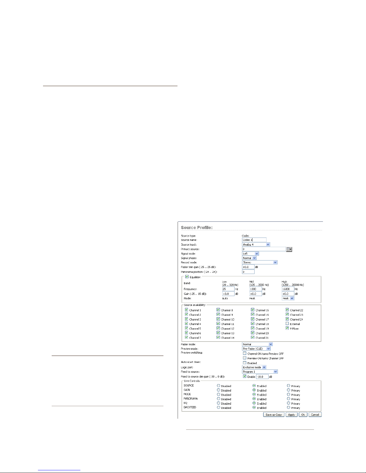
Inputs
Chapter Seven:
Networking with iQ
iQ is a superb standalone broadcast console — but
that’s just half the story! Like all Axia broadcast prod-
ucts, iQ has networking capabilities as well.
Axia invented networked audio for broadcast. We
call it Livewire, and iQ uses this networking ability in
several different ways:
• Your iQ console can load and utilize sources
from other studios connected to your Livewire
network.
• You may deliver outputs from your iQ to the
Livewire network for use by others.
• Naturally, iQ can also use GPIO logic that is
available on your Livewire network.
• The Livewire network allows you to use our
companion software package, PathnderPC,
for numerous advanced functions. The list of
features provided by PathnderPC is growing
continuously.
• Up to four iQ consoles can be congured dai-
sy-chain style, without the need for an exter-
nal core Ethernet switch, to take advantage of
network redundancy provided by implemen-
tation of the Spanning Tree Protocol (STP)
standard.
• You can manage your iQ remotely using its
web browser interface.
• Conguration backup and restore operations
may be performed over the network as well.
Congratulations — your iQ console is the world’s
rst broadcast mixer with a custom, built-for-broadcast
Ethernet switch built right in!
When properly congured and connected to other
iQ consoles (or, in a large studio facility, to an Ethernet
“core” switch), this network connection permits you to
access the resources of other devices connected to your
network.
iQ has a “gateway” for exchanging audio data with
the rest of your Livewire network, with two modes of
operation.
In the rst mode, iQ can consume up to 12 Livewire
audio streams from the network, and it can deliver 4
Livewire audio streams to the network.
For an in-depth discussion of Livewire, please
review our publication “Introduction to
Livewire: IP-Audio System Design Reference and Primer,” which provides an excellent
discussion of IP-Audio and how standard Ethernet can be used to transport real-time broadcast audio in a studio environment. This publication is available at AxiaAudio.com/manuals/.
© 2014 Axia Audio - Rev 1.3.1
Figure 7-1: Codec Source
Chapter 7: Networking with iQ • 63
Page 72
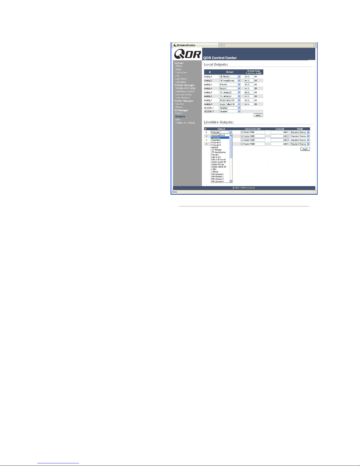
Chapter 7: Networking with iQ • 64
In the second mode, iQ can consume up to 8
Livewire audio streams from the network, and it can
deliver 8 Livewire audio streams to the network.
To understand this, it might help to envision this
network connection as a high-speed freeway, with 8
or 12 “lanes” coming towards your studio, and 8, or
4, lanes going away from your studio, to the network.
To select the mode you wish to operate in, point
your browser to the “Customize” page in the QOR
Control Center, and use the “Livewire Mode” option
to select either “8 in, 8 out” or “12 in, 4 out.”
Selecting the Source Input
In Chapter 2: iQ Inputs and Outputs, we dis-
cussed the iQ console’s local inputs - those associ-
ated with the XLR and RJ-45 connectors on the rear
panel of the QOR.32. We saw how we could associ-
ate each of these physical inputs with a Source Pro-
le. The type of source (CR mic, Guest mic, codec,
phone, etc) determined parameters such as monitor mut-
ing and backfeeds.
When each Source Prole is congured, you have a
choice for the Source Input. If you select one of the rear
panel connectors, the console source is associated with
that input. If you select Livewire, you are telling the iQ
that this source is not associated with a local input but is,
instead, a source from elsewhere on your Livewire net-
work. You may then assign that Primary Source by us-
ing the Browse button to choose from a list of Livewire
sources. That’s all there is to it!
Figure 7-1 shows an example of a codec source
that’s been congured as a Livewire Source Input with a
network Primary Source. In this example, the Livewire
Channel Number of that source is 1037 and it is com-
ing from an Axia node named AES-103. The source has
a designation of CODEC_1 on that node. Everything
else in the conguration of the Source Prole is exactly
the same as if that codec was connected directly to the
QOR.32.
In summary, your iQ console sources inputs may be
Figure 7-2: Livewire Outputs
congured from any of the rear panel connectors (4 x
microphone, 16 stereo analog, 2 x AES) or from as many
as 12 incoming Livewire network sources for a total of
up to 34 sources. These network sources may be rede-
ned at any time, facilitating a highly exible system!
Outputs
The Output conguration of your iQ has two sec-
tions: one for Local Outputs (rear panel connectors)
and one for Livewire Outputs. As you might expect, the
Local Outputs are usually congured for feeds to in-stu-
dio devices like CR Monitors, headphone ampliers, etc.
The Livewire Outputs consist of four streams from
your iQ that you wish to deliver to your Livewire net-
work. These four streams will be available to other de-
vices and users on your network.
The following parameters are congured for each of
the four Livewire Outputs:
• Output: Species the audio feed to be delivered to
the network on each of the four Livewire channels.
Selections include:
© 2014 Axia Audio - Rev 1.3.1
Page 73
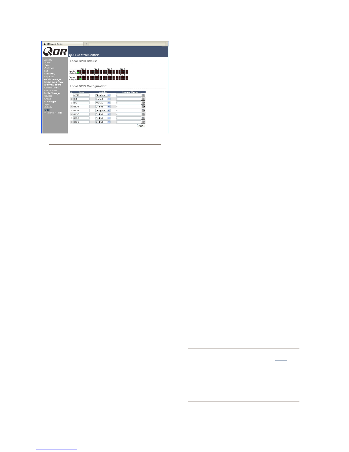
Figure 7-3: GPIO
» Any of the local inputs: 4 microphone, 16 stereo
line or 2 digital AES inputs.
» Any internal generated iQ sources including
PGM-1, 2, 3 or 4, Record, CR Monitor, CR
Headphones, Preview, Talk to CR, Talk to Ex-
ternal, Studio Guest HP, Studio Monitor, Stu-
dio Talent HP, and Auto Backfeed.
» VMix or VMode outputs.
• Name Override: Allows you to specify a name
(16 characters maximum) that will describe this iQ
source to network users. This eld will override the
source name specied in the local Source Prole.
• Channel: The Livewire channel designation. Spec-
ify a unique channel number between 1 and 32,767
that will be used by the Livewire network to identify
your iQ’s network audio.
• Mode: Enables and chooses the stream priority for
this channel. Options are:
» Disabled - the channel is off.
» Live Stereo - Choose this when the audio output
contains live voices or other high-priority audio.
» Standard Stereo - Choose when the audio out-
put consists of pre-recorded music or program-
ming.
GPIO
The QOR.32 has eight physical GPIO ports present-
ed on DB-15 connectors. Often, these ports are associat-
ed with local sources for logic control of devices such as
CD players or for external on/off control of your micro-
phones. In these cases, select the local source to which
you wish to map the GPIO port by using the Logic For
drop down box.
Sometimes, however, you may wish to use GPIO
logic that is associated with some other Livewire net-
work audio source. In this case, you will select Livewire
from the Logic For drop-down. You may then enter
the Livewire channel number directly or by using the
Livewire button on the right side of the screen. When
you click on this button, a pop-up prompts you to select a
Livewire channel from your network; the GPIO port will
then become the logic interface for that Livewire source.
Networking
To deploy iQ in a network setting, you will intercon-
nect the Ethernet switch built into your QOR.32 with
other QOR.32s, or to external Ethernet switches.
The QOR has a zero-conguration, built-for-broad-
cast network switch. It does not require any congura-
tion in order to connect it with other Livewire studios.
If you’re connecting it to another QOR in “daisy-chain”
mode, simply use CAT-6 Ethernet cable to connect one
of the Gigabit ports to a Gigabit port on the other QOR.
If you’re connecting it to a larger network’s core switch,
connect one of the Gigabit QOR ports to a properly con-
gured and approved Core switch.
As a point of clarication, the QOR’s Ethernet switch
differs from an off-the-shelf network “core” switch in
the following ways: The Ethernet switch in a QOR.32 is
always at the “edge” of a large Livewire network. In IT
parlance, this type of switch is actually referred to as an
“edge” switch.
IT Note: If your system employs an Ethernet
core switch, the Ethernet core switch must have
an IP address numerically lower than any of
your iQ units or Ethernet edge switches. This
function of the IGMP standard ensures that the
multicast querier is handled by the core switch
if one exists. The querier function will be passed
off transparently to another switch should the
core switch fail or be disconnected.
Chapter 7: Networking with iQ • 65
© 2014 Axia Audio - Rev 1.3.1
Page 74

Mcng r,
res cn t r n
ny m n.
Chapter 7: Networking with iQ • 66
© 2014 Axia Audio - Rev 1.3.1
Page 75

Appendix A:
iQ Specifications
Microphone Preampliers
Source Impedance: 150 ohms
Input Impedance: 4 k ohms minimum, balanced
Nominal Level Range: Adjustable, -75 dBu to -20 dBu
Input Headroom: >20 dB above nominal input
Output Level: +4 dBu, nominal
Analog Line Inputs
Input Impedance: 20 k Ohms
Nominal Level Range: Selectable, +4 dBu or -10dBv
Input Headroom: 20 dB above nominal input
Analog Line Outputs
Output Source Impedance: <50 ohms balanced
Output Load Impedance: 600 ohms, minimum
Nominal Output Level: +4 dBu
Maximum Output Level: +24 dBu
Digital Audio Inputs and Outputs
Reference Level: +4 dBu (-20 dB FSD)
Impedance: 110 Ohm, balanced (XLR)
Signal For mat: AES-3 (AES/EBU)
AES-3 Input Compliance: 24-bit with selectable sample
rate conversion, 20 kHz to 216kHz input sample rate
capable.
AES-3 Output Compliance: 24-bit
Digital Reference: Internal (network timebase) or external
reference 48 kHz, +/- 2 ppm
Internal Sampling Rate: 48 kHz
Output Sample Rate: 48 kHz
A/D Conversions: 24-bit, Delta-Sigma, 256x oversampling
D/A Conversions: 24-bit, Delta-Sigma, 256x oversampling
Latency <3 ms, mic in to monitor out, including network
and processor loop
Crosstalk Isolation, Stereo Separation and CMRR
Analog Line channel to channel isolation: 90 dB isolation
minimum, 20 Hz to 20 kHz
Microphone channel to channel isolation: 80 dB isolation
minimum, 20 Hz to 20 kHz
Analog Line Ster eo separation: 85 dB isolation minimum,
20Hz to 20 kHz
Analog Line Input CMRR: >50 dB, 20 Hz to 20 kHz
Microphone Input CMRR: >50 dB, 20 Hz to 20 kHz
Audio Processing
Mic Equalizer (applicable to up to 6 faders)
Frequency Bands: 20Hz to 320Hz, 125Hz to 2KHz, 1.25KHz
to 20KHz.
Cut/Boost range on each band: -25dB to +15dB.
Q-factor: Automatic - bandwidth varies based on amount of
cut or boost.
Power Supply AC Input, QOR.32 with iQ Console
Auto-sensing supply, 90VAC to 240VAC, 50 Hz to 60 Hz,
IEC receptacle, internal fuse
Power consumption: 100 Watts
Operating Temperatures
-10 degrees C to +40 degrees C, <90% humidity, no con-
densation
Dimensions (HxWxD) and Weight
QOR.32: 7 x 19 x 15 inches (4RU), 15 pounds
See the gures that follow for detailed dimensions of iQ
frames.
Frequency Response
Any input to any output: +0.5 / -0.5 dB, 20 Hz to 20 kHz
Dynamic Range
Analog Input to Analog Output: 102 dB referenced to 0
dBFS, 105 dB “A” weighted to 0 dBFS
Analog Input to Digital Output: 105 dB referenced to 0
dBFS
Digital Input to Analog Output: 103 dB referenced to 0
dBFS, 106 dB “A” weighted
Digital Input to Digital Output: 125 dB
Equivalent Input Noise
Microphone Pr eamp: -128 dBu, 150 ohm source, reference
-50 dBu input level
Total Harmonic Distortion + Noise
Mic Pre Input to Analog Line Output: <0.005%, 1 kHz, -38
dBu input, +18 dBu output
Analog Input to Analog Output: <0.008%, 1 kHz, +18 dBu
input, +18 dBu output
Digital Input to Digital Output: <0.0003%, 1 kHz, -20 dBFS
Digital Input to Analog Output: <0.005%, 1 kHz, -6 dBFS
input, +18 dBu output
© 2014 Axia Audio - Rev 1.3.1
Appendix A: Specications • 67
Page 76

Table of Inputs and Outputs
Main Outputs Type Comments
Program 1 Stereo Main stereo bus (Usually referred to as Program)
Program 2 Stereo Second stereo bus (Sometimes referred to as Audition)
Program 3 Stereo Third stereo bus (Sometimes referred to as Utilit y)
Program 4 Stereo Fourth stereo bus (Sometimes referred to as Auxiliary)
Program 4 Record Stereo Fourth stereo bus variation (post fader, pre on/off)
Program 4 Phone
(internal bus only)
V-Mixer Stereo Stereo Submix - sum of ve stereo sources
V-Mode Stereo Used for proce ssing MONO sour ces and creation of MONO streams
Monitor-related Outputs Typ e Comments
CR Monitor Stereo Control room monitor speakers, source and level controlled by Monitor 1 contr ol
CR Headphone Ster eo Control room (board op) headphone, source and level controlled by headphone
Studio Monitor Stereo Studio monitor speaker s, source and level controlled by Studio Monitor control
Studio Headphone Talent Stereo Studio (talent) headphones, source same as main, xed level output, with
Studio Headphone Guest Stereo Studio (guest) headphones, source same as main, xed level output, no talkback
Preview Stereo Allows the connection and level contr ol of external powered speaker s.
Talk to Exter nal Mono Allows board operator mic to talk to other devices, a logic command is associated
Talk to CR Audio Mono Allows the Talk to CR audio mix to drive an external destination
Stereo Fourth stereo bus variation (pre fader, pre on/off)
control
talkback
Monitor-related Inputs Ty p e Comments
External Preview Input Stereo Allows an external path into the pr eview speakers, a logic command is associated
External Monitor Input 1 Stereo Allows an external source to be monitored by CR or studio selectors
External Monitor Input 2 Stereo Allows an external source to be monitored by CR or studio selectors
Source Inputs Typ e Comments
Microphone Input n Mono Typical installations have 2 microphone sources per studio
Analog Line Input n Stereo Typical installations have 4-8 analog line sources per studio
Digital Line Input n Stereo Typical installations have 2-4 digital line sources per studio
Source-related Outputs Typ e Comments
Feed-to-Source A n Mono Mono mix-minus output feeds the lef t side of a stereo connection. “Talk to...”
Feed-to-Source B n Mono Mono mix-minus output feeds the right side of a stereo connection. “Talk to...”
function enabled.
function disabled.
Appendix A: Specications • 68
© 2014 Axia Audio - Rev 1.3.1
Page 77
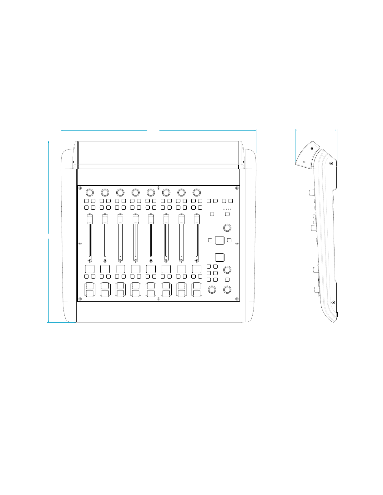
(482,881)
iQ Main Frame (8 faders + monitor controls)
20.45
(519,331)
19.01
4.38
(111,175)
Appendix A: Specications • 69
© 2014 Axia Audio - Rev 1.3.1
Page 78
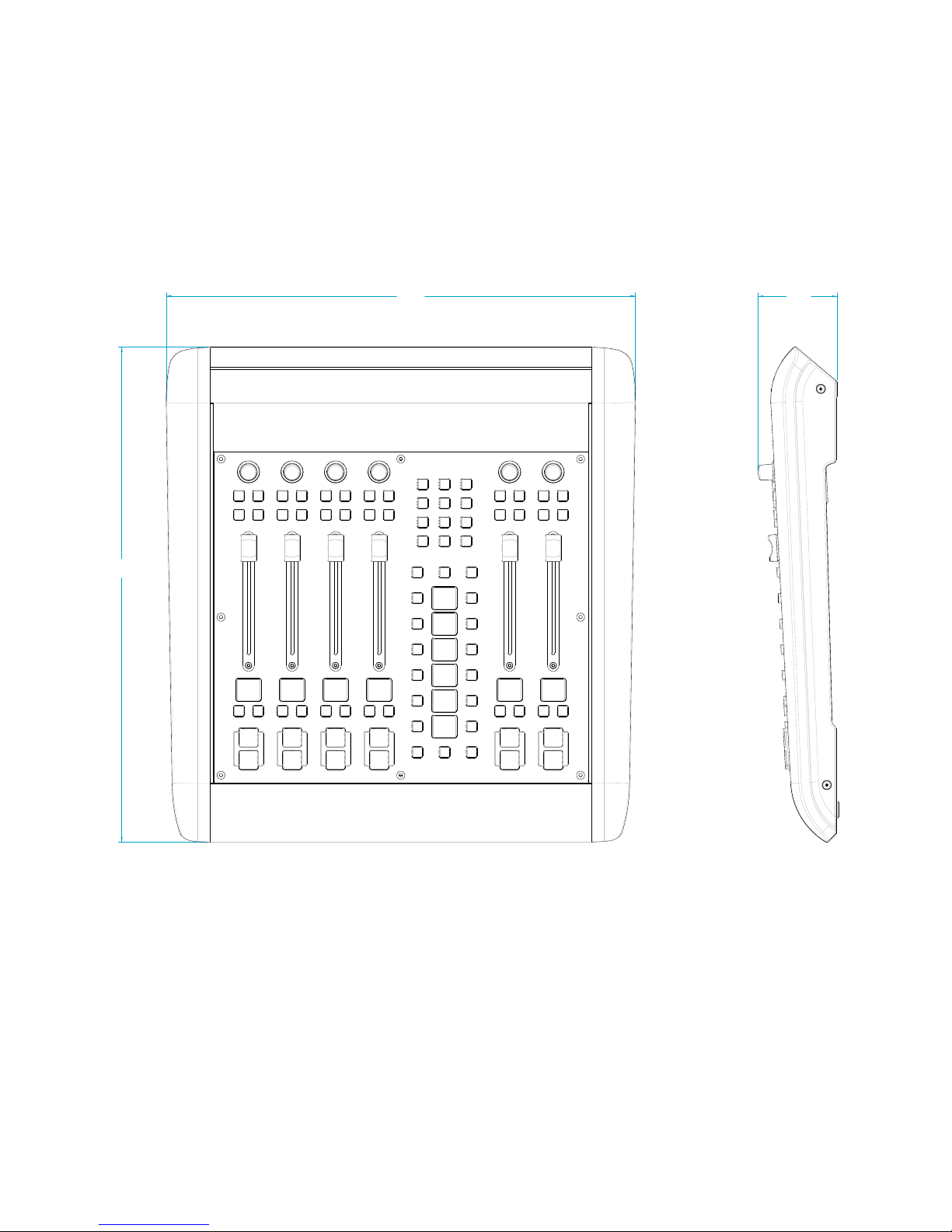
(462,376)
iQ Telco expansion frame (6 faders + call controller)
18.20
17.25
(438,051)
2.91
(73,963)
Appendix A: Specications • 70
© 2014 Axia Audio - Rev 1.3.1
Page 79
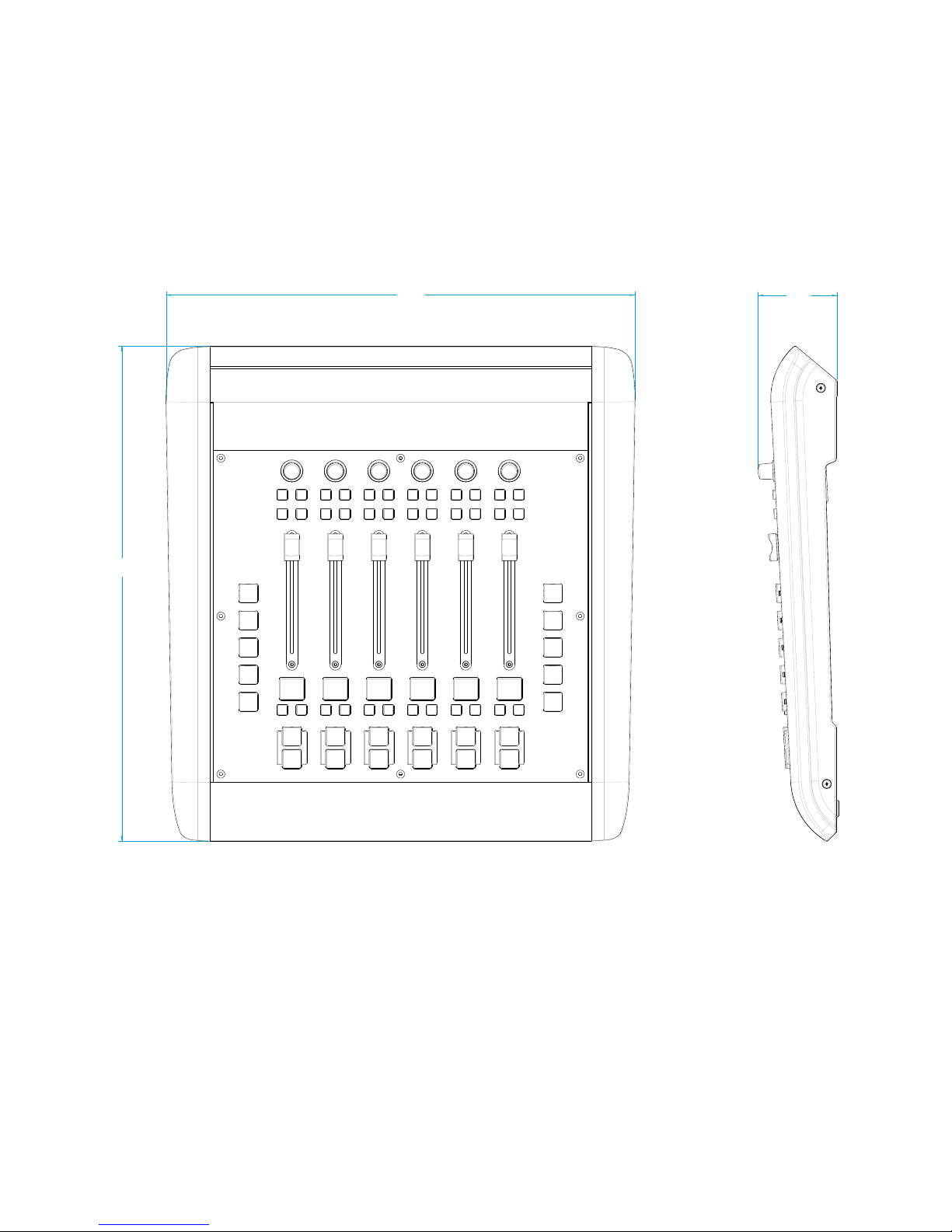
(462,376)
iQ button expansion frame (6 faders + programmable keys)
17.25
(438,051)
18.20
2.91
(73,989)
Appendix A: Specications • 71
© 2014 Axia Audio - Rev 1.3.1
Page 80
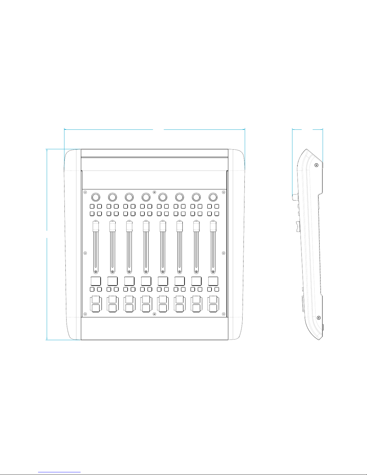
18.20
(462,376)
iQ 8-Fader expansion frame
17.25
(438,051)
2.91
(73,989)
Appendix A: Specications • 72
© 2014 Axia Audio - Rev 1.3.1
Page 81
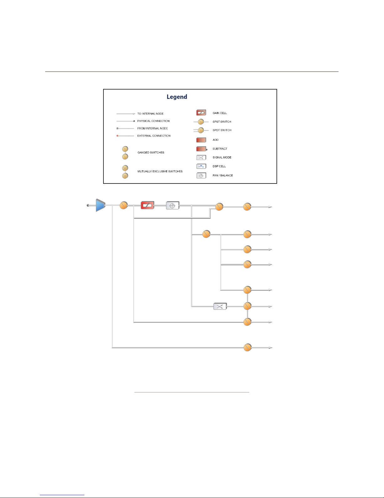
Appendix B: iQ Block Diagrams
POST
OPERATOR
MICROPHONE
SOURCE
Revised: January 2010
MUTE
FADER
PAN
FADER
PRE
FADER
MODE
STEREO
SUM TO LEFT
SUM TO RIGHT
PREVIEW
PGM.1ON
PGM.2
PGM.3
PGM.4
RECORD
PHONE
TALK TO X
Σ PREVIEW
Σ PROGRAM 1
Σ PROGRAM 2
Σ PROGRAM 3
Σ PROGRAM 4
Σ RECORD
Σ PHONE
Σ TALK TO X
Figure B-1 Block Diagram - Operator Microphone
Appendix B: Block DIagrams • 73
© 2014 Axia Audio - Rev 1.3.1
Page 82
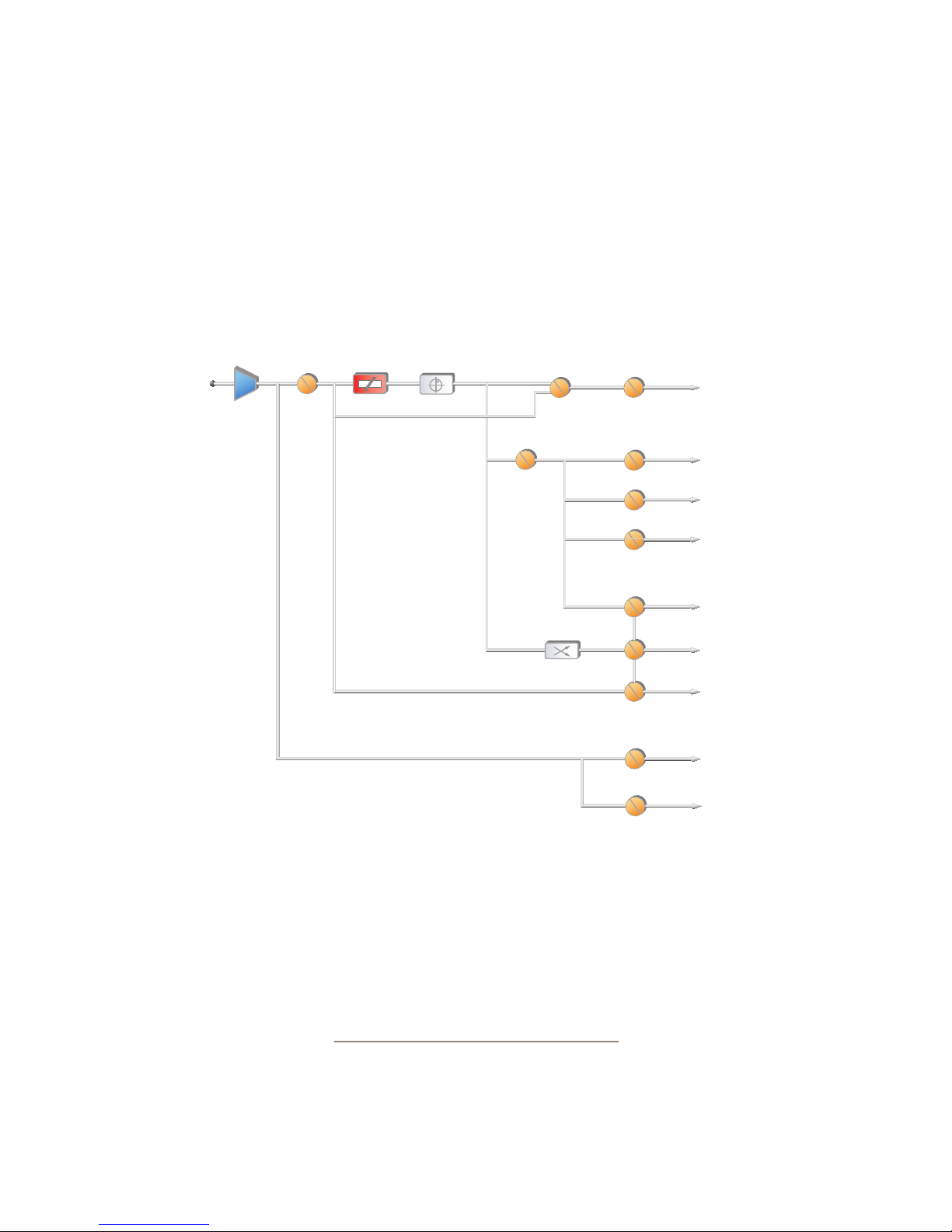
iQ Block Diagrams
POST
STUDIO GUEST
MICROPHONE
SOURCE
MUTE
FADER
PAN
FADER
PRE
FADER
MODE
STEREO
SUM TO LEFT
SUM TO RIGHT
PREVIEW
PGM.1ON
PGM.2
PGM.3
PGM.4
RECORD
PHONE
TALK TO X
TALK TO CR
Σ PREVIEW
Σ PROGRAM 1
Σ PROGRAM 2
Σ PROGRAM 3
Σ PROGRAM 4
Σ RECORD
Σ PHONE
Σ TALK TO X
Σ TALK TO CR
Revised: January 2010
Appendix B: Block DIagrams • 74
Figure B-2 Block Diagram - Guest Microphone
© 2014 Axia Audio - Rev 1.3.1
Page 83
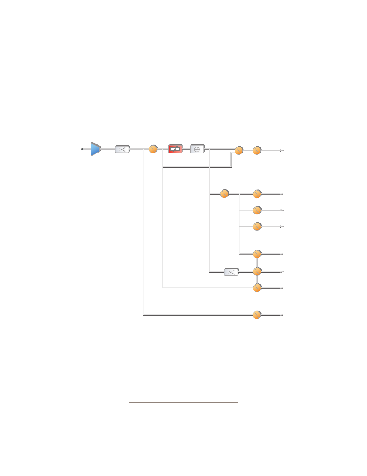
iQ Block Diagrams
LINE
SOURCE
MODE
STEREO
LEFT
RIGHT
SUM L+R
MUTE
FADER PAN
POST
FADER
PRE
FADER
MODE
STEREO
SUM TO LEFT
SUM TO RIGHT
PREVIEW
PGM.1ON
PGM.2
PGM.3
PGM.4
RECORD
PHONE
JOIN TALK TO X
Σ PREVIEW
Σ PROGRAM 1
Σ PROGRAM 2
Σ PROGRAM 3
Σ PROGRAM 4
Σ RECORD
Σ PHONE
Σ TALK TO X
Revised: January 2010
Figure B-3 Block Diagram - Line Source
Appendix B: Block DIagrams • 75
© 2014 Axia Audio - Rev 1.3.1
Page 84
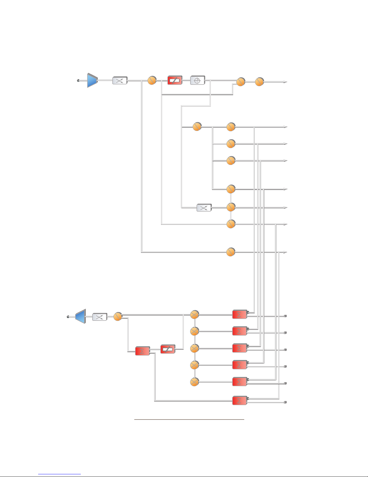
iQ Block Diagrams
PHONE
SOURCE
MODE
STEREO
LEFT
RIGHT
SUM L+R
MUTE
FADER PAN
SUM TO LEFT
SUM TO RIGHT
MODE
STEREO
POST
FADER
FADER
PGM.1ON
PGM.2
PGM.3
PGM.4
RECORD
PHONE
JOIN TALK TO X
PREVIEW
Σ PREVIEW
PRE
Σ PROGRAM 1
Σ PROGRAM 2
Σ PROGRAM 3
Σ PROGRAM 4
Σ RECORD
Σ PHONE
Σ TALK TO X
FEED TO
MODE
TALK
PHONE
SOURCE
Revised: January 2010
SUM TO LEFT
SUM TO RIGHT
TALK TO BOTH
Appendix B: Block DIagrams • 76
PGM 1
PGM 2
DIM
PGM 3
PGM 4
PHONE
Figure B-4 Block Diagram - Phone Source
© 2014 Axia Audio - Rev 1.3.1
PGM 1 MIX
PGM 2 MIX
PGM 3 MIX
PGM 4 MIX
PHONE MIX
TALK TO X MIX
Page 85
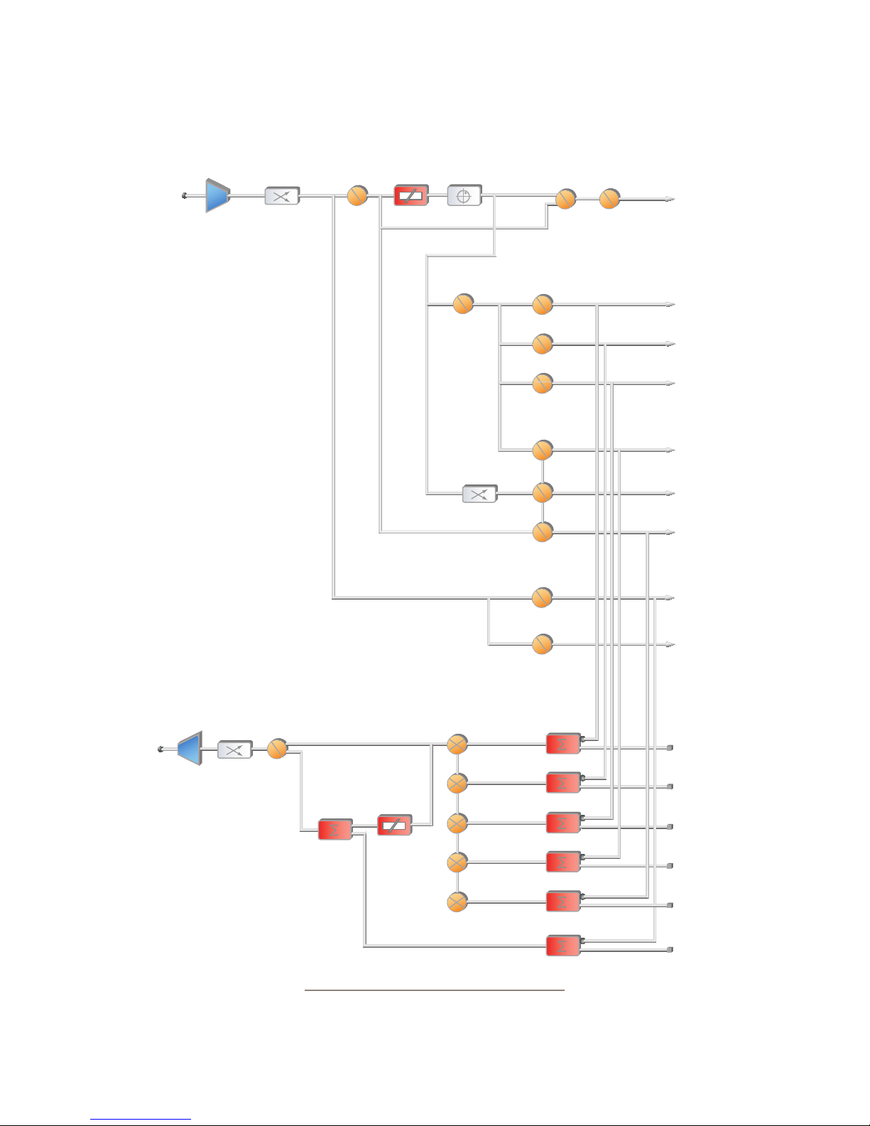
iQ Block Diagrams
CODEC
SOURCE
MODE
STEREO
LEFT
RIGHT
SUM L+R
MUTE
FADER PA N
SUM TO LEFT
SUM TO RIGHT
MODE
STEREO
POST
FADER
FADER
PGM.1ON
PGM.2
PGM.3
PGM.4
RECORD
PHONE
JOIN TALK TO X
PREVIEW
Σ PREVIEW
PRE
Σ PROGRAM 1
Σ PROGRAM 2
Σ PROGRAM 3
Σ PROGRAM 4
Σ RECORD
Σ PHONE
Σ TALK TO X
FEED TO
CODEC
SOURCE
Revised: January 2010
MODE
SUM TO LEFT
SUM TO RIGHT
TALK LEFT ONLY
TALK
TALK TO CR
PGM 1
PGM 2
DIM
PGM 3
PGM 4
PHONE
Figure B-5 Block Diagram - Codec Source
Σ TALK TO CR
PGM 1 MIX
PGM 2 MIX
PGM 3 MIX
PGM 4 MIX
PHONE MIX
TALK TO X MIX
Appendix B: Block DIagrams • 77
© 2014 Axia Audio - Rev 1.3.1
Page 86
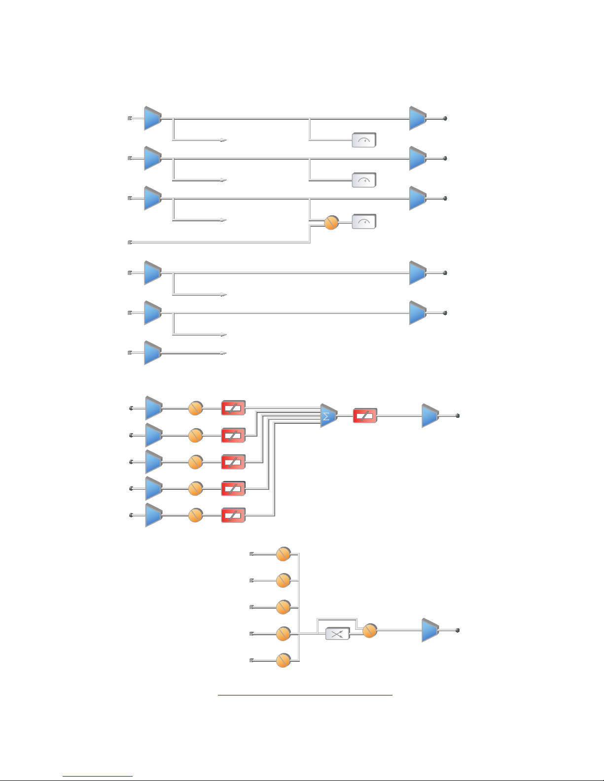
iQ Block Diagrams
∑
PGM 1 PGM 1 OUTPUT
PGM 1 METER
PGM 1 MIX
∑
PGM 2 PGM 2 OUTPUT
PGM 2 METER
PGM 2 MIX
∑
PGM 3 PGM 3 OUTPUT
PGM 3 METER
PGM 3 MIX
FOLLOW
MONITOR
MONITOR
METER
∑
PGM 4 PGM 4 OUTPUT
PGM 4 MIX
∑
RECORD RECORD OUTPUT
RECORD MIX
∑
PHONE
PHONE MIX
(STEREO)
(STEREO)
(STEREO)
(STEREO)
(STEREO)
VMIX1 IN 1
VMIX1 IN 2
VMIX1 IN 3
VMIX1 IN 4
VMIX1 IN 5
INPUT 1
INPUT 2
INPUT 3
INPUT 4
INPUT 5
FADER 1
FADER 2
FADER 3
FADER 4
FADER 5
PGM 1 MIX
PGM 2 MIX
PGM 3 MIX
PGM 4 MIX
VMIX
PGM 1
PGM 2
PGM 3
PGM 4
VMIX
VMIX
MASTER
Pass Stereo
Mono sum to left only
Mono sum to right only
Combine from left and right
MODE
VMIX OUTPUT
(STEREO)
VMODE OUTPUT
Revised: January 2010
Appendix B: Block DIagrams • 78
Figure B-6 Block Diagram - Master Output
© 2014 Axia Audio - Rev 1.3.1
Page 87
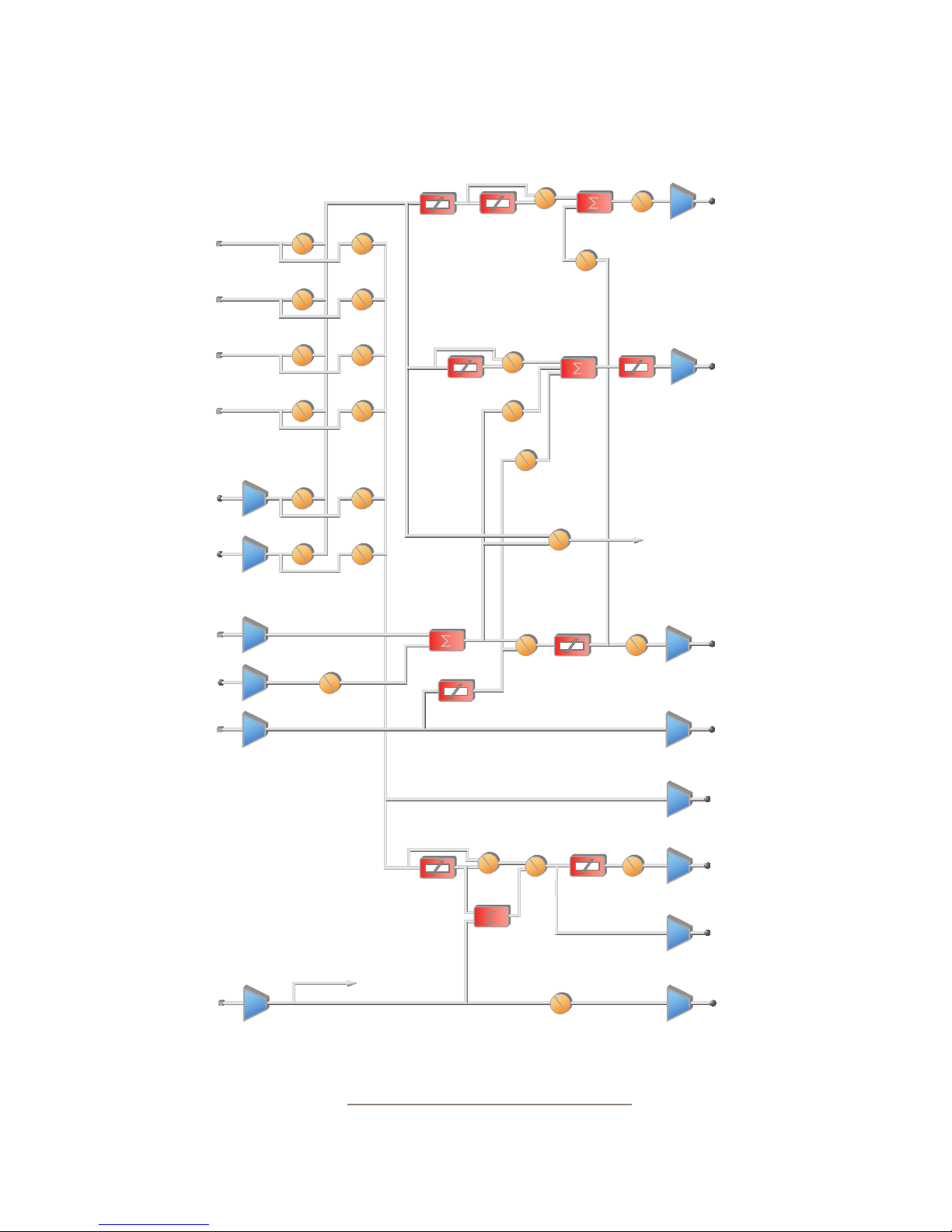
iQ Block Diagrams
PGM 1 MIX
PGM 2 MIX
PGM 3 MIX
PGM 4 MIX
EXTERNAL 1
EXTERNAL 2
∑
PREVIEW
EXT PREVIEW
CR: PGM1 STU: PGM1
CR: PGM2 STU: PGM2
CR: PGM3 STU: PGM3
CR: PGM4 STU: PGM4
CR: EXT1 STU: EXT1
CR: EXT2 STU: EXT2
EXTERNAL
PREVIEW IN
CR MON
VOLUME
DIM LEVEL
TALK
LEVEL
DIM LEVEL
CR HP
PREVIEW
IN CR HP
DIM
TALK
TO CR
TALK
TO CR
DIM
CR MON
PREVIEW
ACTIVE
PREVIEW
IN CR MON
PREVIEW
VOLUME
MUTE
CR MON
CR HP
VOLUME
MONITOR METER
MUTE
PREVIEW
CR MONITOR
OUTPUT
CR HEADPHONE
OUTPUT
PREVIEW
OUTPUT
∑
TALK TO CR
∑ TALK TO X
Revised: January 2010
DIM LEVEL
TALK TO X MIX
DIM
STUDIO
TALK TO
STUDIO
TALK TO EXTERNAL
STUDIO
VOLUME
Figure B-7 Block Diagram - Monitor Output
© 2014 Axia Audio - Rev 1.3.1
MUTE
STUDIO
TALK TO
CR OUTPUT
STUDIO GUEST
H/P OUTPUT
STUDIO MON
OUTPUT
STUDIO TALENT
H/P OUTPUT
TALK TO
EXT OUT
Appendix B: Block DIagrams • 79
Page 88

c tes, w sc
ng igtly t r.
M... s Er Gr.
Appendix B: Block DIagrams • 80
© 2014 Axia Audio - Rev 1.3.1
Page 89

Appendix C: Channel / IP Worksheets
The scalable nature of Axia Livewire audio networks makes it possible to construct systems of any size - from a
single room to an entire multi-studio facility.
Since Livewire components – Audio Nodes, Elements, StudioEngines, PowerStation, iQ, etc. – are connected with
Ethernet, each one requires a unique IP (Internet Protocol) address. IP addresses are four bytes long and are written
in “dotted decimal” form, with each byte represented decimally and separated by a period. For example, in the IP
address 193.32.216.9, the 193 is the value for the rst byte, 32 for the second, etc. Since a byte can hold values from
0 to 255, this is the range for each decimal value. If you run a public network, Host IP addresses are assigned to your
organization by your internet service provider and parceled out to individual host computers by your network admin-
istrator. He may give you this number to be entered manually, or could opt for DHCP (Dynamic Host Conguration
Protocol) to let your computer get the address automatically from a pool. Because Livewire devices are permanently
attached and because it is more desirable to know the IP address attached to a particular node (and perhaps assign
them in some kind of logical pattern), we do not support DHCP for our hardware nodes. Therefore, you will need to
enter an IP address into each node.
Livewire systems can support over 10,000 channels of audio; this necessitates giving each audio source or destina-
tion its own unique identier, called Channel ID numbers.
As you can imagine, keeping track of so many unique IP addresses and Channel ID numbers is a big job. There-
fore, on the next few pages, we’ve provided you with worksheets that you can use to keep track of the numbers you’ve
assigned.
A logical convention that is often followed will link the Livewire channel number to the last octet of the device IP
address. For example, if a node has an IP address of 192.168.1.12, the channel numbers assigned to the 8 sources of
that node might be 1201 through 1208.
For a more detailed explanation of IP addresses, subnet masks and related issues, we highly suggest that you refer
to “Network Engineering For Audio Engineers”, Chapter 8 of our Introduction to Livewire: IP Audio System Design
Reference and Primer.
Appendix D: Worksheets • 81
© 2014 Axia Audio - Rev 1.3.1
Page 90

Axia IP Address Assignment Worksheet
IP Address Device Name Location Notes
. . .
. . .
. . .
. . .
. . .
. . .
. . .
. . .
. . .
. . .
. . .
. . .
. . .
. . .
. . .
. . .
. . .
. . .
. . .
. . .
. . .
. . .
. . .
. . .
. . .
. . .
. . .
. . .
. . .
. . .
. . .
Appendix D: Worksheets • 82
© 2014 Axia Audio - Rev 1.3.1
Page 91

Axia Audio Channel Assignment Worksheet - SOURCES
Channel ID Number Device Name Device Location Notes
Appendix D: Worksheets • 83
© 2014 Axia Audio - Rev 1.3.1
Page 92

Axia Audio Channel Assignment Worksheet - DESTINATIONS
Channel ID Number Device Name Device Location Notes
Appendix D: Worksheets • 84
© 2014 Axia Audio - Rev 1.3.1
Page 93

Warranty
Axia Audio Limited Warranty
This Warranty covers “the Products,” which are dened as the various audio equipment, parts, software and acces-
sories manufactured, sold and/or distributed by TLS Corp., d/b/a Axia Audio (hereinafter “Axia Audio”).
With the exception of software-only items, the Products are warranted to be free from defects in material and
workmanship for a period of two (2) years from the date of receipt by the end-user. Software-only items are warranted
to be free from defects in material and workmanship for a period of 90 days from the date of receipt by the end-user.
This warranty is void if the Product is subject to Acts of God, including (without limitation) lightning; improper
installation or misuse, including (without limitation) the failure to use telephone and power line surge protection de-
vices; accident; neglect or damage.
EXCEPT FOR THE ABOVE-STATED WARRANTY, AXIA AUDIO MAKES NO WARRANTIES, EXPRESS
OR IMPLIED (INCLUDING IMPLIED WARRANTIES OF MERCHANTABILITY AND FITNESS FOR A PAR-
TICULAR PURPOSE).
In no event will Axia Audio, its employees, agents or authorized dealers be liable for incidental or consequential
damages, or for loss, damage, or expense directly or indirectly arising from the use of any Product or the inability to
use any Product either separately or in combination with other equipment or materials, or from any other cause.
In order to invoke this Warranty, notice of a warranty claim must be received by Axia Audio within the above-
stated warranty period and warranty coverage must be authorized by Axia Audio. If Axia Audio authorizes the perfor-
mance of warranty service, the defective Product must be delivered, shipping prepaid, to: Axia Audio, 1241 Superior
Avenue, Cleveland, Ohio 44114.
Axia Audio at its option will either repair or replace the Product and such action shall be the full extent of Axia
Audio’s obligation under this Warranty. After the Product is repaired or replaced, Axia Audio will return it to the party
that sent the Product and Axia Audio will pay for the cost of shipping.
Axia Audio’s authorized dealers are not authorized to assume for Axia Audio any additional obligations or liabili-
ties in connection with the dealers’ sale of the Products.
Axia Audio’s products are to be used with registered protective interface devices which satisfy regulatory require-
ments in their country of use.
Warranty • 85
© 2014 Axia Audio - Rev 1.3.1
Page 94

Axia Audio, a Telos Alliance Company • 1241 Superior Ave. • Cleveland, Ohio, 44114, USA • +1.216.241.7225 • www.AxiaAudio.com
 Loading...