

Page 1
element
Installation & User’s Guide
®
Revision 3.0 for:
• Element v2.x and higher
• StudioEngine v2.4.8x and higher
February, 2008
Page 2

USA Class A Computing Device
Information To User. Warning:
This equipment generates, uses, and can radiate ra-
dio-frequency energy. If it is not installed and used
as directed by this manual, it may cause interference
to radio communication. This equipment complies
with the limits for a Class A computing device, as
specified by FCC Rules, Part 15, Subpart J, which
are designed to provide reasonable protection against
such interference when this type of equipment is op-
erated in a commercial environment. Operation of
this equipment in a residential area is likely to cause
interference. If it does, the user will be required
to eliminate the interference at the user’s expense.
NOTE: Objectionable interference to TV or radio
reception can occur if other devices are connected to
this device without the use of shielded interconnect
cables. FCC rules require the use of only shielded
cables.
Canada Warning:
Important Safety Information
To prevent risk of electric shock: Disconnect power
cord before servicing. If fuse replacement is required,
please note: For continued protection against fire, re-
place fuse only with same type and value.
Caution
The installation and servicing instructions in the
manual are for use by qualified personnel only. To
avoid Electric Shock, do not perform any servicing
other than that contained in the operating instruc-
tions unless you are qualified to do so. Refer all ser-
vicing to qualified personnel.
Electrical Warning
To reduce the risk of electrical shock, do not expose
this product to rain or moisture. Keep liquids away
from the ventilation openings in the top and rear of
the unit. Do not shower or bathe with the unit.
“This digital apparatus does not exceed the Class A
limits for radio noise emissions set out in the Radio
Interference Regulations of the Canadian Depart-
ment of Communications.” “Le present appareil nu-
merique n’emet pas de bruits radioelectriques depas-
sant les limites applicables aux appareils numeriques
(de les Class A) prescrites dans le Reglement sur le
brouillage radioelectrique edicte par le ministere des
Communications du Canada.”
CE Conformance Information:
This device complies with the requirements of the
EEC Council Directives: 93/68/EEC (CE Marking);
73/23/EEC (Safety – low voltage directive); 89/336/EEC
(electromagnetic compatibility). Conformity is declared
to those standards: EN50081-1, EN50082-1.
This equipment is designed to be operated from
a power source that includes a third “grounding”
connection in addition to the power leads. Do not
defeat this safety feature. In addition to creating a
potentially hazardous situation, defeating this safety
ground will prevent the internal line noise filter from
functioning.
Ventilation Warning
The Axia StudioEngine and Power Supply/GPIO
Nodes require the free flow of air for adequate cool-
ing. Do not block the ventilation openings in the top
and rear of the unit. StudioEngine and the Power-
Supply/GPIO Node must be mounted with a blank
rack spacer above or damage may occur.
Failure to allow proper ventilation could damage the
unit or create a fire hazard. Do not place the unit on
a carpet, bedding, or other materials that could inter-
fere with the rear and top panel ventilation openings.
Page 3

Customer Service
We support you...
By Phone/Fax in the USA.
Customer service is available from 9:30 AM to 6:00 PM USA Eastern Time, Monday through Friday at
•
+1 216.241.7225. Fax: +1 216.241.4103.
By Phone/Fax in Europe.
Service is available from Axia Europe in Germany at +49 81 61 42 467. Fax: +49 81 61 42 402.
•
By E-Mail.
The address is [email protected].
•
Via World Wide Web.
The Axia Web site has a variety of information which may be useful for product selection and support. The URL
•
is http://www.AxiaAudio.com.
Feedback
We welcome feedback on any aspect of the Livewire products or this manual. In the past, many good ideas from
users have made their way into software revisions or new products. Please contact us with your comments.
Updates
The operations of Element and StudioEngine are determined largely by software. Periodic updates may become
available - to determine if this is the case, visit our web site periodically, or contact us for advice concerning whether
a newer release is more suitable to your needs.
Our electronic newsletter has announcements of major software updates for existing products, as well as keeping
you up to date on the latest Axia, Telos, and Omnia product releases.
To subscribe go to http://www.axiaaudio.com/news/eNews.htm.
Trademarks
Telos Systems, Axia Audio, Livewire, the Livewire Logo, the Axia logo, Element, SmartQ, Status Symbols, Zeph-
yr, Zephyr Xstream, Zephyr Xport, Omnia, the Omnia logo, and the Telos logo, are trademarks of TLS Corporation.
All other trademarks are the property of their respective holders.
Axia Audio
2101 Superior Ave. Cleveland, OH 44114 USA
+1 (216) 241-7225
Axia Europe
Johannisstraβ e 6, 85354 Freising, Germany
+49 81 61 42 467
Copyright © 2006 by TLS Corporation. Published by Axia Audio. We reserve the right to make improvements or changes in the prod-
ucts described in this manual, which may affec t the product specic ations, or to revise the manual without notice. All rights reserved.
Introduction • iii
©2008 Axia Audio — Rev. 3.0
Page 4

Notice
Feedback is welcome
All versions, claims of compatibility, trademarks, etc.
of hardware and software products not made by Axia
mentioned in this manual or accompanying material
are informational only. Axia makes no endorsement
of any particular product for any purpose, nor claims
any responsibility for operation or accuracy.
Warranty
This product is covered by a one year limited war-
ranty, the full text of which is included in the rear
section of this manual.
At Axia, we love to hear your feedback. If you find
anything in this manual that you feel needs clari-
fication or correction, please let me know: e-mail
About This Manual
This manual covers the details of the Element Stu-
dio Control Surface and StudioEngine. However it
is assumed in this document that you are familiar
with Livewire’s basic concepts, as outlined in the
companion Introduction to Livewire: System Design
Reference and Primer.
Service
If you have not done so, please review that mate-
You must contact Axia before returning any equip-
ment for factory service. Axia will issue a Return
Authorization number, which must be written on the
exterior of your shipping container. Please do not
include cables or accessories unless specifically re-
quested by the Technical Support Engineer at Axia.
Be sure to adequately insure your shipment for its
replacement value. Packages without proper autho-
rization may be refused. US customers please con-
tact Axia technical support at +1 (216) 241-7225. All
other customers should contact their local represen-
tative to arrange for service.
rial first. In it we explain the ideas that motivated
Livewire and how you can use and benefit from it,
as well as nitty-gritty details about wiring, connec-
tors, and the like. Since Livewire is built on standard
networks, we also help you to understand general
network engineering so that you have the full back-
ground for Livewire’s fundamentals. After reading
Introduction to Livewire you will know what’s up
when you are speaking with gear vendors and the
network guys that are often hanging around radio
stations these days.
New in Manual Version 3.0
We strongly recommend being near the unit when
you call, so our Support Engineers can verify infor-
mation about your configuration and the conditions
under which the problem occurs. If the unit must
return to Axia, we will need your serial number, lo-
cated on the rear panel.
This revision, in February, 2008, details the work-
ings of Element software Version 2.0. This version
represents a major upgrade, with many new features
and capabilities. Look for the “eyes” symbol that
highlights new or changed information throughout
the text.
Credit Where Credit’s Due
Axia Audio, a Telos Company
Deep bows from the waist go to John Makley, Milos
Nemcik, Gints Linis, Michael Dosch and the rest
of the Axia team in helping to proofread and fact-
check this manual. Thanks also to Bruce Wilkinson.
Kudos, guys — you are owed more beers than I can-
Introduction • iv
count. - c.n.
2101 Superior Avenue
Cleveland Ohio 44114 USA
Phone: +1.216.241.7225
Web: www.AxiaAudio.com
E-Mail: [email protected]
©2008 Axia Audio — Rev. 3.0
Page 5

Table of Contents
Warranty . . . . . . . . . . . . . . . . . . . . . . iv
Service . . . . . . . . . . . . . . . . . . . . . . . iv
New in Manual Version 3.0. . . . . . . . . . . . . iv
A Note From The President of Telos . . . . . . . . vii
A Note From The President of Axia . . . . . . . . viii
Quickstart . . . . . . . . . . . . . . . . . . . . . . . . ix
Making Connections. . . . . . . . . . . . . . . . . . ix
Software Setup. . . . . . . . . . . . . . . . . . . . . ix
Chapter One: Setup and Connections . . . . . . . . . 1
Introduction . . . . . . . . . . . . . . . . . . . . . . 1
Element Preliminary Setup . . . . . . . . . . . . . . 2
Connections and IP Configuration . . . . . . . . . 2
“Capturing” Your Console . . . . . . . . . . . . . 3
Short Navigation Tutorial . . . . . . . . . . . . . 4
IP Address Configuration. . . . . . . . . . . . . . 5
Clock Configuration . . . . . . . . . . . . . . . . 7
StudioEngine Quick Setup . . . . . . . . . . . . . . 8
Connections and IP Configuration . . . . . . . . . 8
StudioEngine Channel Settings. . . . . . . . . . . 9
Set Your Console Type . . . . . . . . . . . . . . . 10
Advanced Settings . . . . . . . . . . . . . . . . . . . 10
Chapter Two: Configuring Inputs . . . . . . . . . . . 11
Understanding Source Profiles . . . . . . . . . . . . 11
Source Profile Setup . . . . . . . . . . . . . . . . . . 11
Source Profile Options . . . . . . . . . . . . . . . 11
Adding Backfeeds and GPIO to a Source Profile . 18
Chapter Three: Configuring GPIO . . . . . . . . . . . 21
GPIO Port Definitions . . . . . . . . . . . . . . . . . 21
Assigning GPIO to a Source. . . . . . . . . . . . . . 34
A word about the GPIO Ports . . . . . . . . . . . . . 35
Input Connections . . . . . . . . . . . . . . . . . 35
Output Connections . . . . . . . . . . . . . . . . 35
Chapter Four: Element Operations . . . . . . . . . . . 37
Overview. . . . . . . . . . . . . . . . . . . . . . . . 37
Displays . . . . . . . . . . . . . . . . . . . . . 37
Show Profiles . . . . . . . . . . . . . . . . . . 37
Sources, Channels and Faders . . . . . . . . . 37
Mix-Minus . . . . . . . . . . . . . . . . . . . . 38
GPIO . . . . . . . . . . . . . . . . . . . . . . 38
Monitor Module and SoftKnobs. . . . . . . . . 38
Software . . . . . . . . . . . . . . . . . . . . . 38
Control Callout . . . . . . . . . . . . . . . . . . . . 38
Element with Standard Monitor Module . . . . . . 39
Element with 2-Fader Phone Module and 2-Fader +
Monitor Module . . . . . . . . . . . . . . . . . . 40
Element Stereo Main Screen Overview. . . . . . . 41
Control Details. . . . . . . . . . . . . . . . . . . . . 42
General Fader Controls . . . . . . . . . . . . . . 42
4-Phone Module Channel Controls . . . . . . . . 43
Call Controller + 2Fader Phone Module Controls 44
Production Module Controls . . . . . . . . . . . . 45
Standard Monitor Module Controls . . . . . . . . 46
Nav Keys & Control Knob. . . . . . . . . . . . 46
Channel Options Section . . . . . . . . . . . . 46
Delay Section . . . . . . . . . . . . . . . . . 52
Monitor Section . . . . . . . . . . . . . . . . . 52
Global Options Section . . . . . . . . . . . . . 53
Timer Section . . . . . . . . . . . . . . . . . 58
Record Mode Section . . . . . . . . . . . . . . 59
“Magic Key” Sequences for Standard Monitor
Module . . . . . . . . . . . . . . . . . . . . . 59
Monitor + 2-Fader Module Controls. . . . . . . . 59
Channel Options Controls . . . . . . . . . . . 60
Monitor Section . . . . . . . . . . . . . . . . . 66
Other Controls . . . . . . . . . . . . . . . . . 70
Timer Section . . . . . . . . . . . . . . . . . 71
Record Mode Section . . . . . . . . . . . . . . 73
“Magic Key” Sequences for Monitor + 2-Fader
Module . . . . . . . . . . . . . . . . . . . . . 73
Source-Specific Channel Controls . . . . . . . . . 73
CR Operator Mic Channel Operation . . . . . 74
Producer Microphone Channel Operation . . . 74
CR Guest Microphone Channel Operation . . . 74
Studio Microphone Channel Operation. . . . . 74
Line Channel Operation . . . . . . . . . . . . 77
Phone Channel Operation . . . . . . . . . . . 79
Codec Channel Operation . . . . . . . . . . . 79
Chapter Five: Show Profiles . . . . . . . . . . . . . . . 85
Creating A Show Profile . . . . . . . . . . . . . . . . 85
Build A Show . . . . . . . . . . . . . . . . . . . . 85
Capture It! . . . . . . . . . . . . . . . . . . . . . 85
Show Profile Options . . . . . . . . . . . . . . . . . 86
Introduction • v
©2008 Axia Audio — Rev. 3.0
Page 6

The Channel Description Screen . . . . . . . . . . 86
Channel Description Section . . . . . . . . . . 87
Individual Headphones Section . . . . . . . . . 89
The Auxiliary Send / Return Description Screen . . 89
Monitor Section Screen. . . . . . . . . . . . . . . 90
General Monitor Options . . . . . . . . . . . . 90
Sources for External 1 & 2 Section . . . . . . . 91
Control Room Monitor (Monitor 1) Options . . 91
Control Room (Monitor 1) Headphone Options 91
Studio Monitor (Monitor 2) Options . . . . . . 92
Master Module Control Lock Map . . . . . . . 93
Save and Exit . . . . . . . . . . . . . . . . . . 93
Record Mode Screen . . . . . . . . . . . . . . . . 93
Record Mode Configuration. . . . . . . . . . . 93
Group Start Screen . . . . . . . . . . . . . . . . . 94
Phone Screen . . . . . . . . . . . . . . . . . . . . 94
Chapter 6: Virtual Mixer . . . . . . . . . . . . . . . . 95
Constructing Virtual Mixes with VMIX. . . . . . . . 95
StudioEngine VMIX Controls. . . . . . . . . . . . 96
Element VMIX Controls . . . . . . . . . . . . . . 97
Enabling Element control of VMIX . . . . . . . 97
VMIX Control Description . . . . . . . . . . . 97
What can you do with a VMIX? . . . . . . . . . . 99
GPIO control of your VMIX. . . . . . . . . . . 99
PathfinderPC assisted VMIX . . . . . . . . . . 99
Manipulating Streams With VMODE . . . . . . . . . 100
What does VMODE do? . . . . . . . . . . . . . . 100
VMODE Controls. . . . . . . . . . . . . . . . . . 100
What can you do with VMODE? . . . . . . . . . . 102
Chapter 7: Advanced Element Controls . . . . . . . . 107
Element Configuration Screens . . . . . . . . . . . . 107
The Element Control Center . . . . . . . . . . . . 107
The Setup Menu . . . . . . . . . . . . . . . . . . 107
The Customize Menu . . . . . . . . . . . . . . . . 108
The Log and Log History Menu . . . . . . . . . . 109
The Screenshot Menu. . . . . . . . . . . . . . . . 109
The Module Information Menu. . . . . . . . . . . 109
The Firmware Update Menu . . . . . . . . . . . . 110
CAN Bus Information Manu . . . . . . . . . . . . 110
Brightness Control Menu. . . . . . . . . . . . . . 110
Phone Channels Menu . . . . . . . . . . . . . . . 111
User Modules Menu . . . . . . . . . . . . . . . . 111
Introduction • vi
GPIO Configuration Menu . . . . . . . . . . . . . 111
Script Information Menu . . . . . . . . . . . . . . 111
V-Mixer Menu . . . . . . . . . . . . . . . . . . . 111
NTP Menu . . . . . . . . . . . . . . . . . . . . . 111
Engine Menu . . . . . . . . . . . . . . . . . . . . 111
Sources & Profiles Configuration Menu . . . . . . 111
Chapter 8: StudioEngine Controls . . . . . . . . . . . 113
StudioEngine Configuration Screens . . . . . . . . . 113
The Main Menu. . . . . . . . . . . . . . . . . . . 113
The Fader Channels Menu . . . . . . . . . . . . . 113
The Return & Monitor Inputs Menu . . . . . . . . 113
The Program & Monitor Outputs Menu . . . . . . 114
The VMIX & VMODE Menu . . . . . . . . . . . . 115
Stream Statistics Menu . . . . . . . . . . . . . . . 115
The Engine ID Menu . . . . . . . . . . . . . . . . 115
Console ID Menu. . . . . . . . . . . . . . . . . . 116
System Menu . . . . . . . . . . . . . . . . . . . . 116
Diagnostics Menu . . . . . . . . . . . . . . . . . 117
Appendix A: Table of Inputs and Outputs . . . . . . . 121
Appendix B: Block Diagrams . . . . . . . . . . . . . . 123
Appendix C: FAQ / Diagnostics / Maintenance. . . . . 135
Installing A New Module . . . . . . . . . . . . . . . 137
Module Diagnostics . . . . . . . . . . . . . . . . . . 140
Fader Cleaning Procedures . . . . . . . . . . . . . . 141
Appendix D: Working With Phone Hybrids . . . . . . 143
Telos 2101 Multi-Studio Talkshow System . . . . . . 148
Telos Two ISDN Hybrid . . . . . . . . . . . . . . . 152
Telos One and Delta Hybrids . . . . . . . . . . . . . 153
Telos ONE-x-Six, Direct Interface and 1A2 Systems 154
Appendix E: Accessory User Panels. . . . . . . . . . . 155
Installing a CANBus Accessory Panel . . . . . . . 155
Installing a GPIO Accessory Module . . . . . . . 156
Appendix F: Channel / IP Worksheets . . . . . . . . . 159
Appendix G: CE Declaration of Conformity . . . . . . 163
Warranty . . . . . . . . . . . . . . . . . . . . . . . . . 165
©2008 Axia Audio — Rev. 3.0
Page 7

A Note From The President of Telos
It’s been a tradition since Telos’ very first product, the
Telos 10 digital phone system, that I share a few words
with you at the beginning of each manual. So here goes.
In radio broadcast studios we’re still picking up the
pieces that have fallen out from the digital audio revolu-
tion. We’re not using cart machines anymore because
PCs are so clearly a better way to store and play audio.
We’re replacing our analog mixing consoles with digital
ones and routing audio digitally. But we’re still using
decades-old analog or primitive digital methods to con-
nect our gear. Livewire has been developed by Telos to
provide a modern PC and computer network-oriented
way to connect and distribute professional audio around
a broadcast studio facility.
Your question may be, “Why Telos? Don’t you guys
make phone stuff?” Yes, we certainly do. But we’ve al-
ways been attracted to new and better ways to
make things happen in radio facilities. And
we’ve always looked for opportunities to
make networks of all kinds work for broad-
casters. When DSP was first possible, we used
it to fix the ages-old phone hybrid problem. It
was the first use of DSP in radio broadcasting.
When ISDN and MP3 first happened, we saw
the possibility to make a truly useful codec. We were the
first to license and use MP3 and the first to incorporate
ISDN into a codec. We were active in the early days of
internet audio, and the first to use MP3 on the internet.
Inventing and adapting new technologies for broadcast
is what we’ve always been about. And we’ve always
been marrying audio with networks. It’s been our pas-
sion right from the start. In our genes, if you will. As a
pioneer in broadcast digital audio and DSP, we’ve grown
an R&D team with a lot of creative guys who are open-
eyed to new ideas. So it’s actually quite natural that we
would be playing marriage broker to computer networks
and studio audio.
What you get from this is nearly as hot as a couple
on their wedding night: On one RJ-45, two-way multiple
audio channels, sophisticated control and data capabil-
ity, and built-in computer compatibility. You can use
Livewire as a simple sound card replacement – an audio
interface connecting to a PC with an RJ-45 cable. But
Introduction • vii
©2008 Axia Audio — Rev. 3.0
Page 8
A Note From The President of Axia
couldn’t communicate in a meaningful way – strange,
considering that PCs everywhere were being networked,
Nearly 20 years ago, I designed my first broadcast
console for PR&E. I look back on that time with great
fondness; we were building bullet-proof boards for the
world’s most prestigious broadcasters, making each new
console design bigger and fancier to accommodate a
wider variety of source equipment and programming
styles. The console was the core of the studio; all other
equipment was on the periphery.
Then things changed: the PC found its way into
broadcast audio delivery and production. At first, PC
audio applications were simple, used only by budget
stations to reduce operating expenses. But soon the ap-
plications evolved and were embraced by larger stations.
Slowly, the PC was taking center stage in the radio stu-
dio.
Like many, I was captivated by the PC. Stations
retired carts, phonographs, open-reel decks,
cassettes — even more modern digital equip-
ment such as DAT and CD players, replac-
ing all with PC apps. Client/server systems
emerged and entire facilities began using PCs
to provide most – or all – of their recorded
audio. Yet consoles continued to treat PCs as
nothing more than audio peripherals. I knew
that we console designers were going to have to rethink
our designs to deal with computer-centric studios.
During this time, traditional broadcast console com-
panies began producing digital versions. But early digi-
tal consoles were nearly identical in form and function
to their analog predecessors. It took a fresh look from a
European company outside broadcasting to merge two
products – audio routing switchers and broadcast con-
soles – into a central processing engine and attached
control surface. Eventually nearly every console and
routing switcher company followed suit, and a wide va-
riety of digital “engines” and control surfaces flooded
the market.
But, advanced as these integrated systems were, they
still handled computer-based audio sources like their
fast becoming the world’s most popular and powerful
communication tool.
Then a group of Telos engineers developed a method
of using Ethernet to interconnect audio devices, allow-
ing computers and consoles, controllers and peripherals
to interact smoothly and intelligently. Powerful, flex-
ible networks had finally come to our studios. As with
the transition from carts to computers, the benefits are
many and impressive. A few networked components can
replace routing switchers, consoles, processing periph-
erals, sound cards, distribution amps, selector switches
and myriad related devices.
This deceptively simple networked system costs a
fraction of other approaches, yet has capabilities sur-
passing anything else. The system is modular and can
be used to perform discrete functions in a traditional
environment. Concurrently, it easily scales to
serve both the humblest and the very largest
of facilities. Console, router, and computer
work in harmony.
So, equipped with this new technology
and countless ideas, we launch Axia, the new-
est division of Telos. Axia is all about deliv-
ering innovative networked audio products
to future-minded broadcasters. On behalf of our entire
team, I welcome you as a charter client. Axia is the cul-
mination of nearly 40 man-years of some of the most
ambitious R&D ever applied to the radio industry. And
this is only the beginning. We have more products, in-
novations, and partnerships in the pipeline.
You already know your Axia system is unlike any-
thing else. So it shouldn’t be surprising that your new
system is loaded with new thinking, new approaches,
and new ideas in virtually every conceivable area. Some
concepts will challenge your traditional ideas of studio
audio systems, but we’re certain that once you have ex-
perienced the pleasures of the networked studio, you’ll
never want to go back. And now, for something com-
pletely different...
analog ancestors. Sure, the router and console engine
were now integrated, but the most important studio ele-
ment – the PC – was stuck in the past, interfaced with
Introduction • viii
100-year-old analog technology. The PC and console
Michael “Catfish” Dosch
February 2004
©2008 Axia Audio — Rev. 3.0
Page 9
Quickstart
The following chapters of this manual will give you
an in-depth understanding of the capabilities of your
new Element, from installation to advanced functions.
But maybe you’re the sort who really doesn’t want to
read a manual – you want to open up the boxes and play!
This Quickstart section isn’t meant to take the place of
the following manual chapters, but it will help you get
everything connected fast, and point you to the parts
of the manual you’ll need to get up and running with a
minimum of fuss.
on the switch.
Packed with your Element is a cable with 6-pin
4.
Molex™ connectors. This is the power/commu-
nications cable. Lift the Element meter panel and
connect the end of the cable without the strain
relief to the corresponding port on the Element
connection panel. Connect the other end of the
cable to one of the jacks labeled “48VDC OUT-
PUT & COMM” on the back of your Element
GPIO Node/Power Supply unit.
Connect all Audio Node power cords and plug
5.
them into your studio’s power receptacles.
“Capture” your console using the instructions in
6.
Chapter 1, Page 3 of this manual.
Follow the instructions found in Chapter 1 to
7.
configure IP address settings for El-
ement and the StudioEngine.
Refer to the User’s Manuals
8.
packed with your other Axia
Audio Nodes for information on
how to configure IP addresses for
these units.
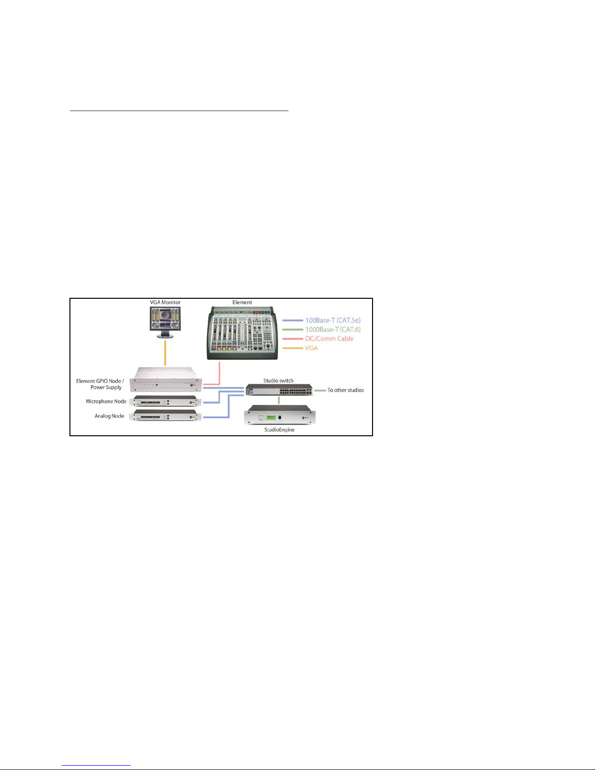
Making Connections
You’ve probably unpacked your boxes and are sitting
next to a pile of Axia gear, wondereing what to do first.
Take a look at the diagram above: it represents a typ-
ical Livewire-connected radio studio. Here’s what you
should do to get going:
Using CAT.5e or CAT.6 Ethernet cable, connect
1.
all of your Axia Audio Nodes (Analog, AES/EBU,
Microphone and Router Selector) to 100Base-T
ports on your studio’s Ethernet switch.
Use CAT.6 Ethernet cable to connect your
2.
StudioEngine to a Gigabit (1000Base-T) port on
the switch.
Use another CAT.5e or CAT.6 cable to connect
3.
the Ethernet port on the back of the Element
GPIO Node/Power Supply to a 100Base-T port
Software Setup
When you’ve completed physi-
cally connecting your Axia hardware, read through the
remainder of this manual to begin configuring the soft-
ware options that determine how your new Element will
operate.
Chapter 2, “Configuring Inputs,” explains how to
•
generate Source Profiles and construct backfeeds for
selected sources.
Chapter 3, “Configuring GPIO,” tells how to associ-
•
ate routable logic commands with any audio source.
Chapter 4, “Element Operations,” takes you under
•
the hood to explore in-depth software options.
Chapter 5, “Show Profiles,” illustrates how to set and
•
save unique “snapshots” tailored for specific opera-
tional situations that can be recalled whenever the
need arises.
Enjoy your new Element! q
Introduction • ix
©2008 Axia Audio — Rev. 3.0
Page 10

Lig n, gles
t acn
Elm ts.
Introduction • x
©2008 Axia Audio — Rev. 3.0
Page 11

Chapter One:
Setup and Connections
Introduction
There’s nothing quite as much fun as taking some-
thing new out of its box. That sense of excitement as
protective packaging is stripped away; that “new gear”
smell… it’s exhilarating!
If you’re reading this, there’s a 99.9836% chance that
you’ve done just that, and are now sitting in the middle
of a room surrounded by packing material and a large
wooden crate, admiring your new Element, its GPIO
Node/Power Supply and StudioEngine — and wonder-
ing what to do next.
But before you dig in, be advised that you need to
assemble the rest of your Livewire network first. Be-
cause so much of the Element configuration process de-
pends upon having access to audio sources and destina-
tions, you must connect and configure your other Axia
peripherals (Audio Nodes, GPIO Nodes, Router Selec-
tors, etc.) prior to configuring Element, according to the
instructions supplied with each. Once you’ve done that,
come on back and we’ll get started.
Be Prepared
This chapter will show you how to get you up and
running. We’ll install the Element console and its power
supply first, followed by the StudioEngine.
Before you dive into the hardware, you’ll need to de-
termine a range of IP addresses to assign to each studio
and log each device’s IP as you assign it; Appendix F
contains an IP Assignment Worksheet you can use for
this purpose. IP addresses used in an Axia network must
be valid Unicast IP addresses. Determine your network’s
subnet mask settings at the same time (typically this val-
ue is set at 255.255.255.0 for intranet applications).
Unicast vs. Multicast IP Addresses: Data
is routed over IP networks in one of two ways:
point-to-point unicast or multicast.
Livewire devices use common TCP/IP unicast
IP addresses for control and web browser access. These are numbers you assign within
the range used by your network. Since most
Livewire networks are not intended to be accessed via the Internet, we recommend you use
the non-routable IP addresses in the range of
192.168.0.0 to 192.168.255.255. These IP ad-
dresses have been set aside specically for use
with local networks.
Multicast allows ef cient one-to-many connections, so Livewire uses that for its audio streams,
source advertising, and synchronization signals.
You do not need to assign these multicast addresses because the system does this automatically.
For more information on network construction,
please refer to our companion Introduction to
Livewire: System Design Reference and Primer
available at www.AxiaAudio.com/downloads/ .
To install Element in your studio furniture, you’ll
need to prepare a cutout in the countertop. A dimen-
sional drawing with all pertinent measurements is found
just prior to this manual’s Appendix A. Make certain that
there’s adequate clearance inside the furniture for the
required power cable entry into the console; knockout
plugs are located at both bottom rear corners of Element
for cable routing access.
To configure Element, you’ll need a computer. Any
Windows desktop or notebook PC with an Ethernet port
and a standard Internet browser is acceptable.
For cable connections, CAT. 6 Ethernet cable is re-
quired. Axia strongly recommends shielded CAT. 6 if
your studio design calls for cable runs through areas
containing high levels of RF. (For greater detail on ca-
ble selections, we again recommend you read The Axia
Guide to Choosing Category Cable available from www.
AxiaAudio.com/tech/ .)
Always make certain that power has been applied to
your studio’s Ethernet switch before powering any other
Axia components.
1: Setup & Connections • 1
©2008 Axia Audio — Rev. 3.0
Page 12
Element Preliminary Setup
If you haven’t done so yet, it’s time to get your
Element out of its packing crate. This is a two-person
job, so grab a partner.
Important: Like any electronic device, Element
can be affected by static electricity. Use of a
personal grounding device is strongly recommended during transport.
Position one person at each end of Element and,
grasping the metal enclosure at the bottom, simulta-
neously lift upward out of the shipping crate. Remove
packing materials and store them in the crate for future
use. Carefully lower Element into your counter top cut-
out, taking care to lower both sides at an equal rate to
avoid becoming jammed in the cabinetry.
Important: Element is a drop-in style control
surface and requires a countertop cutout. For
cutout dimensions, please refer to Appendix A.
Important: Your Element MUST be grounded. Grounding reduces the risk of electric
shock by providing a “path of least resistance”
for electric current. Improper grounding can
result in a risk of electric shock.
Check with a qualied electrician if you are in
doubt about how to properly ground this equipment. If your local electrical code prohibits the
use of a Station Ground for this purpose, as de-
scribed above, use the specic “Safety Ground”
your local regulations mandate.
Rack-mount the GPIO Node/Power Supply unit
1.
and connect it to a 100Base-T port on your studio’s
Ethernet switch using CAT. 6 cable. Do not power up
the Power Supply yet.
Figure 1-2: Accessing Element’s connection panel.
Unpack the GPIO Node/Power Supply that came
with your Element and place it in its rack.
Connections and IP Conguration
Connections
Cable connections for Element are entirely different
from any other mixing surface you may be familiar with.
There are no audio inputs; Element needs only a single
data / power connection to operate.
Element must be connected to a grounded metal per-
2.
manent wiring system or other equipment grounding
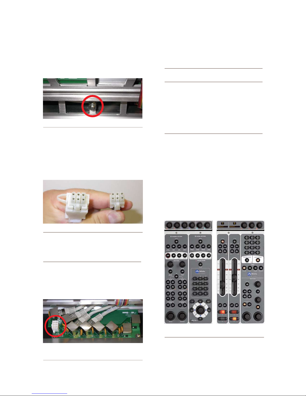
conductor using the threaded grounding stud located
inside the connections bay. Open the bay by flipping
open the overbridge above the faders, as shown in
Figure 1-2. For ground sources, we recommend, in
order of preference:
“Station Ground,” the heavy copper strap found in
»
the walls and floors of many radio studios.
VGA
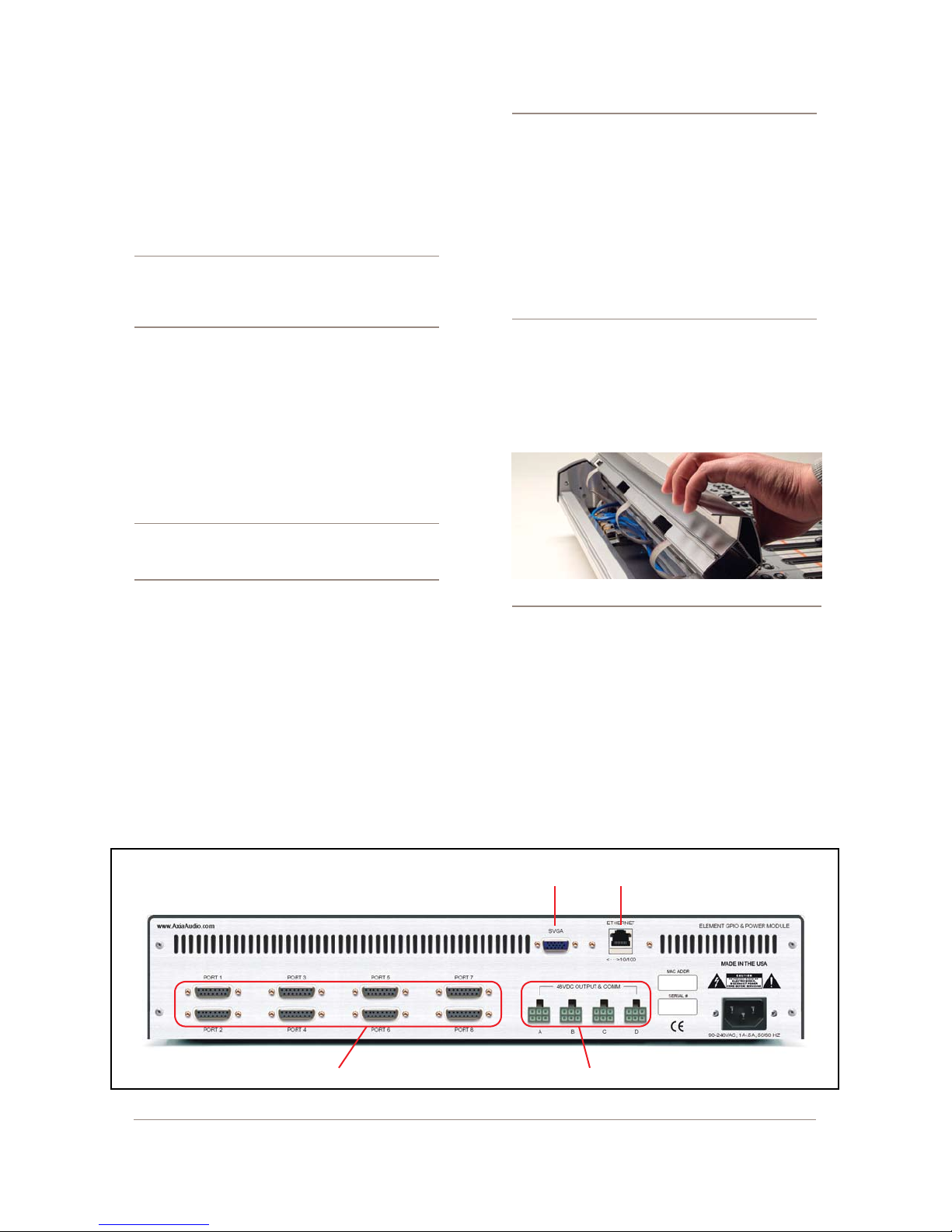
Display
Ethernet
Port
GPIO Por ts DC Power - CANbus to Element
Figure 1-1: Rear panel of Element GPIO/Power Supply showing connections.
1: Setup & Connections • 2
©2008 Axia Audio — Rev. 3.0
Page 13
AC Safety Ground — the “3rd prong” of a nearby
»
outlet.
A bonded electrical conduit.
»
#12 AWG GREEN stranded wire is the minimum
wire gauge acceptable for grounding Element.
Figure 1-3: Locating the grounding stud.
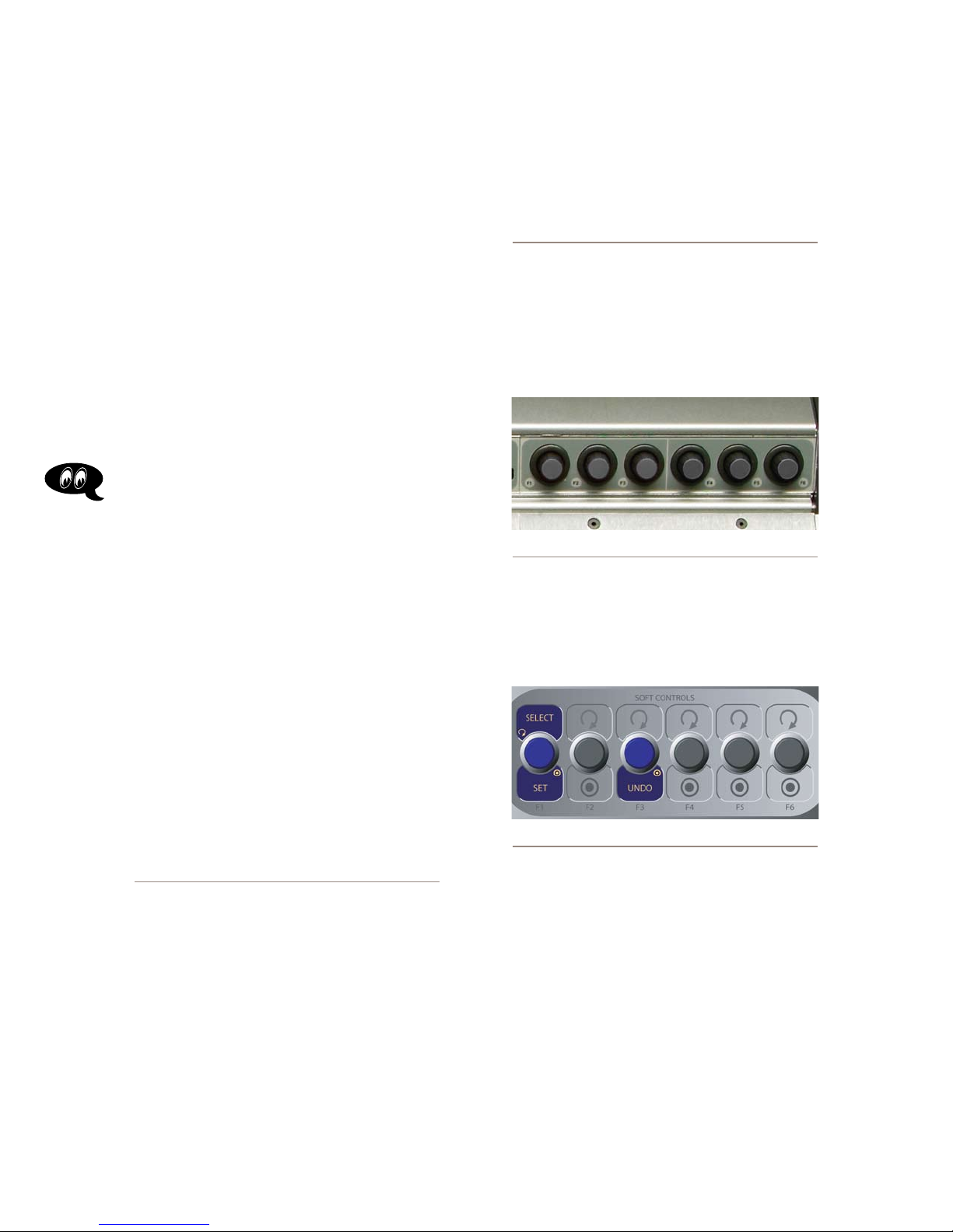
One end of the Element power / communication ca-
3.
ble is fitted with a strain relief. Connect this end to
any one of the four Molex connectors on the back of
the Element GPIO Node/Power Supply. Connect the
other end to the Molex socket on the Element con-
nection panel.
ports on the Element connection panel to
an Ethernet switch. These ports are for con-
nection of Element fader and accessory modules only; connecting them to a powered Ethernet switch could damage the board’s electronics
and void your warranty.
What is CANbus? Controller Area Network
(CAN) is a multicast shared serial bus standard,
originally developed in the 1980s by Robert
Bosch GmbH, for connecting electronic control
units (ECUs). Although initially created for automotive purposes, nowadays it is used in many
embedded control applications.
The CAN data link layer protocol is standardized
in ISO 11898-1 (2003).
5.
Whew, that was hard work. Better have a beer. (We’ll
have one for you, too.)
“Capturing” Your Console
Upon power-up of your Element, some or all of
the alphanumeric displays above the faders may read
INACTIVE. This means that the Element CPU must be
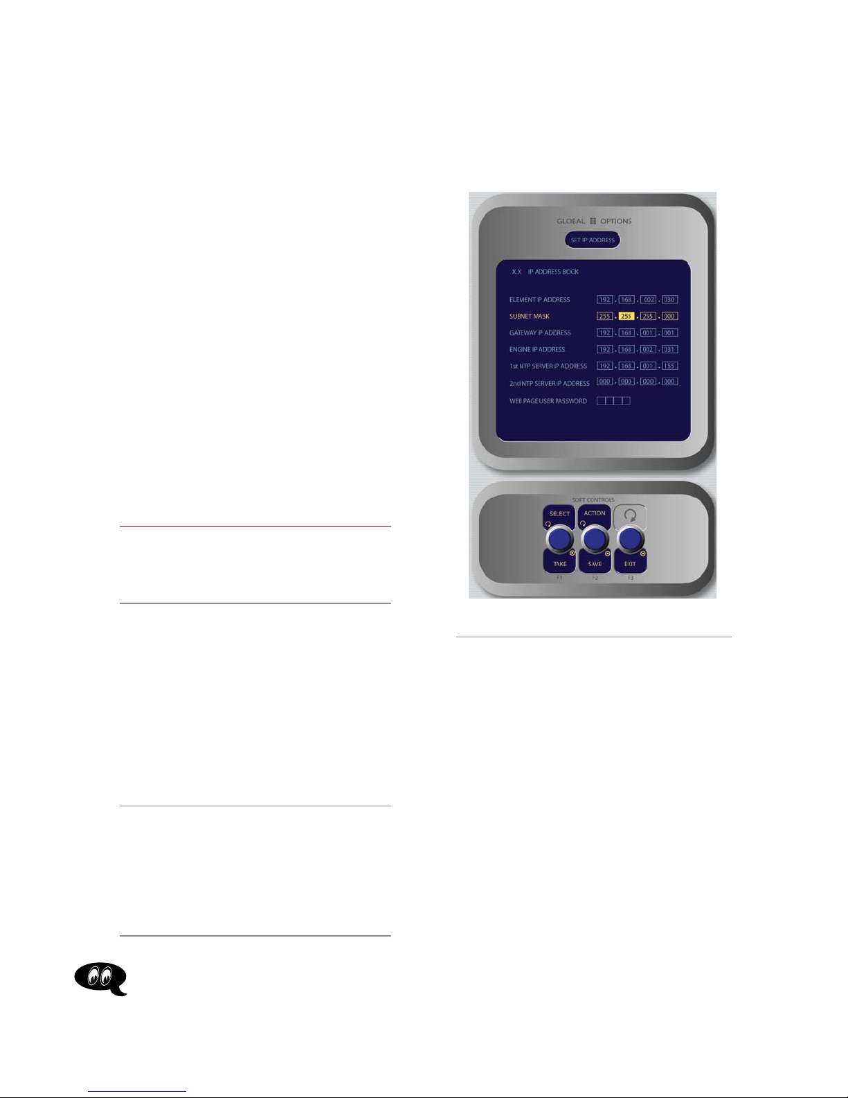
initialized. To do this, you’ll need to enter Capture Mode.
The way you’ll do this depends on whether the standard
Monitor Module or the Monitor + 2-Fader Module is in-
stalled in your Element.
Figure 1- 4: Detail of data/communication cable ends.
Connect a VGA monitor to the VGA connector on
4.
the back of the Element GPIO/Power Supply.
IMPORTANT: Element’s power cable is also
host to all data communication between the actual surface and its CPU (housed in the Element
Power Supply/GPIO Node) by CANbus technology; it does not require a separate Ethernet
connection. Never connect any of the RJ-45
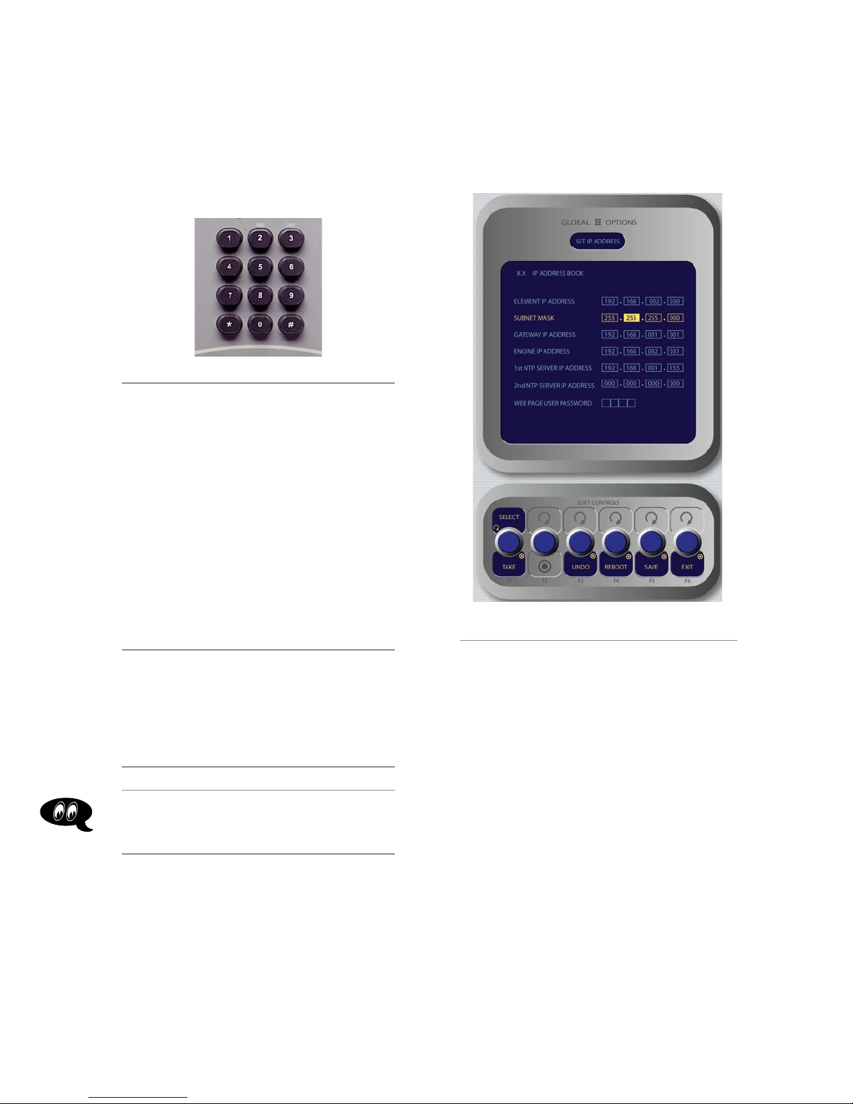
Figure 1-5: Element connection panel. Circled
connector is for power/data cable; RJ-45’s connect to
fader and accessory modules.
Figure 1- 6: Identifying the Standard Monitor Module
(left) and Monitor + 2-Fader Module (right).
“Capturing” using the Standard Monitor Module
Press and hold the Help key on the Monitor Module
for 5 seconds. The alphanumeric displays will change
1: Setup & Connections • 3
©2008 Axia Audio — Rev. 3.0
Page 14
to read Capture Mode; this enumerates all of the in-
stalled faders in the control surface.
Now, make sure that LED displays above the faders
display the channel numbers in the order you desire. If
not, you can adjust them individually using the PGM1
and PGM2 buttons above each fader to change the chan-
nel number to the one you desire. Note that even though
the hardware will let you assign channel numbers as
high as 64, numbers greater than 28 should not be used.
When you’re done adjusting displays, press the 8
(enter) key to exit Capture Mode. Your Element is
ready to use.
“Capturing” using the Monitor + 2-Fader Module
Press and hold both the * (star) and “2” keys on the
Monitor Module numeric pad for 5 seconds. The alpha-
numeric displays will change to read Capture Mode;
this enumerates all of the installed faders in the control
surface.
Now, make sure that LED displays above the faders
display the channel numbers in the order you desire. If
not, you can adjust them individually using the PGM1
and PGM2 buttons above each fader to change the chan-
nel number to the one you desire. Note that even though
the hardware will let you assign channel numbers as
high as 64, numbers greater than 28 should not be used.
indicator. Pressing the fader’s PGM1 and PGM2
keys will change the numeric indicator, indicating
the “Master” to which this fader is now slaved; a
display reading 2’ means that the fader is slaved
to fader 2.
Pressing the Options key again returns the fader to non-mirrored mode.
Short Navigation Tutorial
There are several different ways to change on-screen
options. The first way is with Element’s SoftKnobs, lo-
cated directly above the Monitor Module and shown in
Figure 1-7.
Figure 1-7: Element SoftKnobs.
These knobs are context-sensitive. When any of Ele-
ment’s setup modes are activated using the options keys
on the faders or Master Module, you’ll see a correspond-
ing row of “knobs” represented onscreen, as shown in
Figure 1-8.
When you’re done adjusting displays, press the #
(pound) key to exit Capture Mode. Your Element is
ready to use.
Hello Moto: If you have motorized faders, you
can “mirror” other motorized faders while you
are in Capture Mode. A motorized fader that is
“slaved” to a master fader will move automati-
cally to mirror the movements of the master.
Mirrored faders both control gain for the same
source, but the master can override the setting
of the slave — useful for “split” Element setups
where talent has a local set of faders that may
be used to control cer tain sources, but you still
want the Board Operator to have master control.
To mirror a fader, press the Options key above
the fader you wish to make the “slave”. An apostrophe (‘) will be displayed next to its numeric
1: Setup & Connections • 4
Figure 1-8: On-screen SoftKnobs.
Note that there are sometimes functions shown both
above and below the on-screen SoftKnobs. When a func-
tion is presented above the knob, turning that knob ac-
complishes that function. When a function is presented
below the knob, pushing in gently on the corresponding
SoftKnob activates that function. The example shown in
Figure 1-8 is from the IP Address Book screen.
If your Element is equipped with the standard Moni-
tor Module, you can also navigate using the control knob,
directional keys and Enter key located at the lower right-
hand corner of the module, as shown in Figure 1-9.
©2008 Axia Audio — Rev. 3.0
Page 15
Additionally, whenever numeric input is required
(like entering IP addresses), you can use the numeric
keypad located just above the Navigation Keys (Figure
1-10) to enter numbers directly.
Figure 1-10: Master Module numeric keypad.
IP Address Conguration
Using your IP Assignment Worksheet, you’ll
now choose an IP address for both your Element and
StudioEngine. You must make sure that IP addresses
for both Engine and Surface are in the same IP network,
and are both valid Unicast addresses. For example:
tions on the Monitor Module. Press and hold the key
marked Fader Options located in the top right corner
of the module for five seconds to enter the IP Address
Book (Figure 1-11).
192.168.2.101: Engine
»
192.168.2.201: Surface
»
Both addresses belong to 192.168.2.x IP network,
and so will work for our application.
Note: “Gateway” settings on Livewire equipment are optional. They may be lef t blank unless you intend to access the StudioEngine’s
conguration utility remotely, from outside your
network. Should you desire to do so, enter the
IP address of your master router (the one with
external network connections) whenever you’re
given the option to enter a gateway IP address.
Note: Element v2.x software supports redun-
dant NTP servers. Use the second eld in the IP
Address Book to enter the address of a backup
server.
Once you’ve determined the IP addresses you’ll as-
sign, turn on the Element power supply and the attached
VGA monitor.
Setting IP using the Standard Monitor Module
When Element has completed its start cycle (meter
screen appears), find the section marked Global Op-
Figure 1-11: IP Address Book,
Standar d Monitor Module
To set the IP address, rotate the leftmost SoftKnob to
highlight the line titled “Element IP Address” and push
the knob to select that line. Now use the numeric pad to
enter the IP address. Press the leftmost SoftKey again
to “take” the new IP value. Repeat this process to set the
subnet mask value.
Continue down the screen and, in the same way, en-
ter the other fields’ values as appropriate.
Rotate the Select/Set SoftKnob to scroll through
•
the list of available options. To select an option to
modify, push this knob. While modifying an options,
rotate the knob to change an option’s value, and push
the knob to move to the next field. Available options
include:
Element IP Address: Every piece of Livewire
»
gear must have its own unique IP Address. Set
the IP Address for each Element in this field.
1: Setup & Connections • 5
©2008 Axia Audio — Rev. 3.0
Page 16
Subnet Mask: Enter your network’s subnet
»
mask value here, usually 255.255.255.0
Gateway IP Address: To enable remote admin-
»
stration of your Livewire network, you’ll need a
network gateway. If you have one installed, enter
its IP Address value here.
Engine IP Address: Each Axia control surface
»
controls a unique Studio Engine. Enter the IP of
the controlled Engine here.
1st NTP Server IP Address: Element supports
»
NTP (Network Time Protocol) timekeeping to
synchronize time-of-day clocks across your fa-
cility. If you have an NTP server, enter its IP Ad-
dress here.
2nd NTP Server IP Address: Element v2.x
»
software supports redundant NTP servers. Enter
the IP Address of your backup server here.
Web Page User Password: You can password-
»
protect your Element’s webserver connection by
entering a numeric password here.
(meter screen appears), find the numeric keypad at the
top right of the Monitor Module. Press and hold the *
(star), “7” & “4” keys simultaneously for five seconds
to enter the IP Address Book (Figure 1-12).
1: Setup & Connections • 6
Note: If you set a password for HTTP access,
you will not see your password displayed in this
eld upon re-entering the IP Address book. This
is a security feature intended to prevent “overthe-shoulder” password thef t.
If you want to reverse changes you’ve made and haven’t
•
saved, press the Undo knob to erase them.
Press Reboot to immediately reboot the Element.
•
Press Save to save changes you’ve made.
•
Press Exit to leave the IP Address Book.
•
Note: After making changes to any Element IP
address settings, you must reboot the console.
Use the “REBOOT” soft key to begin an immediate
reboot sequence.
Remember, you can even reboot Element while
on-the-air, since the audio mixing is not done in
the console but in the Studio Engine; your audio
will continue to play without interruption.
Setting IP using the Monitor+ 2-Fader Module
When Element has completed its start cycle
Figure 1-12: IP Address Book,
Monitor Module
To set the IP address, rotate the leftmost SoftKnob to
highlight the line titled “Element IP Address” and push
the knob to select that line. Now use the numeric pad to
enter the IP address. Press the leftmost SoftKey again
to “take” the new IP value. Repeat this process to set the
subnet mask value.
Continue down the screen and, in the same way, en-
ter the other fields’ values as appropriate.
Rotate the Select/Set SoftKnob to scroll through
•
the list of available options. To select an option to
modify, push this knob. While modifying an options,
rotate the knob to change an option’s value, and push
the knob to move to the next field. Available options
include:
Element IP Address: Every piece of Livewire
»
gear must have its own unique IP Address. Set
the IP Address for each Element in this field.
©2008 Axia Audio — Rev. 3.0
Page 17
Subnet Mask: Enter your network’s subnet
»
mask value here, usually 255.255.255.0
Gateway IP Address: To enable remote admin-
»
stration of your Livewire network, you’ll need a
network gateway. If you have one installed, enter
its IP Address value here.
Engine IP Address: Each Axia control surface
»
controls a unique Studio Engine. Enter the IP of
the controlled Engine here.
1st NTP Server IP Address: Element supports
»
NTP (Network Time Protocol) timekeeping to
synchronize time-of-day clocks across your fa-
cility. If you have an NTP server, enter its IP Ad-
dress here.
2nd NTP Server IP Address: Element v2.x
»
software supports redundant NTP servers. Enter
the IP Address of your backup server here.
Web Page User Password: You can password-
»
protect your Element’s webserver connection by
entering a numeric password here.
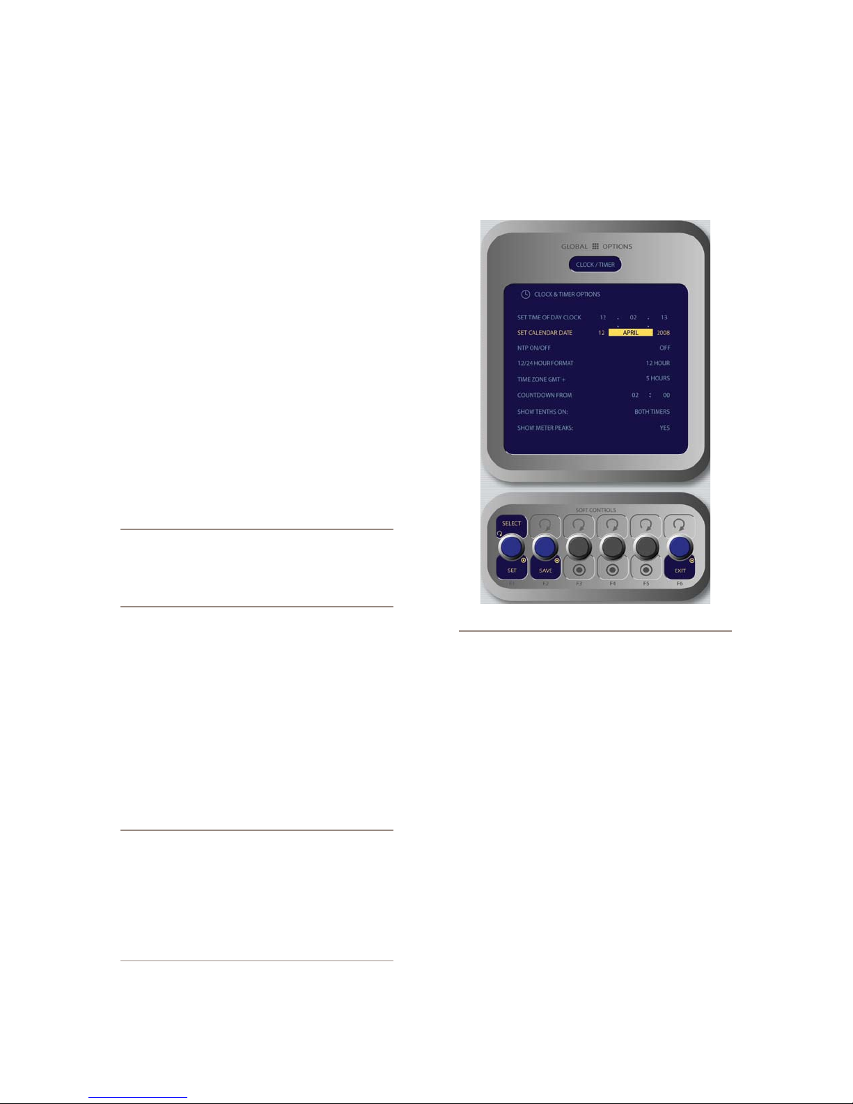
Clock Conguration
Locate the Timer section of the Monitor Module;
press and hold the key marked Options to enter the
Clock & Timer Options screen (Figure 1-13).
Note: If you set a password for HTTP access,
you will not see your password displayed in this
eld upon re-entering the IP Address book. This
is a security feature intended to prevent “overthe-shoulder” password thef t.
Rotating the Action knob choosees between the fol-
•
lowing options:
Save stores the changes you’ve made to the IP
»
Address Book.
Undo reverses any changes you’ve made if you
»
haven’t yet saved them.
Reboot immediately reboots the Element.
»
Press the Exit knob to leave the IP Address Book.
•
Note: After making changes to any Element IP
address settings, you must reboot the console.
Use the “REBOOT” soft key to begin an immediate
reboot sequence.
Remember, you can even reboot Element while
on-the-air, since the audio mixing is not done in
the console but in the Studio Engine; your audio
will continue to play without interruption.
Figure 1-13: Clock & Timer Options menu screen.
Rotate the Select/Set SoftKnob to scroll through
•
the list of available options. To select an option to
modify, push this knob. Rotate the knob to change an
option’s value, and push the knob when you’re done
to move to other fields. Available options include:
Set Time Of Day Clock: If you do not have an
»
NTP (Network Time Protocol) server configured
as part of your Livewire IP-Audio network, use
this option to set the correct time for Element’s
on-screen clock.
Set Calendar Date: Choose this option to set
»
Element’s on-screen calendar.
NTP On/Off: If you have an NTP server tied to
»
your IP-Audio network, set this option On. If you
do not, or if your NTP server is supplying incor-
rect time data, turn this option Off to keep time
with Element’s internal clock.
12/24-Hour Format: This option switches the
»
1: Setup & Connections • 7
©2008 Axia Audio — Rev. 3.0
Page 18
on-screen time display between 12-hour (normal-
style) and 24-hour (military-style) timekeeping.
Time Zone GMT+: Use this field to set the glob-
»
al time zone your station is located in, relative to
Greenwich Mean Time.
Push the Save knob to commit to the changes you’ve
•
made. You may do this at any time, after changing
any option to apply the change immediately.
Push the Exit knob to leave the Clock & Timer Op-
•
tions screen.
Time And A Word: The term “Greenwich Mean
Time” refers to Britain’s Royal Greenwich Obser-
vatory, which lies athwart the Prime Meridian.
Time at this location is referred to as “base time,”
to which all other time zones are relative. GMT is
properly referred to as UTC - “Coordinated Universal Time.”
If you’re at a loss as to what the GMT offset is
for your location, a complete list is located online at www.wikipedia.org . Enter a search for
“Time Zone” and scroll down the resulting page.
Countdown From: When the operator enters an
»
interval of time into this field, Element’s count-
down timer will count backwards from this num-
ber to zero upon exit of this screen.
Show Tenths On: Allows you to set the count-
»
down and elapsed-time counters to show or hide
tenths-of-a-second displays.
A Note About Metering: Element’s bargraph
meters feature true VU meter ballistics, though
with an expanded scale. The red line at -20dBFS
corresponds to the 0dB mark on a traditional
analog meter. Just as with a traditional analog
meter, the 300ms time-constant lter specied in the VU standard means that peaks are
much higher than the meter indicates. Depending upon the nature of the program material,
transient peaks will be 9-15dB higher than the
VU-ltered average. This is why modern consoles, including Element, have 20dB headroom
above the nominal operating level. Some of this
headroom is used to cover the peak transients
the VU meter can’t see, and some is used for
operator error or surprise margin. (ie, the wellknown “excited sportscaster scream”.)
By default, Element meters are set to display
both average and peak levels, the average being represented by the main bargraph display,
and the peaks represented by the small oating
line that appears above them.
The next section will walk you through setting up
your StudioEngine.
StudioEngine Quick Setup
Connections and IP Conguration
Connections
Note: We recommend leaving 1RU of “breath-
ing space” for ventilation above and below the
StudioEngine when you rack-mount the unit.
Using the supplied AC power cord, connect the
StudioEngine to the mains. Route a length of CAT- 6 ca-
ble from StudioEngine to a Gigabit port on your studio’s
Ethernet switch, but don’t connect it yet.
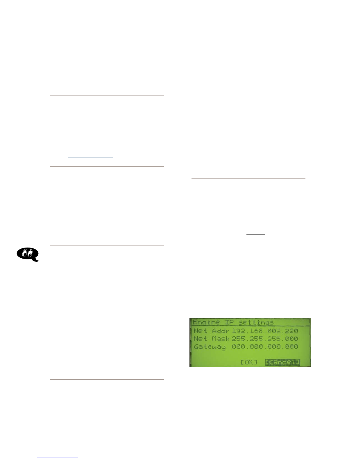
IP Conguration
Power on your StudioEngine; the front-panel display
1.
will indicate the boot-up sequence. When the screen
displays IP address and network connection informa-
tion, push the control knob to call the Main Menu.
Turn the control knob to highlight Option #4, IP
2.
Settings (Figure 1-14), and push to select.
Figure 1-14: StudioEngine IP conguration screen.
Show Meter Peaks: Allows you to turn Ele-
»
ment’s Peak meter display on or off. Yes dis-
plays peaks; No does not.
1: Setup & Connections • 8
Push the control knob and you’ll see that the first
3.
line of the display (marked Net Addr) is underlined.
Push the knob again to select this line.
You’ll see a flashing underline under the first digit
4.
©2008 Axia Audio — Rev. 3.0
Page 19
of the IP address. Push and rotate the control knob
to select the value for this digit. Push again to “take”
the value.
Continue this sequence until your IP address is prop-
5.
erly entered. When finished, turn the control knob
until the check mark at the end of the line is high-
lighted, and push the knob to apply the new IP ad-
dress value.
When you’ve set the subnet mask and gateway IP ad-
6.
dress, choose OK at the bottom of the screen.
You’ll be asked if you’d like to reboot for changes
7.
to take effect. select YES and connect the Ethernet
cable to your StudioEngine.
Secret Button Function: Here it is, the rst
of many “secret” controls hidden about Element and meant for your Engineering eyes only.
If, during bootup, you press the StudioEngine’s
control knob within 6 secs of the initial screen
display, you’ll be asked if you want to reset the
front panel and HT TP passwords to factor y default. This is your “backdoor” into the system
should you forget the login password to the
front panel. Changing these passwords forces
a reboot.
devices generate? Think about how many audio sources
and destinations there are in even a small studio — there
are a lot to keep track of. In the analog days, we’d affix
a numbered label to each cable that entered the terminal
room to identify each audio circuit. Obviously, we can’t
attach pieces of paper to digital packet streams, but we
can give each one a “label.”
We refer to these “labels” as Network Channel Num-
bers. Each Livewire system can support 32,766 channels
of audio, which enables us to give each audio source or
destination its own unique numeric channel number.
Note: 32,000+ channel numbers exceeds the
average human’s RAM storage capacity. We recommend using a spreadsheet program — just
to make sure you don’t generate painful readmemory register errors.
As soon as you connected your StudioEngine to the
network (following the steps in the previous section), it
began to generate audio using factory default channel
numbers. To avoid conflict with other studios, you must
change those default values to new channel numbers.
StudioEngine Channel Settings
For the next steps we’ll be using the StudioEngine’s
HTTP interface, so connect a computer loaded with
an Internet browser to the local switch. This computer
should have an IP address in the same range assigned to
the Element and StudioEngine.
Note: Axia web interfaces have been tested
with Microsoft Internet Explorer, version 5 or
later, but may also work with other browsers.
Whatever browser you choose, Java must be
enabled and your pop-up blocker, if any,
must be disabled in order to work with A xia
equipment.
Note that Windows Vista versions do not have
Java installed by default as in prior versions.
You must install the Sun Java package found at
http://www.java.com .
In a Livewire network, individual devices (audio
nodes, studio controllers, etc.) are identified by unique
IP addresses. But what about the audio streams these
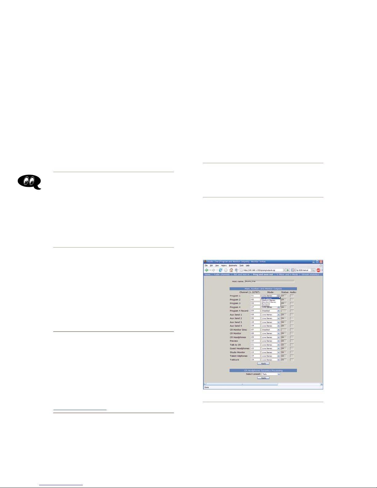
Figure 1-13: StudioEngine Output conguration
Open the browser on your computer and point it to the
1.
IP address you previously set for your StudioEngine.
Choose the Program And Monitor Outputs menu
option to configure the output buses of the Element.
1: Setup & Connections • 9
©2008 Axia Audio — Rev. 3.0
Page 20
You’ll be prompted to enter a user name and pass-
2.
word. The default user name is “user”. Leave the
password field blank.
You’ll see the screen shown in Figure 1-13, This
3.
screen allows you to set channel numbers for all of
the audio outputs generated by Element; program
and record busses, monitor feeds, and talkback
destinations. Work down the list, assign each one
a unique channel number and record them in your
channel number log.
Find the column entitled Mode. Each Studio Engine
4.
is shipped with the most common streams enabled
with Live Stereo mode. Make sure all of your de-
sired streams are enabled.
Choose Apply.
5.
A word about stream types: There are
several different types of streams available in the Mode dropdown box: Live Ste-
reo, Medium Stereo, Standard Stereo
and Surround.
Live Stereo was previously referred to as
Livestreams. Use Live Stereo streams when-
ever you need the lowest latency for on-air
feeds, mic-to-headphone paths, etc.
Medium Stereo is our recommended default
for everything else. This setting balances low
latency with high compatibility for systems containing PC playout systems.
Standard Stereo
best
compatiblity with older PC systems, but
the tradeoff is that these streams have a higher
amount of latency.
Surround Streams: Element can mix both Stereo and Surround (5.1) audio. If you’re feeding
the system with a 5.1 audio source, choose the
Surround option.
is intended to provide the
Note: Manual setting of console type is only
necessary on Element consoles running software versions prior to v2.0. In Elements running
v2.0 or higher, this setting will auto-detect.
Advanced Settings
You’ve no doubt noticed that there are many more
options for your Element and StudioEngine than we’ve
covered here. That’s because Chapter One was meant to
get you up and running as quickly as possible. For
depth explanation of the other available settings,
an in-
please
refer to Chapters 7 & 8 of this manual.
What’s Next
Take a break! You’re done with initial set-up. When
you’re ready, continue to the next chapter to walk
through one of the most important Element concepts:
Source Profiles. q
Set Your Console Type
Axia StudioEngines will work with different types of
consoles, so you need to tell it which type you’re pairing
it with.
Navigate to the “Engine ID” menu and find the “Ap-
1.
plication Interface Options” section. Be sure that
Element
Click
2.
is checked for the “Console Type”.
Apply
.
1: Setup & Connections • 10
©2008 Axia Audio — Rev. 3.0
Page 21

Chapter Two:
Configuring Inputs
In this chapter we’ll discuss how to set up inputs for
your Element. You’ll be using the HTTP servers built
into the Element and StudioEngine to do this.
Note: Axia web interfaces have been tested with
Microsoft Internet Explorer, version 5 or later,
but also work with other browsers.
We also like Mozilla’s FireFox browser, especially
with regards to its “tabbed browsing” capabilities. With tabbed browsing, it’s possible to bookmark the IP addressees of entire rooms worth of
Audio Nodes, then recall them in tabbed groups
with a single click.
Whatever browser you choose, Java must be
installed and enabled, and your pop-up blocker
must be disabled. The latest Java package is
available at http://www.java.com .
Understanding Source Profiles
One of the most repetitive and tedious parts of studio
building has always been tying “data” to audio sources.
Consider the wiring of line selector modules: you need
a cable for the remote audio source, a set of wires for a
“start” closure, another set for “stop” — even with TDM
routers, an operation as seemingly simple as logic-fol-
lows-audio often turns out to be not so simple.
Element Source Profiles allow you to assign modi-
fiers to an audio input. Characteristics like EQ curves,
Pan trim, voice dynamics, even mix-minus source selec-
tions, can all be set in the Source Profile and are then
automatically loaded whenever that source is assigned
to an Element fader.
The result of all this is that Element is always pre-
sented with complete, consistent information about how
you want a given audio source handled.
Note: Source Prole settings do not transfer
between studios. In other words, a mic in Studio A that has EQ and dynamics applied through
a Source Prole on the Studio A Element will
not have those settings automatically applied if
that mic is loaded on the Element in Studio B.
We are, however, planning on this capability in
future versions.
Source Profile Setup
Now that you understand what Source Profiles do,
let’s set one up. You’ll use the Element and StudioEngine
HTTP interfaces to do this, so connect a computer with
an Internet browser to the local switch.
Note: You can’t construct Source Proles unless you’ve already congured the inputs and
outputs of your studio’s Audio Nodes. Be sure
you’ve assigned Livewire channel numbers and
enabled all sources in your Nodes, Engine, and
PC drivers. This will make your sources visible
on the selection list in the source prole setup
screen. Make sure you’ve done this before proceeding further through this chapter.
Mix-minus and IFB generation is also a problem.
Too often it’s a complicated process that requires air tal-
ent to correctly determine source and bus assignments at
a moment’s notice. How many times has unwanted audio
made air thanks to this error-prone procedure?
Element eliminates these headaches by letting you
merge audio, logic and program data into a single,
routable information stream. Since audio in a Livewire
network is transported as packetized data, it’s easy for
us to “piggyback” other data along with audio. This is
accomplished through the use of Source Profiles.
Your computer must be assigned a valid network IP
address in order to “see” Livewire web pages. Livewire
networks do not contain DHCP servers, so you must
manually assign your computer an IP address within
the range you previously determined for your network.
Different operating systems use different methods to do
this; please consult your OS’s documentation for spe-
cific instructions.
Source Prole Options
Enter the IP address of your Element in your browser;
1.
©2008 Axia Audio — Rev. 3.0
2: Conguring Inputs • 11
Page 22

2: Conguring Inputs • 12
you’ll see the “Element Control Center” displayed
onscreen. Using the sidebar menu, choose the “Con-
figuration” menu item under the “Sources & Profiles”
heading. Enter your password in the box (default is
“user”) and click OK.
Choose the Source proles menu item from the
2.
main screen, and click the New Source Prole link
at the bottom of the screen. You’re now in the Source
Profile creation screen.
Reminder: Did you dene your audio sources
from the Engine and Nodes as outlined in Chapter One? If not, go no further – you’ve got to do
that before you can continue with Source Prole
setup.
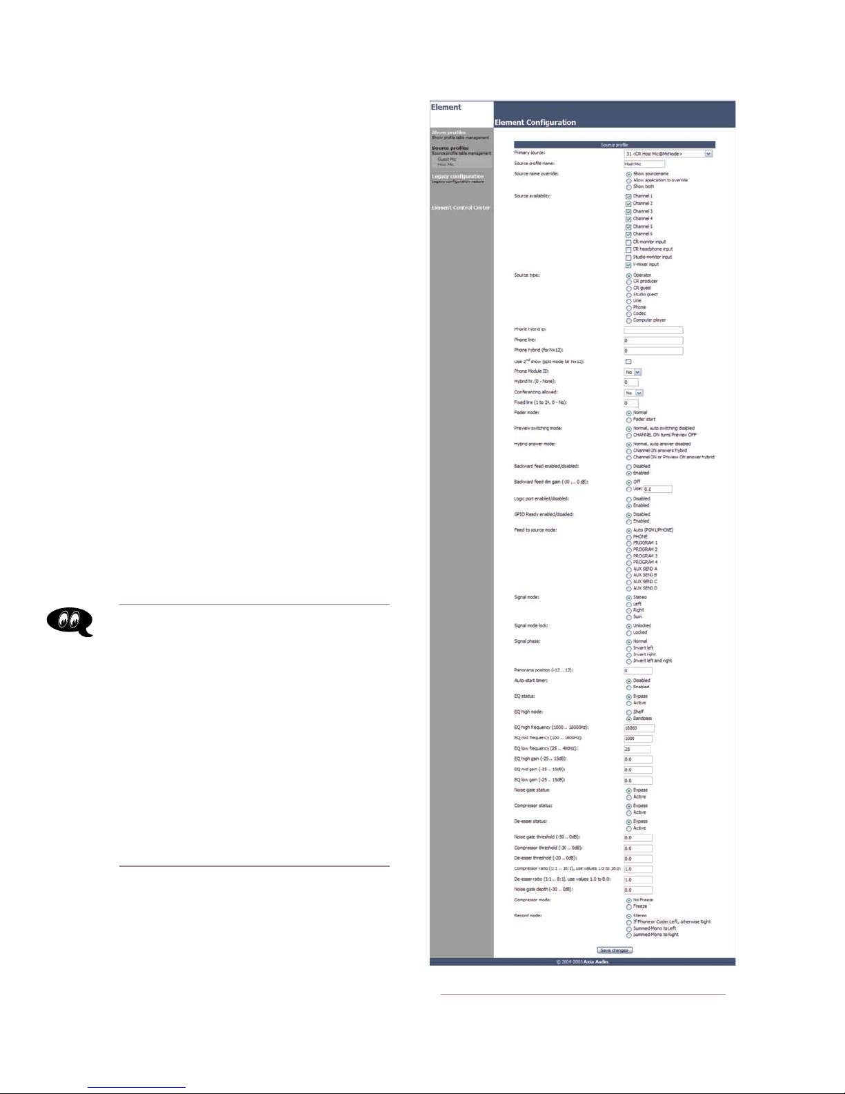
PRIMARY SOURCE: All of the audio sources that
•
you previously defined (during Audio Node setup)
are available in this drop-down box; pick one.
SOURCE PROFILE NAME: Type a 10-character de-
•
scriptive name for your source.
SOURCE NAME OVERRIDE: If the source you’re
•
defining can supply Program Associated Data (for
instance, a computer playout system that sends song/
artist information), you can choose to have that text
dynamically substituted in the alphanumeric dis-
play of the fader the source is assigned to. Instead
of reading PROPHET_1, for example, it could scroll
FERGIE.
Choose Show Sourcename to have the channel
»
alpha display the name you typed into the Source
Profile Name field above.
Choose Allow Application to Override if you’d
»
like the PAD text displayed instead.
Choose Show Both to scroll the Source Name
»
followed by the PAD text across the alpha dis-
play.
SOURCE AVAILABILITY: These check boxes de-
•
termine which faders (or other inputs) you’ll allow
this source to be assigned to. For example, if your
source is a Control Room mic, and you only want
it to appear on the left-most fader, you would check
only the box marked Channel 1. You might want to
make a CD player available on any fader, so you’d
check the boxes for all faders. Some sources – es-
pecially air monitors – you might wish to prevent
from ever being assigned to a fader, so you would
uncheck the boxes for all faders. The number of fad-
er checkboxes show will vary depending upon the
number of faders installed in your Element.
The four final check boxes, CR monitor input, CR
headphone input, Studio monitor input and V-
Mixer input determine whether the board op will
be able to assign this source to the monitor and head-
phone buses or the Virtual Mixer (please see Chapter
6: Virtual Mixer for details on this feature).
To prevent a source from appearing on these inputs’
selection lists, uncheck the desired box.
About Mics and Headphone Feeds: Element
provides you with several headphone options,
all selectable from Element’s Monitor Module. The Monitor 1 (control room) headphone
output provides a feed intended for the Host
(board-op’s) mic position and includes the ability to monitor the Preview bus in headphones.
Guests can talk to the host directly using the
Talkback keys on their remote control panels.
The Monitor 2 headphone output sends au-
dio to talent and guest mic positions. Talent
positions include a talkback channel that the
host or board op can use to communicate using the Talk To Monitor 2 function (guest
positions do not have this Talkback channel).
An individual headphone feed can also be constructed to associate a dedicated headphone
channel with a specic mic. This allows the
board op to send individual, targeted talkback
to a specic individual (using the Talkback
keys) without other talent or guests hearing.
SOURCE TYPE: Define your source as a micro-
•
phone, a line input, a telephone input, a codec or a
computer source.
Operator is the board operator’s mic. It is the
»
source mic for Element’s TALK TO functions. Its
On button serves as a COUGH/MUTE button. Its
associated logic mutes the CR monitors when
On.
CR Producer is used for in-studio Producer’s
»
mic positions. It has associated GPIO logic
©2008 Axia Audio — Rev. 3.0
Page 23
which can operate Talk to... functions from a
remote producer’s panel. It also mutes CR moni-
tors when On.
CR Guest is used for any other guest mic in the
»
control room. Its associated logic port mutes the
CR monitors when On. It can have an individual
headphone feed.
Studio Guest is used for any mic located in a
»
separate studio. Its logic mutes the Studio moni-
tors when On. It can have an individual head-
phone feed.
Line is used for any line input audio source, ana-
»
log or digital. A GPIO logic port can be used to
provide machine start/stop pulses if desired.
Phone defines this source as a hybrid or broad-
»
cast phone system input. Summed mono mix-mi-
nus provided.
Codec marks this source as a codec. Dual-mono
»
mix-minus provided; one PA feed + one talent
feed with talkback.
Computer Player defines this source as origi-
»
nating from a PC. Associated GPIO logic can be
used to send start/stop signals to a playout sys-
tem.
About Telos Phone System Modes: Telos
TWOx12, Nx12 and Series 2101 broadast phone
systems work in two different modes: US Mode
and Euro Mode.
In US Mode, one of the phone system’s hybrids is assigned to a console faders, and taking a caller to air is accomplished by using a
switching control to select a line on that hybrid
and turning its fader ON.
In Euro Mode, the swiching control is not used;
instead, each line from the phone system is permanently assigned to a separate fader, which
may be turned ON or OFF at will.
Element supports both US and Euro modes. The
next few settings are used for setting up the
desired style of phone operation.
The next 4 options are used for EURO mode only:
PHONE HYBRID IP: If this source is a Telos Nx12,
•
TWOx12, Series 2101 or Telos TWO and you will be
operating in Euro mode, enter the IP address of the
phone system.
Figure 2-1: Source Prole options (yes, there are a lot!)
2: Conguring Inputs • 13
©2008 Axia Audio — Rev. 3.0
Page 24
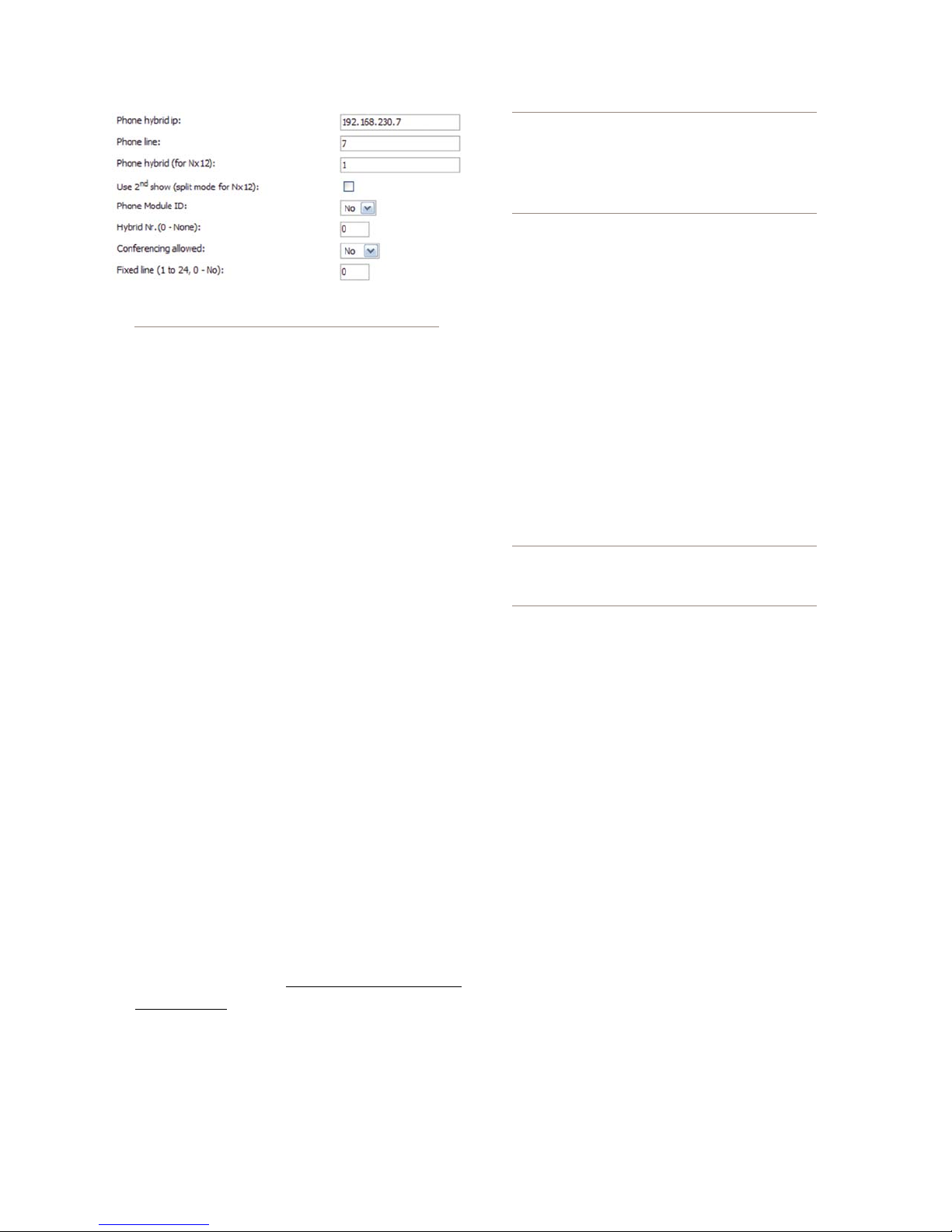
Figure 2-2: Set tings for conguring Element for
operation with Telos phone systems
Nx12 Users Note: For Nx12’s second show,
you would STILL enter “1” for Hybrid 3 and “2”
for Hybrid 4. Why? Because, to Nx12’s internal
logic table, Hybrid 3 is really the rst hybrid in
Show 2 and Hybrid 4 is the second hybrid in
Show 2.
CONFERENCING ALLOWED: For Telos Nx12,
•
TWOx12 or Series 2101 operating in US mode. Spec-
ifies whether or not “button mash” conferencing is
permitted. Select Yes to allow, No to prohibit.
2: Conguring Inputs • 14
PHONE LINE: If this source is a Telos Nx12,
•
TWOx12, Series 2101 or Telos TWO and you will
be operating in Euro mode and wish to dedicate a
phone line to this fader, enter it here.
PHONE HYBRID (FOR NX12): Even though the
•
option title says “for Nx12”, if this source is a Telos
Nx12, TWOx12 or Series 2101 and you will be oper-
ating in Euro mode, you may specify hybrid 1 - 4 for
this line assignment.
USE 2ND SHOW (SPLIT MODE FOR NX12): Even
•
though the option title says “for Nx12”, if this source
is a Telos Nx12, TWOx12 or Series 2101 and you
will be operating in Euro mode, you may check this
to designate Split Studio Mode, where two hybrids
are assigned to one show, and the other 2 assigned to
a second show. Element will connect to the second
Show in the list.
The next 4 options are used for US mode only:
PHONE MODULE ID: For Telos Nx12, TWOx12 or
•
Series 2101 operating in US mode. If you are con-
structing a Source Profile for a telephone hybrid and
have multiple Phone Modules installed, this allows
you to determine which module will control this hy-
brid. For details on setting up a phone system with
Element, please refer to Appendix D: Working With
Phone Hybrids.
HYBRID NR.: For Telos Nx12, TWOx12 or Series
•
2101 operating in US mode. Specify which hybrid
this Source Profile will control.
FIXED LINE: For Telos Nx12, TWOx12 or Series
•
2101 operating in US mode. When working with a
Telos hybrid that supports it, this command lets you
assign a line permanently to a specific fader, emulat-
ing a dedicated hybrid.
0 means there is no fixed line assigned.
»
1 - 24 slaves the specific line to this source’s
»
fader.
Note: For complete instructions on set ting up a
phone system with Element, please refer to Ap-
pendix D: Working With Phone Hybrids.
FADER MODE: Allows you to set the channel activa-
•
tion method of the fader this source is assigned to.
Normal conforms to the US method of requiring
»
talent to manually turn the channel on and off.
Fader Start follows the common European
»
standard of activating the channel and associated
machine logic when the fader is raised from ∞.
PREVIEW SWITCHING MODE: Determines what
•
will happen to a source’s off-air Preview assign-
ment when that source is taken to air.
Normal, Auto-Switching Disabled: The Pre-
»
view bus assignment will be retained even after
the fader is turned ON.
CHANNEL ON turns Preview OFF: If this
»
source is assigned to Preview for off-air audi-
tioning, turning its channel ON will cancel its
Preview assignment.
HYBRID ANSWER MODE: This setting allows you
•
to tailor Element’s Hybrid Answer mode to suit your
facility’s operating style.
©2008 Axia Audio — Rev. 3.0
Page 25

Normal, Auto Answer Disabled: SmartSurface
»
provides no auto-answer logic when a fader with
a hybrid assigned is turned On.
Channel ON Answers Hybrid: When a hybrid
»
has an incoming call, turning its assigned fader
ON will answer the call.
Channel ON or Preview ON Answers Hybrid:
»
When a hybrid has an incoming call, turning its
assigned fader ON or pressing that channel’s
Preview key will answer the call.
BACKWARD FEED ENABLED/DISABLED: Al-
•
lows you to enable or disable backfeeds to this audio
source.
BACKWARD FEED DIM GAIN: This is a feature
•
unique to Element: Talkback is sent over dimmed
backfeed audio. If you want a hard interruption
(Talkback interrupts Program audio), set it to maxi-
mum dim, which mutes the audio. But maybe your
jocks would like to just have their program audio
dimmed, and the Talkback come over it so they can
still monitor air while they’re being talked to. In this
case, input a value by which the program audio will
be dimmed. Adjustment range is 0dB to -30dB.
LOGIC PORT ENABLED/DISABLED: Allows you
•
to enable or disable GPIO machine logic to this au-
dio source device.
GPIO READY ENABLED/DISABLED: Allows de-
•
vices such as CD players or tape machines to sig-
nal their readiness to the operator through the OFF
button LED. If a device is cueing, its STOP lamp
will not be lit. Tying the device’s stop lamp to the
Ready command means that a machine must be cued
and ready before the OFF lamp illuminates.
If Enabled, the OFF lamp illuminates only when the
fader is OFF and the Ready command is active on
the GPIO. If Disabled, the OFF lamp illuminates
normally whenever the fader is turned OFF.
FEED TO SOURCE MODE: If there is a backfeed
•
associated with this source, this option determines
what content is fed back from the board.
Auto (Pgm-1/Phone) feeds the Program 1 bus
»
(minus the source) when this source’s fader is ON,
and feeds the Phone bus (minus the source) when
the fader is OFF. (Program 1 and 2 feeds are post-
fader; Phone feed is pre-fader to allow speaker-
phone style operation thru the Operator’s mic.
Phone feeds the Phone bus, minus the source.
»
PGM1 feeds the Program 1 bus, minus the
»
source.
PGM2 feeds the Program 2 bus, minus the
»
source.
PGM3 feeds the Program 3 bus, minus the
»
source.
PGM4 feeds the Program 4 bus, minus the
»
source.
AUX SEND A the Aux Send A bus, minus the
»
source.
AUX SEND B feeds the Aux Send B bus, minus
»
the source.
AUX SEND C feeds the Aux Send C bus, minus
»
the source.
AUX SEND D feeds the Aux Send D bus, minus
»
the source.
About the PHONE, RECORD and PROGRAM
4 buses:
cial multi-purpose bus that does several things
at once to make life easier for the operator.
Sources assigned to PGM-4 are also sent to the
RECORD bus, a special post-fader, pre-on/off
output that can be used to feed recording devices.
At the same time, sources assigned to PGM-4
are mixed and sent to the PHONE bus. PHONE is
an internal bus which does not feed a separate
output; instead, it picks up PGM-4 audio prefader and pre-On/Off and backfeeds it callers
(minus themselves, of course) when the channel
is OFF and AUTO is selected as the Feed To
Source Mode.
SIGNAL MODE: Determines whether source will be
•
Element ’s PGM-4 mix bus is a spe-
treated as mono or stereo, and how.
Stereo feeds incoming L/R signal to left and
»
right channels of assigned bus(es).
Left feeds incoming left channel to both chan-
»
nels of assigned bus(es).
Right feeds incoming right channel to both chan-
»
nels of assigned bus(es).
2: Conguring Inputs • 15
©2008 Axia Audio — Rev. 3.0
Page 26

2: Conguring Inputs • 16
Sum creates L+R mono mix of incoming stereo
»
source and feeds it to both channels of assigned
bus(es).
SIGNAL MODE LOCK: Allows or disallows user’s
•
ability to change the source’s signal mode (as set
above) using controls on Element’s surface.
Unlocked allows the user to change modes if
»
needed.
Locked prevents changes to the signal mode.
»
SIGNAL PHASE: Allows for correction of out-of-
•
phase program material.
Normal assumes correct phase polarity of source
»
input material.
Invert left reverses phase on the left channel
»
input.
Invert right reverses phase on the right channel
»
input.
Invert left and right reverses phase on both
»
channel inputs.
PANORAMA POSITION: Lets you preset pan set-
•
tings for this input. Pan is variable in 25 steps, center
being 0, far left -12 and far right 12. This setting can
be adjusted on the fly by the operator.
AUTO-START TIMER: Determines whether the
•
event timer found in Element’s right-hand meter
display will reset to zero when this source’s fader is
turned on.
Disabled: timer will not reset when this source
»
is activated.
Enabled timer resets when the source is acti-
»
vated.
About Element EQ: Equalization is available
for all audio sources, and can be pre-dened
or adjusted on-the-y. Our EQ model is three-
band quasi-parametric. Controls are provided
for center frequency and boost/cut, with a
unique SmartQ™ automatic bandwidth system.
SmartQ works by varying the Q of the selected
parametric band proportional to the amount of
boost or cut you specify. A small amount of boost
or cut will affect a broader range of frequencies
for a warm, musically-pleasing effect. As gain is
increased the Q sharpens, affecting a narrower
range of frequencies for tighter control of target
bands. At aggressive cut levels, the EQ becomes a
tunable notch lter. SmartQ keeps the EQ sounding natural at virtually all settings.
Pre-dened EQ can be entered during Source
Prole construction, and will be automati-
cally applied whenever that source is assigned
to a Element fader; i.e., a -2 dB 12 kHz high
shelf lter pre-set in a microphone’s Source
Prole will be applied when any sur face, in
any studio, loads that mic for use.
At-will EQ is set by talent using Element’s Chan-
nel Options controls, and can be employed to
trim EQ on-the-y .
•
EQ STATUS: Bypass or make Active EQ for this
source.
•
EQ HIGH MODE: Choose between shelf or band
pass filter for high-frequency EQ.
•
EQ HIGH FREQUENCY: Sets the active frequency
for high-band EQ. If EQ HIGH MODE is set to Shelf,
this setting determines the top of the shelf. If EQ
HIGH MODE is set to Band pass, this sets the cen-
ter frequency of the BP filter (SmartQ determines
the width of the BP filter, as described above).
•
EQ MID FREQUENCY: Sets the center frequency of
the midrange parametric band.
•
EQ LOW FREQUENCY: Sets the center frequency of
the low parametric band.
•
EQ HIGH, MID & LOW GAIN: Provides 40 dB of
adjustment range for boost or cut of the three para-
metric bands, from -25 dB to +15 dB.
The following options dealing with dynam-
ics processor settings apply to Mic, Codec and
Phone sources only. If applied to other source
types, these settings will be ignored.
•
NOISE GATE STATUS: Turns the voice processor’s
noise gate on and off. Choose Bypass or Active.
•
COMPRESSOR STATUS: Turns the voice proces-
sor’s compressor functions on and off. Choose By-
pass or Active.
©2008 Axia Audio — Rev. 3.0
Page 27

DE-ESSER STATUS: Turns the voice processor’s de-
•
esser module on and off. Choose Bypass or Active.
NOISE GATE THRESHOLD: Determines the point
•
at which the Noise Gate will operate (if set to Ac-
tive). Adjustment range is between 0dB and -50dB.
COMPRESSOR THRESHOLD: Determines the point
•
at which the Compressor will operate (if set to Ac-
tive). Adjustment range is between 0dB and -30dB.
DE-ESSER THRESHOLD: Determines the point at
•
which the De-Esser will operate (if set to Active).
Adjustment range is between 0dB and -20dB.
COMPRESSOR RATIO: Sets the amount of com-
•
pression that will be applied to the mic audio. Ad-
justment range is between 1:1 and 16:1.
DE-ESSER RATIO: Sets how aggressively the de-
•
esser will remove sibilance from the mic audio. Ad-
justment range is between 1:1 and 8:1.
NOISE GATE DEPTH: Sets the amount of noise
•
reduction that will be applied to the mic audio if
the noise gate is set to Active and the Noise Gate
Threshold is reached. Adjustment range is between
0dB and -30 dB.
COMPRESSOR MODE: Toggles the voice compres-
•
sor between Freeze and No Freeze modes.
What is this stuff? Radio engineers don’t need
a lesson in dynamics processing, but for the benet of any jocks reading this, here’s a quick explanation of what these controls can do.
A Gate is a dynamics device whose function
is to remove unwanted audio material below a
certain threshold. A gain circuit is employed to
raise or lower the volume of the audio signal;
when the signal falls below a certain set threshold, the audio level drops down to a predetermined level. The reason they are called gates
is because when they “close” it sounds as if
the audio has suddenly stopped, or has been
“gated.” You might use this on a mic channel to
eliminate background noise during times when
you’re not speaking.
Threshold settings determine at what level the
processor will begin working. For example, on
a compressor, when signal level exceeds the
threshold setting, it will be compressed; below
the threshold the signal will remain uncompressed. On a gate, threshold determines the
minimum input level required to cause the gate
to open up and pass signal; when input level
drops below the threshold, the gate will be closed
preventing signal from passing. Carefully setting
the threshold allows you to very specically control when processing is being applied to a signal.
Compression controls the dynamic range of an
audio signal. It generally reduces the volume of
very loud audio, helping to keep from “blowing
out” the mic channel with too much volume. It
can be used to make your mic channel sound
“fatter,” evening out the highs and lows of your
vocal pattern. It can also increase the overall
perceived fullness of your voice. Too much compression, however, can make your voice sound
hard and “squashed.” Use it sparingly!
To use compression, you must rst set your
threshold value (usually expressed in dB). When
the audio signal is louder than this threshold, its
gain is reduced. The amount of gain reduction
applied depends on the Compression Ratio
setting. For example, with a 2:1 ratio, for every
2 decibels the input signal increases, the output
is allowed to increase only 1 decibel.
The Freeze Gate is used to prevent “suck-up”
of room noise during speech pauses. When active, gain is not increased by the compressor
when audio is absent. “Freeze” would be the
default, since it almost always improves results.
De-Essing is just what you think it is - a way to
electronically remove extra sibilance from your
mic channel. If your mic is particularly sensitive
to “s” and “th-” sounds and accentuates them
on-air, De-Essing helps reduce these sounds to
more manageable levels. As with compression,
too much de-essing will produce annoying and
unnatural results - you’ll wind up sounding like
you’re talking through a cotton sock! Stick to
small amounts to get the effect you want.
•
RECORD MODE: This option allows you to
define how this source is sent to the PGM-4/
Record bus. (Record is a special pre-on/off,
post-fader bus with a special output for a dedicated
recording device.)
»
Stereo sends both sides of the source to both
sides of the recording device, as normal.
»
If Phone or Codec Left, otherwise Right
sends the source to the recorder’s left channel
ONLY if the Source Type is defined as Phone or
Codec. Any other Source Type will be fed to the
recorder’s right channel.
»
Summed-Mono to Left sums the left and right
2: Conguring Inputs • 17
©2008 Axia Audio — Rev. 3.0
Page 28
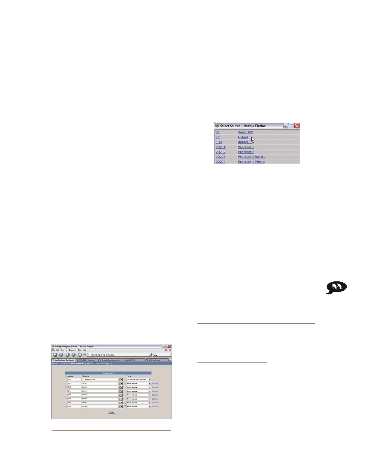
sides of the audio source and sends the summed
signal to the recorder’s left channel.
Summed-Mono to Right: Same as above, but
»
sends summed audio to the recorder’s right chan-
nel.
That’s the last option. Click on the Save Changes
button at the bottom of the page.
Congratulations — you’ve just created your first
Source Profile! You can now bring up your new source
on any Element fader.
Adding Backfeeds and GPIO
to a Source Prole
Use your Web browser to connect with the Audio
2.
Node you’ll be sending your backfeed to. Choose
Destinations from the main menu to enter the
Destinations screen (Figure 2-3); we’ll set up our-
mix-minus for output #7.
Just to the right of each Channel name box , you’ll
3.
see a “list” icon. Click on the list icon for output #7.
A list of available sources will pop up (Figure 2-4).
Figure 2-4: Picking a sour ce from the list box
Since making a mix-minus and mapping contact clo-
sures is often done at the same time a new Source Profile
is constructed, let’s briefly recap those procedures. (De-
tailed setup and operation instructions for your GPIO
Nodes and Audio Nodes are found in their respective
User Manuals.)
Let’s say you’ve connected a hybrid to your Ana-
log Node, named it “Hybrid”, and assigned it a channel
number of 77. You’ve constructed a Source Profile for it,
and you now want to give it a mix-minus backfeed and
set up a GPIO contact closure for the “take” and “drop”
functions. Here’s how:
Make sure that, in your hybrid’s Source Profile, the
1.
Source Type option is set to “Phone” and the Feed
to Source Mode is set to “Auto”. Also set the Back-
feed Enabled/Disabled option to “Enabled”.
Notice that the names and channel numbers of the
sources are both displayed for easy identification.
We’ll choose Hybrid from the list; the list window
closes and you’re returned to the Destinations
screen. The line for output #7 now displays the chan-
nel number and name of the source.
Now comes the step that makes this output a mix-
4.
minus. Each Destination entry line has a drop box
at the end; click on the drop-down and choose To
source.
Automagic: If the hybrid source is loaded to an
Engine and the engine is generating a mix minus
source already, the list box will show T WO identical channels for the source — but one will have
a description of “TO:” in front of it. Selecting
this source automatically selects TO SOURCE in
the TYPE box.
For a detailed description of these options and
how they operate, please refer to the 8x8 Analog
Node / 8x8 AES Node User’s Manual available at
www.AxiaAudio.com/manuals/ .
2: Conguring Inputs • 18
Figure 2-3: Analog Node Destinations screen
Click Apply.
5.
Now point your browser back to your Element Control
6.
Center page and choose GPIO Configuration from
the menu sidebar. (You may also use a GPIO Node
other than the Power Supply/GPIO that shipped with
your Element, just point your browser to that node’s
IP address instead.)
©2008 Axia Audio — Rev. 3.0
Page 29
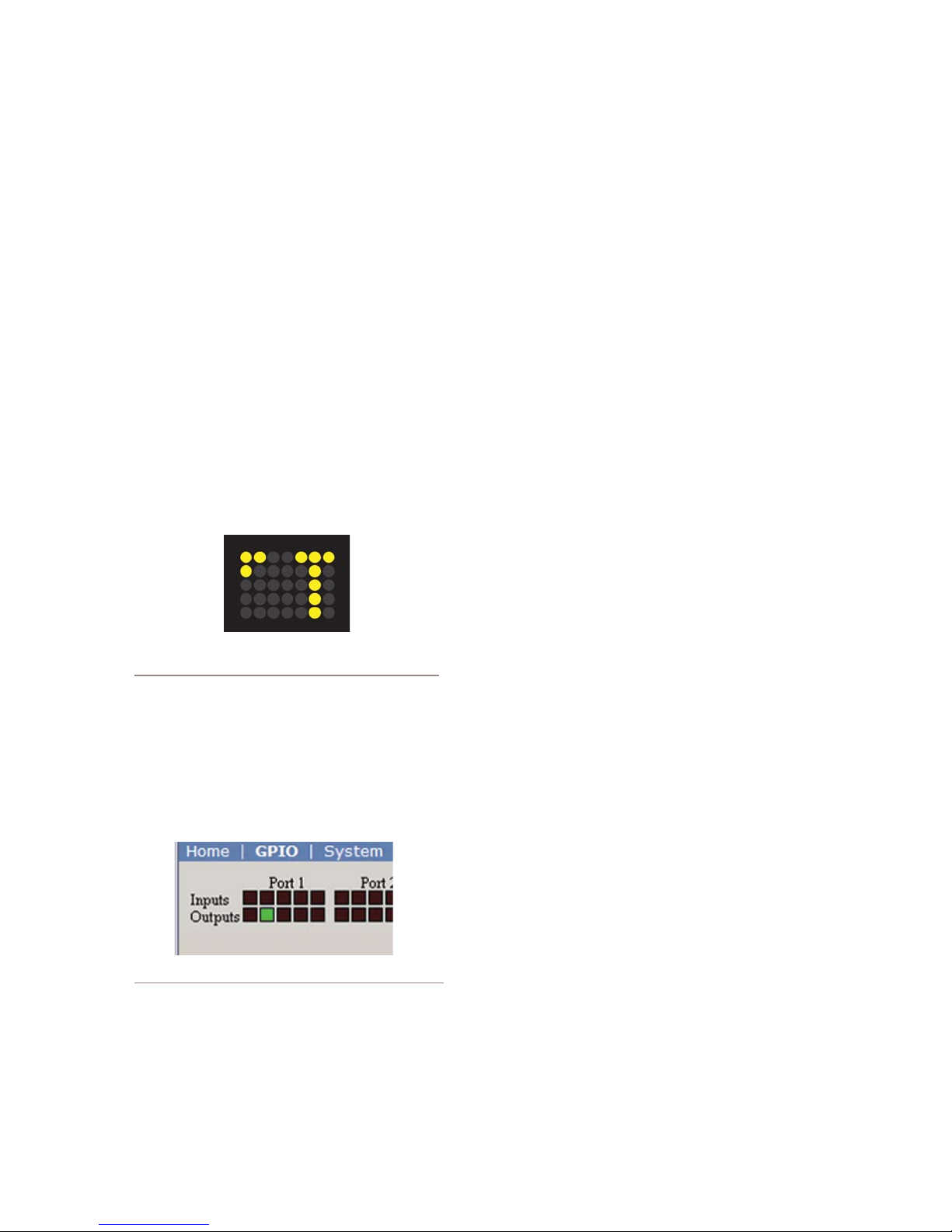
The GPIO setup screen uses the same method of as-
7.
signing devices to ports as the Analog Node. Pick a
port to map your hybrid’s contact closures to, using
the list tool, and click Apply.
The process is complete: you’ve made a Source Pro-
file for your hybrid, created a mix-minus, mapped it to
an Analog Node audio output, and associated a GPIO
contact closure with the source.
To confirm, choose the Options key at the top of any
Element fader channel and load your new Phone source.
Now press the Talk key just below the fader; you’ll see
the Status Symbol shown in Figure 2-5 appear in the
window above the channel to indicate that the operator’s
mic is talking to this telephone hybrid through it’s back-
feed channel. (Status Symbols are described in detail at
the end of Chapter Four, “Element Operations”.)
What's Next
When you’re ready, join us in Chapter Three for more
detail about setting up logic commands and GPIO ports
for your audio sources. q
Figure 2-5: Status Symbol indicates mix-minus/
talkback feed to phone source.
Also, take another look at the GPIO screen on your
browser. Note the green indicators that have appeared
on the port representing your hybrid; switch the Element
channel on and off and you’ll observe the active tally
change pins (as shown in Figure 2-6).
Figure 2-6: GPIO status indicators
2: Conguring Inputs • 19
©2008 Axia Audio — Rev. 3.0
Page 30

CAT.6, m n ,
dt n n r rt.
Eler .
2: Conguring Inputs • 20
©2008 Axia Audio — Rev. 3.0
Page 31

GPIO Port Definitions
Chapter Three:
Configuring GPIO
Since the days of rotary-switch source selectors, it’s
been a challenge to properly route machine logic along
with audio. Some complicated schemes have been de-
vised over the years, but broadcasters wanted a simple,
fast way to associate logic with audio in a routable en-
vironment.
Since the Axia IP-Audio system was designed as
a true computer network, we were able to start with a
clean sheet of paper to design the first truly routable ma-
chine logic/audio interface. Unlike conventional logic
connections which require each command circuit to be
wired individually, Axia sends machine controls over
the same Ethernet your audio travels on, further reduc-
ing infrastructure, cost and tedium.
Along with controlling external audio devices,
Element’s GPIO interface also includes logic commands
for routine studio/control room operations such as tally
lights, monitor muting, On-Air lights and more.
This chapter explains how to set up Element GPIO
to handle these functions. (We assume you’ve already
read the GPIO Node User’s Manual, familiarized your-
self with its controls, and assigned it an IP. If not, we
strongly recommend you do so, as this chapter is not
designed to be a comprehensive primer.)
Note: Your Element ships with a combination
GPIO Node/Power Supply that also contains the
Element CPU. These units are convection cooled,
and we strongly recommend that, when rackmounting these units, you leave at least 1RU of
space above and below the GPIO Node/Power
Supply to ensure adequate ventilation.
Each Axia GPIO has eight DB-15 connectors on its
back panel. Each connector can be associated with a de-
vice in your studio, and provides five opto-isolated in-
puts and 5 opto-isolated outputs per device for machine
control, lamp drives and remote channel controls.
GPIO ports are programmed to support several dif-
ferent types of devices. How does a GPIO port “know”
which type of device is assigned to it? Well, there’s a
little bit of magic involved.
Back in Chapter Two, when you constructed a Source
Profile for a telephone hybrid, you defined the source
type (see “Adding Backfeeds and GPIO to a Source Pro-
file,” p. 12). This is important, because when that source
is assigned to a console fader, Element uses this Source
Profile selection to tell the GPIO Node what sort of com-
mand to send to the attached device..
If Element “sees” in the Source Profile that the as-
signed device is a microphone, it tells the GPIO Node to
send logic for On, Off, Remote Mute and Remote Talk
commands on the appropriate pins. If it “sees” a line
input, it tells the GPIO Node to send Start, Stop and
Reset commands, plus closures for Ready lights, etc.
Axia GPIO ports can deliver command sets for the
following devices:
Microphone (Operator, Guest or Producer)
1.
Line Input
2.
Codec
3.
Telephone Hybrid
4.
Computer Playback Device
5.
Control Room Monitor
6.
Studio Monitor
7.
Profanity Delay Device
8.
Accessory Button Panel Device
9.
The next few pages contain tables that explain what
function the pins provide in each different device mode.
3: Conguring GPIO • 21
©2008 Axia Audio — Rev. 3.0
Page 32
GPIO Operator’s Microphone Logic
6'.$
3/52#%
/54054
#/--/.
2%452.
/54
/54
/54
/54
/54
.#
).
).
).
).
).
).
#/-
6
0/7%2
3/52#%
Name Pin Type Notes
INPUTS
ON Command 11 Active L ow Input Turns channel ON
OFF Command 12 Active L ow Input Turn channel OFF
TALK (to Monitor 2) Command 13 Active Low Input Activates the Element TALK
MUTE Command 14 Active L ow Input Mutes channel outputs
TALK (to PREVIEWED
15 Active L ow Input Activates the TALK button
SOURCE) Command
OUTPUTS
ON Lamp 1 Open Collector to Logic Com-
mon Return
OFF Lamp 2 Open Collector to Logic Com-
mon Return
TALK (to Monitor 2) Lamp 3 Open Collector to Logic Com-
mon Return
MUTE L amp 4 Open Collector to Logic Com-
mon Return
TALK (to PREVIEWED
SOURCE) L amp
5 Open Collec tor to Logic Com-
mon Return
POWER & COMMON
Source Common 7 Logic Common Connect to ground of source
Logic Common 8 Internal 5 Volt return Can be connected to Pin 7
Logic +5 Volt Supply 9 Logic Supply, Individually
Fused
Input Common 10 Common for all 5 input s Connect to power supply of
NOT CONNECTED 6
TO MON2 function and r outes
mic audio to the Talkback bus.
on every source currently in
preview and routes mic audio
to the Talkback bus.
Illuminate s when channel is
ON unless TALK or MUTE is
active
Illuminate s when channel is
OFF
Illuminate s when TALK TO
MON2 is active
Illuminate s when MUTE is
active
Illuminate s when TALK to
PREVIEWED SOURCE is active.
device or to Pin 8
if source is not providing
common
Can be connected to Pin 10 if
source is not providing voltage; active only when source
has been assigned to channel.
source device or to Pin 9
3: Conguring GPIO • 22
GPIO v.”Z” 12/2007
©2008 Axia Audio — Rev. 3.0
Page 33
GPIO Control Room Guest Microphone Logic
6'.$
3/52#%
/54054
#/--/.
2%452.
/54
/54
/54
/54
/54
.#
).).
).).).).#/-
6
0/7%2
3/52#%
Name Pin Type Notes
INPUTS
ON Command 11 Active L ow Input Turns channel ON
OFF Command 12 Active L ow Input Turn channel OFF
TALK (to CR) Command 13 Active L ow Input Mutes channel outputs and
MUTE Command 14 Active L ow Input Mutes channel outputs
TALK (to SOURCE) Command 15 Active Low Input Allows an external button
OUTPUTS
ON Lamp 1 Open Collector to Logic Com-
mon Return
OFF Lamp 2 Open Collector to Logic Com-
mon Return
TALK (to CR) Lamp 3 Open Collec tor to Logic Com-
mon Return
MUTE L amp 4 Open Collector to Logic Com-
mon Return
TALK (to SOURCE) Lamp 5 Open Collec tor to Logic Com-
mon Return
POWER & COMMON
Source Common 7 Logic Common Connect to ground of source
Logic Common 8 Internal 5 Volt return Can be connected to Pin 7
Logic + 5 Volt supply 9 Logic Supply, Individually
Fused
Source Supply 10 Common for all 5 input s Connect to power supply of
NOT CONNECTED 6
routes source audio to PVW
speaker s
to activate channel TALK TO
SOURCE function. (Element
only; SmartSurface not used)
Illuminate s when channel is
ON unless TALK or MUTE is
active
Illuminate s when channel is
OFF
Illuminate s when TALK is
active
Illuminate s when MUTE is
active
Illuminate s when the channel
TALK TO SOURCE function
is active. (Element only;
Smart Surface not used)
device or to Pin 8
if source is not providing
common
Can be connected to Pin 10 if
source is not providing voltage; active only when source
has been assigned to channel.
source device or to Pin 9
©2008 Axia Audio — Rev. 3.0
GPIO v.”Z” 12/2007
3: Conguring GPIO • 23
Page 34
GPIO Studio (Monitor 2) Guest Microphone Logic
6'.$
3/52#%
/54054
#/--/.
2%452.
/54
/54
/54
/54
/54
.#
).).
).).).).#/-
6
0/7%2
3/52#%
Name Pin Type Notes
INPUTS
ON Command 11 Active L ow Input Turns channel ON
OFF Command 12 Active L ow Input Turn channel OFF
TALK (to CR) Command 13 Active L ow Input Mutes channel outputs and
MUTE Command 14 Active L ow Input Mutes channel outputs
TALK (to SOURCE) Command 15 Active Low Input Allows an external button
OUTPUTS
ON Lamp 1 Open Collector to Logic Com-
mon Return
OFF Lamp 2 Open Collector to Logic Com-
mon Return
TALK (to CR) Lamp 3 Open Collec tor to Logic Com-
mon Return
MUTE L amp 4 Open Collector to Logic Com-
mon Return
TALK (to SOURCE) Lamp 5 Open Collec tor to Logic Com-
mon Return
POWER & COMMON
Source Common 7 Logic Common Connect to ground of source
Logic Common 8 Internal 5 Volt return Can be connected to Pin 7
Logic + 5 Volt supply 9 Logic Supply, Individually
Fused
Source Supply 10 Common for all 5 input s Connect to power supply of
NOT CONNECTED 6
routes source audio to PVW
speaker s
to activate channel TALK TO
SOURCE function. (Element
only; SmartSurface not used)
Illuminate s when channel is
ON unless TALK or MUTE is
active
Illuminate s when channel is
OFF
Illuminate s when TALK is
active
Illuminate s when MUTE is
active
Illuminate s when the channel
TALK TO SOURCE function
is active. (Element only;
Smart Surface not used)
device or to Pin 8
if source is not providing
common
Can be connected to Pin 10 if
source is not providing voltage; active only when source
has been assigned to channel.
source device or to Pin 9
3: Conguring GPIO • 24
GPIO v.”Z” 12/2007
©2008 Axia Audio — Rev. 3.0
Page 35
GPIO Producer’s Microphone Logic
6'.$
3/52#%
/54054
#/--/.
2%452.
/54
/54
/54
/54
/54
.#
).
).
).
).
).
).
#/-
6
0/7%2
3/52#%
Name Pin Type Notes
INPUTS
ON Command 11 Active L ow Input Turns channel ON
OFF Command 12 Active L ow Input Turn channel OFF
TALK (to MONITOR 2)
Command
MUTE Command 14 Active L ow Input Mutes channel outputs
TALK (to PREVIEWED
SOURCE) Command
OUTPUTS
ON Lamp 1 Open Collector to Logic Com-
OFF Lamp 2 Open Collector to Logic Com-
TALK (to MONITOR 2) Lamp 3 Open Collec tor to Logic Com-
MUTE L amp 4 Open Collector to Logic Com-
TALK (to PREVIEWED
SOURCE) L amp
POWER & COMMON
Source Common 7 Logic Common Connect to ground of source
Logic Common 8 Internal 5 Volt return Can be connected to Pin 7
Logic + 5 Volt supply 9 Logic Supply, Individually
Source Supply 10 Common for all 5 input s Connect to power supply of
NOT CONNECTED 6
13 Active L ow Input Activates the Element TALK
to MON2 function and r outes
mic audio to the Talkback bus.
15 Active L ow Input Activates the TALK button
on every source currently in
Preview and routes mic audio
to the Talkback bus.
Illuminate s when channel is
mon Return
ON unless TALK or MUTE is
active
Illuminate s when channel is
mon Return
OFF
Illuminate s when TALK to
mon Return
MON2 is active.
Illuminate s when MUTE is
mon Return
5 Open Collec tor to Logic Com-
mon Return
active
Illuminate s when TALK to
PREVIEWED SOURCE is active.
device or to Pin 8
if source is not providing
common
Can be connected to Pin 10 if
Fused
source is not providing volt-
age; active only when source
has been assigned to channel.
source device or to Pin 9
©2008 Axia Audio — Rev. 3.0
GPIO v.”Z” 12/2007
3: Conguring GPIO • 25
Page 36
GPIO Line Input Logic
6'.$
3/52#%
/54054
#/--/.
2%452.
/54
/54
/54
/54
/54
.#
).
).
).
).
).
).
#/-
6
0/7%2
3/52#%
Name Pin Type Notes
INPUTS
ON Command 11 Active Low Input Turns channel ON
OFF Command 12 Active L ow Input Turns channel OFF & sends
PREVIEW Command 13 Active Low Input Turns preview ON
RESET Command 14 Active Low Input Turns c hannel OFF, while not
READY Command 15 Active Low Input Illuminates OFF lamp to indi-
OUTPUTS
ON Lamp 1 Open Collector to Logic Com-
mon Return
OFF Lamp 2 Open Collector to Logic Com-
mon Return
PREVIEW Lamp 3 Open Collector to Logic Com-
mon Return
START Pulse 4 Open Collector to Logic Com-
mon Return
STOP Pulse 5 Open Collector to Logic Com-
mon Return
POWER & COMMON
Source Common 7 Logic Common Connect to ground of source
Logic Common 8 Internal 5 Volt return Can be connected to Pin 7 if
Logic + 5 Volt supply 9 Logic Supply, Individually
Fused
Source Supply 10 Common for all 5 inputs Connect to power supply of
NOT CONNECTED 6
100 msec STOP pulse
sending a STOP pulse
cate source’s readiness
Illuminate s when channel is
ON
Illuminate s when channel is
OFF and READY is active
Illuminate s when PRE VIEW
is ON
A 100 msec pulse when the
channel status changes from
OFF to ON
A 100 msec pulse when the
channel status changes from
ON to OFF
device or to Pin 8
source is not providing common
Can be connected to Pin 10
if source is not providing
voltage; active only when
source has been assigned to
channel.
source device or to Pin 9
3: Conguring GPIO • 26
GPIO v.”Z” 12/2007
©2008 Axia Audio — Rev. 3.0
Page 37
GPIO Codec Logic
6'.$
3/52#%
/54054
#/--/.
2%452.
/54
/54
/54
/54
/54
.#
).
).
).
).
).
).
#/-
6
0/7%2
3/52#%
Name Pin Type Notes
INPUTS
ON Command 11 Active Low Input Turns c hannel ON
OFF Command 12 Active L ow Input Turns channel OFF
TALK (to CR) Command 13 Ac tive Low Input Mutes channel outputs and
MUTE Command 14 Active Low Input Mutes channel outputs
TALK (to SOURCE) Command 15 Active Low Input Allows an external button
OUTPUTS
ON Lamp 1 Open Collector to Logic Com-
mon Return
OFF Lamp 2 Open Collector to Logic Com-
mon Return
TALK (to CR) Lamp 3 Open Collector to Logic Com-
mon Return
MUTE L amp 4 Open Collec tor to Logic Com-
mon Return
TALK (to SOURCE) Lamp 5 Open Collec tor to Logic Com-
mon Return
POWER & COMMON
Source Common 7 Logic Common Connect to ground of source
Logic Common 8 Internal 5 Volt return Can be connected to Pin 7 if
Logic + 5 Volt supply 9 Logic Supply, Individually
Fused
Source Supply 10 Common for all 5 inputs Connect to power supply of
NOT CONNECTED 6
routes source audio to PVW
speaker s
to activate channel TALK TO
SOURCE function.
Illuminate s when channel is
ON unless TALK or MUTE are
active
Illuminate s when channel is
OFF.
Illuminate s when TALK is
active
Illuminate s when MUTE is
active
Illuminate s when the channel
TALK TO SOURCE function is
active.
device or to Pin 8
source is not providing common
Can be connected to Pin 10
if source is not providing
voltage; active only when
source has been assigned to
channel.
source device or to Pin 9
©2008 Axia Audio — Rev. 3.0
GPIO v.”Z” 12/2007
3: Conguring GPIO • 27
Page 38
GPIO Telephone Hybrid Logic
6'.$
3/52#%
/54054
#/--/.
2%452.
/54
/54
/54
/54
/54
.#
).
).
).
).
).
).
#/-
6
0/7%2
3/52#%
Name Pin Type Notes
INPUTS
ON Command 11 Active Low Input Turns c hannel ON
OFF Command 12 Active L ow Input Turns channel OFF
PREVIEW Command 13 Active Low Input Turns preview ON
RESET Command 14 Active Low Input Turns c hannel of f while not
READY Command 15 Active Low Input Illuminates OFF lamp to indi-
OUTPUTS
ON Lamp 1 Open Collector to Logic Com-
mon Return
OFF Lamp 2 Open Collector to Logic Com-
mon Return
PREVIEW Lamp 3 Open Collector to Logic Com-
mon Return
START Pulse 4 Open Collector to Logic Com-
mon Return
STOP Pulse 5 Open Collector to Logic Com-
mon Return
POWER & COMMAND
Source Common 7 Logic Common Connect to ground of source
Logic Common 8 Internal 5 Volt return Can be connected to Pin 7 if
Logic + 5 Volt supply 9 Logic Supply, Individually
Fused
Source Supply 10 Common for all 5 inputs Connect to power supply of
NOT CONNECTED 6
sending a STOP pulse
cate source’s readiness
Illuminate s when channel is
ON
Illuminate s when channel is
OFF
Illuminate s when PRE VIEW
is ON
A 100 mS PULSE is sent when
channel is rst turned ON or
when PV W is rst selected
(if “PVW answers” option is
selec ted).
A 100 mS PULSE sent when
channel is turned OFF.
device or to Pin 8
source is not providing common
Can be connected to Pin 10
if source is not providing
voltage; active only when
source has been assigned to
channel.
source device or to Pin 9
3: Conguring GPIO • 28
GPIO v.”Z” 12/2007
©2008 Axia Audio — Rev. 3.0
Page 39
GPIO Control Room Monitor Logic
6'.$
3/52#%
/54054
#/--/.
2%452.
/54
/54
/54
/54
/54
.#
).
).
).
).
).
).
#/-
6
0/7%2
3/52#%
Name Pin Type Notes
INPUTS
MUTE CR Command 11 Active Low Input Mutes CR monitors and Pre-
DIM CR Command 12 Active Low Input Allows external dimming of
Enable EXT PRE VIEW Com-
13 Active Low Input Feeds External Audio Input to
mand
Not Used 14 Ac tive Low Input
TALK TO EX T Command
15 Active Low Input Turns on Talk to External
(Element only).
OUTPUTS
CR ON AIR L amp 1 Open Collector to L ogic Com-
mon Return
DIM CR Lamp 2 Open Collector to Logic Com-
mon Return
PREVIEW Lamp 3 Open Collector to Logic Com-
mon Return
Not Used 4 Open C ollector to Logic Com-
mon Return
TALK (to CR) Active Lamp 5 Open Collector to Logic Com-
mon Return
POWER & COMMON
Source Common 7 Logic Common Connect to ground of source
Logic Common 8 Internal 5 Volt return Can be connected to Pin 7 if
Logic + 5 Volt supply 9 Logic Supply, Individually
Fused
Source Supply 10 Common for all 5 inputs Connect to power supply of
NOT CONNECTED 6
view speakers
CR monitor speakers.
PREVIEW
Audio on Element.
Illuminate s whenever CR
monitors are muted
Illuminate s whenever control
room monitors are DIMMED
Illuminate s when PRE VIEW is
active.
Active whenever a source has
activated its TALK (to CR)
function
device or to Pin 8
source is not providing common
Can be connected to Pin 10
if source is not providing
voltage; active only when
source has been assigned to
channel.
source device or to Pin 9
©2008 Axia Audio — Rev. 3.0
GPIO v.”Z” 12/2007
3: Conguring GPIO • 29
Page 40
GPIO Studio Monitor Logic
6'.$
3/52#%
/54054
#/--/.
2%452.
/54
/54
/54
/54
/54
.#
).
).
).
).
).
).
#/-
6
0/7%2
3/52#%
Name Pin Type Notes
INPUTS
MUTE Studio Command 11 Active Low Input Allows external muting of
DIM Studio/Monitor 2
12 Active Low Input Allows external dimming of
Command
Remote Event Timer Trigger
13 Active Low Input Resets Countup Event Timer
Command
Remote Countdown Timer
14 Active Low Input Resets Countdown timer to
Trigger Command
Not Used 15 Ac tive Low Input
OUTPUTS
Studio ON A IR Lamp 1 Open Collector to Logic Com-
mon Return
DIM Studio/Monitor 2 Lamp 2 Open Collector to Logic Com-
mon Return
Event Timer Trigger Output 3 Open Collector to Logic Com-
mon Return
Countdown Timer Trigger
Output
TALK TO STUDIO/MONITOR 2
Active L amp
4 Open Collector to Logic Com-
mon Return
5 Open Collector to Logic Com-
mon Return
POWER & COMMON
Source Common 7 Logic Common Connect to ground of source
Logic Common 8 Internal 5 Volt return Can be connected to Pin 7 if
Logic + 5 Volt supply 9 Logic Supply, Individually
Fused
Source Supply 10 Common for all 5 inputs Connect to power supply of
NOT CONNECTED 6
Studio monitor speakers.
Studio monitor speakers.
to zero and starts timer.
preset max time and starts
timer (Element only).
Illuminate s whenever Studio
monitors are muted
Illuminate s whenever Studio
monitors are DIMMED
A 100 ms PULSE sent when
event timer is started from
zero.
A 100 mS PULSE sent when
countdown timer is started
from preset max (Element
only).
Illuminate s whenever the
TALK TO STUDIO/MON2 function is ac tive.
device or to Pin 8
source is not providing common
Can be connected to Pin 10
if source is not providing
voltage; active only when
source has been assigned to
channel.
source device or to Pin 9
3: Conguring GPIO • 30
GPIO v.”Z” 12/2007
©2008 Axia Audio — Rev. 3.0
Page 41
GPIO Computer Playback Device Logic
6'.$
3/52#%
/54054
#/--/.
2%452.
/54
/54
/54
/54
/54
.#
).
).
).
).
).
).
#/-
6
0/7%2
3/52#%
Name Pin Type Notes
INPUTS
ON Command 11 Active Low Input Turns c hannel ON
OFF Command 12 Active L ow Input Turns channel OFF & sends
PREVIEW Command 13 Active Low Input Turns preview ON
Not Used 14 Ac tive Low Input
READY Command 15 Active Low Input Illuminates OFF lamp to indi-
OUTPUTS
NEXT Pulse 1 Open Collector to Logic Com-
mon Return
OFF Lamp 2 Open Collector to Logic Com-
mon Return
PREVIEW Lamp 3 Open Collector to Logic Com-
mon Return
START Pulse 4 Open Collector to Logic Com-
mon Return
STOP Pulse 5 Open Collector to Logic Com-
mon Return
POWER & COMMON
Source Common 7 Logic Common Connect to ground of source
Logic Common 8 Internal 5 Volt return Can be connected to Pin 7 if
Logic + 5 Volt supply 9 Logic Supply, Individually
Fused
Source Supply 10 Common for all 5 inputs Connect to power supply of
NOT CONNECTED 6
100 msec STOP pulse
cate source’s readiness
A 100 mS PULSE sent when
ON button is depressed, except when initially turned ON.
Illuminate s when channel is
OFF and READY is active
Illuminate s when PRE VIEW
is ON
A 100 mS PULSE sent when
channel is rst turned ON.
A 100 mS PULSE sent when
channel is turned OFF.
device or to Pin 8
source is not providing common
Can be connected to Pin 10
if source is not providing
voltage; active only when
source has been assigned to
channel.
source device or to Pin 9
©2008 Axia Audio — Rev. 3.0
GPIO v.”Z” 12/2007
3: Conguring GPIO • 31
Page 42
GPIO External Profanity Delay Logic
6'.$
3/52#%
/54054
#/--/.
2%452.
/54
/54
/54
/54
/54
.#
).).
).
).
).
).
#/-
6
0/7%2
3/52#%
Name Pin Type Notes
INPUTS
DUMP Lamp 11 Ac tive Low Input Illuminates DUMP lamp
EXIT Lamp 12 Active Low Input Illuminates EXIT lamp.
PAUSE Lamp 13 Active Low Input Illuminates PAUSE lamp.
ENGAGE Lamp 14 Active Low Input Illuminates ENGAGE lamp.
DELAY ANNUNCIATOR
15 Active Low Input Illuminates the DELAY annun-
Command
OUTPUTS
DUMP Switc h 1 Open Collector to Logic Com-
mon Return
EXIT Switch 2 Open Collector to Logic Com-
mon Return
PAUSE Switch 3 Open Collector to Logic Com-
mon Return
ENGAGE Switch 4 Open Collector to Logic Com-
mon Return
Not Used 5 Open C ollector to Logic Com-
mon Return
POWER & COMMON
Source Common 7 Logic Common Connect to ground of source
Logic Common 8 Internal 5 Volt return Can be connected to Pin 7 if
Logic + 5 Volt supply 9 Logic Supply, Individually
Fused
Source Supply 10 Common for all 5 inputs Connect to power supply of
NOT CONNECTED 6
(located on Element Monitor
Module).
ciator on the Element main
screen.
Active when DUMP but ton is
depressed.
Active when EXIT button is
depressed.
Active when PAUSE button is
depressed.
Active when ENGAGE button
is depressed.
device or to Pin 8
source is not providing common
Can be connected to Pin 10
if source is not providing
voltage; active only when
source has been assigned to
channel.
source device or to Pin 9
3: Conguring GPIO • 32
GPIO v.”Z” 12/2007
©2008 Axia Audio — Rev. 3.0
Page 43
GPIO Film Legendable User Button Module / Accessory Panel / Rack Panel
6'.$
3/52#%
/54054
#/--/.
2%452.
/54
/54
/54
/54
/54
.#
).).
).).).).#/-
6
0/7%2
3/52#%
Name Pin Type Notes
INPUTS
User Button 1 Lamp 11 Active Low Input Illuminates User But ton 1
User Button 2 Lamp 12 Active Low Input Illuminates User But ton 2
User Button 3 Lamp 13 Active Low Input Illuminates User But ton 3
User Button 4 Lamp 14 Active Low Input Illuminates User But ton 4
User Button 5 Lamp 15 Active Low Input Illuminates User But ton 5
OUTPUTS
User Button 1 Switc h 1 Open Collector to Logic Com-
mon Return
User Button 2 Switc h 2 Open Collector to Logic Com-
mon Return
User Button 3 Switc h 3 Open Collector to Logic Com-
mon Return
User Button 4 Switc h 4 Open Collector to Logic Com-
mon Return
User Button5 Switc h 5 Open Collector to Logic Com-
mon Return
POWER & COMMON
Source Common 7 Logic Common Connect to ground of source
Logic Common 8 Internal 5 Volt return Can be connected to Pin 7 if
Logic + 5 Volt supply 9 Logic Supply, Individually
Fused
Source Supply 10 Common for all 5 inputs Connect to power supply of
NOT CONNECTED 6
Lamp
Lamp
Lamp
Lamp
Lamp
Active when User Button 1 is
pushed
Active when User Button 2 is
pushed
Active when User Button 3 is
pushed
Active when User Button 4 is
pushed
Active when User Button 5 is
pushed
device or to Pin 8
source is not providing common
Can be connected to Pin 10
if source is not providing
voltage; active only when
source has been assigned to
channel.
source device or to Pin 9
©2008 Axia Audio — Rev. 3.0
GPIO v.”Z” 12/2007
3: Conguring GPIO • 33
Page 44
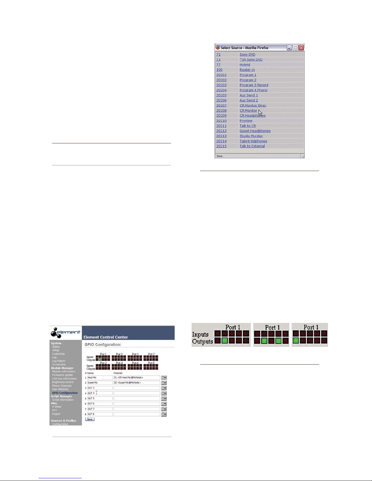
Assigning GPIO to a Source
As you’ve seen by studying the previous pages, a lot
of the work of assigning logic to a source is done for you;
once a GPIO port is linked with a Source Profile, all that
remains to do is to solder cables connecting the GPIO’s
DB-15 connectors to the device’s control interface.
So, how do you link a GPIO port with a Source Pro-
file? It’s very easy; let’s do it step-by-step.
Note: This procedure assumes that you have
already dened at least one Source Prole using
the instructions outlined in Chapter Two.
Figure 3-3: GPIO Select Source popup list
Open your Web browser and enter the IP address of
1.
your Element console. Choose GPIO Conguration
from the Element Control Center menu. Enter your
password if prompted (default login is “user”, leave
the password field blank).
If you haven’t previously assigned any GPIO ports,
2.
the GPIO definitions screen will be blank. Notice the
status indicators at the top of the page, showing the
state of the input and output pins of each port. Click
on the list icon to the right of an unused line.
When you click on any list icon, a small popup win-
3.
dow will open, enumerating all of the audio sourc-
es available on the Livewire network (Figure 3-3).
Choose the source you wish to associate with a GPIO
port by clicking on it; the window will close and the
source’s name and channel number will appear in
the Channel box.
Type a descriptive name in the Name field, and click
4.
on the Save button at the bottom of the page.
Look at the page-top status indicator for Port 1.
5.
You’ll see that one of the pin status indicators is
lit in green; this means that the port is now send-
ing a GPIO logic state of “true” through this
pin. Assign the source for which you just created
a GPIO link to a Element channel; operate the
On and Off keys for the channel and watch the
pin status indicators change as you do so.
The source we’ve been using for this demonstra-
tion is a telephone hybrid; we can now observe the
pin status indicators change as we turn the channel
on and off, as shown in Figure 3-4.
Figure 3-4: Pin status indicators showing
GPIO por t activity
3: Conguring GPIO • 34
Figure 3-2: GPIO denitions page
Referring to the Hybrid Logic Chart on Page 28, we
can see that when the Element channel is Off, the
indicator representing Output Pin 2 – the Off Lamp
logic command – is high. Turning the channel On,
we see Pin 4 pulse briefly before Pin 1 goes high:
the GPIO has just sent a Start pulse, then lit the
On Lamp. If you turn the channel Off again, you’ll
observe a Stop pulse, and the Off Lamp command
©2008 Axia Audio — Rev. 3.0
Page 45
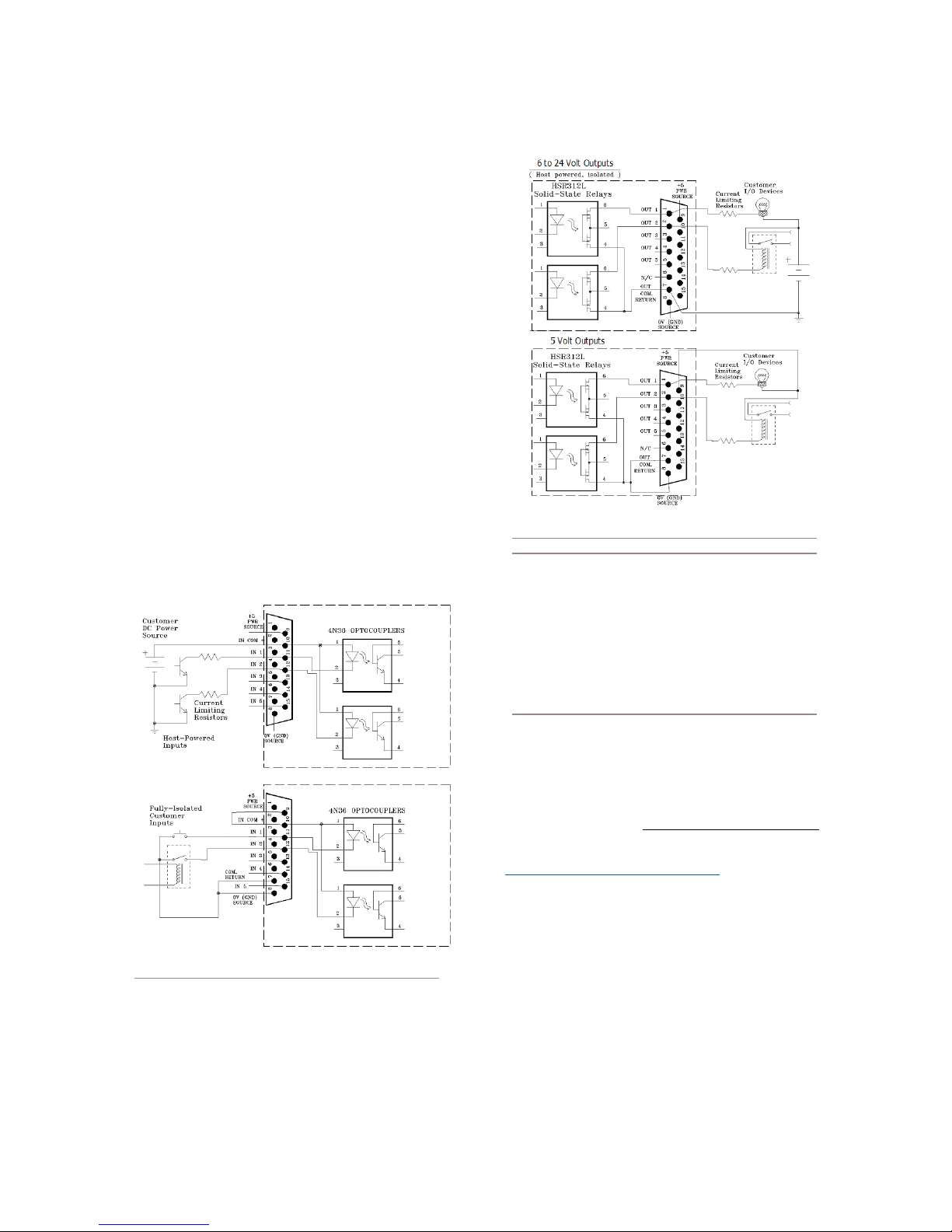
once again become active.
See how easy that was? Simply assigning an existing
audio source to a GPIO port automagically configures
the port for the type of device supplying the audio, and
send the appropriate logic commands to that port when
the source is assigned to a Element channel.
A word about the GPIO Ports
Input Connections
Current on these inputs must be limited to 20 mA or
less, through the use of a current-limiting resistor. An
external power source (24 volts DC maximum) is rec-
ommended for all inputs and outputs, to prevent ground
loops between equipment. However, if customer equip-
ment is completely isolated, using power from the GPIO
Port connectors is acceptable. Figure 3-5 shows details
for both types of connections:
for outputs:
Figure 3-6: GPIO output connections
Note: Some external devices will allow a logic
control input “sink to ground” to activate. Thus,
some devices may not work with an Axia GPO
control, because they may not fully achieve
ground through the output transistor. The voltage drop between the collector and emitter may
not be low enough to activate the device, so an
external relay controlled by the GPO may need
to be used to provide a “dry” contact closure to
the external device.
Figure 3-5: GPIO input connections
Output Connections
The GPIO node’s outputs are opto-isolated. Current
should be limited 100 mA through each output, with the
total current draw from the +5 Volt supply not to exceed
3 amps. Figure 3-6 shows the recommended connections
©2008 Axia Audio — Rev. 3.0
Please note that this section is provided only as a
“jump-start” introduction to Axia GPIO nodes. For a full
understanding of the GPIO node’s options and require-
ments, please read the GPIO Node User’s Manual in-
cluded with your GPIO node, or available for download
at www.AxiaAudio.com/downloads/ .
What's Next
When you’re ready, join us in Chapter Four for a
comprehensive walk-through of Element operations. q
3: Conguring GPIO • 35
Page 46

wr s
r roacts cu.
UPS rs!
3: Conguring GPIO • 36
©2008 Axia Audio — Rev. 3.0
Page 47

Chapter Four:
Element Operations
Displays
Unlike other control surfaces, Element does not in-
clude built-in meters or other displays. Instead, Element
GPIO/Power Supply Nodes provide a VGA output to
feed your choice of display monitors.
Once it’s installed in your studio, Element looks a lot
like a traditional radio broadcast console — but that’s
where the resemblance ends.
Element isn’t a console; it doesn’t actually mix or
process audio. It would be more accurate to say that
Element is a control center, allowing the operator to take
charge of the delivery system, the StudioEngine mix-
ing/routing engine, the phone system, the recorder/edi-
tor and other sources.
With Element, our goal is to provide you with the
most efficient man-machine interface possible for fast-
paced, complex programs where board operators must
multi-task without error. As such, Element brings a whole
new level of control and sophistication to the broadcast
studio, while providing very intuitive operation.
Overview
Element was designed to perform equally well in
air or production studios. In the air studio, the clean
interface enhances speed and accuracy without clutter
or confusing controls. In the production room, deeper
levels of sophistication are accessible with the touch of
a button.
Because different people work differently, we’ve
made it possible to access many functions in multiple
ways. By providing several paths to access a function,
the board operator has less to remember and is less like-
ly to get trapped. This also serves to bring new operators
up to speed easily.
In this chapter we’ll first give you a high-level over-
view of Element capabilities to help convey exactly what
Element is capable of. Then, we’ll give you detailed ex-
planations of the various controls and functions.
Element’s display normally shows meter levels for
all PGM buses, a time of day clock, countdown and time-
remaining timers, and well as important status messages.
When the operator adjusts console options using the Di-
rect Access Keys on the Master Module, the screen helps
navigate the options and, in the case of audio dynamics
and EQ adjustment, shows graphic representations of
the effects of changes.
Show Proles
Element can be completely reconfigured, instantly,
to suit different types of shows. By using pre-defined
Show Profiles, talent can change board settings from a
phone and microphone intensive morning show to a per-
sonality-based music show – or any other kind – at the
touch of a button.
Show Profiles are easily accessed by pressing the
Prole key located at the top of the Global Options
section of the Master Module. Element’s on-screen
display will change to display a list giving instant ac-
cess to all stored Profiles. Construction and administra-
tion of Show Profiles is covered in Chapter Five. “Show
Profiles.”
Sources, Channels and Faders
During the course of this manual, we’ll refer often to
sources and channels. These are not the same! “Sourc-
es” are microphones, CD players, outputs from the
playout system, telephone hybrids, etc. Your Livewire
network may have a very large number of sources, in
different locations, used at various times.
“Channel” would normally be used when referring to
Element’s linear pots and associated on/off controls, al-
pha displays, bus assignment keys, etc. But “Channel” is
also used when discussing numbered Livewire network
streams. To avoid confusion, we’ll call Element channel
strips “Faders”.
4: Element Operations • 37
©2008 Axia Audio — Rev. 3.0
Page 48

Sources are assigned to faders for use on-air or in
production. During initial configuration, the sources are
programmed by the engineer for appropriate logic and
options (as outlined in previous chapters); afterwards,
whenever that source is assigned to a fader, source logic
follows.
Fader settings are instantly reconfigured whenever a
source is selected, to accommodate the unique require-
ments of the source. For example, a fader controlling a
microphone source also controls appropriate monitor
mutes. A fader controlling a line source sends “start”
and “stop” commands when the channel is turned on
and off.
Sources can also be fed directly to the monitors for
auditioning without being assigned to a fader.
Mix-Minus
Mix-minus setup, especially for live broadcasts, has
always been one of the most confusing aspects of run-
ning a radio board.
Element makes mix-minus easy by automating it.
The operator never has to worry about sending a source
back to itself — it just can’t happen!
Several mix-minus choices – fixed and switching
– are possible, and are configured for each source when
Source Profiles are defined by the engineer (see Chap-
ter Two for details). Once this setup is done, no further
tweaking is needed; the operator simply uses the source.
A Status Symbol display on each fader tells operators
when a particular source has a mix minus output, and
even tells them which audio mix is being backfed.
Element will support as many outputs as there are
installed faders, each with its own automated mix minus
feed. Got 24 faders? You can have 24 mix-minuses!
GPIO
As explained in Chapter Three, each input source can
have associated GPIO (General Purpose Input/Output)
control associated with it. Element GPIO interfaces are
4: Element Operations • 38
connected to Element via the Livewire network, so you
can locate the actual machine connections either physi-
cally close to source equipment or in a central equip-
ment room.
During installation, the engineer configures sourc-
es to accept and provide logic commands by selecting
various options. Example: studio microphones may be
set up to automatically mute the studio monitor speak-
ers and illuminate an on-air warning light when turned
on. The same sources can be configured to accept GPIO
logic inputs from buttons so each studio guest can have
their own On, Off, Talk, and Mute keys (see Chapter
One, “Setup and Configuration” for details ).
Line sources can be configured to receive start and
stop commands from the Element as well. Start/stop
messages can also be passed, via Ethernet, to a com-
puter-based playout system.
Monitor Module and SoftKnobs
The Monitor Module and SoftKnobs contain Ele-
ment’s operating controls. This is where you’ll find vol-
ume and selection controls for monitors and heaphones,
as well as keys that provide fast access to show profiles,
EQ & dynamics, Aux feeds and more. There are two dif-
ferent type of Monitor Modules: one that contains only
monitor and option controls, and one that subtracts some
monitor controls but adds two faders. We’ll outline how
each type works.
Software
The Element operating system uses a high-perfor-
mance embedded Linux kernel to help ensure bullet-
proof, 24/7 operation. Software updates can be obtained
from Axia via the Internet and applied by the station en-
gineer. Axia Support recommends performing backups
or making printouts of Show Profiles and other configu-
ration data before applying new software updates.
Control Callout
On the following pages are a “bird’s-eye view” of
Element, with major controls located and their functions
explained.
©2008 Axia Audio — Rev. 3.0
Page 49
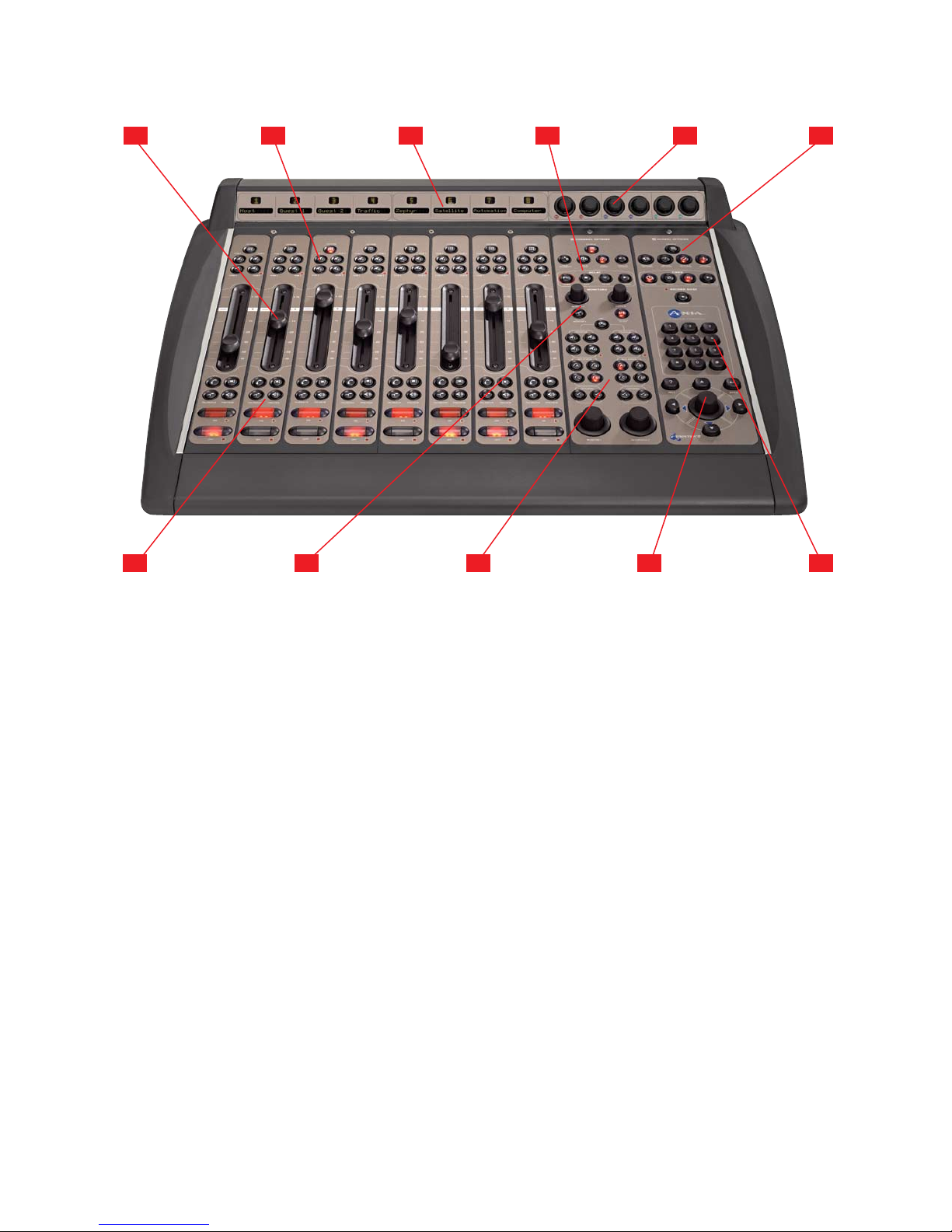
Element with Standard Monitor Module
1 2 3 4 5 6
7 8 9 1110
Faders can accommodate any input source. Each
1.
channel’s Options button (at the top of the fader
strip) lets operators change sources and call up ex-
panded channel features.
Assignment Buttons for the four stereo main
2.
output buses – Program-1, Program-2, Program-
3 and Program-4/Record – are located atop each
fader strip.
Channel Displays contain a 10-character text
3.
readout and a window for fader position numbers
and Status Symbol icons. Text is fixed for static
sources like microphones and CD players, but can
be set to show song/artist information, etc., when
computer-based audio sources are connected.
Monitor Module Options & Profanity Delay
4.
Controls. Channel Options section contains Di-
rect Access Keys for quick access to a channel’s
Source assignment, EQ, Dynamics, Pan, Mix-Mi-
nus and Aux Sends settings. These keys become
active whenever a channels Options key is pressed.
Below the Channel Options keys, a set of keys are
provided for convenient on-console control of ex-
ternal profanity-delay units.
Six SoftKnobs are context sensitive; when any
5.
Direct Access key is pressed, the on-screen dis-
play shows the function affected by rotating and/
or pushing each knob.
Monitor Module Global Options & Timer Con-
6.
trol Keys let operators recall Show Profiles, select
monitor and metering preferences and affect other
Element behaviors. Timer controls help keep track
of on-screen elapsed and remaining time displays.
Talkback & Preview Keys let operators preview
7.
(cue) selected sources off-air, or quickly talk to
any source(s) with associated backfeed(s).
Monitor 2 Talkback & Volume Controls let op-
8.
erators easily talk to hosts and guests in a second
studio, and control their monitor volume.
Monitor Assignment Section contains volume
9.
and selection controls for monitors, headphones,
Aux Send buses and Preview.
Control Knob/Nav Keys help navigate through
10.
on-screen options.
Numeric Keypad lets operators dial phone sys-
11.
tems or codecs directly. Also provides numeric
input during surface setup.
4: Element Operations • 39
©2008 Axia Audio — Rev. 3.0
Page 50
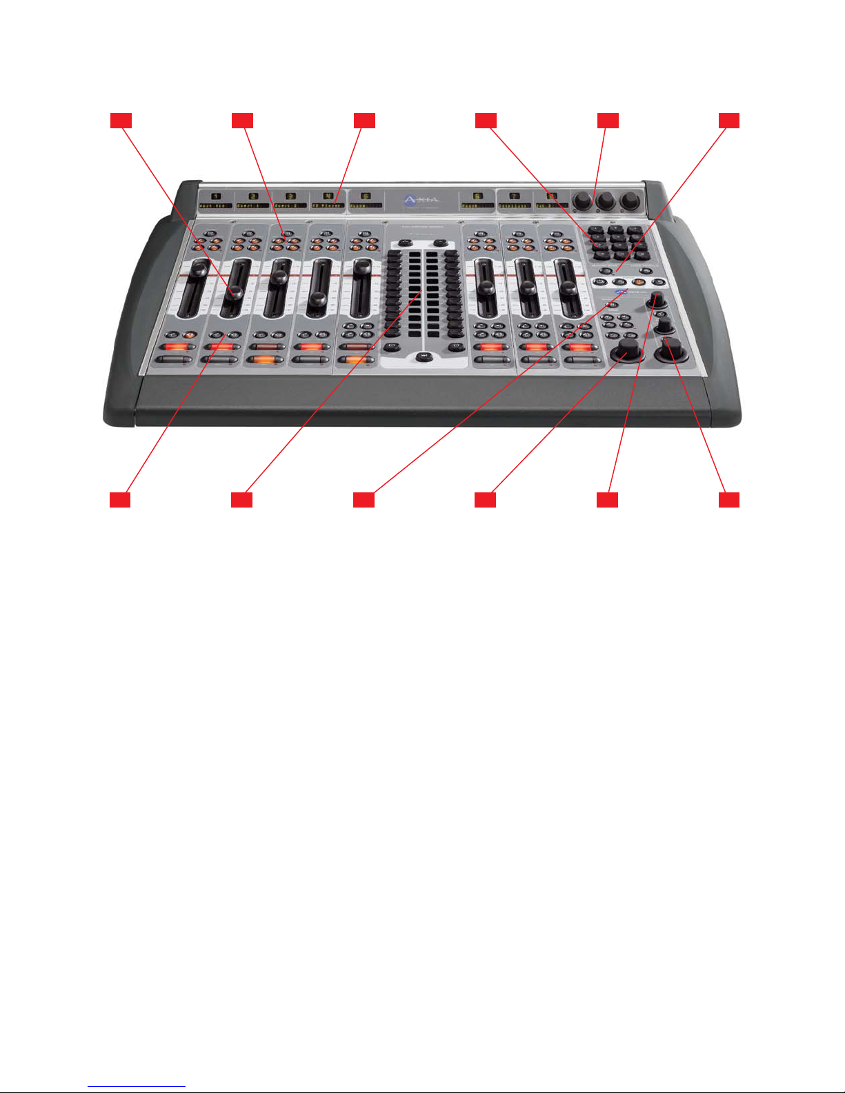
Element with 2-Fader Phone Module and 2-Fader + Monitor Module
1 2 3 4 5 6
4: Element Operations • 40
7 8 9 1110
Faders can accommodate any input source. Each
1.
channel’s Options button (at the top of the fader
strip) lets operators change sources and call up ex-
panded channel features.
Assignment Buttons for the four stereo main
2.
output buses – Program-1, Program-2, Program-
3 and Program-4/Record – are located atop each
fader strip.
Channel Displays contain a 10-character text
3.
readout and a window for fader position numbers
and Status Symbol icons. Text is fixed for static
sources like microphones and CD players, but can
be set to show song/artist information, etc., when
computer-based audio sources are connected.
Numeric Keypad lets operators dial phone sys-
4.
tems or codecs directly. Also provides numeric
input during surface setup.
Three SoftKnobs are context sensitive; when any
5.
Direct Access key is pressed, the on-screen dis-
play shows the function affected by rotating and/
Record Mode to quickly capture off-air bits to an
external recording device.
Talkback & Preview Keys let operators preview
7.
(cue) selected sources off-air, or quickly talk to
any source(s) with associated backfeed(s).
2-Fader Phone Module provides direct control
8.
of all hybrid and line control functions for Telos
Nx12, TWOx12 or Series 2101 Broadcast Talk-
show Systems.
Timer Controls help keep track of on-screen
9.
elapsed and remaining time displays.
Monitor 1 Section contains volume and selec-
10.
tion controls for monitors, headphones, Aux Send
buses and Preview.
Monitor 2 Talkback & Volume Controls let op-
11.
erators easily talk to hosts and guests in a second
studio, and control their monitor volume.
Headphone and Preview Volume Controls let
12.
operators adjust Host headphone volume and con-
trol Preview (cue) volume and options.
or pushing each knob.
Record Mode and Load Prole Keys let opera-
6.
tors recall customized Show Profiles and activate
12
©2008 Axia Audio — Rev. 3.0
Page 51
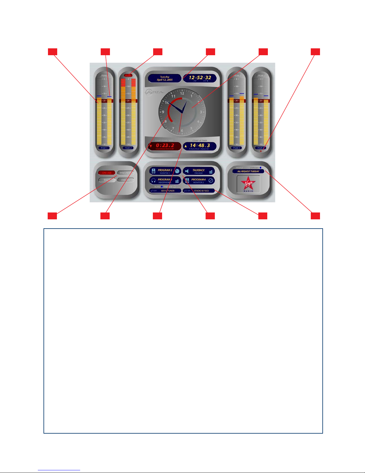
Element Stereo Main Screen Overview
1 2 3 4 5 6
7 8 9 1110
Program Meters for each of Element’s four ste-
1.
reo Program buses feature true VU meter ballistics
with an expanded scale. Solid bargraphcs indicate
average level; the red line at -20dBFS corresponds
to the 0dB mark on a traditional analog meter.
Peak Indicator indicates absolute peaks to show
2.
talent where the loudest portions of program ma-
terial are landing on the VU scale. (This indicator
may be switched off if desired.)
Peak Indicator Warning illuminates when
3.
peaks reach or exceen 0dBFS.
Day/Date and Digital Clock keep operators in-
4.
formed of what day it is (in case they forget, which
is entirely normal). Clock can be set for 12- or 24-
hour operation, and can be slaved to a networked
NTP server if desired.
Analog Clock presents a traditional clockface
5.
with second hand for fast orientation.
Utility Meter normally shows the volume of
6.
sources assigned to the PGM-4/Phone/Record
multifunction bus, but can optionally be slaved to
meter whatever source is auditioned in the Control
Room Monitors.
Annunciator Panel informs operators when Mic
7.
channels are open, when audio is being auditioned
in the Preview (cue) channel, when Talkback is ac-
tive in either direction, and when external profan-
ity delay units (if any) are active.
Countdown Ring appears when Element’s
8.
Countdown Timer is active, and decreases during
the last :60 seconds as a visual prompt.
Count Up and Countdown Timers provide an
9.
automatic event timer with manual elapsed-time
function, and a countdown timer to assist in back-
timing live program material.
Monitor Selection Indicators show talent what
10.
source is being presented in the Control Room
and Studio Monitor channels, the CR Headphone
channel and the Preview channel, and shows the
position of each volume control when adjusted.
External Monitor Indicators show what sourc-
11.
es are assigned to each of the two programmable
External Monitor channels.
Show Prole Indicator tells talent what Show
12.
Profile is currently loaded, and whether the con-
sole has been changed from Profile settings.
12
4: Element Operations • 41
©2008 Axia Audio — Rev. 3.0
Page 52
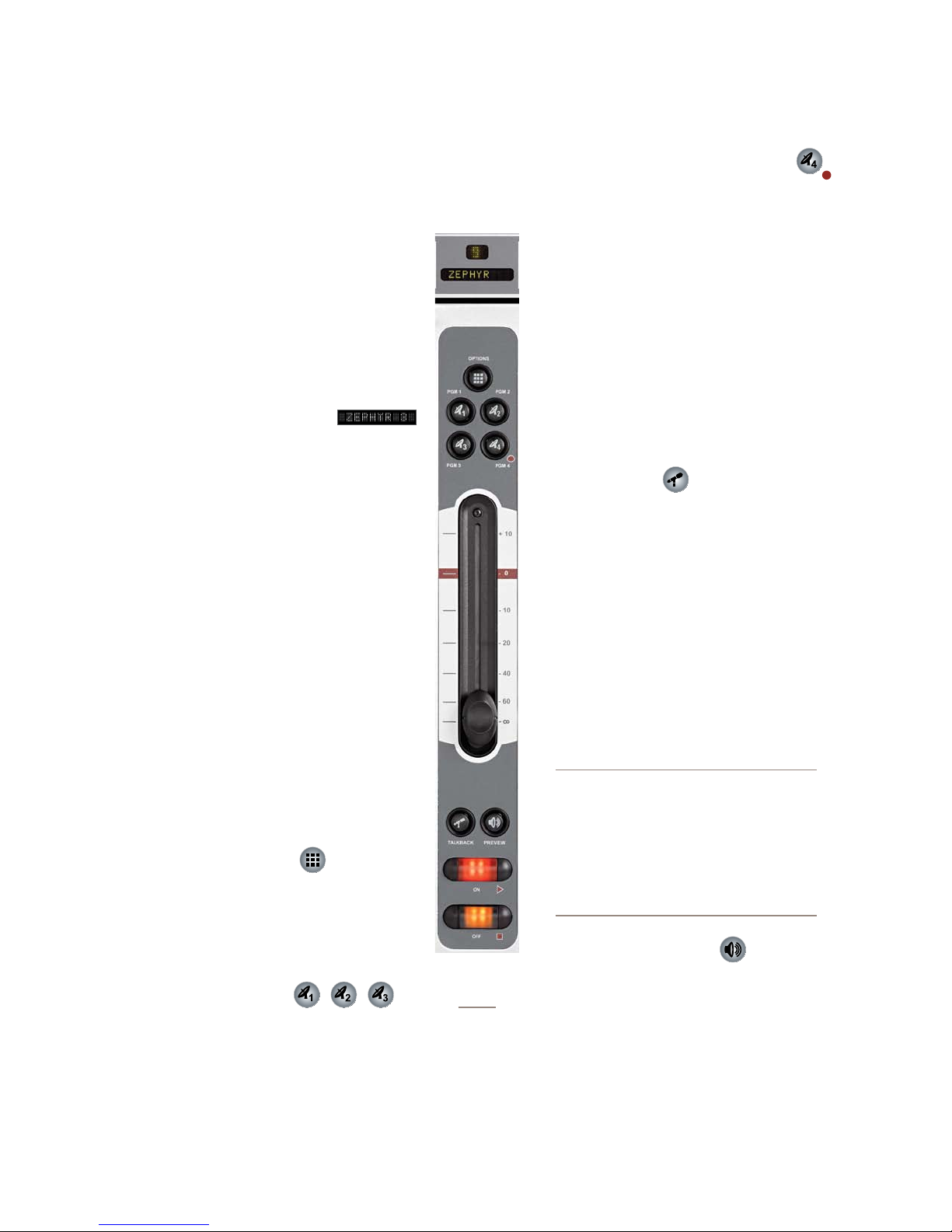
Control Details
EXTERNAL
STUDIO
PREVIEWED
SOURCE
TALK TO
and post on-off function.
4: Element Operations • 42
General Fader Controls
Although any Element faders can handle any
type of audio source, some fader functions change
their behavior depending upon the type of source
assigned. Also, certain fader modules have “ex-
tra” controls for specific uses. The controls found
on the Element 4-Fader Line Module (Figure 4-1)
are common to all Element modules, so we’ll look
at these first.
Fader Assignment Display
•
The 10 character alpha display shows the
source presently assigned to this channel. If the
fader’s Options button is pressed and the opera-
tor changes sources, this display changes too.
If a channel is ON and the operator changes
its source, the display will flash between the
source currently on-air and the newly selected
source. The fader will not “take” the new source
until the operator has turned the channel off, pre-
venting on-air errors. If a Show Profile is loaded
that specifies an unavailable source, the display
reads Requested source not found.
Just above the alpha display is a Status Symbol
display. This display indicates the fader’s channel
number or presents a Status Symbol to indicate
when backfeed or talkback is active.
Channel Options Key
•
Pressing this key activates the Channel Op-
tions keys located on Element’s Master Module.
Refer to the sections on Monitor Module controls
later in this chapter for detailed functions.
PGM-1, -2 & -3 Keys
•
Each channel is assigned to any of the three
main output buses by selecting any (or all) of these pro-
gram keys. Generally, PGM-1 is the main air bus and
other buses are used for production or other program-
ming requirements. All program outputs are post-fader
Figure 4-1:
Line Module
Fader Channel
PGM-4 / Record Bus / Phone Bus Key
•
The fourth bus functions as a regular output bus, but
any sources feeding PGM-4 are also sent to a spe-
cial Record bus that feeds a dedicated recording
device, as well as to the Phone bus that sends
mix-minus audio to any phone callers. These
buses operate independently but simultaneously,
allowing jocks plenty of operational flexibility.
PGM-4 bus audio output is post-fader, post-
on/off; Record bus audio output is post-fader,
pre-on/off, and Phone bus audio is sent to callers
pre-fader, pre-on/off.
Talkback Key
•
Each fader is equipped with a Talkback key,
located between the bottom of the fader and the
channel ON/OFF keys. If the source assigned to
a fader is has an associated backfeed, pressing
this key will allow the board operator to com-
municate with the person at the other end of the
backfeed; the fader’s Status Symbol display will
change to show that Talkback is active.
Multiple Talkback keys can be selected to
talk to more than one source at a time.
Auto-Talkback: If a source’s Backfeed
mode is set to “Auto”, the caller or remote
talent will hear PGM-1 minus himself (mixminus) whenever the fader he’s assigned
to is ON, and will have his Talkback channel automatically activated when the
channel is turned OFF. See Chapter Two:
“Conguring Inputs” for more information
on conguring backfeeds.
Channel Preview Key
•
Preview (called “cue” in the analog days) al-
lows the operator to listen to sources before they
air. Element’s Preview bus allows auditioning of
content in full stereo.
The Preview key acts like a latching switch.
Momentarily pressing any channel’s Preview key as-
©2008 Axia Audio — Rev. 3.0
Page 53
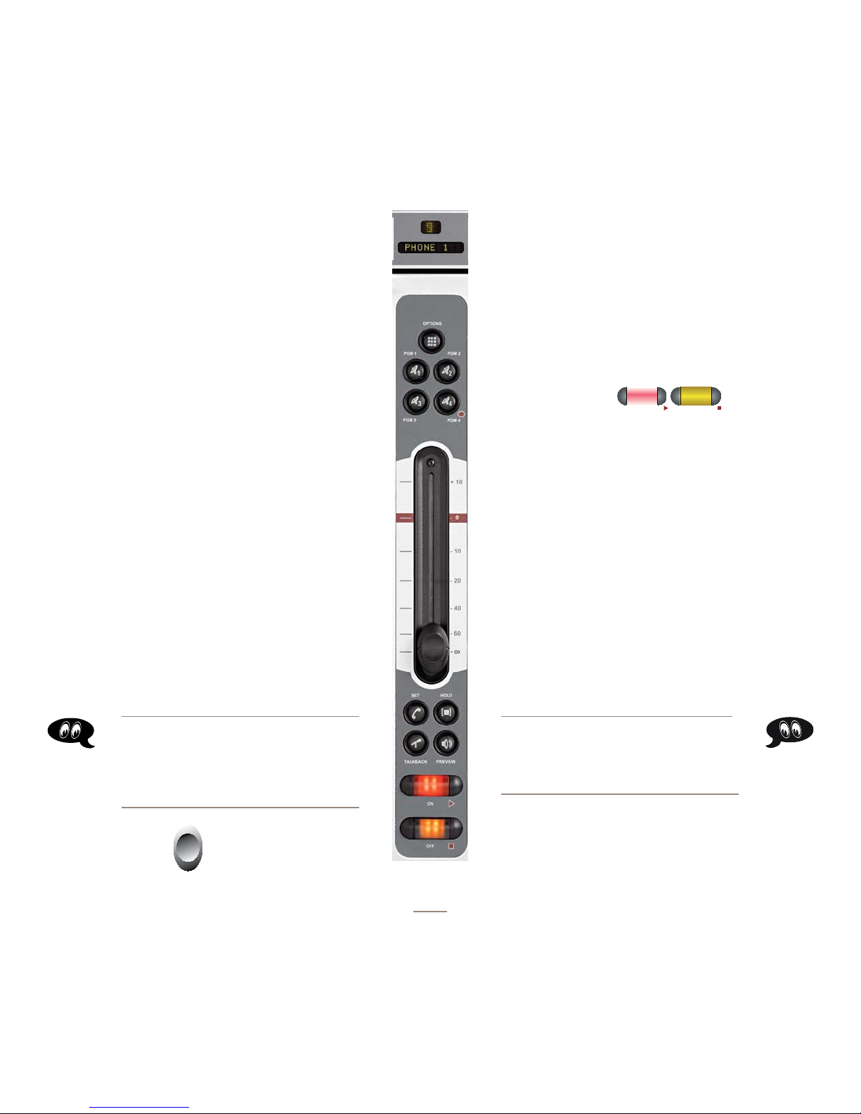
signs that channel to the Preview bus; pressing it again
removes the channel from Preview. To enable an op-
erator to quickly listen to various sources, the Preview
function is interlocked: pressing Preview on any chan-
nel will remove any other channel from Preview
mode.
If you want to preview multiple channels,
pressing and holding any Preview key disables
the interlock; other sources can be added to the
Preview mix by pressing them. Conversely, chan-
nels can be removed from a multiple Preview se-
lection by pressing and holding any lit Preview
key and deselecting the individual channels you
wish to remove from Preview. A momentary press
of any lit Preview key will remove all channels
from Preview.
The interlock option for Preview can be dis-
abled in any Show Profile’s Monitor section so
that users can gang preview sources without the
need to press and hold the preview button.
The audio from the Preview bus feeds any
speakers dedicated to Preview, and can also be
routed to the operator’s headphones if desired.
Preview speakers will be muted whenever the
board operator’s microphone is ON, or is assigned
to the Preview or Record buses.
fader up turns the channel on and sends logic com-
mands. In fader-start mode, the On and Off keys
act more as indicators of channel status; the On key
will not turn the channel on if the fader is at the bot-
tom of its travel.
In fader-normal mode, on/off status and
2.
start/stop commands follow the channel ON/
OFF buttons independent of fader position.
For information on how to switch between
fader-start and fader-normal modes, see the
Monitor Module Controls section later in this
chapter.
On and Off Keys
•
When the channel is in fader-normal mode
the On key ( u ) turns the channel on and the Off
key ( n ) turns it off. The channel On and Off
functions also provide logic (start and stop pulses,
monitor muting, etc.) appropriate to the selected
source.
If a control-room mic is assigned to a fader,
the CR monitors and Preview speakers will mute
when that fader is turned on. and when sources
are Previewed. If a fader is hosting a microphone
source, pressing the On button when the fader is
already on mutes the channel, providing a “cough”
function, until the button is released.
New Feature: If an operator presses Talk on
a fader to which a Phone source is assigned
and, while holding it, presses the Preview
button, both will latch on, makeing it easy to
have a hands-free off-line chat using the CR
Mic. Pushing either one clears both.
Fader
•
The fader controls the volume of the input
source. There are two modes for the fader: fader-
start and fader-normal:
When the channel is used in fader-start mode,
1.
pushing the fader all the way to the bottom of its
travel turns the module off, and sends appropriate
logic commands to source equipment. Moving the
New Feature: In fader-start mode, holding
the Off button while moving the fader up
disables the usual GPIO start command. The
On button may be later used to issue the
command.
4-Phone Module Channel Controls
Figure 4-2:
Phone Module
Fader Channel
©2008 Axia Audio — Rev. 3.0
ement fader module. But some fader modules
include special keys that provide extra functions
for certain types of sources. The 4-Phone Fader
Module (Figure 4-2) is one of these modules. If a normal
line source is assigned to a Phone Fader, the fader and
its controls operate exactly like a standard 4-Fader Mod-
ule (described in the previous section). But whan a Telos
You can assign any type of source to any El-
4: Element Operations • 43
Page 54
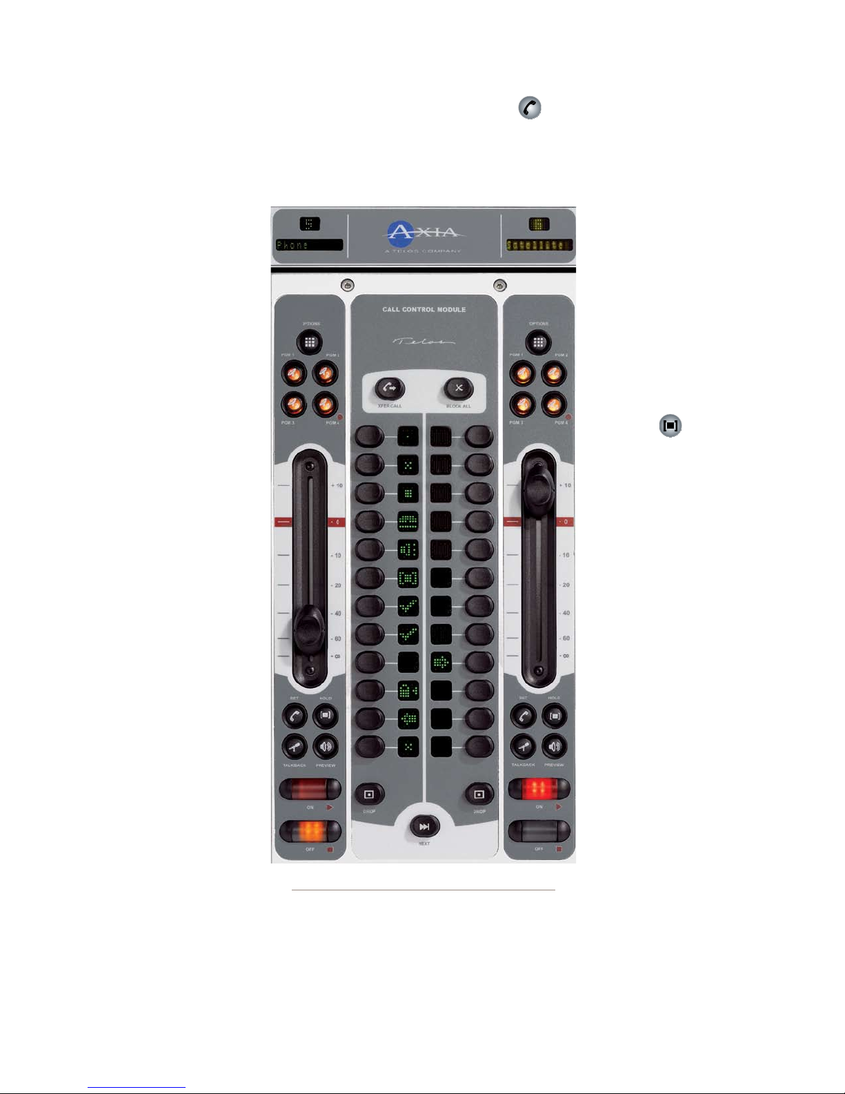
4: Element Operations • 44
telephone hybrid is assigned to one of these faders, extra
functionality is enabled.
Taking Calls
When controlling a Telos
phone system, the Status
Symbol box above the alpha
display indicates an avail-
able line by displaying a
single dot. A call ringing in
shows a “ringing” icon. It is
answered by pushing either
the On or Preview button. If
Preview is already on, tog-
gling to Off and then On an-
swers the call. When the call
is answered, an “up arrow”
Status Symbol icon displays.
Also, a window on Element‘s
screen will show call status
and incoming caller ID (if
available).
When the phone channel
is off and in Preview, press
Off to drop the call. When
the channel is on, press Off
once to put the caller on
hold; press twice to drop.
Making Calls
To dial out from the con-
sole, press any control key
(Off, On, Hold, Set, or Pre-
view) on a fader that hosts
a Phone source. This assigns
the Keypad on the Monitor
Module to that fader. Dialing
works like a mobile phone:
Figure 4-3:Call Controller + 2-Fader Phone Module
enter all digits, then press
the Enter (8 ) or Pound (#)
key to place the call. The Status Symbol icon above the
fader indicates first that a line is active and then that the
call is proceeding. The Element display screen will also
indicate the numbers dialed and call status.
Set Key
•
If you’re using certain Telos broadcast phone systems,
pressing the Set key transfers the phone line assigned
to that fader to a handset. These buttons are mutually
exclusive across all faders;
touching a Set key on any
Phone Fader switches the
handset to the line assigned
to that fader and cancels any
previous line selection. For
details on Telos phone sys-
tems that utilize the Set key,
please refer to Appendix D,
“Working With Phone Hy-
brids”.
Hold Key
•
Pressing Hold sends a
hold command to the con-
nected Telos phone system.
When connected to Europe-
an ISDN lines, a hold signal
is sent to the network. With
USA ISDN lines, no net-
work hold function is avail-
able, so the hybrid enters a
virtual hold state.
Call Controller + 2-
Fader Phone Module
Controls
This module (Figure 4-3)
works with Telos TWOx12,
Series 2101 and Nx12 multi-
line talk show systems. Its
features the hybrid controls
found on Telos talk show
controllers, flanked by two
faders. Typically, the left
fader is linked to the left
hybrid control, and the right
fader to the right hybrid control. For details on hybrid
control operation and description of Status Symbols
used, please refer to your Telos TWOx12, Series 2101 or
Nx12 Operator’s Manual.
©2008 Axia Audio — Rev. 3.0
Page 55
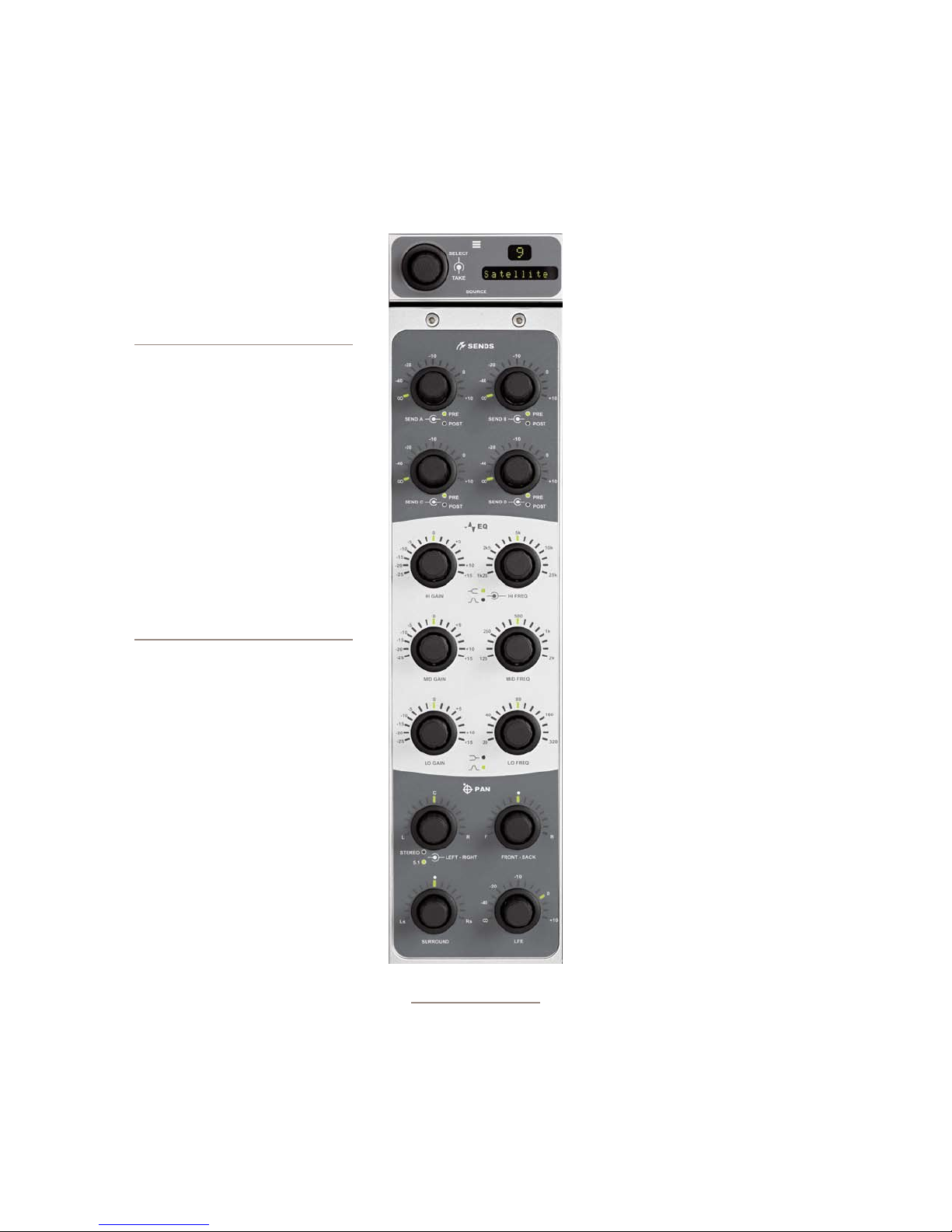
Production Module Controls
The Element Production Module gives production-
room gurus quick access to often-used EQ and posi-
tioning controls for each loaded source.
Its controls provide direct access to the
options presented in the EQ & DYNAM-
ICS options screens detailed later in this
chapter.
About Element EQ: Our EQ model
is three-band quasi-parametric. Controls are provided for center frequency
and boost/cut, with a unique SmartQ™
automatic bandwidth system.
SmartQ works by varying the Q of the
selected parametric band propor tional
to the amount of boost or cut you specify. A small amount of boost or cut will
affect a broader range of frequencies
for a warm, musically-pleasing effect.
As gain is increased the Q sharpens,
affecting a narrower range of frequencies for tighter control of target
bands. At aggressive cut levels, the
EQ becomes a tunable notch lter.
SmartQ keeps the EQ sounding natural at virtually all settings.
To activate the Production Module,
press the Options key on any fader strip.
The Production Module’s overbridge dis-
play will immediately mirror the number
of that fader and the name of the source
you’re adjusting EQ for.
Once the Production Module is active,
you can quickly adjust EQ using the con-
trols described below. To quickly set EQ
for multiple channels, rotate the SELECT
knob on the overbridge panel to choose
a different fader source, and press it to
TAKE that source.
AUX SEND A/B/C/D: These controls
•
allow you to send the output of the active fader to any
or all of the four Aux Send buses for ourboard audio
effects processing, custom IFB mixes, etc. Each Aux
Send control has 50 dB of adjustment range, from -∞
to +10dB. Rotating the knobs adjusts the send level;
Figure 4-4:Production Module
+ overbridge display
pushing the knob toggles the send between PRE-
and POST-FADER.
The three central pairs of knobs are EQ Controls:
•
HI GAIN/HI FREQ, MID GAIN/MID
FREQ and LO GAIN/LO FREQ.
The GAIN knobs provide 40 dB of adjust-
ment range for boost or cut of the three
parametric bands, from -25 dB to +15 dB.
The FREQ knobs each act slightly differ-
ently:
HIGH FREQ: Sets the active frequency
»
for high-band EQ. Pushing this knob
toggles the EQ model between Shelf
and Bandpass modes. If set to Shelf,
the HIGH FREQ knob determines the
top of the shelf. If set to Bandpass,
it sets the center frequency of the BP
filter (SmartQ determines the width of
the BP filter, as described above).
MID FREQ: Sets the center frequency
»
of the midrange parametric band.
LOW FREQ: Sets the center frequency
»
of the low parametric band. Pushing
this knob toggles the EQ model be-
tween Shelf and Bandpass modes.
If set to Shelf, the LOW FREQ knob
determines the top of the shelf. If set
to Bandpass, it sets the center fre-
quency of the BP filter
The four knobs at the bottom of the mod-
•
ule are the PAN controls.
The upper left knob PANs the sound
»
field left-to-right.
The FRONT-BACK knob moves the
»
soundfield front-to-rear (in 5.1 mode).
The SURROUND knob pans the rear
»
speakers left-to-right (in 5.1 mode).
The LFE knob adjusts the gain of the Low Fre-
»
quency Effects channel (in 5.1 mode).
4: Element Operations • 45
©2008 Axia Audio — Rev. 3.0
Page 56
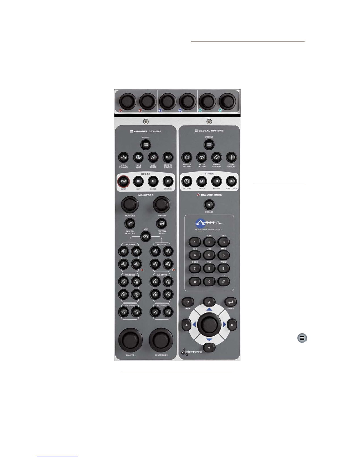
Standard Monitor Module Controls
The standard Monitor Module (Figure 4-5) contains
direct-access controls for all of Element’s options and
features. Constantly-used controls like headphone and
monitor selection and vol-
ume, plus command keys
for the on-screen timers,
controls for an external pro-
fanity delay unit, and a nu-
meric keypad for convenient
dialing of telephone systems
and codecs are included.
Nav Keys & Control Knob
Located at the bottom
right of the module is a
Control Knob surrounded
by a set of navigation keys
(Up, Down, Right and
Left), an Enter key (8
and a Help key (?). These
controls augment the Soft-
Knobs and provide another
way to navigate Element
option screens.
Operators can use the
directional keys to navigate
through on-screen lists, and
the Enter key to “take” a se-
lection. The Control Knob
can also be used to scroll
through on-screen lists.
),
Channel Jumping: If any fader is in Options
mode, you can “quick jump” to set options for other fader channels by pressing the Options key at
the top of their channel strips.
For example, if you need to change the Source
on several channels, select the rst channel us-
ing its Options key, and
then choose the Chan-
nel Options Source
key. The Source Selection list will appear onscreen. Once the source
reassignment is made,
simply press the Op-
tions key on the next
channel you want to assign a new source to; the
Source screen will remain active, and you’re
now adjusting settings
for the new channel.
The channel number is
displayed onscreen as
conrmation.
Placing a channel in Op-
tions mode lets you change
inputs, apply EQ, change
pan position, invert phase,
set Aux Send and Aux Re-
turn levels, and adjust mix-
minus settings for that chan-
nel. The Options displays
(Figure 4-6) give detailed
channel information. Both
the Element channel num-
ber (the physical fader posi-
tion, from left to right) and
the source assigned to that
channel are displayed for
confirmation.
Channel Options Section
These keys allow
the operator to custom-
ize the behaviour of indi-
vidual faders. The opera-
tor first presses the Options key atop the fader
s/he wishes to modify; the Channel Options box is dis-
played on Element’s screen (Figure 4-6), and the Chan-
nel Options keys then become active.
4: Element Operations • 46
Figure 4-5:Standard Monitor Module + Sof tKnobs
ly selected source alongside a list of available sources
Operators may select using the SoftKnobs or Nav Keys.
They can also preview a source before selecting it.
©2008 Axia Audio — Rev. 3.0
•
Source Key
Pressing Source dis-
plays the Source Selection
menu. The Source Selection
screen displays the current-
Page 57
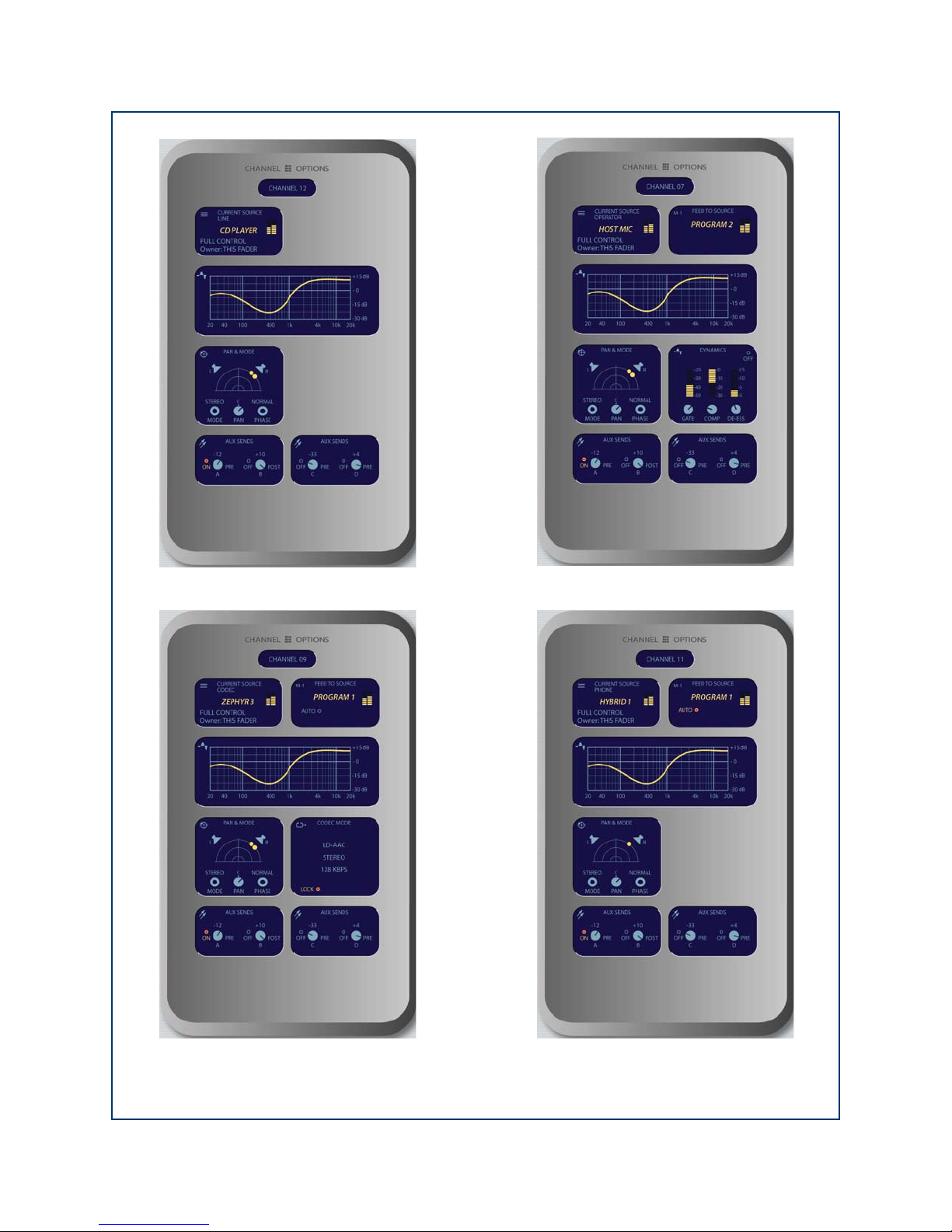
Figure 4-6: Channel Options screens. Information displayed dif fers based on the t ype of source currently assigned to the
active fader. Shown clockwise fr om top lef t: Line Source Channel Options screen, Mic Source Channel Options screen,
Phone Source Channel Options screen, Codec Sour ce Channel Options screen.
4: Element Operations • 47
©2008 Axia Audio — Rev. 3.0
Page 58
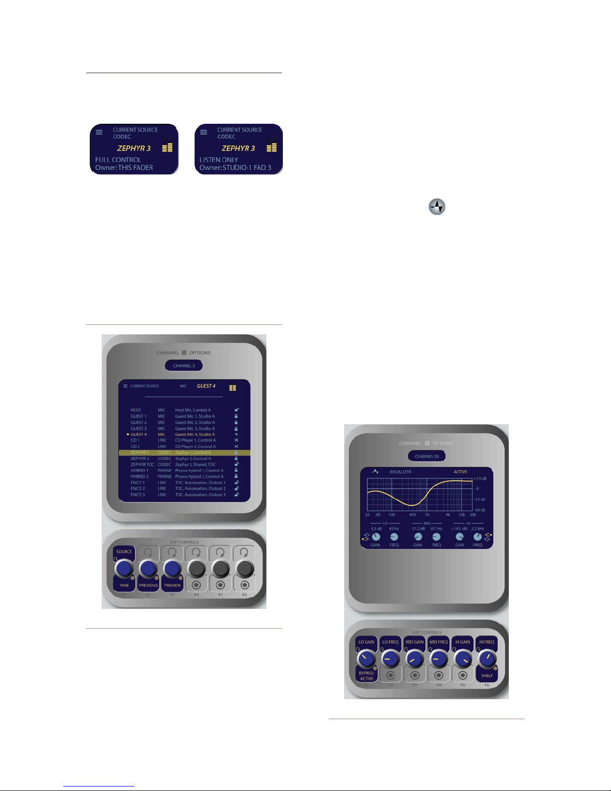
A Note About Source Sharing: Element’s
source sharing protocol keeps sources from
being controlled by more than one console at a
time.
If an operator tries to assign a source that’s
already in use on another console and has a
backfeed or logic control enabled, the ID box in
the Channel Options screen informs him that
he has “Listen Only” rights to the source (as
seen in the righthand box above) - no backfeed
will be sent from his console, and no machine
logic is tied to the fader’s ON/OFF keys.
If the source is not in use anywhere else, the
operator is informed that they have “Full Con-
trol” of the source (as shown in the lefthand
box above), and backfeed and logic operate
normally.
selection, press the
Previous
knob. the prior
source will be immediately reloaded to the fader.
Preview
»
allows you to hear the highlighted
source through the Preview speakers without
haveing to “take” it. Press and hold to listen; re-
lease to end the preview.
Pressing
»
Source
again returns to the Channel
Options screen.
EQ & Dynamics Key
•
This command allows three-band parametric equal-
ization to be applied to the selected audio source and,
if it is a mic source, to apply dynamics processing by
Omnia. Pressing the
EQ & Dynamics
key causes the
EQ
screen to appear; pressing it a second time displays the
Dynamics
screen, and pressing a third time exits.
When the
EQ
screen is displayed, a graphical rep-
resentation of the equalization curve is displayed as
the controls are adjusted. The screen also indicates the
amount of cut/boost applied, and the center frequency
of each band.
Lo Gain/Bypass/Active:
»
Rotating this Soft-
Figure 4-7: Sour ce menu screen.
»
Source/Take
: rotating this SoftKnob scrolls
through the available sources. Push to take.
»
Previous
: Whenever you “take” a new source,
your last source selection is held in memory.
Should you change your mind about the new
4: Element Operations • 48
source and wish to return to your previous source
Figure 4-8: EQ menu scr een.
©2008 Axia Audio — Rev. 3.0
Page 59
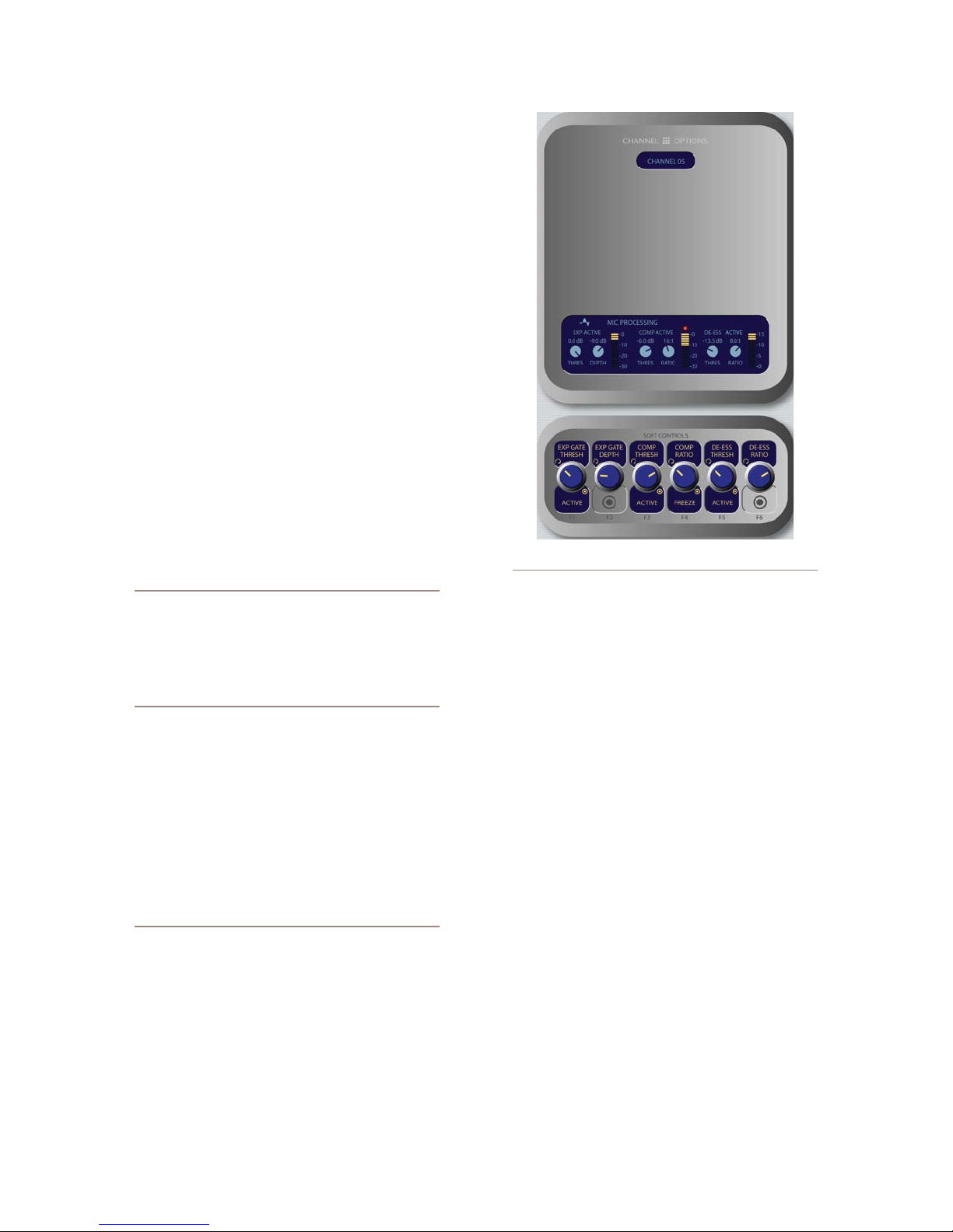
Knob adjusts the amount of gain or cut applied
to the low EQ band; note that the Shelf/Peak in-
dicator next to the onscreen control automatically
shifts to Peak mode when boost is applied, and
shifts to Shelf mode when cut is applied. Press-
ing this knob toggles EQ between Active and
Bypass.
Rotating the Lo Freq knob adjusts the center fre-
»
quency of the low EQ band (20 - 320 Hz).
Rotating the Mid Gain and Mid Freq SoftKnobs
»
adjust gain and center frequencies of the mid-
range EQ band (125 Hz - 2 kHz).
The Hi Gain knob adjusts the boost/cut of the
»
high frequency band (1.25 kHz - 20 kHz).
Hi Freq/Shelf/Peak: Rotating this SoftKnob
»
adjusts the center frequency of the high EQ band
(1 kHz - 16 kHz). Pushing this knob toggles the
high-band EQ method between Peak and Shelf
modes.
Pressing EQ & Dynamics again displays the Dy-
»
namics screen.
Note: High, Mid and Low band adjustments
provide up to 25 dB of cut and 15 dB of boost.
Element EQ features SmartQ™ automatic bandwidth system that varies the Q of the selected
parametric band to provide the most pleasing
EQ effect. For details on SmartQ, please refer
to Page 44 of this manual.
Dynamics controls are available if the selected
source is a Mic, Codec or Phone input. Pressing the Dy-
namics & EQ key twice invokes the Dynamics menu.
From here, you can add Gating, Compression and De-
essing to a microphone channel. Normally, these values
are part of a pre-set Show Profile; however, on-the-fly
control is provided for talent to make adjustments when
needed.
What is this stuff? Radio engineers don’t need
a lesson in dynamics processing, but for the benet of any jocks reading this, here’s a quick explanation of what these controls can do.
A Gate is a dynamics device whose function
is to remove unwanted audio material below a
certain threshold. A gain circuit is employed to
raise or lower the volume of the audio signal;
when the signal falls below a certain set threshold, the audio level drops down to a predetermined level. The reason they are called gates
Figure 4-9: Dynamics menu screen.
is because when they “close” it sounds as if
the audio has suddenly stopped, or has been
“gated.” You might use this on a mic channel to
eliminate background noise during times when
you’re not speaking.
Threshold settings determine at what level the
processor will begin working. For example, on
a compressor, when signal level exceeds the
threshold setting, it will be compressed; below
the threshold the signal will remain uncompressed. On a gate, threshold determines the
minimum input level required to cause the gate
to open up and pass signal; when input level
drops below the threshold, the gate will be closed
preventing signal from passing. Carefully setting
the threshold allows you to very specically control when processing is being applied to a signal.
Compression controls the dynamic range of an
audio signal. It generally reduces the volume of
very loud audio, helping to keep from “blowing
out” the mic channel with too much volume. It
can be used to make your mic channel sound
“fatter,” evening out the highs and lows of your
vocal pattern. It can also increase the overall
perceived fullness of your voice. Too much compression, however, can make your voice sound
hard and “squashed.” Use it sparingly!
To use compression, you must rst set your
threshold value (usually expressed in dB). When
the audio signal is louder than this threshold, its
gain is reduced. The amount of gain reduction
applied depends on the Compression Ratio
setting. For example, with a 2:1 ratio, for every
4: Element Operations • 49
©2008 Axia Audio — Rev. 3.0
Page 60
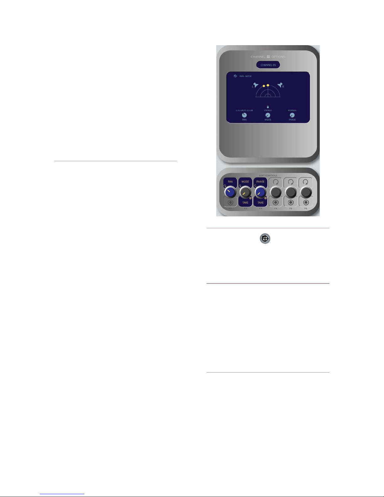
4: Element Operations • 50
2 decibels the input signal increases, the output
is allowed to increase only 1 decibel.
The Freeze Gate is used to prevent “suck-up”
of room noise during speech pauses. When active, gain is not increased by the compressor
when audio is absent. “Freeze” would be the
default, since it almost always improves results.
De-Essing is just what you think it is - a way to
electronically remove extra sibilance from your
mic channel. If your mic is particularly sensitive
to “s” and “th-” sounds and accentuates them
on-air, De-Essing helps reduce these sounds to
more manageable levels. As with compression,
too much de-essing will produce annoying and
unnatural results - you’ll wind up sounding like
you’re talking through a cotton sock! Stick to
small amounts to get the effect you want.
»
Rotating the Exp Gate Thresh/Bypass/Ac-
tive SoftKnob varies the level of signal thresh-
old needed for the Gate function to activate (be-
tween -50 and 0dB). Pushing this knob toggles
Dynamics between Active and Bypass states.
»
The Exp Gate Depth knob sets the amount of
gain reduction when audio level falls below the
Exp Gate Threshold value (adjustable between
-3 and 0dB).
»
Comp Thresh/Bypass/Active sets the upper
limit of the level at which the compressor will
begin to work (between -30 and 0dB). Pushing
the SoftKnob toggles between Active and By-
pass states.
»
Comp Ratio/Freeze/No Freeze sets the com-
pression ratio (variable between 1:1 and 16:1).
Pushing the SoftKnob activates and deactivates
the compressor’s Freeze Gate function. When
the Freeze function is active, a red “lamp” illu-
minates just above the Compression Ratio bar-
graph meter.
»
De-Ess Thresh/Bypass/Active sets the audio
level above which the de-esser will be engaged
(from -20 to 0dB). Pushing the SoftKnob toggles
between Active and Bypass states.
»
De-Ess Ratio sets the amount of sibilance re-
duction, in dB, that will be applied (adjustable
between 1:1 and 8:1).
»
Pressing the Dynamics & EQ key again will re-
turn you to the Channel Options screen.
Figure 4-10: Pan / Mode menu screen.
Pan & Mode Key
•
This function allows the operator to adjust the pan or
balance of the channel source and correct signal phase
errors.
It’s a Lock: If a “padlock” icon appears in any
options screen, that function is “locked out” in
the Source Prole and adjustments cannot be
made. In Figure 4-10, the padlock appears just
below the soundeld representation, above the
Mode indicator. The onscreen Mode SoftKnob
is also “grayed out” to show that this function
is unavailable.
Operators cannot “unlock” locked functions;
if you wish to make locked functions available,
simply modify the source prole to allow them
and when the source is reloaded to the console,
the padlock will have disappeared.
Pan/Balance: Rotating this SoftKnob adjusts
»
the the Pan setting for mono sources and the Bal-
ance setting for stereo sources.
Mode: If the selected source is in stereo and the
»
Source Profile for the selected source permits
it (see Chapter Two for information on Source
Profiles), rotating this control lets the board op
switch source audio between Stereo (discrete
©2008 Axia Audio — Rev. 3.0
Page 61
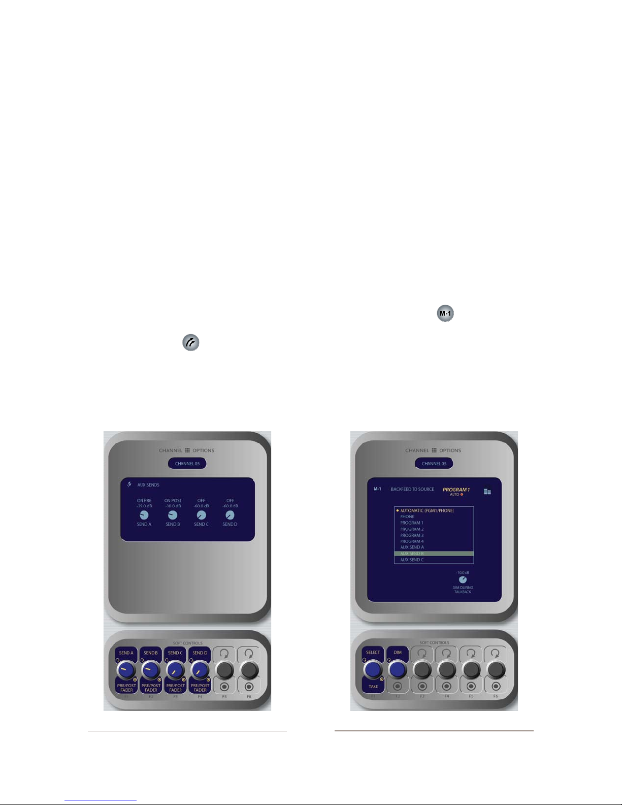
left/right), Left (left source channel fed to L/R
input), Right (right source channel fed to L/R
input) and Sum (left and right source channels
summed to mono and fed to L/R input). Push to
Take the new setting.
Phase: If the selected source is stereo, rotat-
»
ing this control lets the board op compensate for
out-of-phase audio sources. Normal is used for
in-phase sources; Inv Left inverts the phase of
the left input channel only, Inv Right inverts the
phase of the right input channel only, and Invert
Both reverses phase of both stereo channels.
If the selected source is in mono, the choices are
Normal and Invert only. Press to Take the new
setting.
Pressing Pan & Mode again returns to the Chan-
»
nel Options screen.
Aux Sends Key
»
Element has four stereo Aux buses that can be used
as utility buses for mixing, for constructing custom IFB
mixes, or as effects buses for production. Pressing this
key displays the Aux Sends screen.
Send A/B/C/D: Rotate these knobs to adjust the
»
level of the audio you’ll be sending to any or all
of the four Aux Send buses.
Pre/Post Fader: Pushing any of the four Send
»
SoftKnobs toggles the activity state of that par-
ticular Send. The state is indicated in the display
above.
On Pre sends the source assigned to the fader
*
to the selected Aux Send bus prior to having
its gain adjusted by the fader (fixed level).
On Post sends the source assigned to the fad-
*
er to the selected Aux Send bus after having
its gain adjusted by the fader (variable level).
Off sends no audio to the Aux Send bus.
*
Pressing Aux Sends again returns to the Chan-
»
nel Options screen.
Feed To Source Key
•
If the assigned source (i.e., a codec or phone hybrid)
has an associated backfeed or mix-minus, pressing this
key allows the board op to change the audio supplied
through the backfeed. This selection is normally pre-set
when a Source Profile is constructed (see Chapter Two,
“Configuring Inputs,” for information on Source Profiles),
but can be modified on-the-fly.
Figure 4-11: Aux Sends menu sc reen.
Figure 4-12: Feed to Source menu screen.
4: Element Operations • 51
©2008 Axia Audio — Rev. 3.0
Page 62
The Select/Take knob, when rotated, scrolls
»
through the list of available audio sources that
can supply backfeed or mix-minus.
Automatic backfeeds audio from the Phone
*
bus when the channel is Off, and audio from
the Program-1 bus when the channel is On,
with mix-minus if needed.
Phone backfeeds audio from the Phone bus,
*
with mix-minus if needed.
Program 1 - Program 4 backfeeds audio
*
from the selected Program bus, with mix-mi-
nus if needed.
Aux Send 1 - Aux Send 4 backfeeds audio
*
from the selected Auxiliary bus, with mix-
minus if needed.
About the PHONE and PROGRAM 4 buses:
Element ’s Program 4 mix bus is a special multipurpose bus that does several things at once to
make life easier for the operator.
Any source assigned to Program 4 also be fed
to the PHONE bus and sent to callers when the
channel is OFF and AUTO is selected as the
Feed To Source Mode. PHONE is an internal bus
which does not feed a separate output; instead,
it picks up the Program 4 audio pre-fader and
pre-On/Off and backfeeds them to an PHONE
sources.
Sources assigned to Program 4 are also sent to
the RECORD bus, a special xed-level output
that can be used to feed recording devices.
Rotating the Dim knob allows the operator to
»
adjust, in dB, the amount by which the studio
monitors are dimmed when this fader channel’s
Talkback key is pressed.
Pressing Feed to Source or Options a second
»
time exits this menu.
Monitor Section
This controls in this section provide direct operator
access to monitor selection and volume controls.
Monitor 1 Knob + Source Keys
•
This knob, at the bottom left of the Monitor section,
controls the selection and volume of the source heard
in the Monitor 1 speakers (typically the Control Room
monitors).
Rotate the knob to vary the gain of the Monitor
»
1 speakers.
Use the Direct Selection Keys in the column
»
directly above the Monitor 1 knob to send the
output of Program 1 - Program 4, Aux Send
A - Aux Send D, or the two External monitor
sources to the Monitor 1 speakers. These keys
light to denote the selected source.
You can listen to any frequently-used audio
»
stream in your facility instantly (such as a net-
work feed, off-the-air monitor or another studio’s
Program output) by assigning it to one of the two
External selector keys - like preset buttons on a
car radio.
Programming the External Monitor Selector keys: If you press and hold either of these
keys for ve seconds, a list of available audio
streams will pop up onscreen. You can then
scroll through this list and select the source you
want to hear in the monitors when that key is
pressed. Each External key is independently
programmable.
You can also pre-program the source assigned
to these keys when you construct or capture
Show Proles, using the options available on the
Monitor page of the Show Prole setup menu.
Delay Section
These keys can be used to provide from-the-board
control of an external profanity delay unit using one of
Element’s GPIO ports (refer to Chapter 3: Configuring
GPIO for instructions on GPIO setup).
The keys provide for remote activation of Dump,
Exit, Pause and Engage functions, respectively.
4: Element Operations • 52
Headphone Knob + Source Keys
•
This knob, at the bottom right of the Monitor section,
controls the selection and volume of the source heard in
the board operator’s headphones.
Rotate to vary the gain of the Headphone feed.
»
Use the Direct Selection Keys in the column di-
»
A - Aux Send D, or the two External monitor
©2008 Axia Audio — Rev. 3.0
rectly above the Headphones knob to send the
output of Program 1 - Program 4, Aux Send
Page 63
sources to the headphones. These keys light to
denote the selected source.
Press and hold either of the External selector
»
keys to display and select from a list of available
audio streams to monitor on these keys.
Link Key
•
This key toggles the Monitor 1 / Headphone source
Link function. When active, a change to the Monitor 1
source automagically selects that source for the Head-
phone feed, and vice versa. The Link key illuminates
when this function is active.
Monitor 2 Knob
•
This knob, at the top left of the Monitor section, con-
trols the selection and volume of the source heard in the
Monitor 2 speakers (typically Studio or News booth
monitors).
Rotate to vary the Monitor 2 speaker gain.
»
Push the knob to see an on-screen display of
»
sources that can be assigned to the Monitor 2
feed. Rotate to highlight the desired source, and
push again to “take”.
Talk To Monitor 2 Key
•
The board operator can push and hold this key to
talk to the talent listening to the Monitor 2 feed. While
the key is depressed, audio from the Control Room mic
channel is fed, pre-fader, to the Monitor 2 speakers
and headphones (if used). Releasing the key ends the
talkback function.
Preview speakers. The Preview To HP key illuminates
when this function is active.
There are three different Preview to HP modes; the
current mode is indicated by an annunciator on the Ele-
ment display screen just below the headphone selection
tally.
Off: When Preview to HP is off, the selector key
»
is unlit. No preview audio will be heard in the
board-op’s HP path.
On: Pressing the Preview to HP key once from
»
the Off state sends preview audio, when present,
into both sides of the operator’s headphone feed,
overriding the Monitor audio. The Preview to
HP key is now lit.
Auto: Pressing the Preview to HP key a sec-
»
ond time toggles Auto mode. In this mode, audio
from the Preview channel overrides the Head-
phone Monitor selection in the left headphone
channel only. Program audio is still present in
the right channel of the operator’s headphones.
Global Options Section
The Global Options keys are used to load Show
Profiles and to customize Monitor, Meter, Aux Sends/
Returns and Fader settings.
Prole Key
•
Pressing this key allows the board operator to browse
and select from the list of saved Show Profiles, custom
surface configurations that can be loaded as needed to
reconfigure Element for different shows and talent.
Preview Knob
•
This knob, at the top right of the Monitor section,
controls the volume of the source heard in the Preview
(cue) speakers. Rotate the knob to vary the gain of the
Preview speakers.
Preview To HP Key
•
This key toggles the Preview To Headphone func-
tion. When active, this function sends Preview audio
to the board operator’s headphones. When inactive, au-
dio from the Preview bus is heard exclusively in the
As soon as you “take” a new show profile, Element
begins loading it. During the profile loading process, a
status line reads Loading (Show Profile Name) to
inform the operator of the operation in progress.
LOADING A NEW SOURCE WHILE ANOTHER
SOURCE IS STILL ACTIVE: Element will nev-
er interrupt an active source in order to load a
new one.
Let’s say that the operator has a satellite
feed assigned to Channel 10, and this source
is currently on-the-air (assigned to Program-
1, fader up, channel On). The board op loads
©2008 Axia Audio — Rev. 3.0
4: Element Operations • 53
Page 64
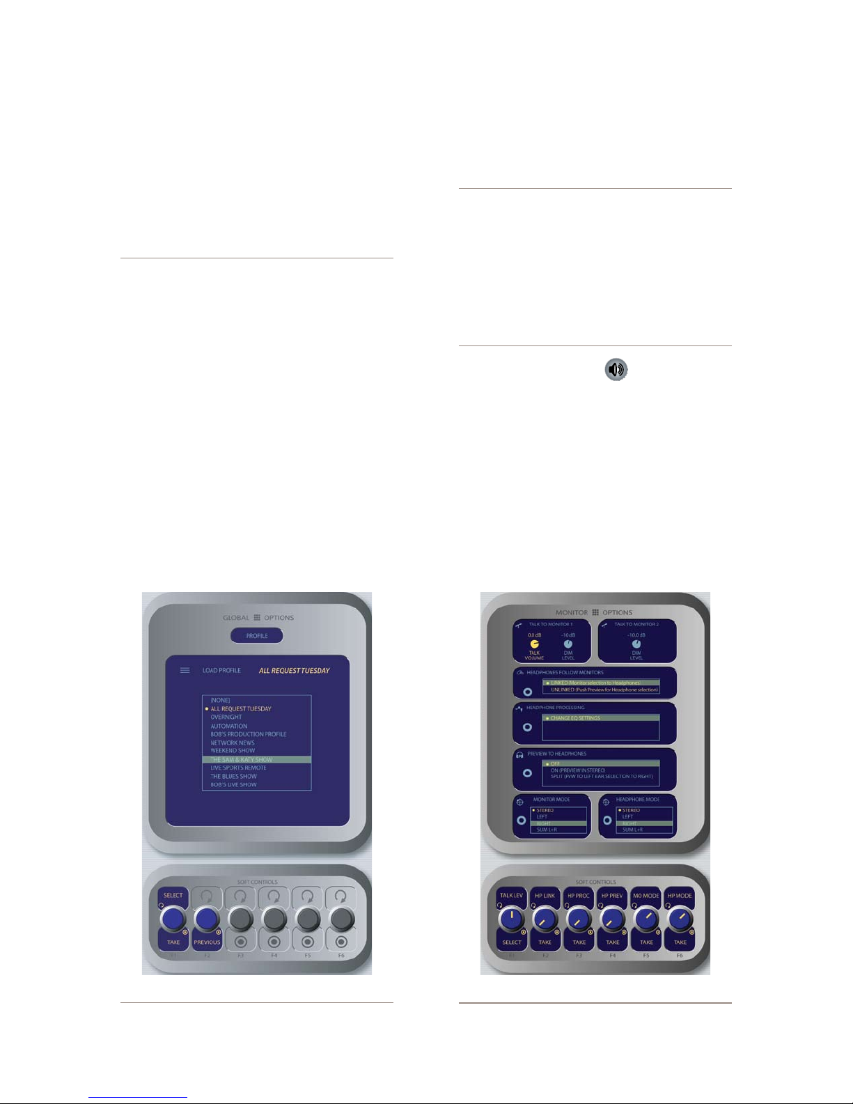
a new Show Prole to ready Element for
the next show; the Show Prole he’s loading has a CD player assigned to Channel
10. Obviously, there’s a conict.
Instead of blindly changing the channel source
and interrupting audio that’s on-the-air, Element
queues the new source. When the board op is
nished with the satellite feed, he turns the
channel Off and the CD player automatically
loads.
Along with selecting a new Show Prole to load,
users can reload the currently active profile, resetting
the board to a “nominal” state if they wish to return
to their normal configuration after making on-the-fly
changes.
Select / Take: Rotate this knob to scroll through
»
the on-screen list of available Show Profiles. Push
the knob to “take” the new Show Profile.
Previous: When you load a new Show Profile,
»
Element remembers the previously loaded Pro-
file until you exit the Show Profile screen. The
Previous command functions as a “speed key,”
highlighting the previously assigned source in
the source list and allowing the operator to re-
turn to it should they change their mind. Press
to “take.”
DON’T PANIC! Element is full of options intended to make life on-air easier and more intuitive
for today’s talent. However, it’s possible for talent not yet familiar with the way Element works
to “get lost” in the option settings.
Pressing and holding the Prole key for ve
seconds instantly clears changes made to the
current Show Prole, resetting the Show Prole’s default settings. All is well, and your jock
once again knows where his towel is.
•
Monitor Options Key
Pressing this key reveals all sorts of neat options re-
lating to Monitor and Headphone behavior. The Monitor
Options screen is shown in Figure 4-14.
»
Pushing the TALK LEV SoftKnob selects be-
tween adjusting the levels of the Monitor 1 Talk
To and Dim levels and the Monitor 2 Dim level.
The active function is highlighted in yellow on
the screen. Turn the knob to adjust the values of
4: Element Operations • 54
Figure 4-13: Show Prole selection screen.
Figure 4-14: Monitor Options menu screen.
©2008 Axia Audio — Rev. 3.0
Page 65
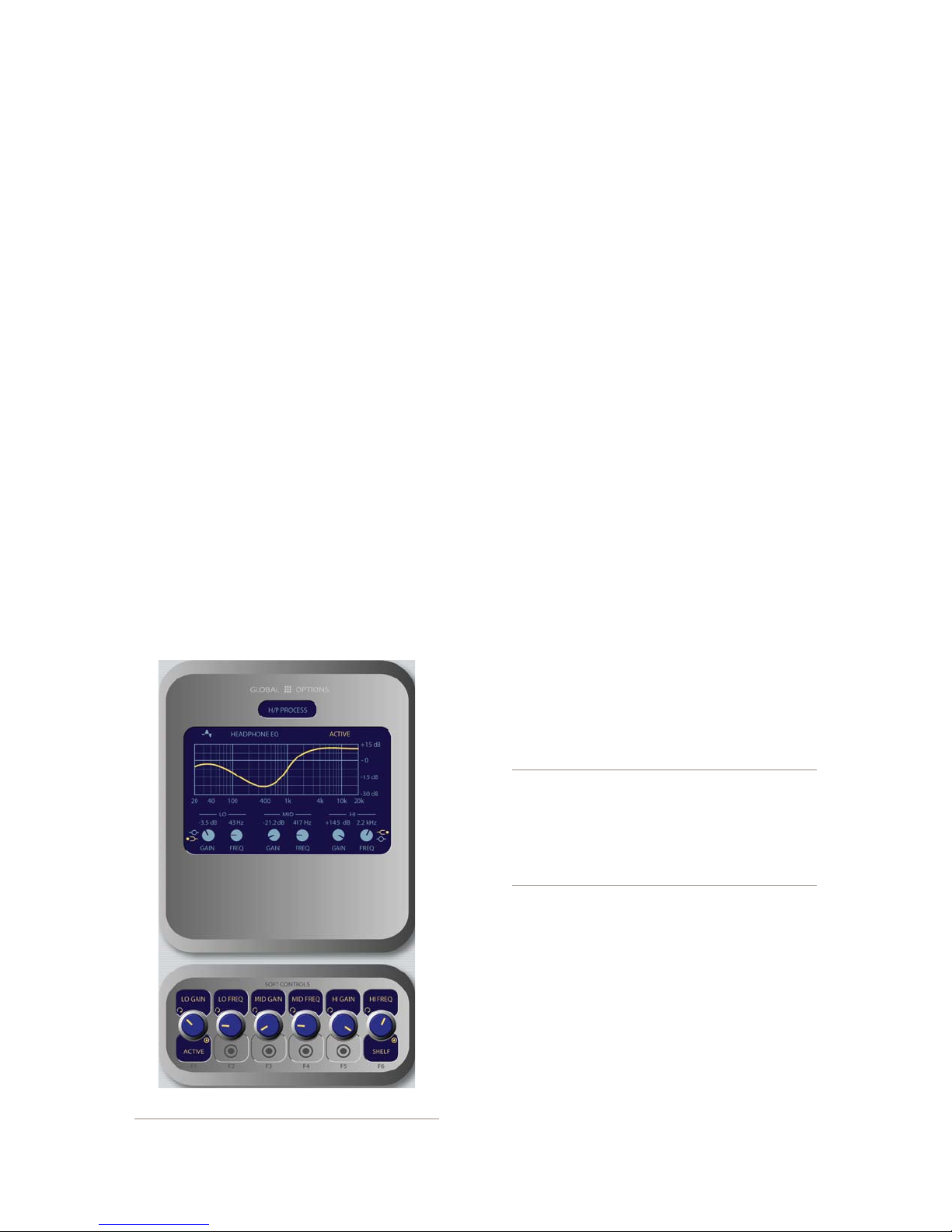
these settings.
Rotate the HP LINK knob to choose whether
»
the headphone source will follow the Monitor
1 source selection. Push the knob to Take your
selection.
Linked means that Headphone and Monitor
*
1 selections will mirror each other; making a
selecton from one bank of keys on the Moni-
tor Module will automatically choose the
same source on the other bank.
Unlinked allows Monitor 1 and Headphone
*
sources to be selected independently of each
other.
The H/P PROC knob allows the board op to turn
»
Headphone Processing on and off, define how it
operates if active, and change Headphone Process-
ing settings. Pushing the HP Proc knob selects
Change Settings onscreen and takes the operator
to the H/P Process screen shown in Figure 4-15.
In this screen, the operator is presented with
a graphical representation of the EQ curve ap-
plied to the headphone channel. Talent can then
apply three-band parametric equalization to his
or her headphone channel, and select headphone
dynamics processing. The screen indicates the
amount of cut/boost applied, and the center fre-
quency of each band as well as a list of Omnia
processing presets.
Lo Gain/Bypass/Active: Rotating this Soft-
»
Knob adjusts the amount of gain or cut applied
to the low EQ band. Pressing this knob toggles
EQ between Active and Bypass. Note that the
EQ mode for this band automatically changes
to Peak mode when boost is applied, and Shelf
mode when cut is applied.
Rotating the Lo Freq knob adjusts the center
*
frequency of the low EQ band (20 - 320 Hz).
Rotating the Mid Gain and Mid Freq Soft-
*
Knobs adjust gain and center frequencies of
the midrange EQ band (125 Hz - 2 kHz).
The Hi Gain knob adjusts the boost/cut of the
*
high frequency band (1.25 kHz - 20 kHz).
Hi Freq/Shelf/Peak: Rotating this Soft-
*
Knob adjusts the center frequency of the high
EQ band (1 kHz - 16 kHz). Pushing this knob
toggles the high-band EQ method between
Peak and Shelf modes.
Press the Monitor Options key to return to
*
the previous menu.
Figure 4-15: H/P Process settings.
Note: High, Mid and Low band adjustments
provide up to 25 dB of cut and 15 dB of boost.
Element EQ features SmartQ™ automatic bandwidth system that varies the Q of the selected
parametric band to provide the most pleasing
EQ effect. For details on SmartQ, please refer
to Page 44 of this manual.
The H/P PREV knob controls whether audio
»
*
*
©2008 Axia Audio — Rev. 3.0
from the Preview bus can be fed to the board
op’s headphones, and if so, in what manner. Note
that operators can also press the Preview to
HP key on Element’s Monitor Module to toggle
through these settings. Rotating this knob selects
from the following options:
Off: The operator will not hear Preview au-
dio in the headphone channel.
On: audio from the Preview channel over-
4: Element Operations • 55
Page 66
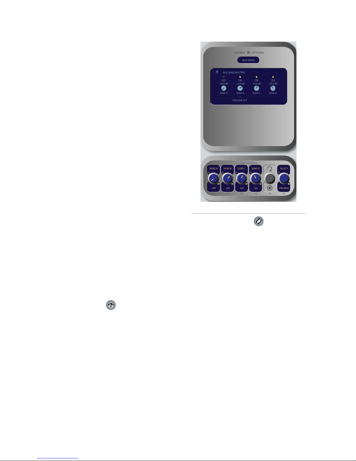
4: Element Operations • 56
rides the Headphone Monitor selection and
is sent to both the left and right channels of
the operator’s headphones.
Split: Audio from the Preview channel
*
overrides the Headphone Monitor selection
in the left headphone channel only. Program
audio is still present in the right channel of
the operator’s headphones.
After making a selection, push the knob to
*
Take the new value.
MO MODE knob: Rotate to select from the fol-
»
lowing options.
Stereo: The selected source will be present-
*
ed in stereo on the Monitor speakers.
Left: The left channel of the selected source
*
will be presented in both Monitor speakers.
Right: The right channel of the selected
*
source will be presented in both Monitor
speakers.
Sum L+R: Both channels of the selected
*
source will be summed and presented to both
Monitor speakers.
After making a selection, push the knob to Take
the new value.
H/P MODE knob: Works like the MO MODE
»
knob described above, but affects the board op-
erator’s Headphone channel. Pressing Monitor
Options or Options exits this menu.
Meter Options Key
•
Pressing this key opens the Meters screen, where
you can choose whether the far-right on-screen meter
bars will display levels for the PGM-4 bus or for the
source feeding the Monitor 1.
Dedicated means the meter will be slaved to the
»
PGM-4 bus.
Follow Monitors means the meter will show
»
levels for any source assigned to Monitor 1.
Figure 4-16: Aux Sends menu screen.
Sends & Returns Key
•
This key affects global settings for the master send
and return levels of the four stereo Aux Send and two
stereo Aux Return buses. The outputs can be turned
On or Off and can be sent to the preview speakers and
headphones (if preview is enabled in headphones).
Element’s Aux buses can be used as utility buses for
mixing, for constructing custom IFB mixes, or as effects
buses for production. Pressing the Sends & Returns
key once takes you to the Aux Sends Master screen
(Figure 4-16); pressing it twice displays the Aux Re-
turns Master screen (Figure 4-17), and pressing a third
time exits the menu.
Aux Sends Master screen options:
The Send A/B/C/D SoftKnobs, when rotated,
»
set the Master Send Gain for each Aux Send bus.
Pushing any of these knobs toggles that individu-
al Aux Send Master On or Off.
The Select/Preview knob allows you to hear
»
any of the four Aux Send mixes in the Preview
channel. Push to preview; releasing to end the
preview.
©2008 Axia Audio — Rev. 3.0
Page 67
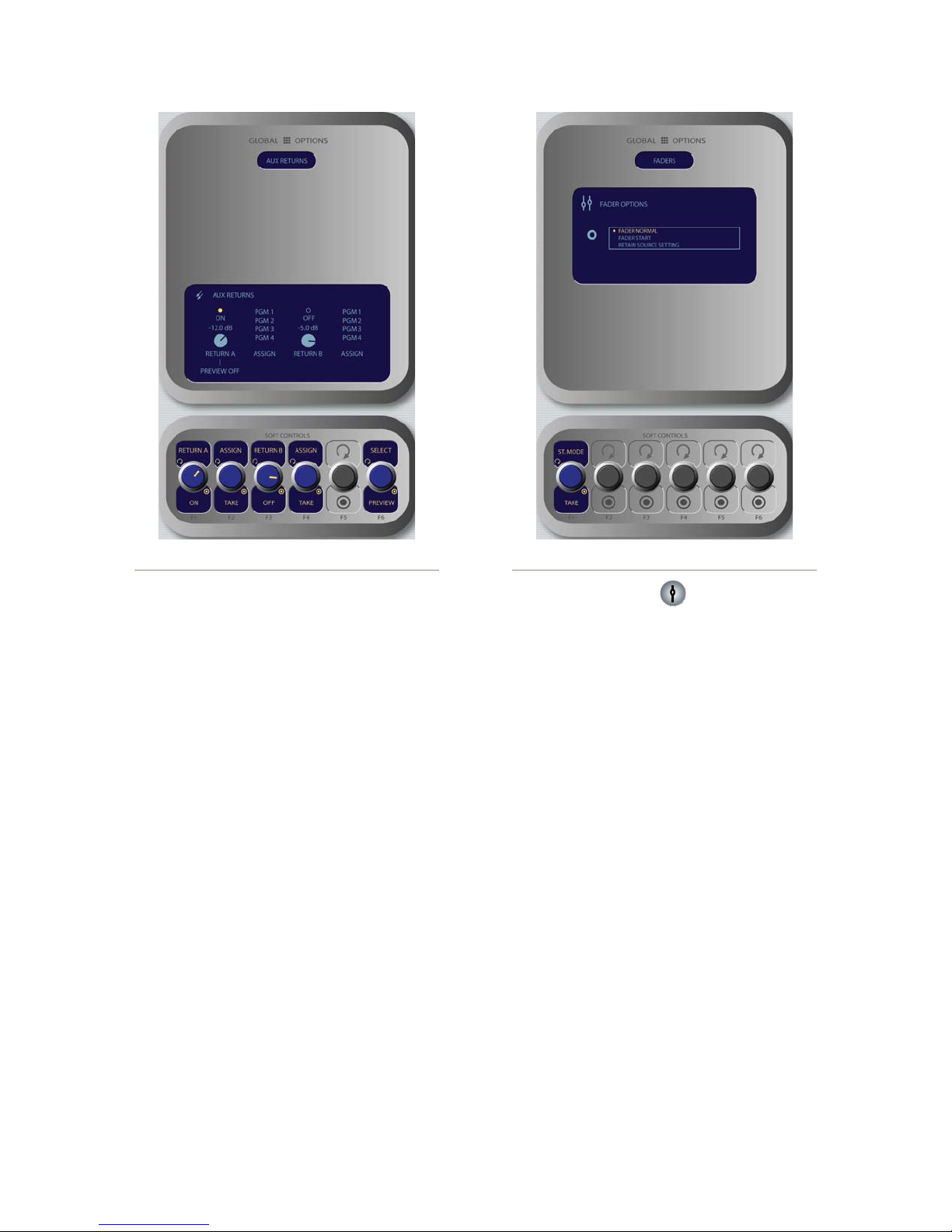
Figure 4-18: Fader Options menu scr een.Figure 4-17: Aux Returns menu screen.
Aux Returns Master screen options:
Rotate the Return A/On/Off SoftKnob to set
»
the audio level of Aux Return A. Push the knob
to toggle Aux Return A On or Off.
Rotate the adjacent Assign/Take knob to choose
»
which of the four Program buses to assign the
output of Aux Return A. Push the knob to Take
the assginment.
Rotate the Return B/On/Off SoftKnob to set
»
the audio level of Aux Return B. Push the knob
to toggle Aux Return B On or Off.
Rotate the adjacent Assign/Take knob to choose
»
which of the four Program buses to assign the
output of Aux Return B. Push the knob to Take
the assginment.
Rotating the Select/Preview knob allows you
»
to select either of the Aux Return mixes for au-
ditioning in the Preview channel; the on-screen
menu indicates which Aux Send is selected.
Push the knob to preview; release it to end the
preview.
Press the Sends & Returns key one more time to
exit the menu.
Fader Options Key
•
Element supports fader-normal and European-style
fader-start channel activation methods. Fader style can
be set either globally, or on a per-fader basis.
Each input’s Source Profile contains a Fader Mode
choice, which lets you set the behavior of individual fad-
ers. The Global Fader Options menu allows you to set
the behavior of the entire console.
In default Normal operation, Element conforms to
the US method of requiring talent to manually turn the
channel on and off. Fader Star t mode follows the Euro-
pean convention of activating the channel and associated
machine logic when the fader is raised from ∞.
Rotate the St. Mode/Take SoftKnob to choose fad-
er modes:
Fader Normal: Selects the US convention.
»
Fader Start: Selects the Euro convention.
»
Retain Source Setting: Each individual fader
»
uses the settings specified in its Source Profile.
Press the Fader Options key again to exit.
4: Element Operations • 57
©2008 Axia Audio — Rev. 3.0
Page 68
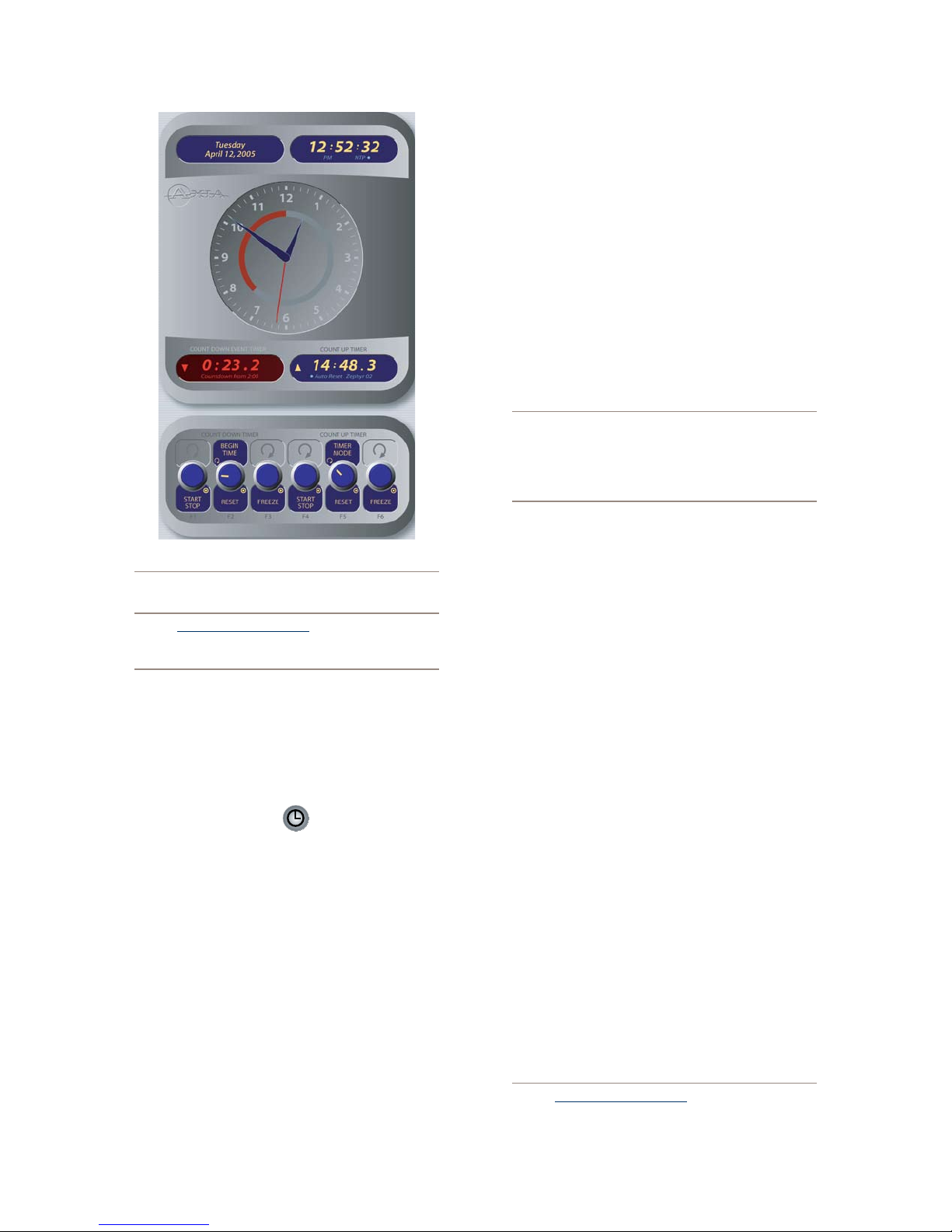
4: Element Operations • 58
Figure 4-19: Timer menu.
Note: Pressing and holding the Fader Options
key for ve seconds enters the IP Address
Book discussed in Chapter 1.
Timer Section
The Timer control keys operate Element’s onscreen
event and countdown timers, and allow users to set op-
tions determining the behavior of these timers.
Timer Options Key
•
Pressing the Timer Options key opens the Timer
Menu (Figure 4-19). This menu allows users to adjust
how the onscreen timers behave. Note that the Soft-
Knobs are divided into two sections: Countdown Timer
and Count Up Timer.
The Countdown timer is useful for counting
»
down to network joins, top-of-hour IDs, and oth-
er events which require exact timing. The Count-
down timer is started, stopped and reset manu-
ally using the controls displayed when the Timer
Options key is pressed. To use:
Rotate the SoftKnob marked Begin Time/
*
Reset to set the interval from which the
countdown will begin. As you rotate, small
numbers below the red counter onscreen will
inform you of the new countdown interval.
Press the Begin Time/Reset knob to set the
*
new time you’ve dialed in.
Press the Start/Stop knob to begin or end
*
the countdown.
Pressing Freeze holds the on-screen Timer
*
display so you may take note of it; the timer
continues to count while the display is frozen,
and a second press of the Freeze again dis-
plays the running elapsed time counter.
“Look at me!!” During the last 60 seconds of the
countdown, the inner ring of Element’s onscreen
analog clock will turn red and diminish as time
passes, providing the operator with a visual cue
to how much time is left until zero.
The Count Up Timer is an event timer with three
•
modes, which can be set to start/stop/reset either au-
tomatically or manually. Using Source Profiles, you
can determine whether individual sources will start
or stop this timer automatically; the onscreen con-
trols described below allow the operator to override
or modify those settings.
Rotate the Timer Mode SoftKnob to choose how
»
the event timer will operate.
Choose Manual to start, stop and reset the
*
timer by hand using the controls displayed
when the Timer Options key is pressed.
Choose Auto-Reset and the timer will au-
*
tomatically reset to zero and begin counting
whenever a fader whose source starts the
timer is turned On.
Choose Auto-Add to have the timer count
*
up when a designated source’s fader is turned
On and stop counting when that source is
turned Off. In this mode, the timer will not
reset to zero when it is started.
Pressing the Timer Options key again exits this
menu.
Note: Pressing and holding the Timer Options
Key opens the Clock & Timer Options Menu
©2008 Axia Audio — Rev. 3.0
Page 69
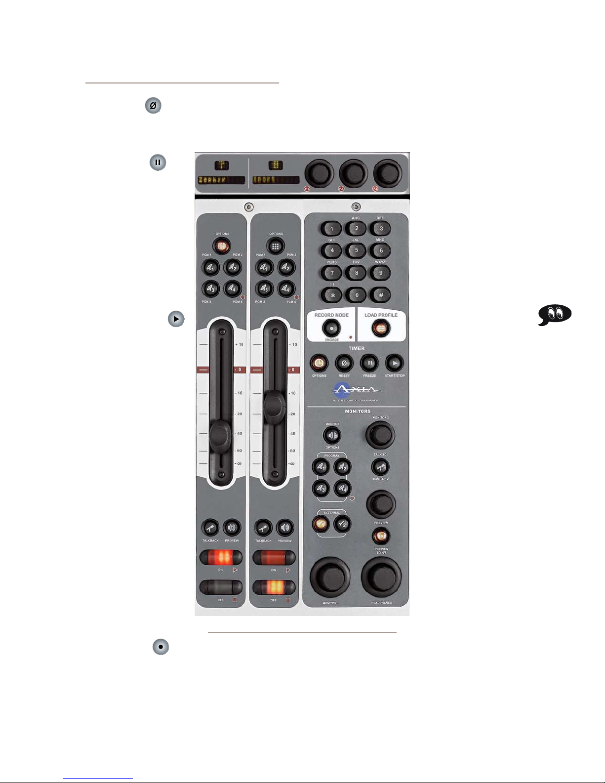
discussed in Chapter 1.
“Magic Key” Sequences for Standard Monitor Module
Reset Key:
•
Pressing this key resets Element’s Count Up Timer
to zero.
Freeze Key:
•
Pressing Freeze holds
the on-screen Timer display
so you may take note of it;
the timer continues to count
while the display is frozen,
and a second press of the
Freeze again displays the
running elapsed time coun-
ter.
Start/Stop Key:
•
If the Count Up Timer
is not running, pressing this
starts the count. If the timer
is running, pressing this key
stops the countdown and re-
tains the last displayed timer
interval.
Record Mode Section
Element’s Record Mode
is a special “one-touch”
mode which can be set to au-
tomatically start a designat-
ed record device so that tal-
ent can record a phone call
or remote interview with a
single button-press. Record
Mode can be enabled or dis-
abled for each Show Prole
(see Chapter 5, “Show Pro-
files”, for details).
Engage Key:
•
Figure 4-20:Monitor + 2-Fader Module + SoftKnobs
Press this key to put Element into Record Mode.
Pressing this button activates a pre-determined record-
ing device. Pressing the key a second time deactivates
Record Mode and stops the recorder.
The list of “Magic Key” sequences for the Standard
Monitor Module are:
IP Address Book: Press and hold the Fader Op -
•
tions key for 5 seconds.
Clock & Timer Settings:
•
Press and hold the Timer
Options key for 5 seconds.
Capture Mode: Press and
•
hold the Help key for 5 sec-
onds.
Test Mode: Press and hold
•
the Help and Right Arrow
keys for 5 seconds.
Monitor + 2-Fader
Module Controls
The Monitor + 2-Fader
Module (Figure 4-20) al-
lows users to customize their
console design, adding two
full-fuction faders at the cost
of some direct-access con-
trol keys in the Monitor sec-
tion. No flexibility has been
sacrificed, however; all the
functions provided by the
Standard Monitor Module
are present, but are accessed
differently. Controls for all
of Element’s options and
features are accessed via on-
screen menus with the aid of
SoftKnobs; constantly-used
controls like headphone and
monitor selection and vol-
ume, plus command keys
for the on-screen timers and
a numeric keypad for convenient dialing of telephone
systems and codecs are included. Since there are less
physical controls present on the Monitor + 2-Fader Mod-
ule than on the Standard Monitor Module, changes are
accomplished using the module’s SoftKnobs.
4: Element Operations • 59
©2008 Axia Audio — Rev. 3.0
Page 70
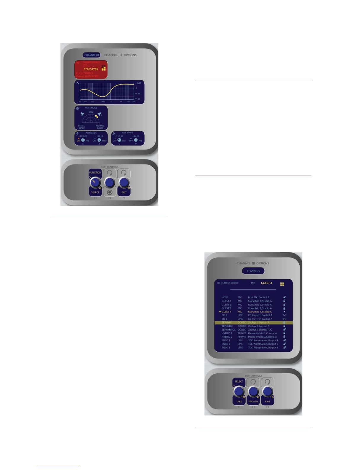
Figure 4-21: Channel Options Screen
Channel Options Controls
These controls allow the operator to custom-
ize the behaviour of individual faders. The op-
erator first presses the Options key atop the fader
s/he wishes to modify; the Channel Options box is dis-
played on Element’s screen (Figure 4-21), and the Soft-
Knobs become active.
Placing a channel in Options mode lets you change
inputs, apply EQ, change pan position, invert phase, set
Aux Send and Aux Return levels, and adjust mix-minus
settings for that channel. The Options displays (Figure
4-6) give detailed channel information. Both the Ele-
ment channel number (the physical fader position, from
left to right) and the source assigned to that channel are
displayed for confirmation.
takes you to the Source Selection screen.
»
Pressing the Exit knob returns you to Element’s
main display screen.
Channel Jumping: If any fader is in Options
mode, you can “quick jump” to set options for other fader channels by pressing the Options key at
the top of their channel strips.
For example, if you need to change the Source
on several channels, select the rst channel using its Options key, and then choose the Chan-
nel Options Source box. The Source Selection
list will appear on-screen. Once the source reassignment is made, simply press the Options
key on the next channel you want to assign a
new source to; the Source screen will remain
active, and you’re now adjusting settings for the
new channel. The channel number is displayed
onscreen as conrmation.
•
Source Selection Controls
Pressing Select when the Source box is highlight-
ed displays the Source Selection menu, which displays
the currently selected source alongside a list of available
sources operators may select using the SoftKnobs. They
can also preview a source before selecting it.
Figure 4-21 shows the Channel Options screen that’s
displayed when any fader’s Options key is pressed, with
the functions of the SoftKnobs shown below:
Rotating the Function/Select knob selects the
»
options you can modify, highlighting the current
function in red. Pressing this knob allows you
to modify the selected item; i.e., pressing when
4: Element Operations • 60
the Source box is highlighted (as in Figure 4-21)
Figure 4-22: Source menu screen.
©2008 Axia Audio — Rev. 3.0
Page 71
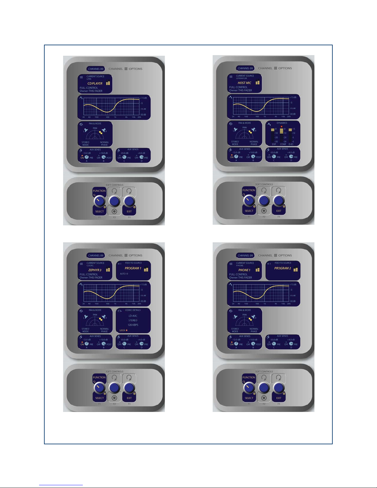
Figure 4-23: Channel Options screens for the Monitor + 2-Fader Module. Information displayed differs based on the type
of source currently assigned to the ac tive fader. Clockwise from top left: Line Source Channel Options screen, Mic
Source Channel Options screen, Phone Source Channel Options screen, Codec Source Channel Options screen.
4: Element Operations • 61
©2008 Axia Audio — Rev. 3.0
Page 72
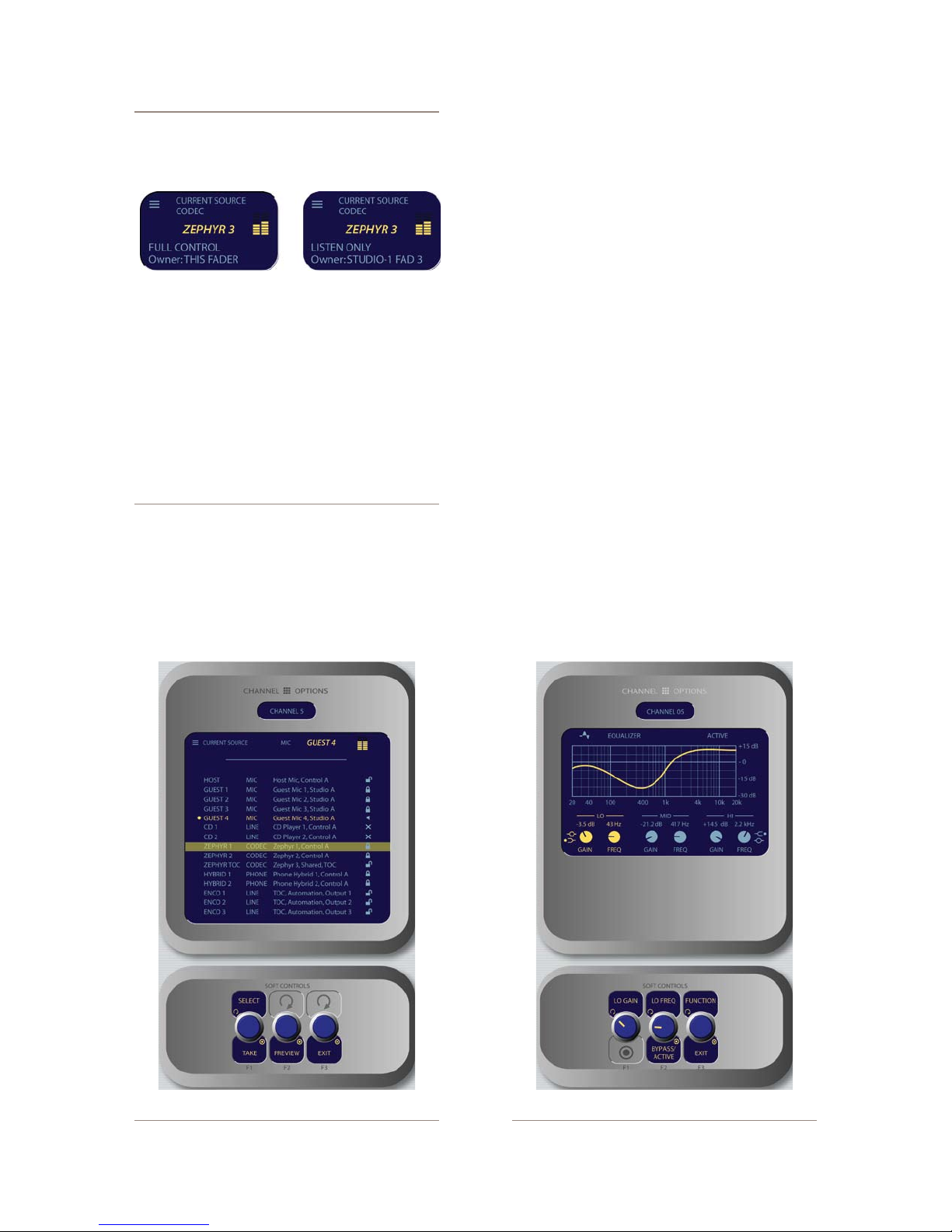
A Note About Source Sharing: Element’s
source sharing protocol keeps sources from
being controlled by more than one console at a
time.
If an operator tries to assign a source that’s
already in use on another console and has a
backfeed or logic control enabled, the ID box in
the Channel Options screen informs him that
he has “Listen Only” rights to the source (as
seen in the righthand box above) - no backfeed
will be sent from his console, and no machine
logic is tied to the fader’s ON/OFF keys.
If the source is not in use anywhere else, the
operator is informed that they have “Full Con-
trol” of the source (as shown in the lefthand
box above), and backfeed and logic operate
normally.
»
Select/Take
: rotating this SoftKnob scrolls
through the available sources. Push to take.
»
Preview
allows you to hear the highlighted
source through the Preview speakers without
haveing to “take” it. Press and hold to listen; re-
lease to end the preview.
Pressing the
»
Exit
Soft Knob returns you to the
Channel Options screen.
EQ Controls
•
Press the
is highlighted to adjust three-band parametric equaliza-
tion for the selected audio source. When the
Select
SoftKnob when the
EQ Curve
EQ
screen
box
is displayed, a graphical representation of the equaliza-
tion curve is displayed as the controls are adjusted. The
screen also indicates the amount of cut/boost applied,
and the center frequency of each band.
Rotate the
»
the
Function/Exit
Lo, Mid
SoftKnob to highlight
or Hi band knobs shown onscreen.
Notice that the left and center SoftKnob labels
change to display
Mid Freq
Function
The leftmost SoftKnob is the
»
and
knob.
to adjust the amount of
Lo Gain/Lo Freq, Mid Gain/
Hi Gain/Hi Freq
as you rotate the
Gain
control; rotate
gain or cut applied to the
selected band.
Note that when you adjust Lo Gain, the Shelf/
*
Peak indicator next to the onscreen control
4: Element Operations • 62
Figure 4-22: Source menu screen. Figure 4-23: EQ menu screen.
©2008 Axia Audio — Rev. 3.0
Page 73
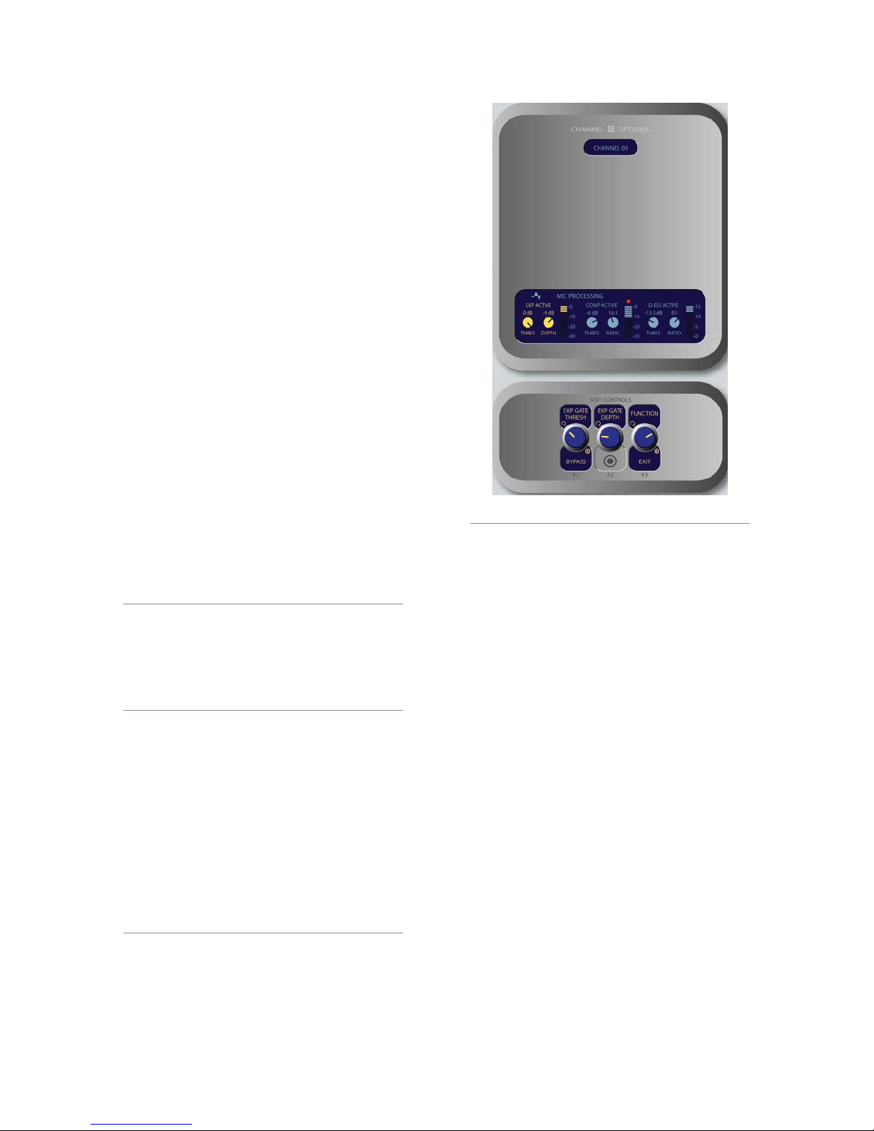
automatically shifts to Peak mode when boost
is applied, and shifts to Shelf mode when cut
is applied.
Note that when you select the Hi band, the la-
*
bel below the Gain control displays Hi Peak
or Hi Shelf, depending on which mode has
been selected. Push the knob to toggle be-
tween the two modes.
The center SoftKnob is the Freq control and
»
adjusts the center frequency of the selected EQ
band.
In Lo Freq mode, rotating the knob adjusts
*
the center frequency of the low EQ band (25
- 400 Hz).
In Mid Freq mode, rotating the knob adjusts
*
the center frequency of the midrange EQ
band (100 Hz - 1 kHz).
In Hi Gain mode, the knob adjusts the boost/
*
cut of the high frequency band.
Pressing the center SoftKnob toggles EQ be-
tween Active and Bypass.
Pressing the Function/Exit SoftKnob
»
returns
you to the Channel Options screen.
Note: High, Mid and Low band adjustments
provide up to 25 dB of cut and 15 dB of boost.
Element EQ features SmartQ™ automatic bandwidth system that varies the Q of the selected
parametric band to provide the most pleasing
EQ effect. For details on SmartQ, please refer
to Page 44 of this manual.
Dynamics Controls
•
Dynamics controls are available if the selected
source is a Mic, Codec or Phone input. Pressing the Se-
lect SoftKnob when the Dynamics box is highlighted
allows you to adjust Gating, Compression and De-es-
sing for a microphone channel. Normally, these values
are part of a pre-set Show Profile; however, on-the-fly
control is provided for talent to make adjustments when
needed.
What is this stuff? Radio engineers don’t need
a lesson in dynamics processing, but for the benet of any jocks reading this, here’s a quick explanation of what these controls can do.
A Gate is a dynamics device whose function
Figure 4-24: Dynamics menu screen.
is to remove unwanted audio material below a
certain threshold. A gain circuit is employed to
raise or lower the volume of the audio signal;
when the signal falls below a certain set threshold, the audio level drops down to a predetermined level. The reason they are called gates
is because when they “close” it sounds as if
the audio has suddenly stopped, or has been
“gated.” You might use this on a mic channel to
eliminate background noise during times when
you’re not speaking.
Threshold settings determine at what level the
processor will begin working. For example, on
a compressor, when signal level exceeds the
threshold setting, it will be compressed; below
the threshold the signal will remain uncompressed. On a gate, threshold determines the
minimum input level required to cause the gate
to open up and pass signal; when input level
drops below the threshold, the gate will be closed
preventing signal from passing. Carefully setting
the threshold allows you to very specically control when processing is being applied to a signal.
Compression controls the dynamic range of an
audio signal. It generally reduces the volume of
very loud audio, helping to keep from “blowing
out” the mic channel with too much volume. It
can be used to make your mic channel sound
“fatter,” evening out the highs and lows of your
vocal pattern. It can also increase the overall
perceived fullness of your voice. Too much compression, however, can make your voice sound
hard and “squashed.” Use it sparingly!
4: Element Operations • 63
©2008 Axia Audio — Rev. 3.0
Page 74
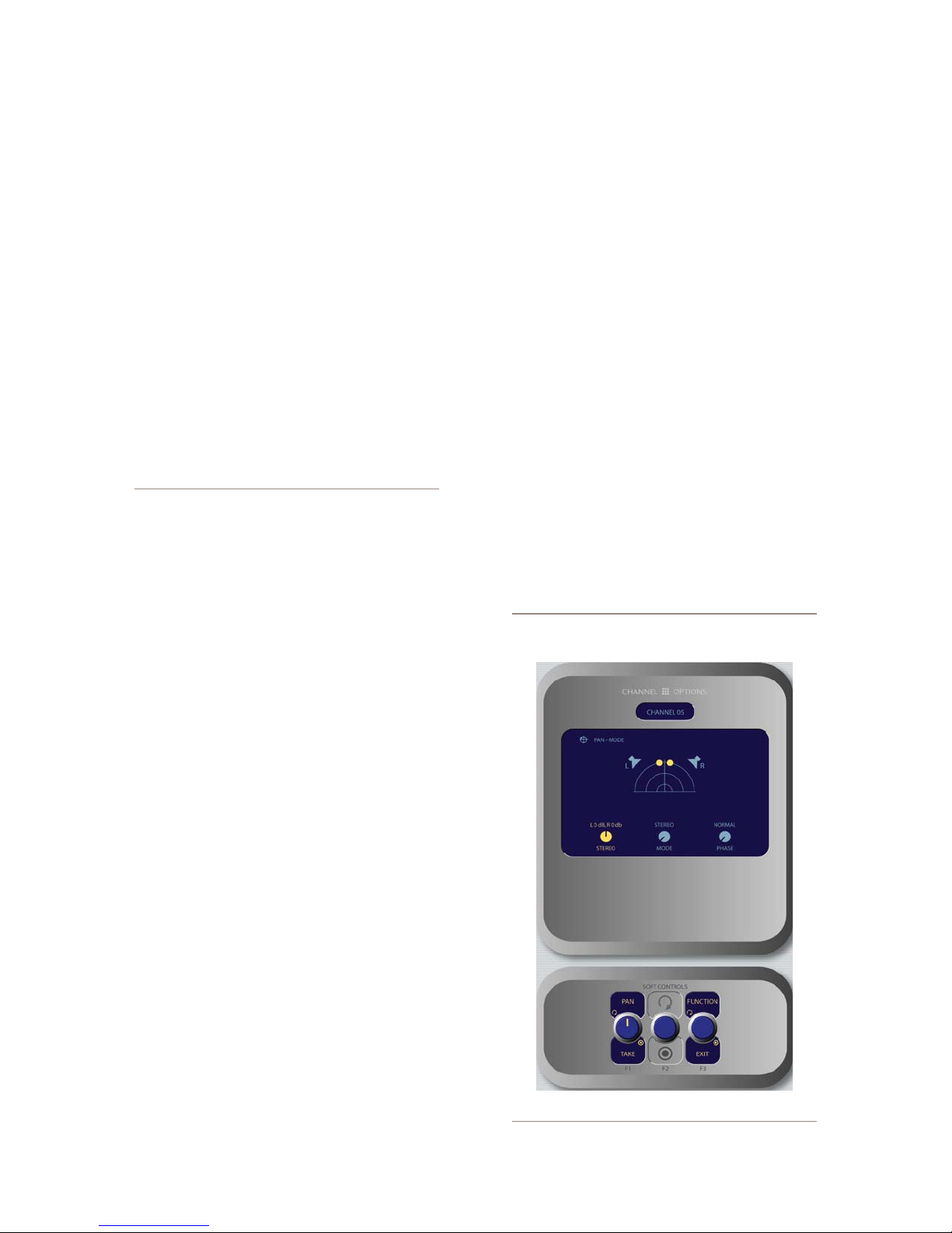
4: Element Operations • 64
To use compression, you must rst set your
threshold value (usually expressed in dB). When
the audio signal is louder than this threshold, its
gain is reduced. The amount of gain reduction
applied depends on the Compression Ratio
setting. For example, with a 2:1 ratio, for every
2 decibels the input signal increases, the output
is allowed to increase only 1 decibel.
The Freeze Gate is used to prevent “suck-up”
of room noise during speech pauses. When active, gain is not increased by the compressor
when audio is absent. “Freeze” would be the
default, since it almost always improves results.
De-Essing is just what you think it is - a way to
electronically remove extra sibilance from your
mic channel. If your mic is particularly sensitive
to “s” and “th-” sounds and accentuates them
on-air, De-Essing helps reduce these sounds to
more manageable levels. As with compression,
too much de-essing will produce annoying and
unnatural results - you’ll wind up sounding like
you’re talking through a cotton sock! Stick to
small amounts to get the effect you want.
»
Rotate the Function/Exit SoftKnob to highlight
the Exp (Expansion), Comp (Compression) or
De-Ess sections of the onscreen display. Note
that the labels above and below the left and cen-
ter SoftKnobs change based upon which section
is highlighted.
»
When the Expansion controls are active:
*
Rotating the Exp Thresh/Active/Bypass
SoftKnob varies the level of signal thresh-
old needed for the Gate function to activate
(between -50 and 0dB). Pushing this knob
toggles Dynamics between Active and By-
pass states.
*
The Exp Depth knob sets the amount of gain
reduction when audio level falls below the
Exp Gate Threshold value (adjustable be-
tween -3 and 0dB).
»
When the Compression controls are active:
*
Rotating the Comp Thresh/Bypass/Active
sets the upper limit of the level at which the
compressor will begin to work (between -30
and 0dB). Pushing the SoftKnob toggles be-
tween Active and Bypass states.
*
Comp Ratio/Freeze/No Freeze sets the
compression ratio (variable between 1:1 and
16:1). Pushing the SoftKnob activates and
deactivates the compressor’s Freeze Gate
function. When the Freeze function is active,
a red “lamp” illuminates just above the Com-
pression Ratio bargraph meter.
When the De-Ess controls are active:
»
Rotating the De-Ess Thresh/Bypass/Ac-
*
tive knob sets the audio level above which
the de-esser will be engaged (from -20 to
0dB). Pushing the SoftKnob toggles between
Active and Bypass states.
Rotating the De-Ess Ratio knob sets the
*
amount of sibilance reduction, in dB, that
will be applied (adjustable between 1:1 and
8:1).
Pressing the Function/Exit SoftKnob
»
returns
you to the Channel Options screen.
Pan & Mode Controls
•
Pressing the Select SoftKnob when the Pan &
Mode box is highlighted allows the operator to adjust
the pan or balance of the channel source and correct sig-
nal phase errors.
It’s a Lock: If a “padlock” icon appears in any
options screen, that function is “locked out” in
Figure 4-25: Pan & Mode menu screen.
©2008 Axia Audio — Rev. 3.0
Page 75
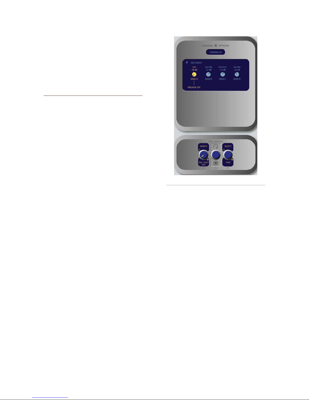
the Source Prole and adjustments cannot be
made. In Figure 4-10, the padlock appears just
below the soundeld representation, above the
Mode indicator. The onscreen Mode SoftKnob
is also “grayed out” to show that this function
is unavailable.
Operators cannot “unlock” locked functions;
if you wish to make locked functions available,
simply modify the source prole to allow them
and when the source is reloaded to the console,
the padlock will have disappeared.
»
Rotating the Function/Exit knob selects be-
tween Pan, Mode and Phase controls. The
active control is highlighted onscreen, and the
labels of the SoftKnobs change depending on
which function is active.
*
When the Pan/Balance mode is active, ro-
tating the SoftKnob adjusts the the Pan set-
ting for mono sources and the Balance setting
for stereo sources. Push the knob to Take
your new settings.
*
When the Mode mode is active, rotating the
SoftKnob lets the board op switch source au-
dio between Stereo (discrete left/right), Left
(left source channel fed to L/R input), Right
(right source channel fed to L/R input) and
Sum (left and right source channels summed
to mono and fed to L/R input). Push to Take
the new setting.
»
When the Phase mode is active:
*
If the selected source is stereo, rotating this
control lets the board op compensate for out-
of-phase audio sources. Normal is used for
in-phase sources; Inv Left inverts the phase
of the left input channel only, Inv Right in-
verts the phase of the right input channel only,
and Invert Both reverses phase of both ste-
reo channels. Press to Take the new setting.
*
If the selected source is in mono, the choices
are Normal and Invert only. Press to Take
the new setting.
»
Pressing the Function/Exit SoftKnob
returns
you to the Channel Options screen.
•
Aux Sends Controls
Element has four stereo Aux buses that can be used
as utility buses for mixing, for constructing custom
Figure 4-26: Aux Sends menu screen.
IFB mixes, or as effects buses for production. Pressing
the Select SoftKnob when the Aux Sends boxes are
highlighted takes the operator to the Aux Sends control
screen.
Rotating the Select/Exit knob selects between
»
Aux Send A, B, C & D. The active control is
highlighted onscreen, and the labels of the Soft-
Knobs change depending on which Send is ac-
tive.
Send A/B/C/D / Pre/Post Fader:
»
Rotate this knob to adjust the level of the
*
audio you’ll be sending to the selected Aux
Send bus.
Pushing the Knob to toggle the activity state
*
of the selected Send. The state is indicated in
the onscreen display above.
On Pre sends the source assigned to the
›
fader to the selected Aux Send bus prior
to having its gain adjusted by the fader
(fixed level).
On Post sends the source assigned to the
›
fader to the selected Aux Send bus after
having its gain adjusted by the fader (vari-
able level).
4: Element Operations • 65
©2008 Axia Audio — Rev. 3.0
Page 76
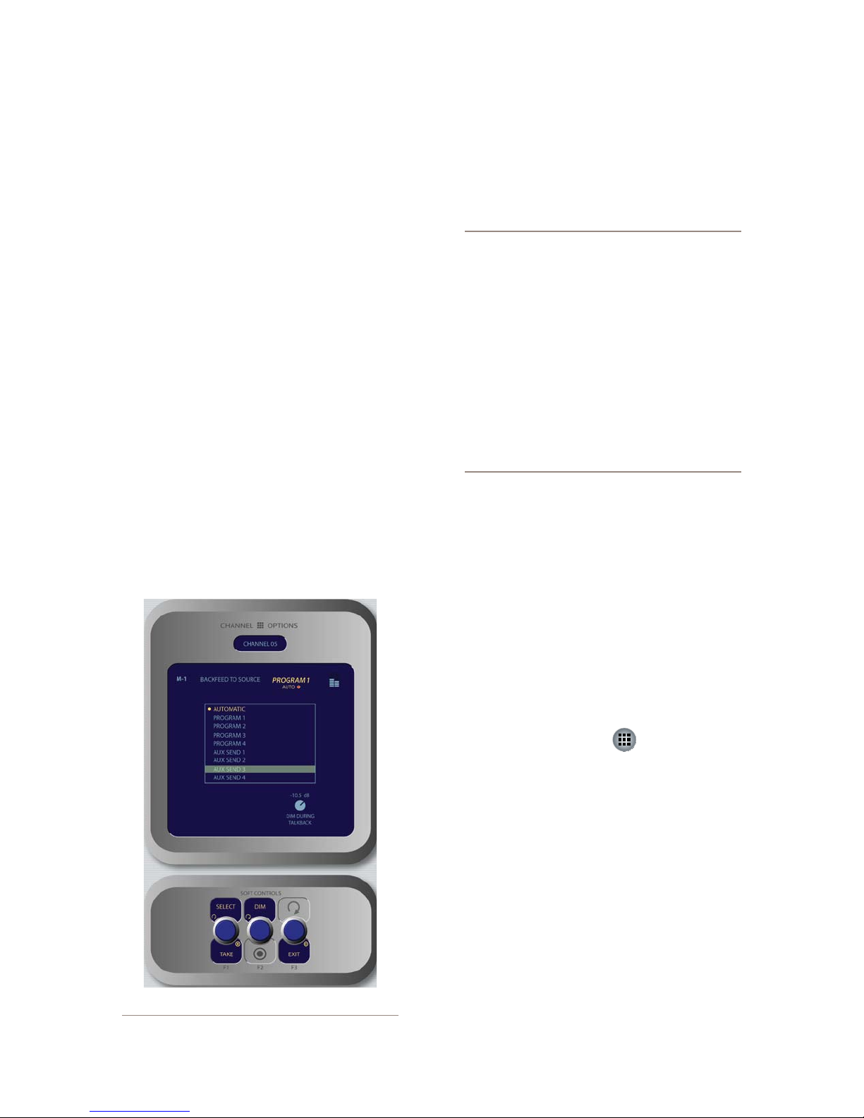
Off sends no audio to the Aux Send bus.
›
Pressing the Function/Exit SoftKnob
»
returns
you to the Channel Options screen.
Feed To Source Controls
•
If the assigned source (i.e., a codec or phone hybrid)
has an associated backfeed or mix-minus, Pressing the
Select SoftKnob when the Feed To Source box is
highlighted takes the operator to the Feed To Source
control screen. This selection is normally pre-set when a
Source Profile is constructed (see Chapter Two, “Config-
uring Inputs,” for information on Source Profiles), but
can be modified on-the-fly.
The Select/Take knob, when rotated, scrolls
»
through the list of available audio sources that
can supply backfeed or mix-minus. Press to Take
the highlighted source. Your choices are as fol-
lows:
Auto backfeeds audio from the Phone bus
*
when the channel is Off, and audio from the
Program-1 bus when the channel is On, with
mix-minus if needed.
Phone backfeeds audio from the Phone bus,
*
with mix-minus if needed.
Program 1 - Program 4 backfeeds audio
*
from the selected Program bus, with mix-mi-
nus if needed.
Aux Send 1 - Aux Send 4 backfeeds audio
*
from the selected Auxiliary bus, with mix-
minus if needed.
About the PHONE and PROGRAM 4 buses:
Element ’s Program 4 mix bus is a special multipurpose bus that does several things at once to
make life easier for the operator.
Any source assigned to Program 4 also be fed
to the PHONE bus and sent to callers when the
channel is OFF and AUTO is selected as the
Feed To Source Mode. PHONE is an internal bus
which does not feed a separate output; instead,
it picks up the Program 4 audio pre-fader and
pre-On/Off and backfeeds them to an PHONE
sources.
Sources assigned to Program 4 are also sent to
the RECORD bus, a special xed-level output
that can be used to feed recording devices.
Rotating the Dim knob allows the operator to
»
adjust, in dB, the amount by which the studio
monitors are dimmed when this fader channel’s
Talkback key is pressed.
Pressing the Exit SoftKnob
»
returns you to the
Channel Options screen.
4: Element Operations • 66
Figure 4-27: Feed to Source menu scr een.
Monitor Section
This controls in this section provide direct operator
access to monitor selection and volume controls.
Monitor Options Key
•
This key lets the operator access many options re-
lating to Monitor and Headphone behavior. There are
two different Monitor Options screen; the first is shown
when the key is initially pressed, and a second is display
when the key is pressed another time.
The first Monitor Options screen is shown in Fig-
ure 4-28:
Rotating the Function/Exit SoftKnob high-
»
lights the different control boxes onscreen, mak-
©2008 Axia Audio — Rev. 3.0
ing the highlighted control active. Labels on the
other SoftKnobs change depending on context.
Page 77
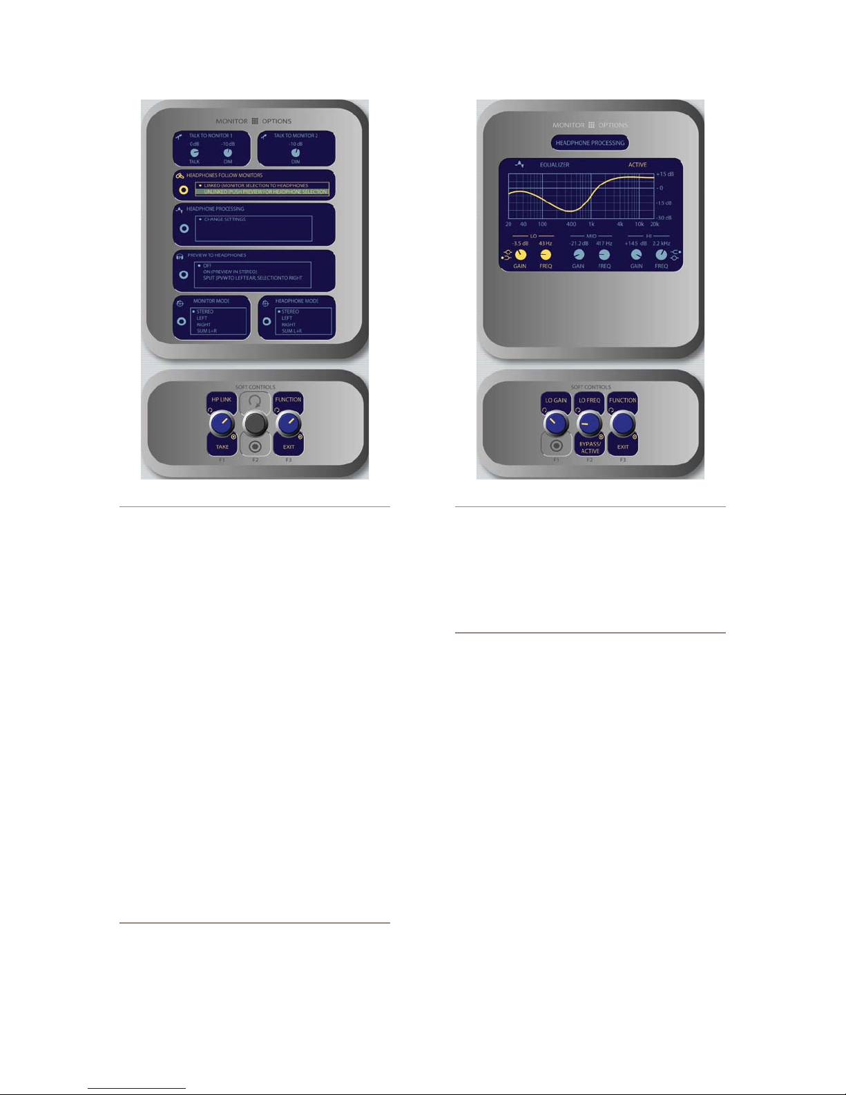
Figure 4-28: Monitor Options menu screen #1. Figure 4-29: Headphone EQ menu screen.
assigned to the monitor speakers. So how can
When the Talk to Monitor 1 Talk and Dim or
»
Talk to Monitor 2 Dim control is highlighted,
rotating the TALK LEV SoftKnob adjusts the lev-
els of the Monitor 1 Talk To and Dim levels and
the Monitor 2 Dim level.
When the Headphones Follow Monitors box
»
is highlighted, rotating the HP LINK/Take
chooses whether the headphone source will fol-
low the Monitor 1 source selection. Push the
knob to Take your selection.
Linked means that Headphone and Monitor
*
1 selections will mirror each other; making a
selecton from one bank of keys on the Moni-
tor Module will automatically choose the
same source on the other bank.
Unlinked allows Monitor 1 and Headphone
*
sources to be selected independently of each
other.
the operator select a headphone source if s/he
choosees to Unlink the headphones?
When Unlinked is chosen in the Headphones
Follow Monitors box, the Preview knob doubles
as the headphone source selector. When the
operator pushes the Preview knob, the Head-
phone Source menu is displayed. Voila!
When the Headphone Processing box is highlig-
»
ted, pressing the HP Proc/Take knob selects
Change Settings onscreen and takes the operator
to the H/P Process screen shown in Figure 4-29.
When the
EQ
screen is displayed, a graphical rep-
resentation of the equalization curve is displayed
as the controls are adjusted. The screen also in-
dicates the amount of cut/boost applied, and the
center frequency of each band.
Rotate the Function/Exit SoftKnob to high-
*
light the Lo, Mid or Hi band knobs shown
onscreen. Notice that the left and center Soft-
Knob labels change to display Lo Gain/Lo
The strongest link: You’ve noticed that there
are no Direct Selection Keys for the headphone
source on the Monitor + 2-Fader Module. By default, CR Headphones and Monitor 1 sources are
linked - the phones will play whatever source is
Freq, Mid Gain/Mid Freq and Hi Gain/Hi
Freq as you rotate the Function knob.
The leftmost SoftKnob is the
*
rotate to adjust the amount of
Gain
control;
gain or cut ap-
4: Element Operations • 67
©2008 Axia Audio — Rev. 3.0
Page 78

plied to the selected band.
Note that when you adjust Lo Gain, the
›
Shelf/Peak indicator next to the onscreen
control automatically shifts to Peak mode
when boost is applied, and shifts to Shelf
mode when cut is applied.
Note that when you select the Hi band, the
›
label below the Gain control displays Hi
Peak or Hi Shelf, depending on which
mode has been selected. Push the knob to
toggle between the two modes.
The center SoftKnob is the Freq control and
*
adjusts the center frequency of the selected
EQ band.
In Lo Freq mode, rotating the knob ad-
›
justs the center frequency of the low EQ
band (25 - 400 Hz).
In Mid Freq mode, rotating the knob ad-
›
justs the center frequency of the midrange
EQ band (100 Hz - 1 kHz).
In Hi Gain mode, the knob adjusts the
›
boost/cut of the high frequency band.
Pressing the center SoftKnob toggles EQ be-
tween Active and Bypass.
Note: High, Mid and Low band adjustments
provide up to 25 dB of cut and 15 dB of boost.
Element EQ features SmartQ™ automatic bandwidth system that varies the Q of the selected
parametric band to provide the most pleasing
EQ effect. For details on SmartQ, please refer
to Page 44 of this manual.
in the left headphone channel only. Program
audio is still present in the right channel of
the operator’s headphones.
After making a selection, push the knob to
*
Take the new value.
When the Monitor Mode box is highlighted, the
»
operator can rotate the Monitor/Take knob to
select from the following options.
Stereo: The selected source will be present-
*
ed in stereo on the Monitor speakers.
Left: The left channel of the selected source
*
will be presented in both Monitor speakers.
Right: The right channel of the selected
*
source will be presented in both Monitor
speakers.
Sum L+R: Both channels of the selected
*
source will be summed and presented to both
Monitor speakers.
After making a selection, push the knob to Take
»
the new value.
When the Headphone Mode box is highlighted,
»
the HP Mode knob is active. This control works
the same as the Monitor Mode control described
above, but affects the board operator’s headphone
channel.
Pushing the Function/Exit knob returns you to
»
the main Element screen.
When the Preview to Headphones box is
»
highlighted, the HP Prev/Take knob controls
whether audio from the Preview bus is fed to the
board op’s headphones, and if so, in what man-
ner. Rotating this knob selects from the following
options:
Off: The operator will not hear Preview au-
*
dio in the headphone channel.
On: audio from the Preview channel over-
*
rides the Headphone Monitor selection and
is sent to both the left and right channels of
the operator’s headphones.
Split: Audio from the Preview channel
*
4: Element Operations • 68
overrides the Headphone Monitor selection
The second Monitor Options screen (press the
Monitor Options key a second time) is shown in Fig-
ure 4-30:
Rotating the Function/Exit SoftKnob high-
»
lights the different control boxes onscreen, mak-
When the Rightmost Meter box is highlighted,
»
©2008 Axia Audio — Rev. 3.0
ing the highlighted control active. Labels on the
other SoftKnobs change depending on context.
rotating the Met Mode/Take knob selects how
the far right meter on Element’s main screen will
behave. Pressing this knob will Take your selec-
tion.
Dedicated means the meter will be slaved to
*
Page 79
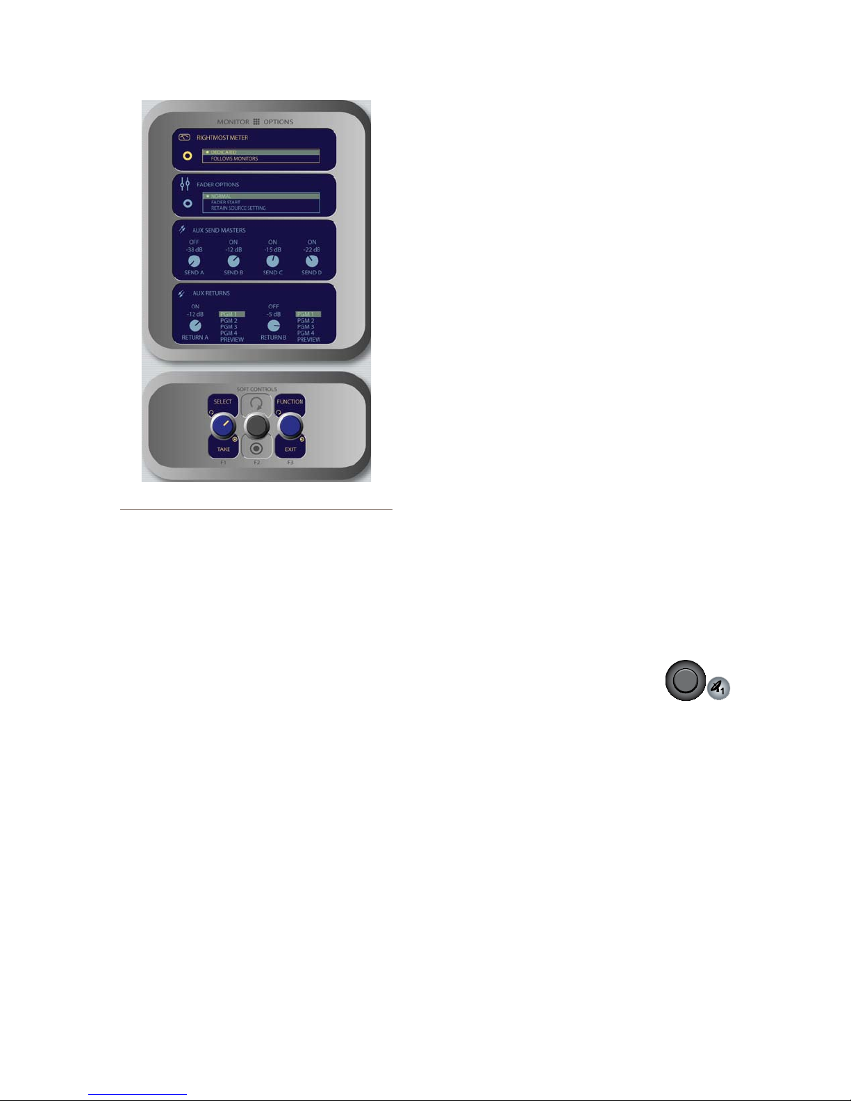
Figure 4-30: Monitor Options menu screen #2.
the PGM-4 bus.
Follow Monitors means the meter will show
*
levels for any source assigned to Monitor 1.
Send buses.
The Send A/B/C/D SoftKnobs, when ro-
*
tated, set the Master Send Gain for each Aux
Send bus. Pushing the knob toggles the se-
lected Aux Send Master On or Off.
Pushing the Preview knob sends the high-
*
lighted Aux Send mix to the Preview chan-
nel. Push to preview; release to end preview.
Element features two stereo Aux Return buses
»
whose output can be applied to any of the four
PGM buses. When the knobs in the Aux Returns
box are highlighted, the Return A/B knob af-
fects global gain settings for the master levels of
the two Aux Return buses.
The Return A/B SoftKnobs, when rotated,
*
set the Master Send Gain for each Aux Send
bus. Pushing the knob toggles the selected
Aux Return Master On or Off.
Rotate the adjacent Assign/Take knob to
*
choose which of the four Program buses (or
the Preview bus) to assign the output of the
selected Aux Return. Push the knob to Take
the assgnment.
When the Fader Options box is highlighted,
»
pressing the St. Mode SoftKnob selects between
fader-normal and European-style fader-start
channel activation methods.
Fader Normal: Selects the US method of re-
*
quiring talent to manually turn channels on
and off.
Fader Start: Selects the European conven-
*
tion of activating the channel and associated
machine logic when the fader is raised from
∞.
Retain Source Setting: Each individual
*
fader uses the settings specified in its Source
Profile.
Element features four stereo Aux Send buses for
»
use as utility, FX or IFB buses. When the knobs
in the Aux Send Masters box are highlighted,
the SEND A/B/C/D knob affects global gain
settings for the master levels of the four Aux
Pressing the Function/Exit SoftKnob at any
»
time returns you to Element’s main meter screen.
Monitor 1 Knob + Source Keys
•
This knob, at the bottom left of the Monitor section,
controls the selection and volume of the source heard
in the Monitor 1 speakers (typically the Control Room
monitors).
Rotate the knob to vary the gain of the Monitor
»
1 speakers.
Use the Direct Selection Keys in the column di-
»
rectly above the Monitor 1 knob to send the out-
put of Program 1 - Program 4 or the two Ex-
ternal monitor sources to the Monitor 1 speakers.
These keys light to denote the selected source.
You can listen to any frequently-used audio
»
stream in your facility instantly (such as a net-
work feed, off-the-air monitor or another studio’s
Program output) by assigning it to one of the two
4: Element Operations • 69
©2008 Axia Audio — Rev. 3.0
Page 80
4: Element Operations • 70
External selector keys - like preset buttons on a
car radio.
Press and hold both External selector keys to
»
open the Monitor 1 Source menu, which al-
lows you to select from a list of Program and Aux
Send buses.
Programming the External Monitor Selector keys: If you press and hold either of these
keys for ve seconds, a list of available audio
streams will pop up onscreen. You can then
scroll through this list and select the source you
want to hear in the monitors when that key is
pressed. Each External key is independently
programmable.
You can also pre-program the source assigned
to these keys when you construct or capture
Show Proles, using the options available on the
Monitor page of the Show Prole setup menu.
Headphone Knob
•
This knob, at the bottom right of the Monitor section,
controls the volume of the source heard in the board
operator’s headphones.
Rotate to vary the gain of the Headphone feed.
»
By default, the Headphone feed is linked to
»
and follows the Monitor 1 source selection. To
unlink the two and choose an independent head-
phone source, please see the description on Page
66 of this manual.
Preview To HP Key
•
This key toggles the Preview To Headphone func-
tion. When active, this function sends Preview audio
to the board operator’s headphones. When inactive, au-
dio from the Preview bus is heard exclusively in the
Preview speakers. The Preview To HP key illuminates
when this function is active.
There are three different Preview to HP modes; the
current mode is indicated by an annunciator on the Ele-
ment display screen just below the headphone selection
tally.
Off: When Preview to HP is off, the selector key
»
is unlit. No preview audio will be heard in the
board-op’s HP path.
On: Pressing the Preview to HP key once from
»
the Off state sends preview audio, when present,
into both sides of the operator’s headphone feed,
overriding the Monitor audio. The Preview to
HP key is now lit.
Auto: Pressing the Preview to HP key a sec-
»
ond time toggles Auto mode. In this mode, audio
from the Preview channel overrides the Head-
phone Monitor selection in the left headphone
channel only. Program audio is still present in
the right channel of the operator’s headphones.
Preview Knob
•
This knob, at the top right of the Monitor section,
controls the volume of the source heard in the Preview
(cue) speakers. Rotate the knob to vary the gain of the
Preview speakers.
The Preview knob is also used to select the source
of the CR Headphone feeed when headphones are not
linked to the CR Monitor selection. Please see Page 66
of this manual for more information on this function.
Monitor 2 Knob
•
This knob, at the top left of the Monitor section, con-
trols the selection and volume of the source heard in the
Monitor 2 speakers (typically Studio or News booth
monitors).
Rotate to vary the Monitor 2 speaker gain.
»
Push the knob to see an on-screen display of
»
sources that can be assigned to the Monitor 2
feed. Rotate to highlight the desired source, and
push again to “take”.
Talk To Monitor 2 Key
•
The board operator can push and hold this key to
talk to the talent listening to the Monitor 2 feed. While
the key is depressed, audio from the Control Room mic
channel is fed, pre-fader, to the Monitor 2 speakers
and headphones (if used). Releasing the key ends the
talkback function.
Other Controls
Keys in this section are used to load Show Profiles,
©2008 Axia Audio — Rev. 3.0
Page 81
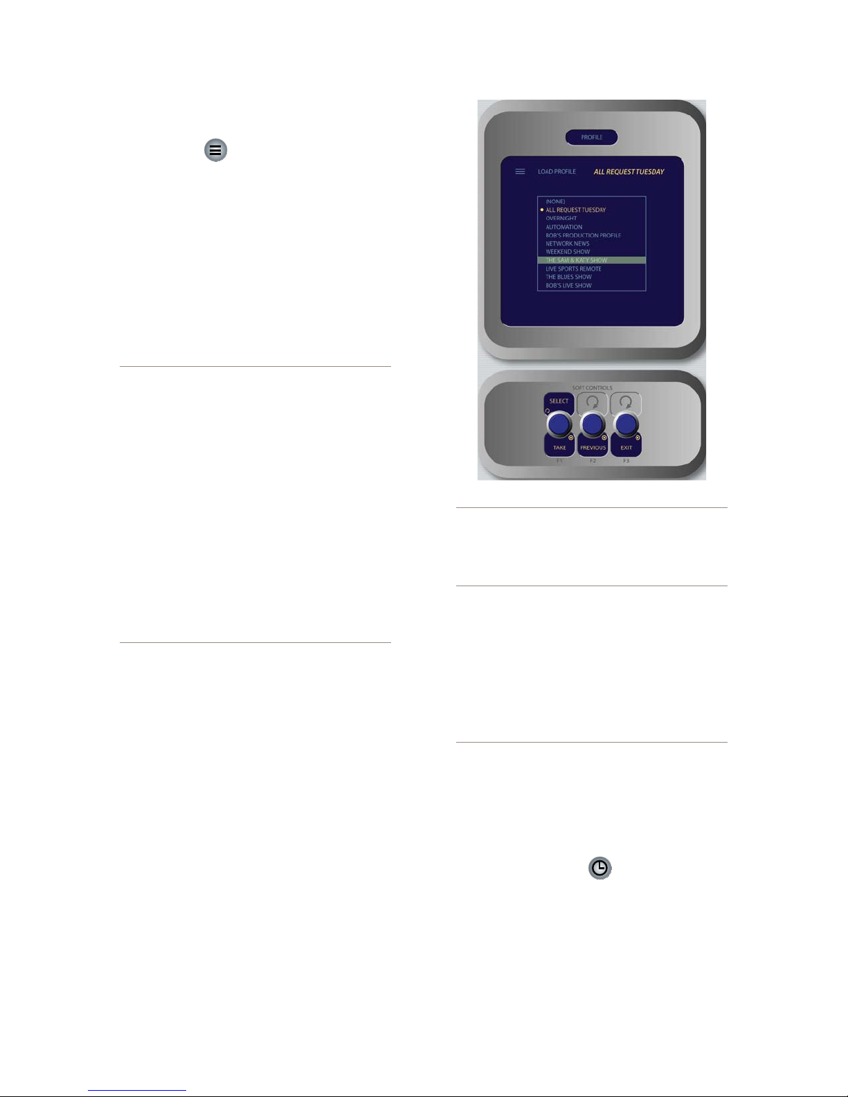
control the onboard clock and timers, engage Record
Mode and invoke hidden setup screens.
Prole Key
•
Pressing this key allows the board operator to browse
and select from a list of saved Show Profiles, custom
surface configurations that can be loaded as needed to
reconfigure Element for different shows and talent.
As soon as you “take” a new show profile, Element
begins loading it. During the profile loading process, a
status line reads Loading (Show Profile Name) to
inform the operator of the operation in progress.
LOADING A NEW SOURCE WHILE ANOTHER
SOURCE IS STILL ACTIVE: Element will nev-
er interrupt an active source in order to load a
new one.
Let’s say that the operator has a satellite
feed assigned to Channel 10, and this source
is currently on-the-air (assigned to Program-
1, fader up, channel On). The board op loads
a new Show Prole to ready Element for
the next show; the Show Prole he’s loading has a CD player assigned to Channel
10. Obviously, there’s a conict.
Instead of blindly changing the channel source
and interrupting audio that’s on-the-air, Element
queues the new source. When the board op is
nished with the satellite feed, he turns the
channel Off and the CD player automatically
loads.
Along with selecting a new Show Prole to load,
users can reload the currently active profile, resetting
the board to a “nominal” state if they wish to return
to their normal configuration after making on-the-fly
changes.
Select / Take: Rotate this knob to scroll through
»
the on-screen list of available Show Profiles. Push
the knob to “take” the new Show Profile.
Previous: When you load a new Show Profile,
»
Element remembers the previously loaded Pro-
file until you exit the Show Profile screen. The
Previous command functions as a “speed key,”
highlighting the previously assigned source in
the source list and allowing the operator to re-
turn to it should they change their mind. Press
to “take.”
Figure 4-31: Load Prole screen.
Exit returns the operator to Element’s main op-
»
erating screen.
DON’T PANIC! Element is full of options intended to make life on-air easier and more intuitive
for today’s talent. However, it’s possible for talent not yet familiar with the way Element works
to “get lost” in the option settings.
Pressing and holding the Prole key for ve
seconds instantly clears changes made to the
current Show Prole, resetting the Show Prole’s default settings. All is well, and your jock
once again knows where his towel is.
Timer Section
The Timer control keys operate Element’s onscreen
event and countdown timers, and allow users to set op-
tions determining the behavior of these timers.
Timer Options Key
•
Pressing the Timer Options key allows users to ad-
just how the onscreen timers behave. Pressing the Timer
Options key once opens the Count Up Timer controls;
pressing it twice opens the Countdown Timer.
4: Element Operations • 71
©2008 Axia Audio — Rev. 3.0
Page 82
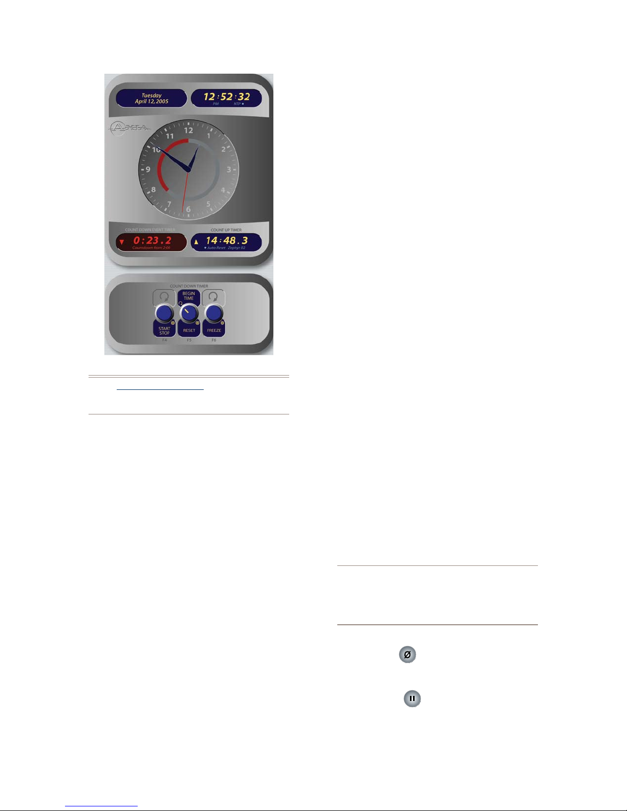
4: Element Operations • 72
Figure 4-32: Timer controls.
Note: Pressing and holding the Timer Options
Key opens the Clock & Timer Options Menu
discussed in Chapter 1.
The Count Up Timer is an event timer with three
modes, which can be set to start/stop/reset either au-
tomatically or manually. Using Source Profiles, you
can determine whether individual sources will start or
stop this timer automatically; the onscreen controls de-
scribed below allow the operator to override or modify
those settings.
Rotate the Timer Mode/Reset SoftKnob to
»
choose how the event timer will operate. Your
choice will be displayed onscreen just below the
Count Up Timer readout.
Choose Manual to start, stop and reset the
*
timer by hand using the controls displayed
when the Timer Options key is pressed.
Choose Auto-Reset and the timer will au-
*
tomatically reset to zero and begin counting
whenever a fader whose source starts the
timer is turned On.
Choose Auto-Add to have the timer count
*
up when a designated source’s fader is turned
On and stop counting when that source is
turned Off. In this mode, the timer will not
reset to zero when it is started.
Press Timer Mode/Reset to return the Count
»
Up Timer to zero.
Press Start/Stop to begin and end the Timer’s
»
countdown.
Pressing Freeze holds the on-screen Timer dis-
»
play so you may take note of it; the timer con-
tinues to count while the display is frozen, and
a second press of the Freeze again displays the
running elapsed time counter.
The Countdown timer is useful for counting down to
network joins, top-of-hour IDs, and other events which
require exact timing. The Countdown timer is started,
stopped and reset manually using the controls displayed
when the Timer Options key is pressed. To use:
Rotate the SoftKnob marked Begin Time/Re-
»
set to set the interval from which the countdown
will begin. As you rotate, small numbers below
the red counter onscreen will inform you of the
new countdown interval.
Press the Begin Time/Reset knob to set the
»
new time you’ve dialed in.
Press the Start/Stop knob to begin or end the
»
countdown.
Pressing Freeze holds the on-screen Timer dis-
»
play so you may take note of it; the timer con-
tinues to count while the display is frozen, and
a second press of the Freeze again displays the
running elapsed time counter.
“Look at me!!” During the last 60 seconds of the
countdown, the inner ring of Element’s onscreen
analog clock will turn red and diminish as time
passes, providing the operator with a visual cue
to how much time is left until zero.
Reset Key:
•
Pressing this key resets Element’s Count Up Timer.
Freeze Key:
•
Pressing Freeze holds the Count Up Timer dis-
»
play so you may take note of it; the timer con-
©2008 Axia Audio — Rev. 3.0
Page 83
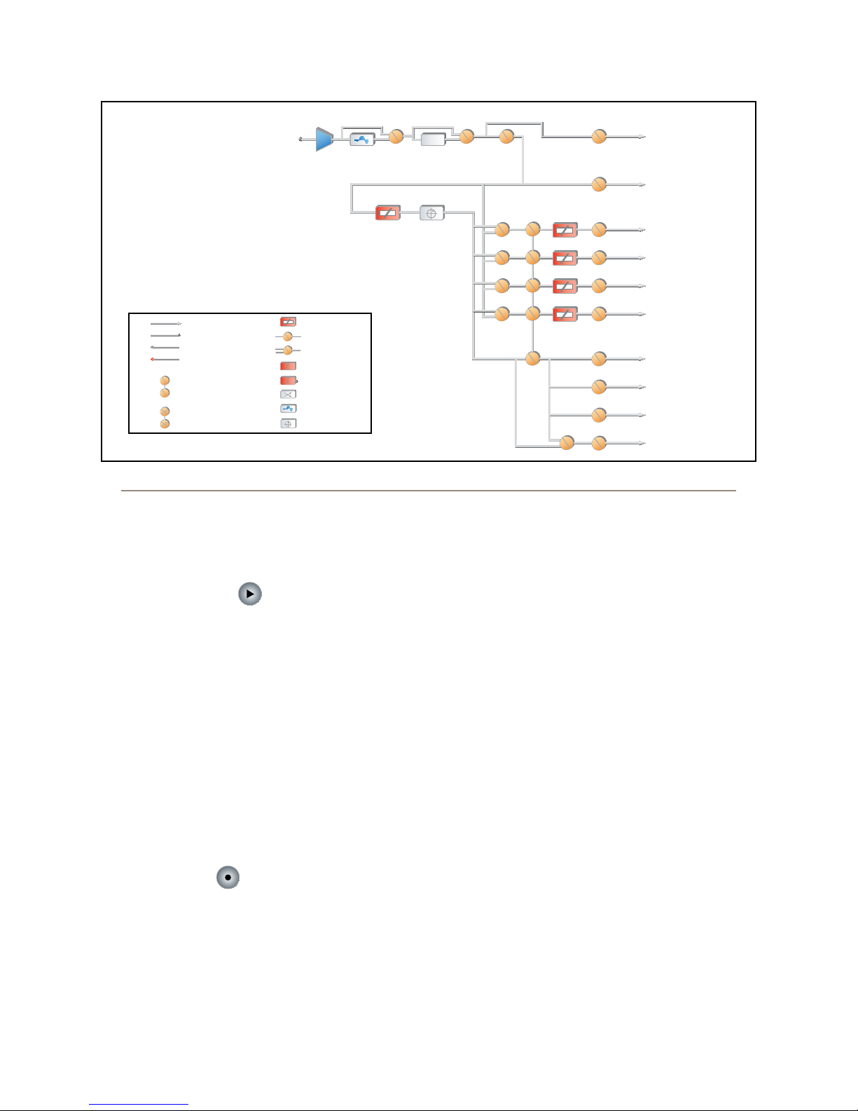
PRE ON
Σ PROGRAM 1
PGM 1
Σ PROGRAM 2
Σ PROGRAM 3
Σ PROGRAM 4
PGM 4
PGM 3
PGM 2
HOST
MICROPHONE
SOURCE
EQ / DYN
PHASE
Ø
PRE FDR
PRE FDR
PRE FDR
PRE FDR ON
AUX 1
Σ AUX SEND 1
AUX 1
AUX 2
Σ AUX SEND 2
AUX 2
AUX 3
Σ AUX SEND 3
AUX 3
AUX 4
Σ AUX SEND 4
AUX 4
PVW
Σ PREVIEW
FADER PAN
TALK TO X MIX
Σ TALK TO X
MUTE
HI, MID, LO EQ
COMPRESSOR
DE-ESSER
NOISE GATE
NORMAL
INVERT
TO INTERNAL NODE
GAIN CELL
SPST SWITCH
PHYSICAL CONNECTION
EXTERNAL CONNECTION
FROM INTERNAL NODE
SPDT SWITCH
ADD
SIGNAL MODE
DSP CELL
PAN / BALANCE
SUBTRACT
GANGED SWITCHES
MUTUALLY EXCLUSIVE SWITCHES
Legend
Figure 4-33: Control Room Operator Microphone channel block
tinues to count while the display is frozen, and
a second press of the Freeze again displays the
running elapsed time counter.
Start/Stop Key:
•
If the Count Up Timer is not running, pressing this
starts it. If the timer is running, pressing this key stops
the countdown and retains the last displayed timer in-
terval.
Record Mode Section
Element’s Record Mode is a special “one-touch”
mode which can be set to automatically start a desig-
nated record device so that talent can record a phone call
or remote interview with a single button-press. Record
Mode can be enabled or disabled for each Show Prole
(see Chapter 5, “Show Profiles”, for details).
Engage Key:
•
Press this key to put Element into Record Mode.
Pressing this button activates a pre-determined record-
ing device. Pressing the key a second time deactivates
Record Mode and stops the recorder.
“Magic Key” Sequences for Monitor + 2-Fader Module
The list of “Magic Key” sequences for the Standard
Monitor Module are:
IP Address Book: Press and hold the * (star), 4 &
•
7 keys on the keypad for 5 seconds.
Clock & Timer Settings: Press and hold the Timer
•
Options key for 5 seconds.
Capture Mode: Press and hold the * (star) & 2
•
keys on the keypad for 5 seconds.
Help Screen: Press and hold the * (star) &
•
# (pound) keys on the keypad for 5 seconds.
Test Mode: Press and hold the Help and Right Ar-
•
row keys for 5 seconds.
Source-Specic Channel Controls
Some fader functions change their behavior to suit
the type of source assigned to the fader. A Guest Mic in-
put has unique functions different from those of a Codec
input, and so forth. In this section we’ll explain the chan-
nel functions unique to each type of source input, as well
as providing functional block diagrams of each type.
©2008 Axia Audio — Rev. 3.0
4: Element Operations • 73
Page 84

Control Room Operator Mic Channel Operation
The Control Room Operator microphone is the
board operator’s mic. It’s always located in the Control
Room, so activating a channel designated as the CR Op-
erator mic affects Studio 1 monitor speaker and Preview
speaker muting.
ers will mute when this channel is turned on, or when
Preview or Record Mode are selected. Control Room
Guest mics can be turned on and off remotely, and pro-
vide on/off status to a remote logic device. Remote Talk
and Remote Mute functions are also provided, and can
be activated using a remote On/Off/Talk/Mute panel.
When the board operator pushes a Talkback key, all
output bus assignments for the Control Room Operator
microphone are temporarily muted, while his mic’s au-
dio is routed to the requested Talkback destination. Re-
leasing the button returns the channel outputs to normal.
(Pushing your own Talkback key does nothing.)
Pressing the channel On key for the CR Operator
Mic while the channel is already on will mute the chan-
nel until the button is released, acting as a “cough” func-
tion for the board operator. On-air status and speaker
mutes are unaffected by this action. The CR Operator
microphone channel will mute both the Studio 1 speak-
ers and the Preview speakers whenever the channel is
On, or if Preview or Record Mode Engage keys are
selected.
The block diagram for this channel selection is
shown in Figure 4-33.
Producer Microphone Channel Operation
The Producer’s microphone is meant to be used at
position within the Control Room where a morning
show or talk show producer would normally sit. This
mic type mimics the operation of the Control Room mic
described above, but does not include the “cough” func-
tion; also, a Producer mic can use Talkback to talk to
the board op, but cannot talk directly to the Monitor 2
talkback channel.
Control Room Guest Microphone Channel Operation
There are often microphones in the Control Room
other than the board operator’s; i.e., an in-studio guest
wing, or perhaps an announcer located physically near
the board op. These microphones control the muting of
the Control Room monitor speakers.
Remote Talk lets talent and guests communicate
with the board operator. When Talk is remotely activat-
ed on a CR Guest mic channel, outputs to program buses
for that channel are muted and the mic audio is fed to the
Talkback bus. While this is active, the Status Symbol on
the guest’s fader strip displays a T icon. When the user
stops talking, the channel returns to normal. The opera-
tor can then reply using the fader’s Talkback key.
When the Remote Mute function is activated, the
Status Symbol displays X, and all the channel outputs
are muted until the command is released.
Control Room Guest Microphone channels will mute
the Control Room speakers and the Preview speakers
whenever the channel is On, or if Preview or Record
keys are selected. If only the Phone key is selected, the
Control Room speakers will mute independently, leav-
ing the Preview speakers un-muted.
Finally, Control Room Guest Microphone channels
have provisions for an individual Headphone feed. This
is especially useful for talent and guests in the same
room as the board operator; their headphone feeds will
all monitor the audio selected on the Monitor 2 selec-
tor, but the board op can communicate with each person
privately using Talkback key on their fader strip.
The block diagram for this channel selection is
shown in Figure 4-34.
Studio Microphone Channel Operation
The third type of mic channel is a Studio Microphone.
This mic is typically located in a location separate from
the control room — perhaps a voice-over booth, a talk
studio separated by glass, or a news booth.
4: Element Operations • 74
The Studio 1monitor speakers and Preview speak-
Logic for Studio Microphone channels is identical
©2008 Axia Audio — Rev. 3.0
Page 85
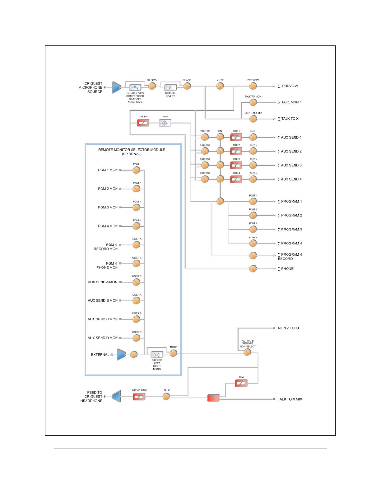
DRAWING UPDATED
2-11-08
Figure 4-34: Control Room Guest Microphone channel block
4: Element Operations • 75
©2008 Axia Audio — Rev. 3.0
Page 86
STUDIO GUEST
MICROPHONE
SOURCE
EQ / DYN
PHASE
Ø
PRE FDR
PRE FDR
PRE FDR
PRE FDR ON
AUX 1
Σ AUX SEND 1
AUX 1
AUX 2
Σ AUX SEND 2
AUX 2
AUX 3
Σ AUX SEND 3
AUX 3
AUX 4
Σ AUX SEND 4
AUX 4
PRE ON
Σ PROGRAM 1
PGM 1
Σ PROGRAM 2
Σ PROGRAM 3
Σ PROGRAM 4
PGM 4
MUTE PREVIEW
Σ PREVIEW
FADER PAN
PGM 3
PGM 2
JOIN TALK MIX
Σ TALK TO X
TALK TO MON1
Σ TALK MON 1
HI, MID, LO EQ
COMPRESSOR
DE-ESSER
NOISE GATE
NORMAL
INVERT
MON 2 FEED
PGM 1 MON
PGM 1
PGM 2 MON
PGM 2
PGM 3 MON
PGM 3
PGM 4 MON
PGM 4
USER A
USER A
USER B
USER B
USER C
USER C
USER D
USER D
MODE
STEREO
LEFT
RIGHT
MONO
REMOTE MONITOR SELECTOR MODULE
(OPTIONAL)
ACTIVATE
REMOTE
MON SELECT
FEED TO
STUDIO GUEST
HEADPHONE
TALK
DIM
TALK TO X MIX
4: Element Operations • 76
Figure 4-35: Studio Microphone channel block
©2008 Axia Audio — Rev. 3.0
Page 87
to that of the Control Room Guest Microphone chan-
LINE
SOURCE
EQ / DYN
PHASE
Ø
MODE
PRE FDR
PRE FDR
PRE FDR
PRE FDR ON
AUX 1
Σ AUX SEND 1
AUX 1
AUX 2
Σ AUX SEND 2
AUX 2
AUX 3
Σ AUX SEND 3
AUX 3
AUX 4
Σ AUX SEND 4
AUX 4
PRE ON
Σ PROGRAM 1
PGM 1
Σ PROGRAM 2
Σ PROGRAM 3
Σ PROGRAM 4
PGM 4
FADER PAN
PGM 3
PGM 2
JOIN TALK TO X MIX
Σ TALK TO X
MUTE PREVIEW
Σ PREVIEW
HI, MID, LO EQ NORMAL
INVERT LEFT
INVERT RIGHT
INVERT BOTH
STEREO
LEFT
RIGHT
SUM L+R
nel. Studio Microphone channels can be turned on and
off remotely and provide on/off status to a remote logic
device. Remote Talk and Remote Mute functions are
providedfor use with a remote On/Off/Talk/Mute panel.
Remote Talk lets talent and guests communicate
with the board op. When Talk is remotely activated, out-
puts to program buses for that channel are muted and the
source audio is fed to the Talkback bus. While active,
the Talkback key is lit and the Status Symbol displays
TALK. When the user stops talking, the channel returns
to its previous state, and its Talkback key flashes for
three seconds, alerting the board op to the guest who
spoke to him, and enabling reply via the Talkback key.
When Remote Mute is activated, the Status Symbol
will display MUTE, all channel outputs are muted until
the key is released, and the channel is again active.
The Monitor-2 speakers mute when a Studio Micro-
phone channel is turned on, or if it is assigned to the
Program-4/Record bus.
The Studio Microphone channel can be associated
with an individual Headphone feed. All Studio Micro-
phone-associated feeds will monitor the audio selected
on the Monitor 2 selector, but the board op can commu-
nicate privately using the Talkback function.
The block diagram for this channel selection is
shown in Figure 4-35.
Line Channel Operation
Line-level devices like CD players, tape players, etc.,
use the Line Channel profile. The Line Channel is ste-
reo, but the user can change the input mode to mono, left
only or right only by using the Pan & Mode key in the
Master Module’s Channel Options section.
Line channels have a variety of remote logic func-
tions available at the GPIO interface. On and Off keys
can be remotely controlled, as well as the Preview key.
Each function has a corresponding lamp driver.
Figure 4-36: Line channel block
©2008 Axia Audio — Rev. 3.0
4: Element Operations • 77
Page 88
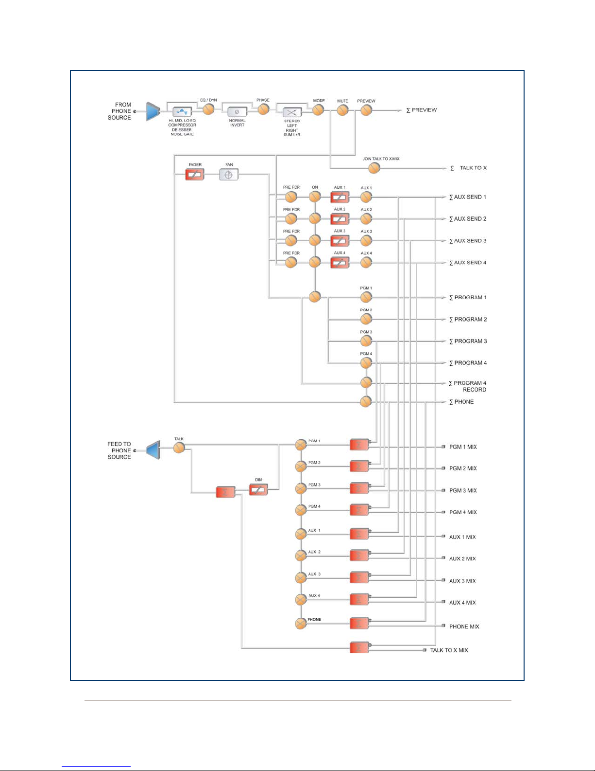
DRAWING UPDATED
2-11-08
4: Element Operations • 78
Figure 4-37: Phone channel block
©2008 Axia Audio — Rev. 3.0
Page 89

A Reset function is provided to remotely turn the
channel Off while suppressing the Stop command, use-
ful for allowing certain types of tape machines to re-cue.
You’ll also find a Ready command which will remotely
illuminate the Off lamp on the Element channel and ac-
tivate the GPIO Off lamp driver, allowing source equip-
ment to signal the operator with either a steady-state Off
button (indicating source ready) or a flashing Off button
(indicating source next). Refer to the GPIO Node User’s
Manual for information on interfacing to the GPIO’s in-
puts and outputs.
The block diagram for this channel selection is
shown in Figure 4-36.
Phone Channel Operation
The Phone Channel profile is used, naturally, for tele-
phone hybrid audio sources. Each Phone Channel has its
own discrete Feed-to-Source mix-minus output.
on and off remotely, and will provide on/off status to a
remote logic device. Remote Preview is also provided,
as are lamp drivers for On, Off and Preview. Start and
Stop pulses can be sent when the channel is turned on or
off, respectively. See the GPIO User’s Manual for infor-
mation interfacing to GPIO inputs and outpus.
The block diagram for this channel selection is
shown in Figure 4-37.
Codec Channel Operation
The Codec Channel is used for codec sources. Like
the Phone Channel, each codec source is brought up on
its own channel, and an individual Feed-to-Source (mix
minus) output is provided for each codec. Codec Chan-
nels can be turned on and off remotely and provide on/
off status to a remote logic device. Remote Talk and
Remote Mute are also provided, allowing talent to take
control using their own On/Off/Mute/Talk panels.
Each Element can accomodate as many unique, au-
tomatically-generated mix-minus feeds as it has faders.
If the Feed-to-Source mode is set to “Auto” (the most
common option - see Chapter Two, “Configuring In-
puts,” for the section entitled “Source Profile Options”),
phone callers hear the output of the Program-1 bus, mi-
nus himself, when the the channels they’re assigned to
are On. When the caller’s channel is Off, their channel’s
Talkback key is lit and they hear the Board Operator’s
mic routed to their Talkback feed.
When a Phone Channel has been assigned to an
Element fader, the Status Symbol display located above
the channel name will display an icon to show the board
operator what is being fed to the caller.
Phone feed-to-source outputs can also be locked to
backfeed only PGM-1, PGM-2, PGM-3 or PGM-4, us-
ing the options provided when constructing the Source
Profile for your hybrid. This automatic switching mode
makes it very easy to prep callers and then seamlessly
put them on the air with a minimum of button pushes.
(See Chapter Two).
Channels configured for Phone sources can be turned
Talk enables remote talent to communicate with the
board op using the Talkback bus. When Talk is acti-
vated, all outputs for that channel are muted and the
source audio is fed to the Talkback bus; the channel’s
Talkback key lights, and its Status Symbol displays
T. When the user stops talking, the channel returns to
normal, and its Talkback key flashes for three seconds,
alerting the board operator to the guest who spoke to
him, and enabling him to reply using the Talkback key.
When the remote mute function is activated, the Sta-
tus Symbol displays M, and all the channel outputs are
muted until the command is released.
The mix-minus output normally feeds Program-1
audio to the remote, but can be switched to Program-
2. The Feed-to-Source output on a Codec Channel is
a dual mono output, occupying both sides of the stereo
pair. The Left output is normally used for remote talent’s
headphone feed, and is interrupted by Talkback audio
when the board op talks to the remote. The Right output
sends uninterrupted program audio for use as a PA feed.
The block diagram for this channel selection is
shown in Figure 4-38.
4: Element Operations • 79
©2008 Axia Audio — Rev. 3.0
Page 90
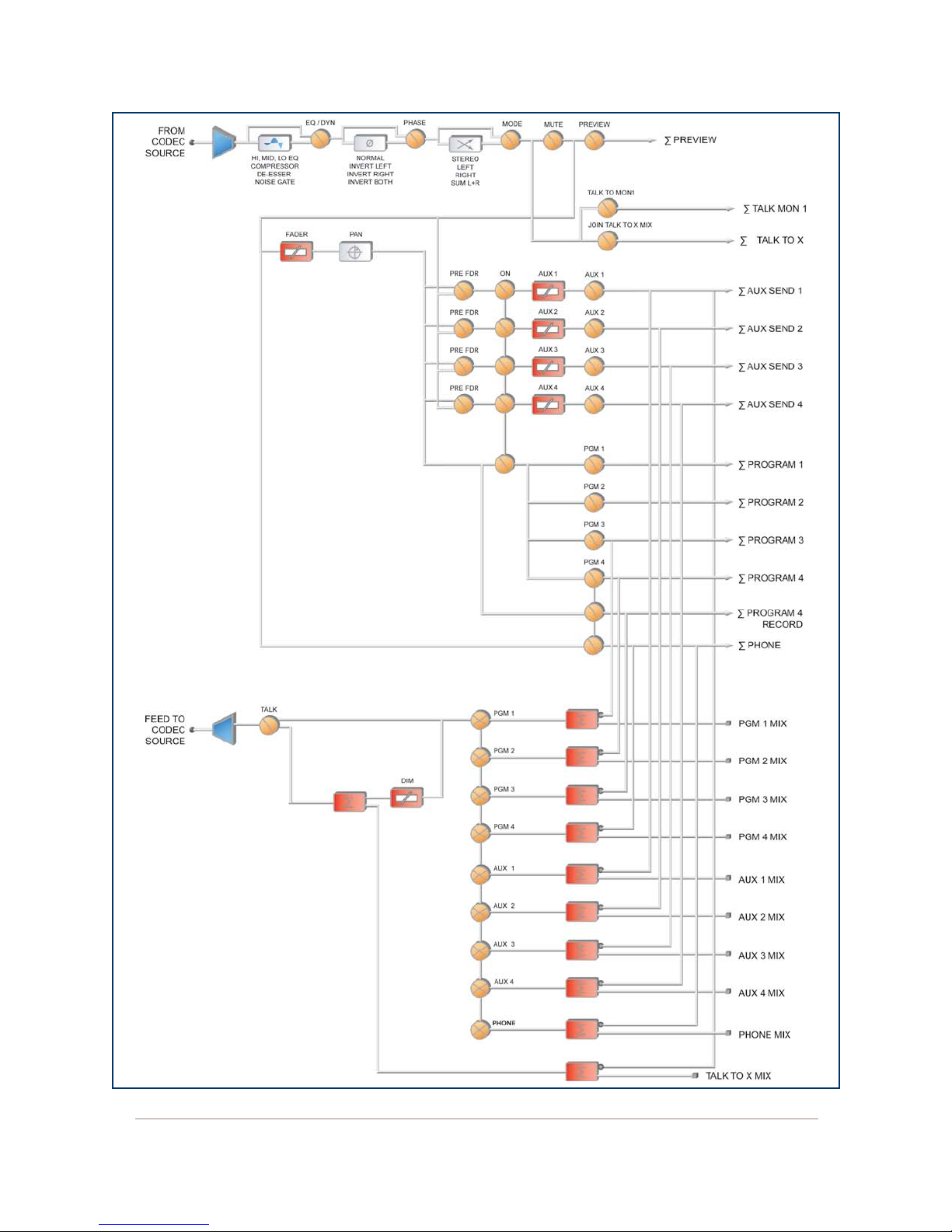
DRAWING UPDATED
2-11-08
4: Element Operations • 80
Figure 4-38: Codec channel block
©2008 Axia Audio — Rev. 3.0
Page 91
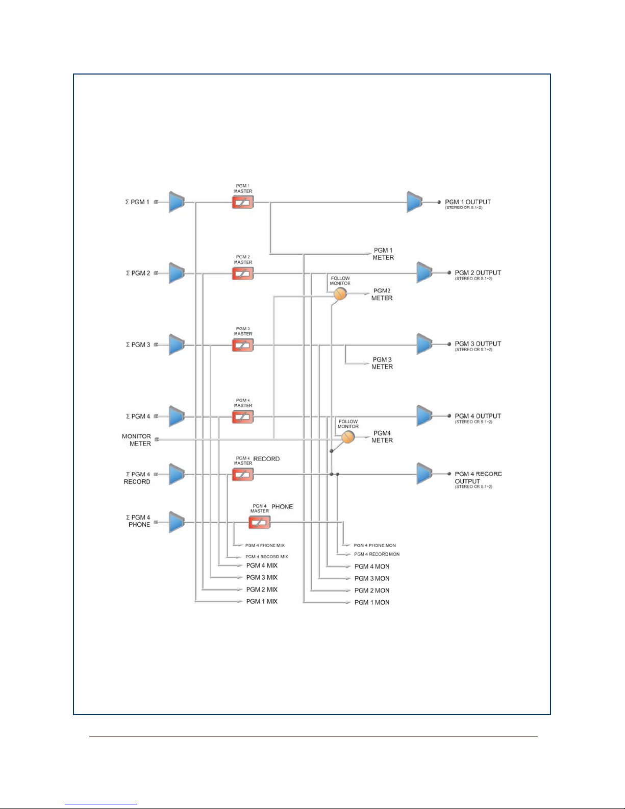
DRAWING UPDATED
2-11-08
Figure 4-39: Element Master Output block
©2008 Axia Audio — Rev. 3.0
4: Element Operations • 81
Page 92
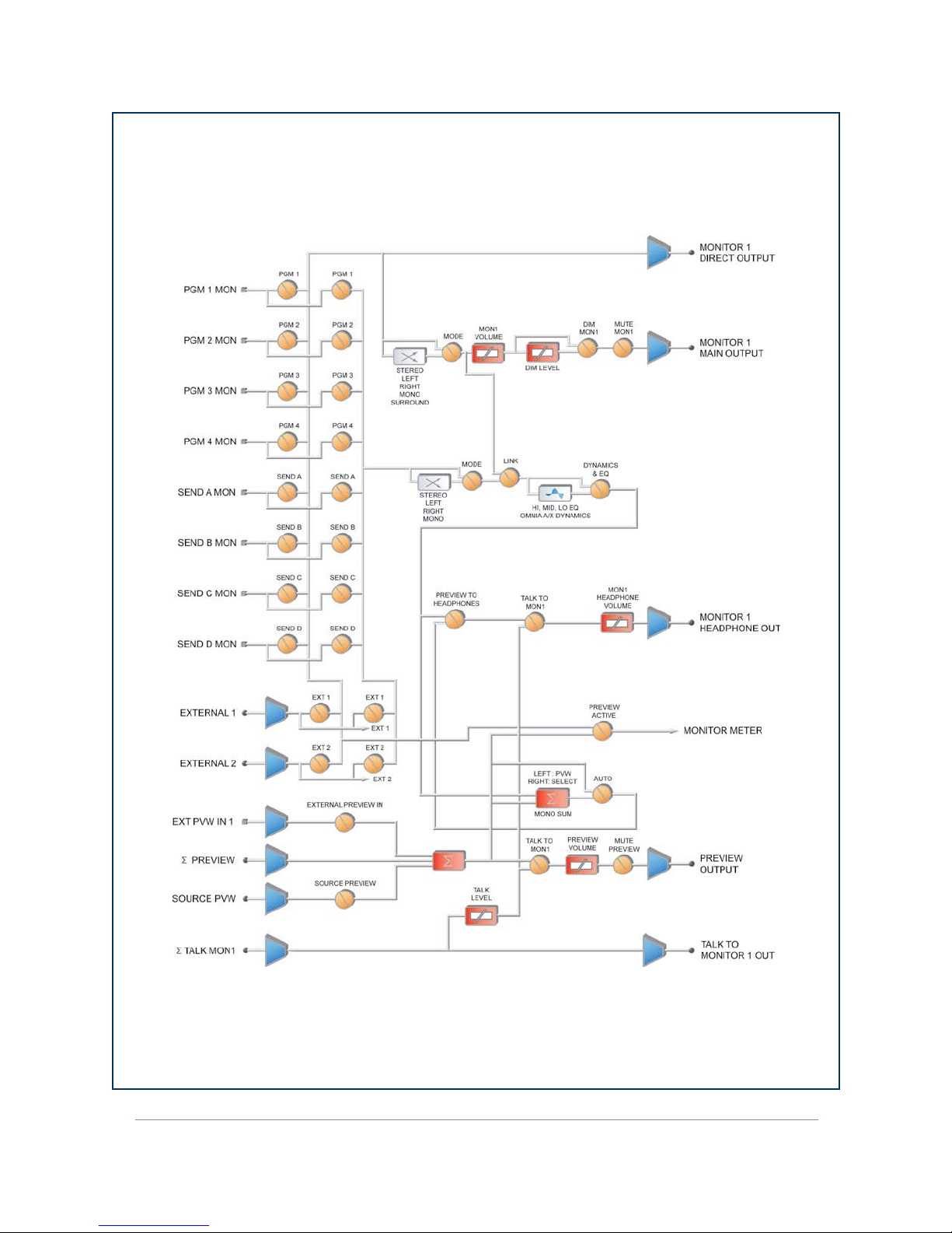
DRAWING UPDATED
2-11-08
4: Element Operations • 82
Figure 4-40: Monitor 1 Output block
©2008 Axia Audio — Rev. 3.0
Page 93
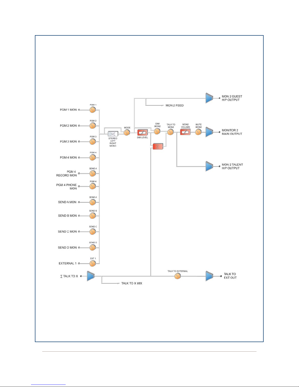
DRAWING UPDATED
2-11-08
Figure 4-41: Monitor 2 Output block
4: Element Operations • 83
©2008 Axia Audio — Rev. 3.0
Page 94

What’s Next
One of Element’s most powerful features is the abil-
ity to instantly reconfigure the entire surface for differ-
ent show types. Join us in Chapter Five to learn how to
set up and use Show Profiles. q
4: Element Operations • 84
©2008 Axia Audio — Rev. 3.0
Page 95

in “ready mode.”
Chapter Five:
Show Profiles
If you’ve already read Chapter Two, “Configuring
Inputs,” you already have a good understanding of how
Source Profiles are essential to Element operation.
In the same way that Source Profiles allow you to
pre-determine how an individual channel is configured
when a source is loaded, Show Profiles let you build con-
figuration files that can be loaded to determine how the
entire Element behaves, and which sources are loaded,
and what channels they appear on.
By assembling sets of Show Profiles, each user can
have the board set up his or her favorite way — sources
placed where they’re most useful, monitors set to the ap-
propriate feed, headphones conforming to personal pref-
erence. Or, you can use Show Profiles to define different
types of broadcasts – one for the morning show, one for
talk segments, one for musical guest interviews, one for
unattended operation – that need only to be loaded to
instantly reconfigure the board for use with a different
situation.
Creating A Show Profile
The first step in building a Show Profile is to set up
Element using the Channel Options, Monitor Options
and and other board options as described in Chapter
Four, “Element Operations.” Get started by assigning a
source to each Element channel using the Options keys
at the top of each channel.
Reminder: You can speed the setup process
by “Channel Jumping” while using the Options
menus.
For example, to quickly assign sources, select
the Options key on Channel 1 and choose
Source from the Channel Options menu. Use
the Soft Knobs, Control Knob or Nav Keys to
select a source from the list; “take” the source
and then press the Options key on Channel 2. You’ll see the indicator at the top of the
Channel Options screen change to read Chan-
nel 02 to conrm that you’re now program-
ming Channel 2.
Repeat the proceedure until you’ve programmed
all your channels. You can now choose other
Channel Options to congure using the same
method.
After you’ve assigned a source for each channel, you
can configure the rest of the Channel Options:
Equalization,
•
Pan / Balance,
•
Aux Sends, and
•
Feed to Source.
•
Build A Show
Element’s Web interface, which you’ve used to con-
struct Source Profiles, is also used to help build Show
Profiles, so make sure a computer with a Web browser is
connected to your Livewire network within easy reach.
Your Element is shipped from the factory with a de-
fault Show Profile. This loads the first time you turn on
your Element; it provides the “blank slate” you’ll use to
construct custom Show Profiles. You’ve no doubt been
exploring your Element, so you might want to reload
the Default Show Profile using Show Proles key lo-
cated on Element’s Master Module to make sure you’re
When you’ve configured all Channel Options, con-
tinue on and make monitor and headphone selections
and adjust Aux Send / Aux Return settings if necessary,
since these are all saved in Show Profiles as well.
When you’ve got the board configured to your satis-
faction, proceed to the next section.
Capture It!
It’s now time to save your Element configuration.
Enter Element’s IP address in your Web browser.
When the Main Menu appears, choose “Configuration”
©2008 Axia Audio — Rev. 3.0
5: Show Proles • 85
Page 96
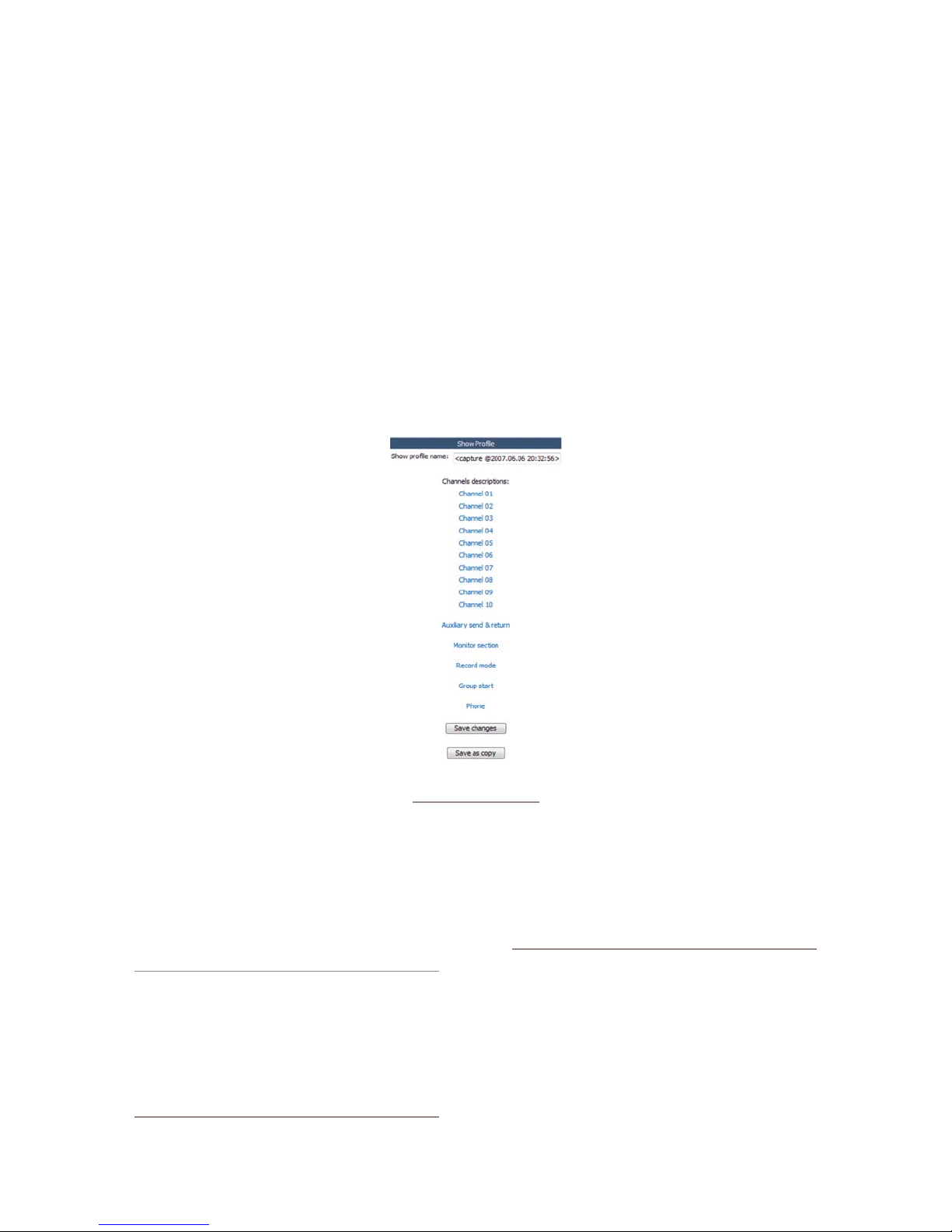
5: Show Proles • 86
under the “Sources & Profiles” heading on the sidebar
menu. This is where you’ll come whenever you need to
capture, construct or administer a Show Profile.
Under ths Show Profiles list, you’ll then find four op-
tions:
Default Show Prole. This is the “starter” pro-
»
file that comes with Element. If you wish, you
can overwrite this with your preferred default
options; otherwise, consider it as “return to zero”
configuration option, for use in returning Ele-
ment to a “blank slate” condition.
New Show Prole. Choose this option when
»
you want to construct an entire
Show Profile completely from
scratch.
Capture Show Prole. Takes
»
a “snapshot” of the current board
state and saves it for recall. This is
the option we’ll use in just a mo-
ment.
You’ve already set up your Element, so
now you can just “capture” your settings
for further use. Choose Capture Show
Prole from the menu. You’ll be prompt-
ed to give your new profile a unique name;
after you do, it’ll be added to the list of
available profiles. Voila! You’ve just cre-
ated and saved a Show Profile, which can
Figure 5-1: Show Prole
Settings Menu
now be recalled for use whenever you
wish.
However, there may be a few more options you’d like
to tweak — options not accessible from Element itself.
Let’s go a little deeper into Show Profiles to find out
exactly what’s available to you.
Suggestion: As part of Element training, show
your talent how to use the Channel Options and
Monitor Options menus (discussed in Chapter
Four) to assign sources and set monitor options.
Then, let them set up the board exactly the way
they want it, then use the Capture command to
save their work. This way, talent gets the satisfaction of personalizing their own Element con-
guration — and saves you the work!
Show Profile Options
Although the ability to create Show Profiles using
Element’s “capture” function is powerful, there are
more options available exclusively via the Element Web
interface.
In the last section, we showed you how to capture the
current configuration of your Element, easily creating a
Show Profile, which was immediately added to the Show
Profiles list.
Now, click on that newly created profile. It’s prob-
ably named something like “Capture 2004-
2-12 0:800” — the date and time the cap-
ture was made.
You’ll see the menu shown in Figure
5-1. Notice that there is an entry for each
of your Element’s faders, as well as a link
for Auxiliary Send & Return, Monitor
Section, Record Mode, Group Start
and Phone.
The Channel Description Screen
Click on any of the Channel links to
examine the settings for a fader. Many
of the options will seem familiar to you;
you’ve seen them before, during Source
Profile setup.
Let’s look at these options one-by-one; notice as we
go that the fields match the choices you made for this
channel, using Element’s Options menus, prior to cap-
turing the Show Profile.
Note: in addition to “active” options – choices that are ac tively made to Element settings
when loading a new Show Prole – there is
also a “passive” option for many items: Retain
Source Setting. Choosing Retain allows the
setting for this option to “cascade” from the
Source Prole attached to the source loaded
on this channel.
For example, you’ve set a Show Prole to load
the Control Room Host mic on Channel 1. You
©2008 Axia Audio — Rev. 3.0
Page 97

specied an EQ boost of 2 dB @ 1200 Hz in the
Source Prole for the Control Room Host mic;
checking the Retain Source Setting option
here in the Channel Description Screen allows
that previously-dened EQ setting to “ride along”
when the source is loaded — without your having to specify it again.
EQ HIGH FREQUENCY: You can specify the top of
•
the High Frequency Shelf, or the middle frequency
of the Bandpass filter (depending upon which mode
was chosen for EQ High Mode), or Retain Source
Setting.
Channel Description Section
SOURCE ID: The name of the source you assigned
•
to this fader. You can change the source using the
drop-down box.
FEED TO SOURCE MODE: Specify PGM-1/2/3/4,
•
AUX SEND A/B/C/D or AUTO mix-minus for this
source, or Retain Source Setting. Choosing Auto
for any phone source feeds the caller PGM-1 minus
when the fader is On, and Phone (PGM-4 pre-fad-
er) when the fader is Off.
AUTO-START TIMER: Determines whether turning
•
this fader on will start/reset the Event Timer. You
can Enable, Disable or Retain Source Setting.
SIGNAL MODE: Choose from Stereo, Left (left
•
channel fed to both sides), Right (right channel fed
to both sides), Sum (sum L+R to mono and feed to
both sides) or Retain Source Setting.
SIGNAL MODE LOCK: Unlock or Lock the tal-
•
ent’s ability to change the Signal Mode, or Retain
Source Setting.
PANORAMA POSITION: Use Pan /Balance adjust-
•
ment for this source, or Retain Source Setting.
PHASE: Adjust for phase errors. May be set to Nor-
•
mal, Invert Left, Invert Right, Invert Left And
Right, or Retain Source Setting.
EQ MID FREQUENCY / EQ LOW FREQUENCY:
•
Choose the middle frequency of the Low and Middle
EQ bands, or Retain Source Setting.
EQ HIGH GAIN / EQ MID GAIN / EQ LOW GAIN:
•
dial in boost or cut for the three EQ bands, or Retain
Source Setting.
Note: For details on Element EQ operations,
please refer to Chapter Two, “Working With
Sources.”
ASSIGN TO PGM1/2/3/4 and AUX A /B/C/D: Check-
•
ing ON for any of these buses assigns the fader to that bus
when the Show Profile is loaded. You can also choose OFF
or Retain Source Settings.
AUX A / AUX B / AUX C / AUX D PRE/POST
•
FADER: Allows you to send this fader’s source to the
specified Aux Send bus either Pre-Fader or Post-
Fader, or Retain Source Settings.
AUX SEND A/B/C/D GAIN: Turn this channel’s
•
feed to the specified Aux Send bus Off, specify up
to 10 dB of boost or 25 dB of cut, or Retain Source
Settings.
NOISE GATE STATUS: Turns the Noise Gate in the
•
Omnia Dynamics Processing on and off. Specify
Active or Bypass, or choose Retain Source Set-
ting. (Only applies to Mic sources.)
EQ ACTIVE: Make EQ Active for this fader/dource
•
combo, Bypass it, or Retain Source Setting.
EQ HIGH MODE: Switches high-frequency EQ
•
mode between Shelf and Bandpass (peak), or Re-
tain Source Setting.
COMPRESSOR STATUS: Turns the compressor in
•
the Omnia Dynamics Processing on and off. Specify
Active or Bypass, or choose Retain Source Set-
ting. (Only applies to Mic sources.)
DE-ESSER STATUS: Turns the de-essing function in
•
the Omnia Dynamics Processing on and off. Specify
©2008 Axia Audio — Rev. 3.0
5: Show Proles • 87
Page 98

Active or Bypass, or choose Retain Source Set-
ting. (Only applies to Mic sources.)
NOISE GATE THRESHOLD: Determines the point
•
at which the Noise Gate will operate (if set to Ac-
tive). Adjustment range is between 0dB and -50dB,
or Retain Source Settings.
COMPRESSOR THRESHOLD: Determines the point
•
at which the Compressor will operate (if set to Ac-
tive). Adjustment range is between 0dB and -30dB,
or Retain Source Settings.
DE-ESSER THRESHOLD: Determines the point at
•
which the Compressor will operate (if set to Active).
Adjustment range is between 0dB and -20dB, or Re-
tain Source Settings.
COMPRESSOR RATIO: Sets the amount of com-
•
pression that will be applied to the mic audio. Ad-
justment range is between 1:1 and 16:1, or Retain
Source Settings.
DE-ESSER RATIO: Sets how aggressively the
•
de-esser will remove sibilance from the mic audio.
Adjustment range is between 1:1 and 8:1, or Retain
Source Settings.
NOISE GATE DEPTH: Sets the amount of noise
•
reduction that will be applied to the mic audio if
the noise gate is set to Active and the Noise Gate
Threshold is reached. Adjustment range is between
0dB and -30 dB, or Retain Source Settings.
fader On or Off when the Show Profile is loaded.
CONTROL LOCK MAP: Place a check mark in any
•
of these boxes to keep the board op from changing
the selections for this fader’s bus assignments, On/
Off state and fader position.
About Channel Lock and Fader Operation:
Say that your station runs syndicated programming overnight, and you want to eliminate the
possibility that the feed could be inadvertently
disrupted. Choose Lock for the channel the feed
is assigned to, and the channel cannot be turned
off, or bus assignment changed, until the channel is unlocked.
Note that there is currently no option to allow
presetting the fader gain. When you load a Show
Prole which species a Locked fader, the gain
value is locked to the position of the fader at the
moment the Show Prole is loaded.
When you Unlock the fader using the Channel Options menu, the fader will resume working normally from the current position. You can
move it and lock again in a different position if
you wish.
If the fader has been moved, the rst touch after Unlocking immediately resets the gain to
the fader’s current position.
GROUP START: Specify whether this fader is a
•
Master, Slave or Independent. This setting is
tied to those displayed in the Show Profile Group
Start Screen; a change made here will apply on the
Group Start Screen, and vice-versa. (For more in-
formation on the Group Start Function, please refer
to the Group Start Screen description later in this
chapter.
COMPRESSOR MODE: Change the voice compres-
•
sor between Freeze and No Freeze modes, or Re-
tain Source Settings.
BACKWARD FEED DIM GAIN: Set how much the
•
program audio being fed back to this source will be
dimmed when the source is being talked to using the
Talkback feature. Adjustment range is 0dB to -30dB,
or Retain Existing Setting.
CHANNEL ON/OFF STATUS: Allows you to turn
5: Show Proles • 88
•
MOTOR FADER POSITION: Motorized Element
•
faders can be set to assume a predefined position
when a Show Profile is loaded. Choose Off to disable,
Use to specify a level to use (from -73 dB to +10 dB),
or Retain Existing Setting.
©2008 Axia Audio — Rev. 3.0
Page 99
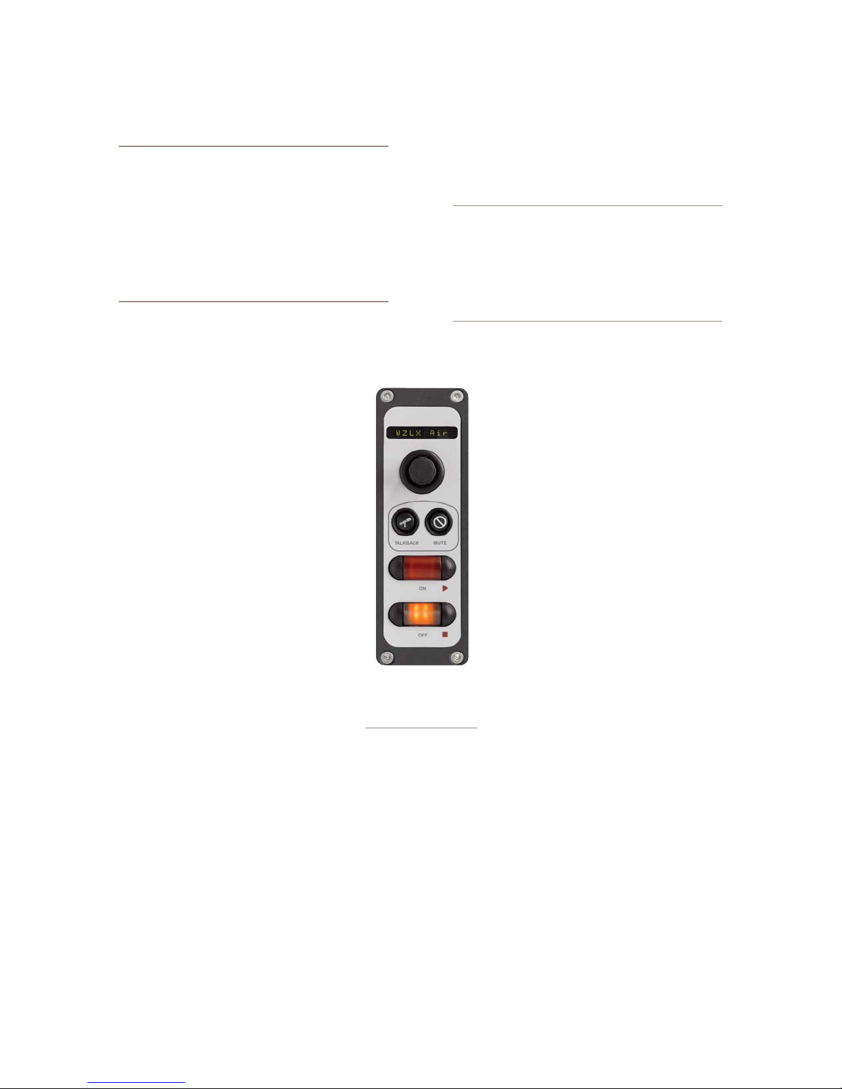
Individual Headphones Section
Note: These controls apply ONLY IF:
• The loaded source is a Mic-type source.
• The loaded source has an individual headphone feed associated with it.
• The position at which the mic is installed also
has an Element accessory panel that allows tal-
ent to select their own headphone feeds (such
as the one shown in Figure 5-2).
•
CURRENT SOURCE: The source currently specified
for monitoring in the Monitors page of
the Show Profile.
•
SOURCE FOR PRESET 1: Specify the
source that will load when the acces-
sory panel’s Ext 1 key is pressed.
•
SOURCE FOR PRESET 2: Specify the
source that will load when the acces-
sory panel’s Ext 2 key is pressed.
•
HEADPHONES MASTER GAIN: Spec-
ify the initial amount of gain that the
Individual Headphone Feed will have
when the Show Profile loads. Turn then
Off or Use up to 85 dB of cut.
menus, the Auxiliary Send Description Screen captures
the global Aux Send settings that can be set using the
Global Options Sends & Returns Key located on the
Master Module.
Note: Instead of the Retain Source Settings
option found in the Channel Descriptions pages,
the Auxiliary Send Descriptions Screen features
a new option: Retain Existing Settings. Using this option with any of the Aux Send/Return
settings allows the Show Prole to be loaded
without disturbing the Aux Send/Return master
settings in use by the board operator.
From the Show Profile Settings web
page, choose the Auxiliary Send/Return
Data link. You’ll find the following op-
tions:
Aux Send A / B / C / D Master Gain:
•
Selecting Off turns off master gain adjust-
ment for each Aux Send’s outbound feed.
Select Use and enter a gain value between
-25 dB and 10 db to trim overall gain if de-
sired, or select Retain Existing Setting.
Aux Send A / B / C / D On/Off Sta-
•
tus: Choose Off to turn the selected Aux
Send 1 off completely, On to turn it on, or
Retain Existing Setting.
Finishing Up...
Finally, there are two more controls at
the very bottom of the screen:
•
SAVE CHANGES button applies any changes made
to the current Channel Description. If you don’t click
this button, your changes won’t be saved!
•
BACK TO SHOW PROFILE link takes you back to
the Show Profile Settings menu.
The Auxiliary Send And Return
Description Screen
In the same way that the Show Profile Channel De-
scription screens mirror Element’s Channel Options
Figure 5-2: an
Element accessory
panel with headphone
selec tor
Use and enter a gain value between -25 dB and 10
db to trim overall return gain if desired, or select
Retain Existing Setting.
Aux Return 1 / 2 On/Off Status: Choose Off to
•
turn the selected Aux Return off completely, On to
turn it on, or Retain Existing Setting.
Aux Return 1 / 2 Signal Mode: Choose from
•
Stereo, Left (left channel fed to both sides), Right
(right channel fed to both sides), Sum (sum L+R to
mono and feed to both sides) or Retain Existing
Setting.
©2008 Axia Audio — Rev. 3.0
Aux Return 1 /2 Master Gain: Select-
•
ing Off turns off master gain adjustment
for the selected Aux Return bus. Select
5: Show Proles • 89
Page 100

5: Show Proles • 90
Aux Return 1 / 2 Panorama Setting: Trim Pan/
•
Balance for the selected Aux Return, or Retain Ex-
isting Setting.
Aux Return 1 / 2 Assign to PGM1 / PGM2 /
•
PGM3 / PGM4: Choose On to fold the selected Aux
Return into any of the four PGM buses, or choose
Retain Existing Setting.
Aux 1 / 2 Source ID: If this drop-down box looks
•
familiar, that’s because it’s just like the ones you
used earlier to construct Source Profiles and map I/O
to Axia Audio Nodes. Click in the box and select the
audio device that will be providing source audio for
the Aux 1 or Aux 2 Return.
Save Changes button applies any changes made to
•
the Auxiliary Send Description and returns you to
the Show Profile Settings menu.
Back to Show Prole link takes you back to Show
•
Profile Settings without saving changes.
Monitor Section Screen
The Monitor Section Data screen captures the Moni-
tor settings found in Element’s Monitor Options menus.
Since you’re working on a “captured” Show Profile, this
page will, of course, mirror the choices you made when
you set up Element in the beginning of this chapter.
From the Show Profile Settings web page, choose the
Monitor Section Data link (refer to Figure 5-4). You’ll
find the page divided into four sections: general options,
Control Room Monitor options, Control Room Head-
phone options, and Studio Monitor options.
General Monitor Options
TIMER MODE: Lets you decide globally how the
•
onscreen Count Up (event) timer will behave when
this profile is loaded:
Choose Manual to start, stop and reset the timer
»
by hand using the controls displayed when the
Timer Options key is pressed.
Choose Auto-Reset and the timer will automat-
»
ically reset to zero and begin counting whenever
a fader is turned On.
Choose Auto-Add to have the timer count up
»
when a fader is turned On and stop counting
when that source is turned Off. In this mode, the
timer will not reset to zero when it is restarted.
SHOW TENTHS ON: Allows you to set the Count-
•
down and Count Up timers to show or hide tenths of
a second displays. Choices are:
No Timers: tenths of a second are hidden on
»
both timers.
Down Timers: tenths are shown only on Count-
»
down timers.
Up Timers: tenths are shown only on Count Up
»
timers.
Both Timers: All timers display tenths of a sec-
»
ond readouts.
FADER MODE: Sets the fader behavior globally for
•
this Show Profile. Choose from:
Normal: faders are turned on and off manually.
»
Fader Start: faders turn on when the fader is
»
raised and off when it is lowered to ∞.
Retain Source Setting: Each individual fader
»
behaves as its Source Profile dictates.
PREVIEW INTERLOCK MODE: If Enable is chosen,
•
pressing any fader’s Preview key causes any other,
previously-lit Preview key to be extinguished, re-
moving that source from Preview. The board opera-
tor can assign multiple faders to Preview by push-
ing and holding any lit Preview key while pushing
other Preview keys to add or subtract.
If Disable is chosen, each Preview key works like
a press-on, press-off latching switch. Multiple fad-
ers can be assigned to Preview simply by pushing
once; a second push cancels any individual Preview
assignment.
SWITCHED METER SOURCE SELECT: Choose
•
whether the far-right on-screen meter bars will dis-
play levels for the PROGRAM (PGM-4) bus, the
source feeding the Control Room Monitors (Moni-
©2008 Axia Audio — Rev. 3.0
 Loading...