

Page 1
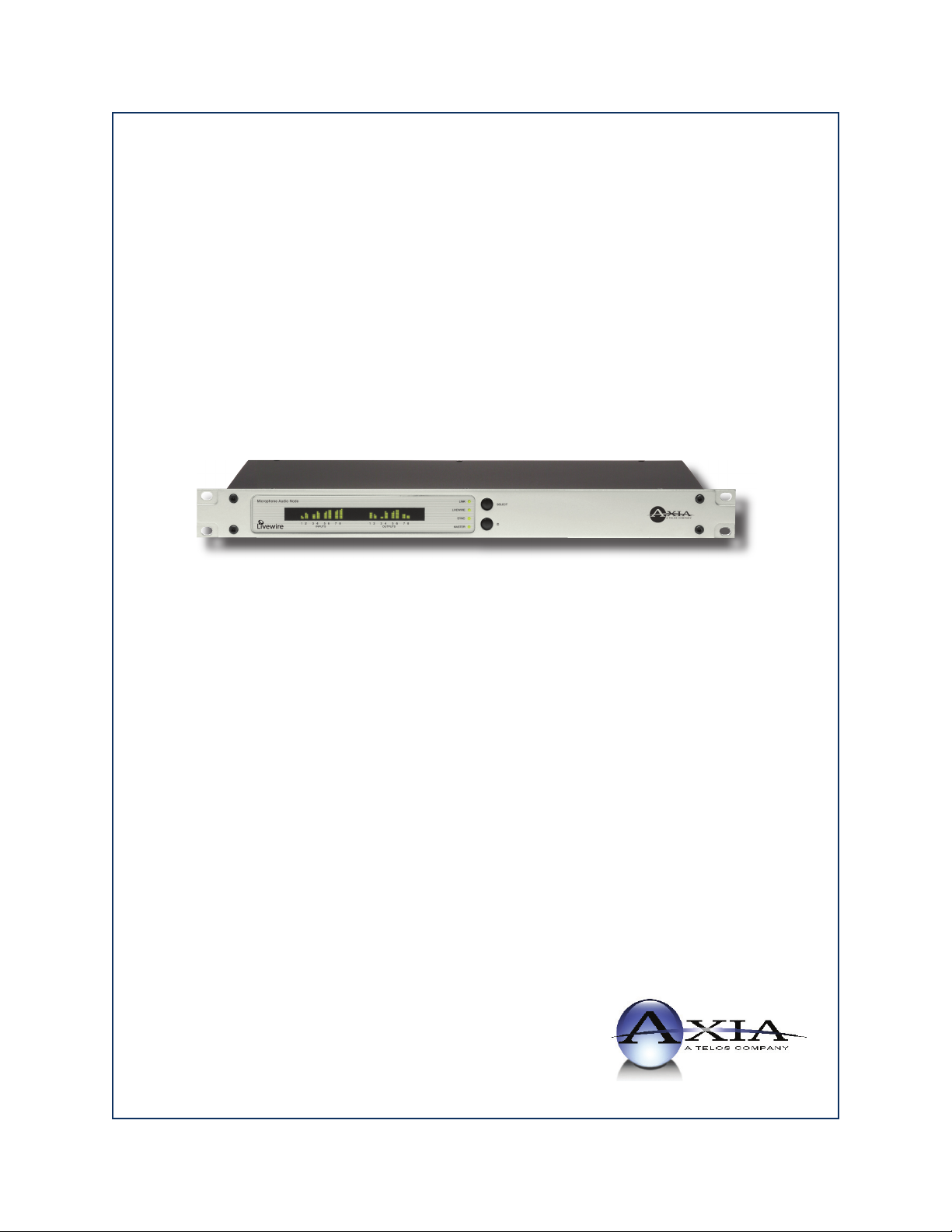
8x8 Analog Node
8x8 AES Node
Installation & User’s Guide
Version 2.0, February, 2007
Page 2

IMPORTANT NOTE:
Axia nodes are intended for use with an Ethernet
Switch that supports multicast and QOS (Quality
of Service). On a non-switched Ethernet hub, or a
switch that is not enabled for multicast, this will result in network congestion that could disrupt other
network activity. Should you wish to connect a node
to a non-Livewire network for access to the web configuration interface, etc, you must first confirm that
streaming is disabled as described in Section 2 page
6 “Programming the Node’s Streaming Mode”.
USA Class A Computing Device
Information To User. Warning:
This equipment generates, uses, and can radiate radio-frequency energy. If it is not installed and used
as directed by this manual, it may cause interference
to radio communication. This equipment complies
with the limits for a Class A computing device, as
specified by FCC Rules, Part 15, Subpart J, which
are designed to provide reasonable protection against
such interference when this type of equipment is operated in a commercial environment. Operation of
this equipment in a residential area is likely to cause
interference. If it does, the user will be required to
eliminate the interference at the user’s expense.
NOTE: Objectionable interference to TV or radio
reception can occur if other devices are connected to
this device without the use of shielded interconnect
cables. FCC rules require the use of only shielded
cables.
Canada Warning:
“This digital apparatus does not exceed the Class A
limits for radio noise emissions set out in the Radio
Interference Regulations of the Canadian Department of Communications.” “Le present appareil nu
merique n’emet pas de bruits radioelectriques depassant les limites applicables aux appareils numeriques
(de les Class A) prescrites dans le Reglement sur le
brouillage radioelectrique edicte par le ministere des
Communications du Canada.”
Important Safety Information
To reduce the risk of electrical shock, do not expose
this product to rain or moisture. Keep liquids away
from the ventilation openings in the top and rear of
the unit. Do not shower or bathe with the unit.
Caution
The installation and servicing instructions in the
manual are for use by qualified personnel only. To
avoid Electric Shock, do not perform any servicing
other than that contained in the operating instructions
unless you are qualified to do so. Refer all servicing
to qualified personnel.
Electrical Warning
To prevent risk of electric shock: Disconnect power
cord before servicing.
This equipment is designed to be operated from a
power source that includes a third “grounding” connection in addition to the power leads. Do not defeat
this safety feature. In addition to creating a potentially hazardous situation, defeating this safety ground
will prevent the internal line noise filter from functioning.
Ventilation Warning
The Axia 8x8 node uses convection cooling. Do not
block the ventilation openings in the side of the unit.
Failure to allow proper ventilation could damage the
unit or create a fire hazard. Do not place the unit on
a carpet, bedding, or other materials that could inter
fere with the rear and top panel ventilation openings.
-
-
Page 3

Customer Service
We support you...
By Phone/Fax in the USA.
Customer service is available from 9:30 AM to 6:00 PM USA Eastern Time, Monday through Friday at
•
+1 216.241.7225. Fax: +1 216.241.4103.
By Phone/Fax in Europe.
Service is available from Axia Europe in Germany at +49 81 61 42 467. Fax: +49 81 61 42 402.
•
By E-Mail.
The address is [email protected].
•
Via World Wide Web.
The Axia Web site has a variety of information which may be useful for product selection and support. The URL
•
is http://www.AxiaAudio.com.
Feedback
We welcome feedback on any aspect of Axia products or this manual. In the past, many good ideas from users have
made their way into software revisions or new products. Please contact us with your comments.
Updates
The operation of the Axia node is determined largely by software. Periodic updates may become available - to
determine if this is the case check our web site. Contact us to determine if a newer release is more suitable to your
needs.
Our electronic newsletter has announcements of major software updates for existing products, as well as keeping
you up to date on the latest Axia, Telos, and Omnia product releases. To subscribe go to:
http://www.axiaaudio.com/news/eNews.htm
Trademarks
Telos Systems, Axia Audio, Livewire, the Livewire Logo, the Axia logo, SmartSurface, SmartQ, Omnia, the
Omnia logo, and the Telos logo, are trademarks of TLS Corporation. All other trademarks are the property of their
respective holders.
Copyright © 2005 by TLS Corporation. Published by Axia Audio. We r eserve the right to make improvements or changes in the prod
ucts described in this manual, which may affec t the product specifications, or to revise the manual without notice. All rights reserved.
Axia Audio
2101 Superior Ave. Cleveland, OH 4 4114 USA
+1 (216) 241-7225
Axia Europe
Johannisstraβe 6, 85354 Freising, Germany
+49 81 61 42 467
-
Introduction • iii
Version 2.0, February, 2007
Page 4

Notice
About This Manual
All versions, claims of compatibility, trademarks, etc.
of hardware and software products not made by Axia
mentioned in this manual or accompanying material
are informational only. Axia makes no endorsement
of any particular product for any purpose, nor claims
any responsibility for operation or accuracy.
Warranty
This product is covered by a one year limited war-
ranty, the full text of which is included in the rear
section of this manual.
Service
You must contact Axia before returning any equip-
ment for factory service. Axia will issue a Return
Authorization number, which must be written on the
exterior of your shipping container. Please do not
include cables or accessories unless specifically re-
quested by the Technical Support Engineer at Axia.
Be sure to adequately insure your shipment for its
replacement value. Packages without proper authori-
zation may be refused. US customers please contact
Axia technical support at +1 (216) 241-7225. All oth-
er customers should contact their local representative
to arrange for service.
We strongly recommend being near the unit when
you call, so our Support Engineers can verify infor-
mation about your configuration and the conditions
under which the problem occurs. If the unit must
return to Axia, we will need your serial number, lo-
cated on the rear panel.
This manual covers the details of the Axia 8x8 Analog and 8x8 AES nodes. However it is assumed in
this document that you are familiar with Livewire’s
basic concepts, as outlined in the companion Introduction to Livewire: System Design Reference &
Primer manual.
If you have not done so, please review that material first. In it we explain the ideas that motivated
Livewire and how you can use and benefit from it,
as well as nitty-gritty details about wiring, connectors, and the like. Since Livewire is built on standard
networks, we also help you to understand general
network engineering so that you have the full background for Livewire’s fundamentals. After reading
Introduction to Livewire you will know what’s up
when you are speaking with gear vendors and the
network guys that are often hanging around radio
stations these days.
As always, we welcome your suggestions for im-
provement. Contact Axia Audio with your comments:
Axia Audio, a Telos Company
2101 Superior Avenue
Cleveland Ohio 44114 USA
Phone: +1.216.241.7225
Web: www.AxiaAudio.com
E-Mail: [email protected]
Introduction • iv
Version 2.0, February, 2007
Page 5

Table of Contents
Warranty . . . . . . . . . . . . . . . . . . . . . . . . iv
Service . . . . . . . . . . . . . . . . . . . . . . . . . iv
About This Manual
Notes From the Founder/CEO of Telos . . . . . . . .
A Note From The President of Axia
Chapter One:
Intoducing the 8x8 Analog and 8x8 AES nodes
Front Panel Controls and Indicators . . . . . . . . . . 1
Bargraph LED meters . . . . . . . . . . . . . . . . .
Rear Panel . . . . . . . . . . . . . . . . . . . . . . . 2
AC (Mains) Power. . . . . . . . . . . . . . . . . . . 2
Livewire (100 Base-T) Connector. . . . . . . . . . . 3
Input Connectors . . . . . . . . . . . . . . . . . . . 3
Output Connectors. . . . . . . . . . . . . . . . . . . 3
ChapterTwo:Operation via the 8x8 node’s front panel
CONFIGURATION & TESTING
Powering up . . . . . . . . . . . . . . . . . . . . . . 5
Restoring Defaults . . . . . . . . . . . . . . . . . . . 5
Bench Testing . . . . . . . . . . . . . . . . . . . . .
Basic Programming - via the front panel . . . . . . . 5
Chapter Three: Advanced Programming
Assigning an IP Address Remotely . . . . . . . . . .
Accessing the Node’s Web Pages . . . . . . . . . . .
Status LED indicators . . . . . . . . . . . . . . . 1
LINK . . . . . . . . . . . . . . . . . . . . . . . . 1
LIVEWIRE . . . . . . . . . . . . . . . . . . . . . 1
SYNC & MASTER . . . . . . . . . . . . . . . . . 1
SYNC & MASTER with the 8x8 AES Node
INPUT (Transmit to network) METERS . . . . . .
OUTPUT (Receive from network) METERS . . . .
Analog Output Characteristics . . . . . . . . . . . 4
AES Input Characteristics . . . . . . . . . . . . . 4
Programming the unit’s IP address
Checking the Livewire Node Name
Checking the Livewire Node Software Version
Programming the Node’s Streaming Mode
Programming the unit’s Transmit Base Channel
(TxBCH) . . . . . . . . . . . . . . . . . . . . . . 6
Programming the unit’s Receive Base Channel
(RxBCH) . . . . . . . . . . . . . . . . . . . . . . 7
. . . . . . . . . . . . . . . . . . iv
. . . . . . . . . . vii
. . . . . . 1
. . . . . 2
. . . . . . . . . . . 5
. . . . . . . . . 5
. . . . . . . . . 6
. . . 6
. . . . . 6
. . . . . . . . 9
The 8x8 node home page . . . . . . . . . . . . . . . 10
The Configure Sources (local inputs) page . . . . . .
Source Name and Channel
Gain (dB) . . . . . . . . . . . . . . . . . . . . . . 11
AES Mode . . . . . . . . . . . . . . . . . . . . . 11
vi
2
2
2
5
5
9
9
The Configure Destinations (local outputs) page . . .
Destination Name . . . . . . . . . . . . . . . . . 12
Destination Channel . . . . . . . . . . . . . . . . 12
Destination Type . . . . . . . . . . . . . . . . . .
Output Load . . . . . . . . . . . . . . . . . . . . 13
Listen Links. . . . . . . . . . . . . . . . . . . . . 13
The Surface Applications page
The Meters page . . . . . . . . . . . . . . . . . . . . 13
Meters Inputs . . . . . . . . . . . . . . . . . . . . 13
Meters Outputs . . . . . . . . . . . . . . . . . . . 13
The System Parameters page . . . . . . . . . . . . . 14
IP Settings . . . . . . . . . . . . . . . . . . . . . . .
Host name . . . . . . . . . . . . . . . . . . . . . 14
Network address (IP Address) . . . . . . . . . . .
Netmask (Subnet mask). . . . . . . . . . . . . . . 14
Gateway (Router). . . . . . . . . . . . . . . . . . 14
Syslog IP Address
Syslog Severity Level Filter . . . . . . . . . . . . 15
User password . . . . . . . . . . . . . . . . . . . . . 15
Firmware version . . . . . . . . . . . . . . . . . . . 16
Saving Bank 1 Software
Downloading new software
The Network & QOS page . . . . . . . . . . . . . . 17
Livewire Clock Master . . . . . . . . . . . . . . . . 17
Livewire Clock Mode . . . . . . . . . . . . . . . . . 17
Receive Buffer Size . . . . . . . . . . . . . . . . . .
801.1p tagging VLAN ID, 802.1q Priority, & DSCP Class
Of Service . . . . . . . . . . . . . . . . . . . . . . . 17
AES Synchronization and Clock . . . . . . . . . . . 18
AES Synch Source & AES Master Timebase . . . .
AES Output Sync . . . . . . . . . . . . . . . . . . 18
APPENDICES . . . . . . . . . . . . . . . . . . . . . . 19
Unbalanced Connections . . . . . . . . . . . . . . . 19
Unbalanced Destinations. . . . . . . . . . . . . . 19
Sources . . . . . . . . . . . . . . . . . . . . . . .
Using Axia Node With Ethernet Radios
Specifications & Warranty
AXIA Node LIMITED WARRANTY
. . . . . . . . . . . . . . . . . 15
. . . . . . . . . . . . . 10
. . . . . . . . . . . . 13
. . . . . . . . . . . . . . 17
. . . . . . . . . . . . 17
. . . . . . 20
. . . . . . . . . . . . . . . . 18
. . . . . . . . . 19
10
12
12
14
14
17
18
19
Introduction • v
Version 2.0, February, 2007
Page 6

A Note From The Founder/CEO of Telos
add an Ethernet switch and more interfaces to build a
system with as many inputs and outputs as you want.
It’s been a tradition since Telos’ very first product, the
Telos 10 digital phone system, that I share a few words
with you at the beginning of each manual. So here goes.
In radio broadcast studios we’re still picking up the
pieces that have fallen out from the digital audio revo-
lution. We’re not using cart machines anymore because
PCs are so clearly a better way to store and play audio.
We’re replacing our analog mixing consoles with digi-
tal ones and routing audio digitally. But we’re still using decades-old analog or primitive digital methods to
connect our gear. Livewire has been developed by Telos
to provide a modern PC and computer network-oriented
way to connect and distribute professional audio around
a broadcast studio facility.
Your question may be, “Why Telos? Don’t you guys
make phone stuff?” Yes, we certainly do. But we’ve al-
ways been attracted to new and better ways
to make things happen in radio facilities. And
we’ve always looked for opportunities to make
networks of all kinds work for broadcasters.
When DSP was first possible, we used it to fix
the ages-old phone hybrid problem. It was the
first use of DSP in radio broadcasting. When
ISDN and MP3 first happened, we saw the
possibility to make a truly useful codec. We were the
first to license and use MP3 and the first to incorporate
ISDN into a codec. We were active in the early days of
internet audio, and the first to use MP3 on the internet.
Inventing and adapting new technologies for broadcast
is what we’ve always been about. And we’ve always
been marrying audio with networks. It’s been our passion right from the start. In our genes, if you will. As a
pioneer in broadcast digital audio and DSP, we’ve grown
an R&D team with a lot of creative guys who are openeyed to new ideas. So it’s actually quite natural that we
would be playing marriage broker to computer networks
and studio audio.
Audio may be routed directly from interface to interface or to other PCs, so you now have an audio routing
system that does everything a traditional “mainframe”
audio router does – but at a lot lower cost and with a lot
more capability. Add real-time mixing/processing engines and control surfaces and you have a modern studio
facility with many advantages over the old ways of doing
things. OK, maybe this is not as thrilling as a wedding
night – perhaps kissing your first lover is a better analogy. (By the way, and way off-topic, did you know that
the person you were kissing was 72.8% water?)
While we’re on the subject of history… you’ve prob
ably been soldering XLRs for a long time, so you feel a
bit, shall we say, “attached” to them. We understand. But
no problem – you’ll be needing them for microphones
for a long while, so your withdrawal symptoms won’t be
serious. But your facility already has plenty
of Ethernet and plenty of computers, so you
probably already know your way around an
RJ-45 as well. It’s really not that strange to
imagine live audio flowing over computer networks, and there’s little question that you are
going to be seeing a lot of it in the coming
years.
The 20th century was remarkable for its tremendous
innovation in machines of all kinds: power generators,
heating and air conditioning, cars, airplanes, factory automation, radio, TV, computers. At the dawn of the 21
it’s clear that the ongoing digitization and networking of
text, audio, and images will be a main technology story
for decades to come, and an exciting ride for those of us
fortunate to be in the thick of it.
Speaking of years, it has been a lot of them since I
wrote the Zephyr manual intro, and even more since the
Telos 10 – 20 years now. Amazing thing is, with all the
change around us, I’m still here and Telos is still growing
in new ways. As, no doubt, are you and your stations.
-
st
,
What you get from this is nearly as hot as a couple
on their wedding night: On one RJ-45, two-way multiple
Steve Church
audio channels, sophisticated control and data capability, and built-in computer compatibility. You can use
Livewire as a simple sound card replacement – an audio
Introduction • vi
interface connecting to a PC with an RJ-45 cable. But
Version 2.0, February, 2007
Page 7
A Note From The President of Axia
20 years ago, I designed my first broadcast console
for PR&E. I look back on that time with great fondness;
we were building bullet-proof boards for the world’s
most prestigious broadcasters, making each new console
design bigger and fancier to accommodate a wider variety of source equipment and programming styles. The
console was the core of the studio; all other equipment
was on the periphery.
Then things changed: the PC found its way into broadcast audio delivery and production. At first, PC audio
applications were simple, used only by budget stations
to reduce operating expenses. But soon the applications
evolved and were embraced by larger stations. Slowly,
the PC was taking center stage in the radio studio.
Like many, I was captivated by the PC. Stations
retired carts, phonographs, open-reel decks, cassettes
— even more modern digital equipment such
as DAT and CD players, replacing all with PC
apps. Client/server systems emerged and entire facilities began using PCs to provide most
– or all – of their recorded audio. Yet consoles
continued to treat PCs as nothing more than
audio peripherals. I knew that we console designers were going to have to rethink our designs to deal with computer-centric studios.
During this time, traditional broadcast console companies began producing digital versions. But early digi
tal consoles were nearly identical in form and function
to their analog predecessors. It took a fresh look from a
European company outside broadcasting to merge two
products – audio routing switchers and broadcast con
soles – into a central processing engine and attached
control surface. Eventually nearly every console and
routing switcher company followed suit, and a wide variety of digital “engines” and control surfaces flooded
the market.
But, advanced as these integrated systems were, they
still handled computer-based audio sources like their
analog ancestors. Sure, the router and console engine
were now integrated, but the most important studio ele
ment – the PC – was stuck in the past, interfaced with
100-year-old analog technology. The PC and console
couldn’t communicate in a meaningful way – strange,
considering that PCs everywhere were being networked,
fast becoming the world’s most popular and powerful
communication tool.
Then a group of Telos engineers developed a method
of using Ethernet to network real-time audio devices, allowing computers and consoles, controllers and peripherals to interact smoothly and intelligently. Powerful, flexible networks had finally come to our studios. As with
the transition from carts to computers, the benefits are
many and impressive. A few networked components can
replace routing switchers, consoles, processing peripherals, sound cards, distribution amps, selector switches
and myriad related devices.
This deceptively simple networked system costs a
fraction of other approaches, yet has capabilities surpassing anything else. The system is modular and can
be used to perform discrete functions in a traditional
environment. Concurrently, it easily scales to serve both
the humblest and the very largest of facilities.
Console, router, and computer work in harmony.
So, equipped with this new technology
and countless ideas, we launch Axia, the newest division of Telos. Axia is all about delivering innovative networked audio products to
future-minded broadcasters. On behalf of our
entire team, I welcome you as a charter client. Axia is
the culmination of nearly 40 man-years of some of the
-
most ambitious R&D ever applied to the radio industry.
And this is only the beginning. We have more products,
innovations, and partnerships in the pipeline.
You already know your Axia system is unlike any-
-
thing else. So it shouldn’t be surprising that your new
system is loaded with new thinking, new approaches,
and new ideas in virtually every conceivable area. Some
concepts will challenge your traditional ideas of studio
audio systems, but we’re certain that once you have experienced the pleasures of the networked studio, you’ll
never want to go back. And now, for something completely different...
-
Michael “Catfish” Dosch
Introduction • vii
Version 2.0, February, 2007
Page 8

Introduction • viii
Version 2.0, February, 2007
Page 9
Chapter One:
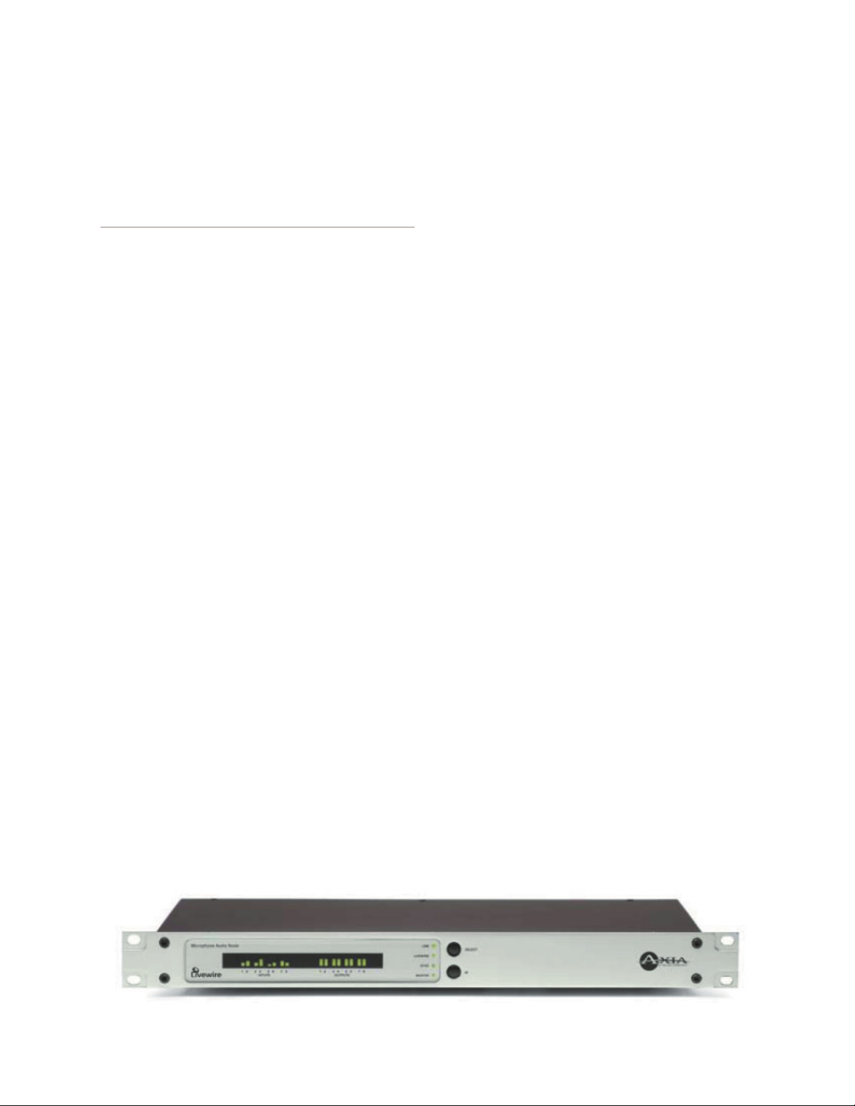
The Livewire 8x8 Audio Node incorporates a number
of front panel indicators to allow the operator to verify
proper operation quickly and confidently.
Introducing the 8x8 Analog
and 8x8 AES Nodes
This section will allow you to get to know the 8x8
Node and describes the unit’s features, display, and connectors.
Description
The Axia Livewire 8x8 Audio Node has eight stereo
inputs, and eight stereo outputs. 8x8 Analog nodes have
balanced analog inputs and outputs whereas the 8x8
AES nodes have AES3 inputs and outputs. Therefore,
each 8x8 Node can create 8 stereo Livewire streams,
each of which becomes available to other devices on the
Livewire network.
Each stereo output can be assigned to output a stereo
Livewire stream acquired from the network.
Basic point-to-point (e.g. “Livewire Snake”) appli
cations require only two Livewire nodes and a category
6 “Crossover Ethernet cable”. More sophisticated multipoint networks can be used by connecting multiple
Livewire nodes to an appropriate Ethernet Switch.
NOTE: Only an approved, and properly programmed
Ethernet switch, incorporating the proper Multicast and
QoS standards may be used.
Status LED indicators
Four LEDs indicate the status of the Livewire and
Ethernet connections, as well as system synchronisation
as follows:
LINK
When illuminated continuously, this LED represents
the presence of a live Ethernet link to another Ethernet
100 Base-T device. This LED indicates that a connection is present and some device is connected. It does not
indicate the quality of the connection however. If no Eth
ernet link is present, this will flash slowly.
LIVEWIRE
This LED indicates that the connected Ethernet segment has Livewire traffic present. If the link LED is illuminated, and the LIVEWIRE LED fails to illuminate,
there are either no other Livewire devices connected, or
the Ethernet switch has not been programmed to pass
such traffic to the port to which this node is connected.
-
SYNC & MASTER
Only one of these two LEDs should be illuminated,
with the one exception noted below. If neither LED il
luminates, something is not correct. The SYNC LED
indicates the receipt of clock information from another
(Master) Livewire Node. The MASTER LED indicates
that this node is acting as the master clock source for the
Livewire network. More specifically:
-
-
Front Panel Controls and Indicators
Version 2.0, February, 2007
SYNC – If Sync packets are being received by the
Livewire node, this LED will begin to flash. The LED
will continue to flash until the Livewire node has locked
1: Introducing the 8x8 AES Nodes • 1
Page 10
its local clock to the network master. Once the local
node’s PLL is locked, the LED will illuminate solidly.
MASTER – The Livewire system employs a sophis
ticated master/slave clocking system over the Ethernet
network. By default any device may become the clock
master, however this can be changed if desired. The sys
tem has the ability to automatically change to a different
clock master should the current master become disconnected, or otherwise inoperable. This happens transparently without audio glitches. This LED indicates that this
node is currently acting as MASTER.
channels of each input. The meters are continuously
active, and indicate that audio is present at the associated input. The lowest LED segment will illuminate at
a signal level of -42 dBfs. The top-most LED segment
represents a level of 0 dBfs – this segment should not illuminate except in cases of extreme input overload.
-
OUTPUT (Receive from network) METERS
The rightmost 8 LED meter pairs represent the left
and right channels of each audio stream being received.
Each meter is associated with the audio on the corresponding output. The meter calibration is the same as
for the input meters.
SYNC & MASTER with the 8x8 AES Node
When the AES Node is used in the default configura
tion the SYNC and MASTER LEDs operate as described
above. However, if the AES sync input as Livewire master timebase is set to YES from the QOS web pages (see
section 3, Advanced Programming) these lights will operate differently, as described here:
SYNC – If a valid AES signal received by the AES
input designated as AES sync source in the QOS web
page, this LED will begin to flash. The LED will con-
tinue to flash until the Livewire node has locked its
local clock to the AES input signal. Once the local
node’s PLL is locked, the LED will illuminate sol-
idly.
MASTER – This LED indicates that this node is
currently acting as MASTER clock source for the
Livewire network.
Bargraph LED Meters
The Livewire 8x8 nodes have a bargraph meter for
each input and each output.
INPUT (Transmit to network) METERS
The left eight meter-pairs represent the left and right
The lowest Output LED segment has a special mean-
-
ing. These LEDs will be illuminated whenever the stream
designated for that channel is present, and the Livewire
node is locked to that stream. Therefore, the lowest LED
segment will be illuminated during silence, to indicate
that the associated Livewire stream is correctly being
received.
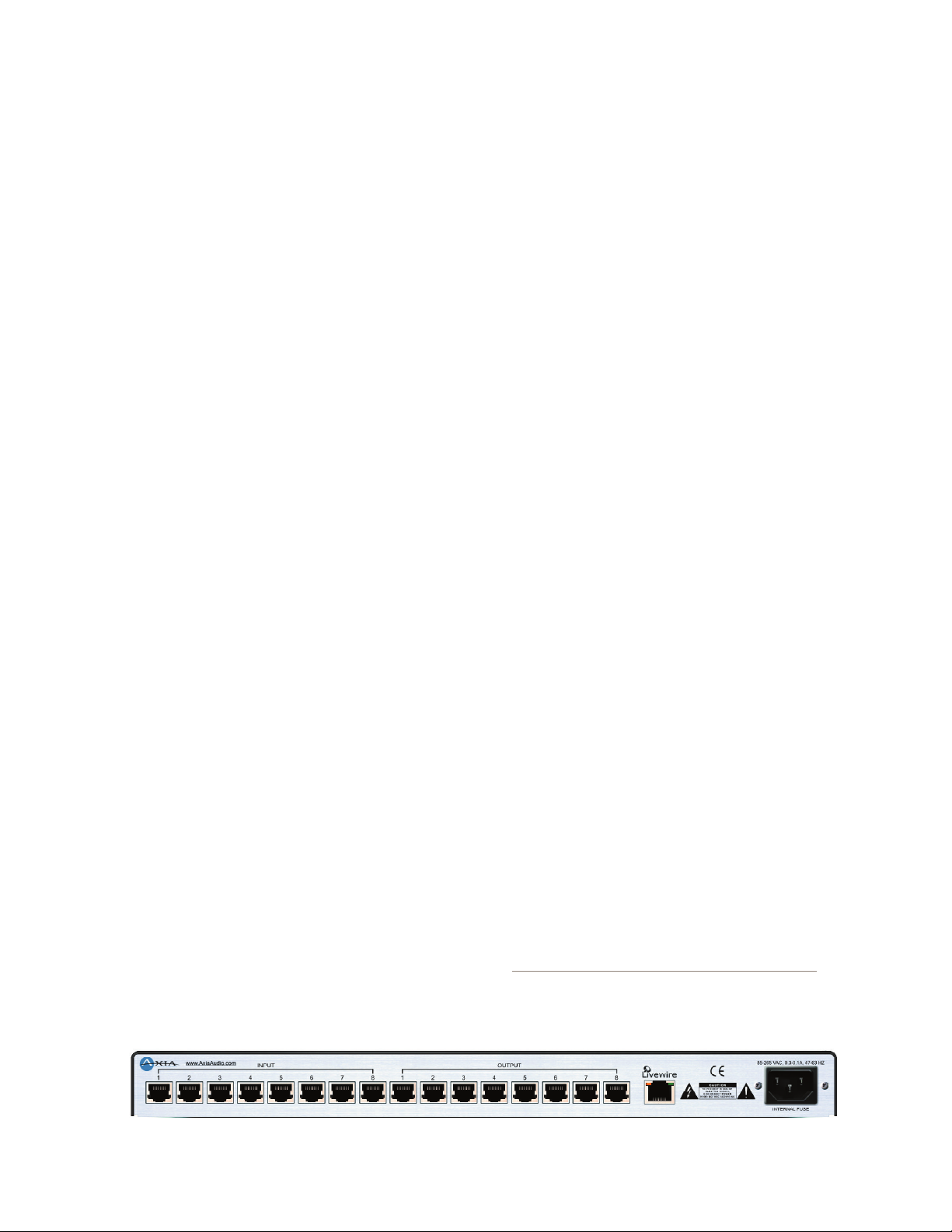
Rear Panel
The rear panel of both the 8x8 Analog Node and the
8x8 AES Node are essentially identical and are pictured
below:
AC (Mains) Power
The AC receptacle connects mains power to the
unit with a standard IEC (International Electrotechnical Committee) power cord. The power supply has a
“universal” AC input, accepting a range from 85 to 265
VAC, 47-63 Hz. A fuse is located inside on the power
supply circuit board
IMPORTANT! As with any piece of modern elec-
tronic gear, it is advisable that precautions
be taken to prevent damage caused by power
1: Introducing the 8x8 AES Nodes • 2
Version 2.0, February, 2007
Page 11
81
surges. Standard line surge protectors can be
used to offer some degree of protection. It is
the user’s responsibility to ensure protection
adequate for their conditions is provided. This
equipment is designed to be operated from a
power source, which includes a third “grounding” connection in addition to the power leads.
Do not defeat this safety feature. In addition to
creating a potentially hazardous situation, de
feating this safety ground will prevent the in
ternal line noise filter from functioning. If fuse
replacement is required, please note: For con
tinued protection against fire, replace fuse only
with same type and value. See the DETAILED
TECHNICAL INFORMATION section for informa
tion and cautions.
-
-
-
-
INPUT CONNECTORS
Pin Function: Analog/AES
1 Left Channel Input + /AES +
2 Left Channel Input - /AES -
3 Right Channel Input +
4 Not Connected
Livewire (100 Base-T) Connector
This connector is for connection to another Livewire
node, or an approved Ethernet switch. It has two integral
LEDs. The green “Link” LED indicates the presence of
a live signal (same as the front panel “Link” LED). The
“Activity” LED indicates that Ethernet packets are being
sent or received over the link.
IMPORTANT NOTE: Axia nodes are intended for
use with an Ethernet Switch that supports mul
ticast and QOS (Quality of Service). On a non-
switched Ethernet hub, or a switch that is not
enabled for multicast, this will result in network
congestion that could disrupt other network
activity. Should you wish to connect a node to
a non-Livewire network for access to the web
configuration interface, etc, you must first con
firm that streaming is disabled as described
in Section 2 page 6 “Programming the Node’s
Streaming Mode”.
-
-
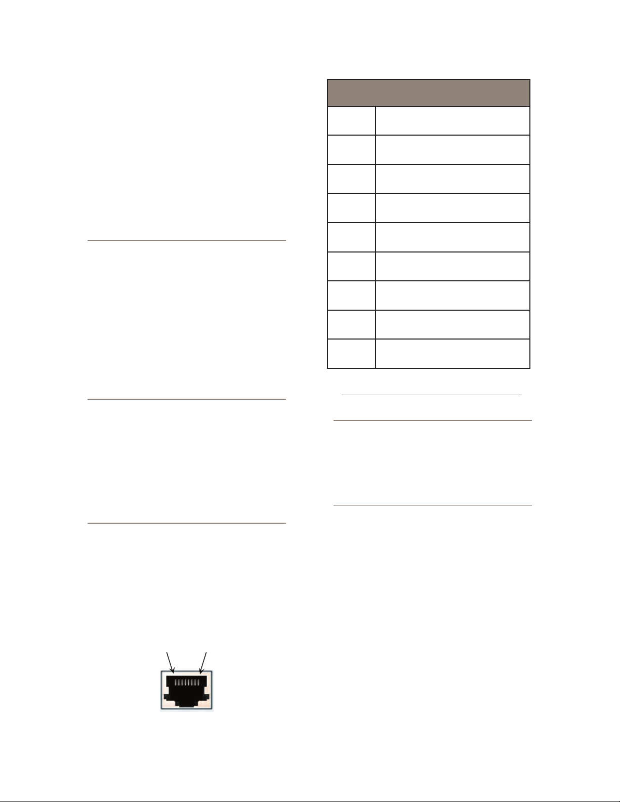
Input Connectors
Each pair of audio inputs share a 8-position / 8-pin
miniature modular jack (e.g. RJ45 style). The connector
pin functions are the same for both the AES and Analog
nodes and are as follows:
5 Not Connected
6 Right Channel Input -
7 Not Connected
8 Not Connected
AES Input Charac teristics AES3/EBU Compliant
IMPORTANT NOTE: Axia recommends using balanced audio connections for analog audio con
nections. If unbalanced sources are to be con
nected to these inputs, we strongly recommend
using a balanced to unbalanced buf fer amplifier
(or transformer) at the source device. Such devices are readily available, for example the Stu
dio Hub “Match Jack – Output”.
Analog Input Characteristics
Level: +4 dBu nom (+24 dBu clip point)
Impedance : >/= 10 K_
For additional technical information please see the
Specifications section.
-
-
-
Output Connectors
Each pair of audio outputs share a 8-position / 8 pin
miniature modular jack (e.g. RJ45 style). The connector
pin functions are the same for both the AES and Analog
nodes (see above).
Version 2.0, February, 2007
1: Introducing the 8x8 AES Nodes • 3
Page 12

IMPORTANT NOTE: Axia recommends using
balanced audio connections for analog audio
connections. If unbalanced devices are to be
connected to these outputs, we strongly recommend using a balanced to unbalanced buf
fer amplifier (or transformer) at the destination
device. Such devices are readily available, for
example the Studio Hub “Match Jack – Input”.
Analog Output Characteristics
Level – +4 dBu (+24 dBu clip point)
•
Impedance – < 50 _
•
AES Input Characteristics
Balanced 110 _ (XLR)
•
AES3/EBU Compliant
•
-
1: Introducing the 8x8 AES Nodes • 4
Version 2.0, February, 2007
Page 13

Chapter Two:
Operation via the 8x8 node’s
front panel
Here we cover everything you need to know to cre-
ate a simple Livewire snake using only the unit’s front
panel.
Configuration & Testing
Basic configuration of the Livewire node can be per-
formed from the front panel. In addition, the system can
be configured over the network by using a web browser
accessing the node’s built in web server, see section 3
Advanced Programming.
Powering up
When the Livewire node is powered on, you should
observe the following: The 4 LED indicators should il-
luminate briefly, and the LED meter display will display
a screen test. Next, you should see the node’s name dis
played (default name is “LiveIO”). After a brief period
of time, you will see the normal front panel bargraph
meter display (see section 1, above).
Restoring Defaults
To restore the Livewire node to the default settings
follow the steps below:
Bench Testing
Two Livewire nodes may be connected together in
“Point to point” mode (e.g. Ethernet snake mode) to ver-
ify operation of the units. When connected in this way
the audio fed to “input 1” of “node A” will be output on
“output 1” of “node B” whereas the audio on “input 1” of
“node B” will be output on “output 1” of “node A”. Like-
wise, the other inputs for the two nodes will be mapped
correspondingly. To connect two units in “point to point”
fashion follows these steps:
Restore default settings on both of the Livewire nodes
1.
to be connected. See “Restore Defaults”, above.
Enable streaming on each unit as follows: Press the
2.
<SELECT> button repeatedly until MODE is dis-
played. Press and hold the <ID> button until a cursor appears under the current setting (e.g. Off). Press
<SELECT> repeatedly until SNAKE is displayed.
Press <ID> to confirm your entry.
Connect the two units using a “Crossover 10/100
3.
Base-T” Category 6 cable 100 meters maximum (see
Introduction to Livewire; System Design Reference
& Primer).
The LINK and LIVEWIRE LEDs should illuminate
4.
on both nodes. The MASTER LED should illuminate
-
on one unit and the SYNC LED should illuminate on
the other unit.
The eight receive (output) meters on each of the two
5.
units should show the lowest segment illuminated to
indicate streams are being received.
6.
Audio may now be fed into each input and will be re
cieved on the corresponding output of the other unit.
Basic Programming - via the front panel
-
1.
Power the node OFF.
2.
Depress and hold the SELECT and ID buttons.
3.
Power ON the unit while continuing to hold the
above buttons.
4.
After about 8 seconds will see the word “RESET 3
S” displayed. If you release the buttons within 3 sec
onds no changes will occur. If you continue to hold
the buttons after 3 seconds the default settings will
be set and “REBOOT” will be displayed. At this time
release the SELECT and ID buttons.
Version 2.0, February, 2007
Basic programming of the Livewire node can be
accomplished using the front panel display and the SE
LECT and ID buttons. The node’s name and other information can also be checked from the front panel.
-
Programming the unit’s IP address
Each Livewire node must have a unique IP address.
The only exception is when two nodes are connected in
the point-to-point (snake) configuration.
-
2: Operation Via the 8x8's Front Panel • 5
Page 14

2: Operation Via the 8x8's Front Panel • 6
To program the node’s IP address follow these steps:
Starting from the metering screen, press the
1.
<SELECT> button once. The default IP address is
“0.0.0.0”, so unless the unit has previously been pro-
grammed, the screen will show “000.000.000.000”.
Press and hold the <ID> button for 4 seconds. A
2.
blinking cursor will appear below the first digit. Use
<SELECT> to change the digit indicated by the cur
sor (each press of this number will increment the displayed digit by one).
Press the <ID> button to jump to the next digit. Use
3.
<SELECT> to change the digit indicated by the cur-
sor. Continue until all digits of the IP address have
been entered.
4.
Once the changes are complete, press the <ID> button repeatedly until no cursor is shown then press
<SELECT> to exit.
If you do not wish to save your changes do not press
5.
<SELECT> after reaching the last digit. After ap-
proximately 10 seconds the display will return to
the meter screen and the previous settings will be
restored.
Checking the Livewire Node Name
With the meter screen displayed, press SELECT
twice. The name of this Livewire node will be displayed.
The default is LiveIO. To change the name of a node you
must use the Browser interface, see section 3 Advanced
Programming.
Checking the Livewire Node Software Version
With the meter screen displayed, press SELECT three
times. The software version will be will be displayed.
Programming the Node’s Streaming Mode
The streaming mode can be selected from the front
panel. The default mode is to have streaming disabled
(e.g. OFF), thereby allowing safe connection to a com
puter or LAN for programming. See the Introduction to
Livewire; System Design Reference & Primer manual
for more on streaming. The possible settings for stream
ing mode are shown here:
•
OFF – This disables both streaming of Livewire au
dio and Livewire clock packets. This setting is useful
when you wish to connect the unit to a non-Livewire
LAN or directly to a computer to configure the IP
address and other settings.
•
FAST – This enables Fast Stream generation and
also permits clock packet generation. This is the
typical setting for most Livewire audio network ap-
-
plications.
•
SLOW – This enables Slow Stream generation as
well as Livewire clock packets. This is the usually
•
setting for a Axia node used in conjunction with a
computer or other device where delay is unimportant.
•
SNAKE – The mode is appropriate for when two
Axia nodes are directly connected with a null Eth
ernet cable. This enables Livestreams and Livewire
clock packets only. SNAKE mode differs from fast
by disallowing local loopback capability in the node.
•
CUSTOM – This indicates that the Streaming Mode
parameters have been configured using the unit’s
web page interface.
To change the Streaming Mode from the front panel
follow these steps:
Press the <SELECT> button repeatedly until MODE
1.
is displayed.
Press and hold the <ID> button until a cursor appears
2.
under the current setting.
3.
Press <SELECT> repeatedly until SNAKE is dis
played.
Press <ID> to confirm your entry.
4.
Programming the unit’s Transmit Base Channel
(TxBCH)
The Transmit Base Channel is the number assigned
to the first of the eight streams to be transmitted by this
unit. If the Transmit Base Channel is set to 00101 then
the system’s eight streams would be on channel numbers
101 through 108. Non-contiguous numbering is possible,
-
however in that case they must be assigned using the
node’s browser user interface, see section 3 Advanced
Programming.
-
-
-
-
Version 2.0, February, 2007
Page 15

If you have read the Introduction to Livewire; System Design Reference & Primer manual, you will know
that no each stream must have a unique channel number,
so don’t forget that now.
To program the node’s Transmit Base Channel fol-
low these steps:
Starting from the metering screen, press the <SE
1.
LECT> button 5 times. The default TxBCH is
“00001”, so unless the unit has previously been pro
grammed, the display will show that entry.
Press and hold the <ID> button for 4 seconds. A
2.
blinking cursor will appear below the first digit. Use
<SELECT> to change the digit indicated by the cur-
sor (each press of this number will increment the displayed digit by one).
Press the <ID> button to jump to the next digit. Use
3.
<SELECT> to change the digit indicated by the cur-
sor. Continue until all digits of the TxBCH have been
entered.
Once the changes are complete, press the <ID> but-
4.
ton repeatedly until no cursor is shown then press
<SELECT> to exit.
5.
If you do not wish to save your changes do not press
<SELECT> after reaching the last digit. After ap
proximately 10 seconds the display will return to the
meter screen and the old settings will be restored.
-
-
-
To program the node’s Receive Base Channel follow
these steps:
Starting from the metering screen, press the <SE
1.
LECT> button 6 times. The default RxBCH is
“00001”, so unless the unit has previously been pro
grammed, the screen will show that entry.
Press and hold the <ID> button for 8 seconds. A
2.
blinking cursor will appear below the first digit. Use
<SELECT> to change the digit indicated by the cur-
sor (each press of this number will increment the displayed digit by one).
Press the <ID> button to jump to the next digit. Use
3.
<SELECT> to change the digit indicated by the cur-
sor. Continue until all digits of the TxBCH have been
entered.
Once the changes are complete, press the <ID> but-
4.
ton repeatedly until no cursor is shown then press
<SELECT> to exit.
5.
If you do not wish to save your changes do not press
<SELECT> after reaching the last digit. After ap
proximately 10 seconds the display will return to the
meter screen and the old settings will be restored.
-
-
-
Programming the unit’s Receive Base Channel
(RxBCH)
The Receive Base Channel is the number assigned to
the first of the eight streams to be received by this node
and output from its audio connectors. If the Receive Base
Channel is set to 00201 then the system will search the
Livewire network for eight streams on channel numbers
00201 through 00208. If a designated stream(s) is(are)
present the node will indicate this by illuminating the
lowest LED segment on the corresponding output meter.
Of course in many scenarios you will want to use non-
contiguous numbering for receive channels; these must
be assigned using the node’s web interface, see section 3
Advanced Programming.
Version 2.0, February, 2007
2: Operation Via the 8x8's Front Panel • 7
Page 16

2: Operation Via the 8x8's Front Panel • 8
Version 2.0, February, 2007
Page 17

Accessing the Node’s Web Pages
Chapter Three:
Advanced Programming
Using the node’s built in web pages to configure
advanced features is fast and easy.
Assigning an IP Address Remotely
If you have not assigned an IP address you must do
so. You can do this from the front panel as described in
section 2, or the node’s IP address can be remotely assigned over the network using a program included with
the your node called BootP. To do so follow these steps:
Start bootps.exe program on any Windows 2000/XP
1.
2.
Hit ID button on GPIO front panel.You will be
prompted for new IP address entry:
Enter new IP address and press ENTER:
3.
IMPORTANT NOTE: Axia nodes are intended for
use with an Ethernet Switch that supports mul
ticast and QOS (Quality of Service). On a non-
switched Ethernet hub, or a switch that is not
enabled for multicast, this will result in network
congestion that could disrupt other network
activity. Should you wish to connect a node to
a non-Livewire network for access to the web
configuration inter face, etc, you must first con
firm that streaming is disabled as described
in Section 2 page 6 “Programming the Node’s
Streaming Mode”.
Make note of the IP address you have entered, so that
you can access the Node using a Web browser, see sec
tion 3. You can now continue to assign additional Node
IP addresses, or shut down the Bootp program.
-
-
-
IMPORTANT NOTE: Axia nodes are intended for
use with an Ethernet Switch that supports mul
ticast and QOS (Quality of Service). On a nonswitched Ethernet hub, or a switch that is not
enabled for multicast, this will result in network
congestion that could disrupt other network
activity. Should you wish to connect a node to
a non-Livewire network for access to the web
configuration inter face, etc, you must first con
firm that streaming is disabled as described
in Section 2 page 6 “Programming the Node’s
Streaming Mode”.
A number of parameters may be configured using the
Livewire nodes built in web pages. To access the built
in web server from a computer, the computer and node
must be connected to the same LAN (or the computer
and node can be connected using a “crossover 10/100
Base-T” Ethernet cable). To connect enter the following
in your browser:
http://123.456.789.101
where “123.456.789.101 is the IP address if the node
to be configured.
Your browser should now display the login window
to allow you to access the node:
Enter a valid user name and password and click on
“OK” to log in.
•
The default user name for all Axia nodes is: “user”
•
The default password for all Axia nodes is: <enter>
NOTES:
The IP range (e.g. the first three numbers of the four
•
numbers of the IP address of the computer and the
node must match, or additional configuration and
router will be required.
Microsoft Internet Explorer version 5 and later have
•
been tested with the Livewire 8x8 Nodes. Other
browsers may work, however they have not been
tested.
Your browser must have Java enabled and must allow
•
“pop up” windows.
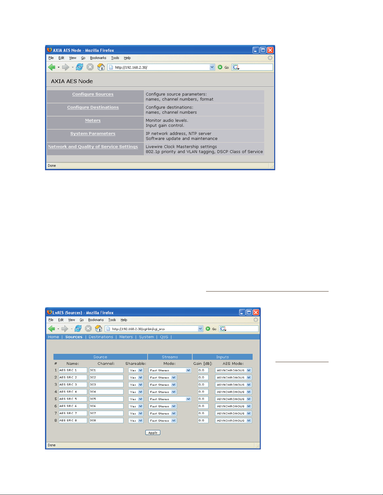
Once you have logged in you will see the Axia 8x8
•
node home page as shown here:
-
-
3: Advanced Programming • 9
Version 2.0, February, 2007
Page 18
The 8x8 Node Home Page
The home page simply acts as a homepage, to allow
access to each of the configuration pages. We describe
each of those pages in detail.
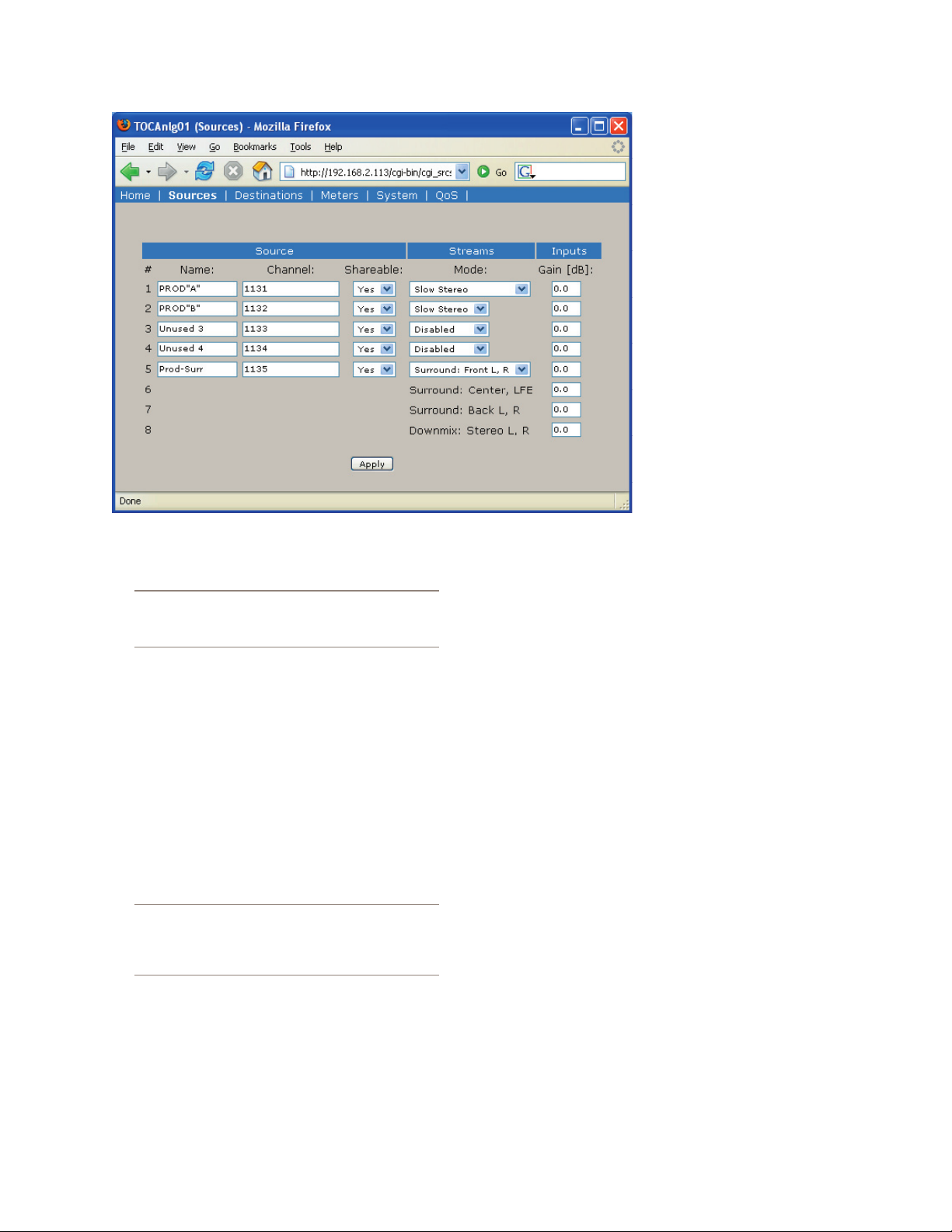
The Configure Sources (local inputs) page
This is where you configure the local inputs to this
node, and assign Livewire channels and parameters to
each. Once configuration is complete (or at any time in
the configuration process) click on Apply to save your
changes to the node.
The Sources screen
for the 8x8 Analog
and 8x8 AES nodes
are slightly differ
ent. The Analog 8x8
Node Sources screen
is shown:
Source Name and
Channel
As described in
the Introduction to
Livewire; System
Design Reference &
Primer manual, each
Livewire stream must
be assigned a unique channel number. The channel number must be a number between 1 and 32767. Optionally
a text name can be entered.
Livewire names may contain any printable character and can be up to 24 characters long (when entering
names excess characters will be truncated to 24 characters). Note however, that the displays on some Livewire
nodes can display only 10 or 16 characters. In this case
the leftmost characters will be displayed, so keep this
in mind.
You will want to develop a logical naming plan
for your facility. For ex
ample you may wish to
include the studio or
rack name as par t of
your names to make life
simpler when identifying sources in the future.
We give some examples
in the Introduction to
Livewire manual.
-
-
Choices:
•
• Disabled – Audio source is
•
disabled. It is not advertised.
No stream is generated.
•
• Fast Stereo – Enables low
delay stream for this source
(used for Microphones and
other live sources).
•
3: Advanced Programming • 10
Version 2.0, February, 2007
• Slow Stereo – Enables
Page 19
streams, which can be used for all common sources,
like CD players.
Tip: Slow streams conserve network bandwidth
and are a better choice for delivering audio to
computers for recording and playback.
• Surround – Enables “5.1+Stereo” surround mode.
•
This choice is only available on ports 1 and 5. Selecting surround mode creates a bundle of 4 ports: 1-4
or 5-8.
els at nominal levels of +4 dBu
with a clip point of 24 dBu
(e.g. 20 dB headroom). When
feeding the node’s inputs from
a “+4 nominal” device that
clips at some lower level (for
example +18 dBu, e.g. 14 dB
headroom), you can increase
the gain (by 6 dB in our exam
ple). to match this device’s clip
point to the node’s 0 dBfs point.
This adjustment can also be
•
used in cases where a low-lev
el signal source must be used.
Again you should use the rated
clip point of the source device
to determine the closest setting. Simply add gain to bring
this rated clip point up to +24 dBu.
AES nodes – in the case of AES nodes, this adjustment can be used to adjust system headroom. This should
be done with care and deliberation.
While we don’t recommend setting levels “by eye,”
if you choose to do so, you can view the Source levels
and adjust the Gain setting from the Meters page, see
below.
-
-
Gain (dB)
This allows you to change the input gain in the digital domain. Care must be taken to ensure peak levels do
not exceed 0 dBfs to prevent clipping. Up to 18 dB of
Gain may be selected in steps of 1 dB.
The analog inputs clip point remains at +24 dBu
so this level must not be exceeded. The rare
device with a clip point in excess of +24 dBu will
require an external pad.
Analog nodes – The Gain setting may be use to adjust
for differing peak output levels between different “+4
nominal” equipment, or it can be used to accommodate
analog sources that are below +4 nominal levels.
The default setting of 0dB accommodates input lev-
•
Version 2.0, February, 2007
AES Mode
This option is only available on the Sources page for
the AES node. There are two possible options for the
setting:
Asynchronous – this is the usual setting and enables
•
sample rate conversion. Any valid AES source can
be used in this mode without concerns about dropouts due to mismatched clocks.
Synchronous – this setting can be used if the device
•
transmitting the AES signal is synchronised to the
Livewire network. For example, if the device synchronised its outputs to its input, and the input were
fed we from an Axia AES node. Or, if the device had
at Sync input fed from a Axia AES node. Enabling
3: Advanced Programming • 11
Page 20
the Synchronous mode turns off sample rate conversion thereby reducing the delay at the input by approximately 3 msec. Primarily useful for use with
digital microphones or for purist applications.
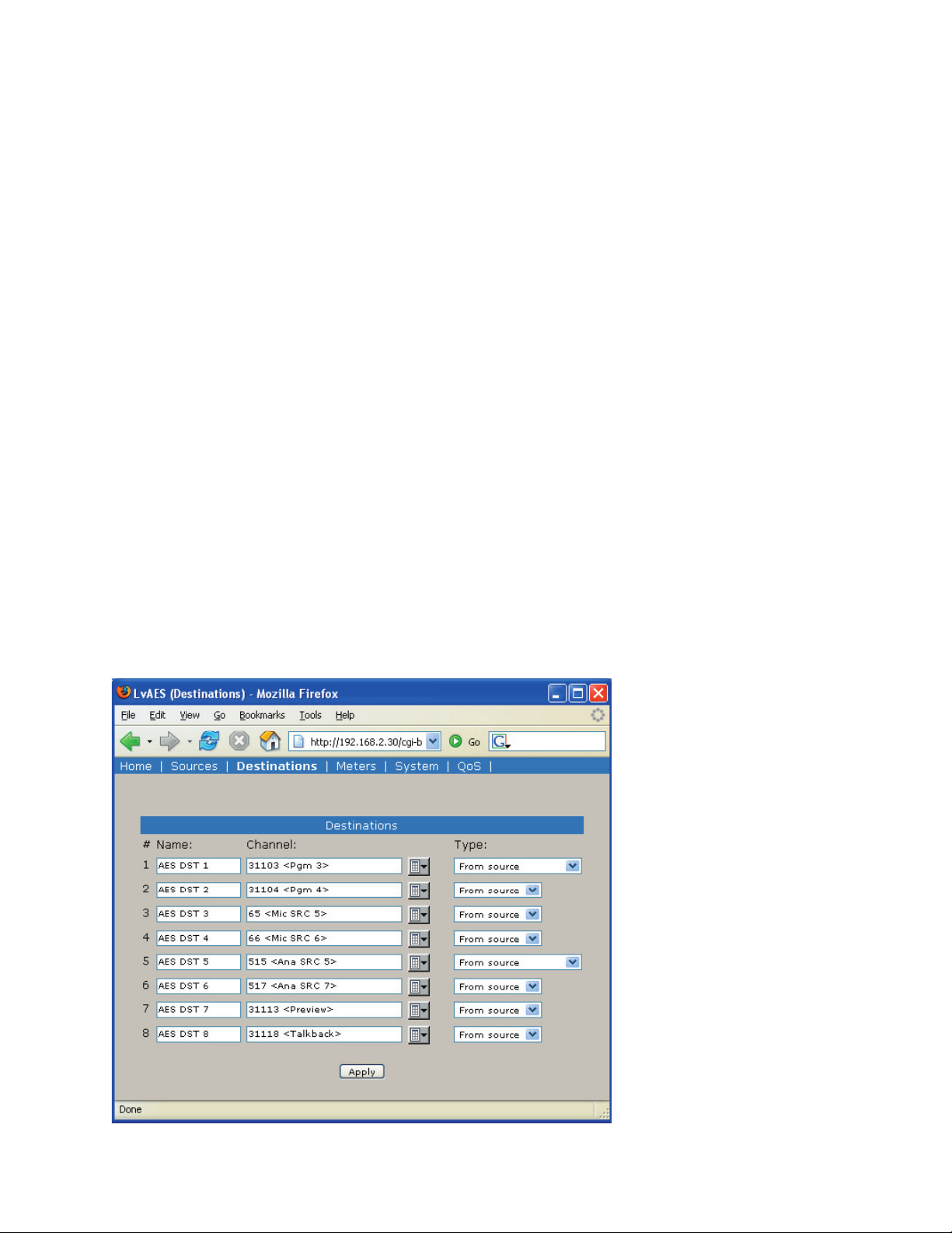
The Configure Destinations (Local Out-
puts) Page
The page permits entering information related to this
node’s local outputs. For example these can be named,
and for each you can assign a Livewire stream from the
network to be output.
These are Livewire channels to be output from each
local output. If the channel to be output is not yet avail
able on the network, you can enter the channel number
here. In the usual case you can click on the choose chan
nel button to the right of this field, and the following
Select Source screen will be displayed, see below.
You can now click on the name or channel number
of the desired source to assign it to this Destination (local output). If a Livestream (e.g. a low delay stream) is
available this will be used, otherwise a Standard Stream
will be used.
-
-
The Sources screen for the 8x8 Analog and 8x8 AES
nodes are slightly different. The Analog 8x8 Node Destinations screen is shown below:
Destination Name
This is the name used to identify this destination (lo
cal output) within the Livewire network. Destination
names are primarily used by Router software such as
Axia Pathfinder PC.
Destination Channel
Destination Type
There are four choices for this setting. Usually you
will use From Source (Livestream) for delay sensitive
audio (such as microphones or headphone feeds) or
From Source (Standard Stream) for non-delay sensitive
-
cases.
You will recall from the Introduction to Livewire;
System Design Reference & Primer manual that Livewire
permits special bi-directional streams for use with cases
where a source and destination are associated, such as a
codec or hybrid. The return feed
to such devices is usually a mixminus (clear feed) generated by a
mixer or mix engine fed back to
the device that is the primary audio source (and usually the name
of the stream in question). In ef
fect you have thus created a bi-di
rectional Livewire channel with a
single channel number.
-
-
What does this all mean in
practice? If the destination is a
codec or hybrid you’ll set the Destination Type to To Source and use
the same Channel number as the
stream representing the Codec or
Hybrids output (the caller or far
end codec audio).
3: Advanced Programming • 12
Version 2.0, February, 2007
Page 21
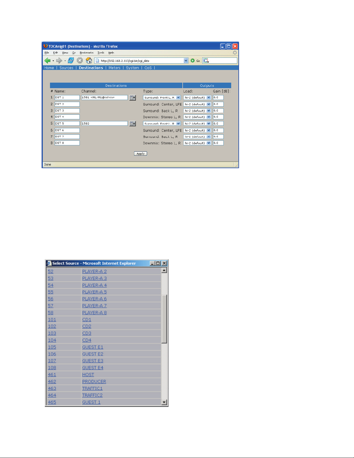
Output Load
This option is only available on the 8x8 Analog
node’s Destinations screen. This setting has two options.
The usual selection is Hi-Z and is used when the node’s
outputs are fed to High impedance destination devices.
When the node is feeding 600 Ohm inputs the 600 ohm
option should be selected. This boosts the node’s output level by ~1 dB to maintain true +4 levels into 600
Ohm equipment to ensure
unity gain. The clip point
remains at 24 dB.
Listen Links
For each destination
stream where a Standard
stream is available, the
Destinations page will
show a clickable link “Listen”. Clicking on this link
will launch the local PC
application currently registered as the default players
for “.sdp” files. For example, the Real Audio player.
NOTE: while the Apple QuickTime Player supports
.sdp files, it does not support multicast streams and will
not work.
The Meters Page
The Meters screen, shown on the below, is simply a
metering screen that shows the audio level of all local
sources (local inputs) and destinations (local outputs) for
the node. The screen is divided into two sections, with
inputs on the left and outputs on the right. Each section
has 8 pairs of meters, with a left and right meter for
each input or output. Note that the levels shown are in
the digital domain, and are therefore calibrated in dBfs.
Therefore it is worth noting that the color-coding of the
meters is somewhat arbitrary; the meters turn red 9 dB
before the clip point (e.g. 9 dB below digital full scale)
but this does not represent an overload condition.
Meters Inputs
While we recommend setting the gain setting for inputs based on the peak output clip point of the source
equipment (see Source Page, above), you can use the
meter screen to tweak input Gain settings “by eye” if
desired.
Meters Outputs
These eight pairs of meters represent the Livewire
streams being output from this node. These are primar-
Version 2.0, February, 2007
3: Advanced Programming • 13
Page 22
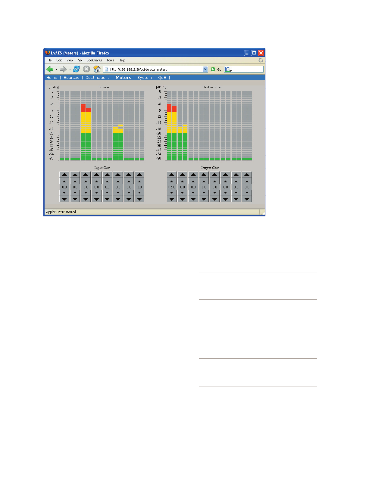
ily for confidence monitoring. As with the front panel,
the lower-most segment indicates that the designated
Livewire stream is present, even if no audio is currently
playing.
IP address. For more
detail on these see Introduction to Livewire.
Host name
An alphanumeric
name for this node.
This is used to identify
the node on the network. You may wish
to include the location
of the node (studio
and rack) in the name
for future reference.
Network address (IP
Address)
The IP address of
the local unit. Each
Livewire node must
have a unique IP address. The only ex-
ception is when two nodes are connected in the point-topoint (snake) configuration. Normally this would be set
using the front panel or using the BootP program, but it
can be checked or changed here, if needed.
NOTE: If you change this entry you will lose
The System Parameters Page
The System Parameters page, shown on the next
page, allows configuring the node’s IP address and relat
ed settings. It also permits choosing between a primary
and secondary bank of software and to download new
software into the secondary bank. The currently running
your browser connection when you click Apply,
and will need to reconnect using the new IP ad
dress.
Netmask (Subnet mask)
-
This is the IP subnet mask of the local unit. Normally
this would be set using the front panel or using the BootP
program, but it can be changed here, if needed. The typi
cal setting in most cases is 255.255.255.0 .
-
-
software version is displayed here as well. You must
click the Apply button for changes to take place.
IP Settings
These are the usual IP-related settings (see Introduction to Livewire; System Design Reference & Primer for
an overview and some good references to additional in
formation). Your network administrator should be able to
3: Advanced Programming • 14
provide the needed values. Each unit must have a unique
-
NOTE: If you change this entry you will lose
your browser connection when you click Apply,
and will need to reconnect using the new IP ad
dress.
-
Gateway (Router)
This is the IP address of the IP Router connecting
the local IP network with some other IP network. This is
needed if communication with other IP equipment that
do not share the same IP address range is required.
Version 2.0, February, 2007
Page 23
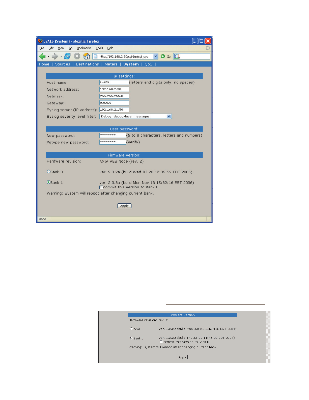
Syslog Server (IP address)
Various services generate syslog (RFC 3164) messages, which can be forwarded to a remote daemon. The
remote syslog daemon IP address can be entered on the
System WEB page.
Syslog severity level filter
You can customize logging by choosing log detail
level:
•
Emergency: system is unusable
Alert: action must be
•
taken immediately
Critical: critical condi
•
tion
Error: error conditions
•
Warning: warning con-
•
ditions
Notice: normal but sig-
•
nificant condition
-
Informational: informa-
•
tional messages
Debug: debug-level
•
message
•
Only messages with
a severity higher than
that specified by the fil
ter will be forwarded to
the remote logger.
User password
This is the password
required to connect to the
unit. It must be at least 5
characters long and may
be as long as 8 characters.
Only alphanumeric characters are permitted. To
change the password you
must enter the new and
old passwords and then
click Apply. NOTE: If you
changed the IP or Firmware settings the unit will
reboot. If you have only
entered a new password the unit will not reboot.
When logging into the node any of the following
“user names” may be used: user, USER, axia, Axia, AXIA.
The password is the same for any of the above users.
IMPORTANT! If the unit was upgraded from an
earlier version, only the user name “user” will
be active unless the Restore Defaults process
described in Section 2 has been performed
-
3: Advanced Programming • 15
Version 2.0, February, 2007
Page 24
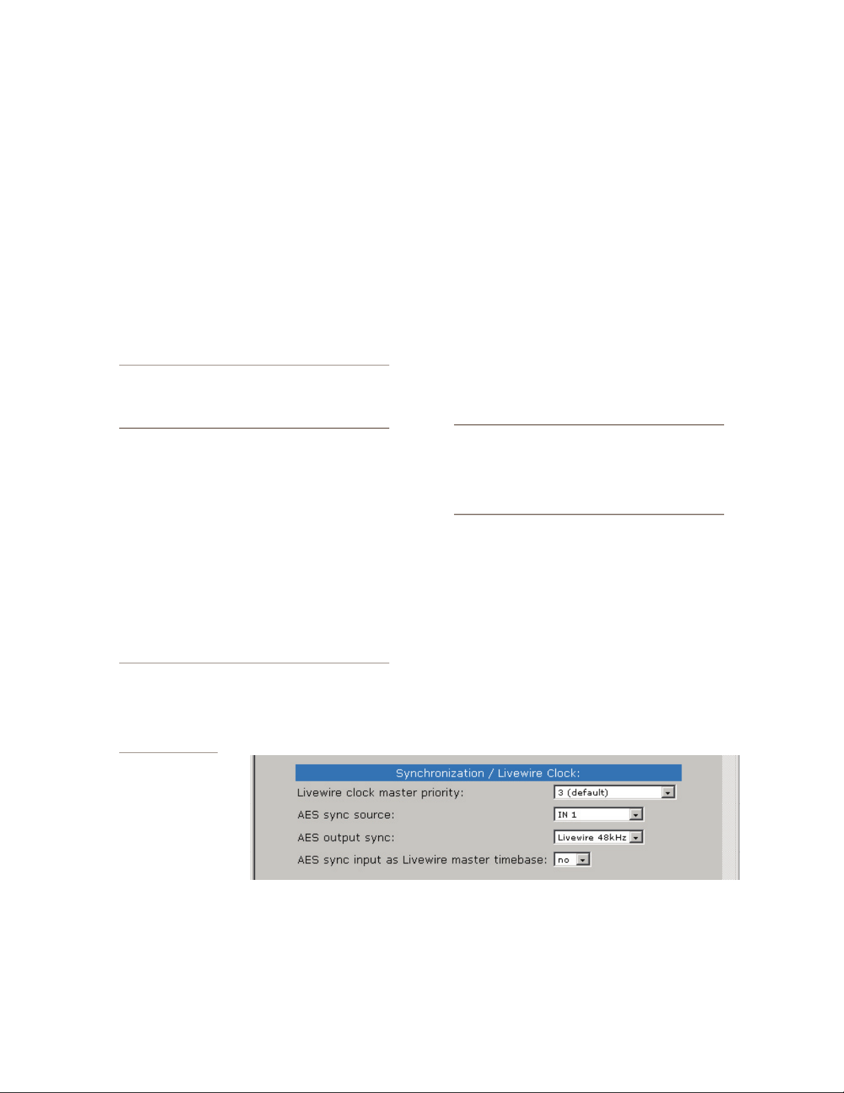
Firmware version
An Axia node has two internal memory “banks”.
Each bank contains room for a complete version of oper-
ating software. This approach allows a software update
download to be completed and checked without danger
of making the unit inoperable if the download were to be
incomplete or corrupted. It also provides and easy way
to try a new software version and still return to the old
version.
The software version in each bank is displayed here.
To change banks simply click in the “radio button” for
the desired bank and then click on Apply.
IMPORTANT! The node will reboot after you click
Apply if you change the software version. This
will result in loss of audio locally, and at any unit
using the local sources.
Saving Bank 1 Software
Software is always downloaded to bank 1 (the secondary bank). Downloading software (see below) will
overwrite the software currently in this bank, if any. If
you wish to save the software currently residing in bank
1, you can save it by moving it to bank 0 as follows:
Click on commit this version to Bank 0 box (see
1.
above).
Click on Apply. The node will now reboot.
2.
IMPORTANT! The node will reboot after you click
Apply if you change the software version. This
will result in loss of audio locally, and at any
unit using the local sources. In addition you will
reset your browser connection and will need to
reconnect.
display a prompt to permit you to choose where you
wish to locate the downloaded file. You can choose
any convenient location, just be sure to note the drive
and location where the file is to be saved.
Open a web browser and connect to the node to be
2.
updated. Enter the complete path and file name for
the software file (e.g. the file downloaded from the
Axia site), or click on the Browse button to locate the
file. Once the proper path and filename are displayed,
click on Apply to download the file.
A successful download will be indicated by the new
3.
version being displayed in the Bank 1 field. If the
download is unsuccessful the field for Bank 1 would
be blank.
4.
To run the new software click on Bank 1 and then
click on Apply to reboot the node.
IMPORTANT! The node will reboot after you click
Apply when changing between sof tware versions. This will result in loss of audio locally, and
at any unit using the local sources. In addition
you will reset your browser connection and will
need to reconnect.
The Network & QOS Page
This screen is slightly different for the Analog vs.
AES nodes. The Analog 8x8 node screen is pictured be-
low:
The settings on this screen are advanced settings, and
generally the default settings should be used. For more
on these settings see Introduction to Livewire; System
Downloading new
software
A new software version can be downloaded
into bank 1 as follows:
1.
Go to the Axia web site www.axiaaudio.com/down
loads/ and download the desired software update
for your node to your computer (this should be the
-
Design Reference & Primer. Specific application notes
or Axia support may direct you to change some of these
items in which case use the settings directed.
computer that you will use to access the node’s web
3: Advanced Programming • 16
page). Your local computer operating system should
Version 2.0, February, 2007
One setting that is commonly adjusted is Livewire
Page 25

Clock Master as described below.
Livewire Clock Master
Livewire’s clocking system (see Introduction to
Livewire for details) is automatic and largely transparent
to end users. By default the Axia hardware node with the
lowest Ethernet MAC address will be the clock “master”.
The system will automatically and transparently switch
to a new unit as clock master if need be. We do however
permit you to force clock mastership to a particular node
(not recommended) or set certain nodes as preferred for
clock mastership while maintaining automatic operation. For example you may prefer to have nodes that are
on backup power be preferred clock masters. Note that
in the automatic modes clock mastership is determined
only when the current master becomes unavailable (adding a new node will not change clock mastership regard-
less of the new node’s setting). The only exception is
the 7 (Always Master) setting. You have the following
choices for this setting:
0 (always slave) – This unit will never be used as
•
clock master.
3 (default) – The usual setting.
•
4 (Secondary Master) – Nodes with this setting will
•
be used as clock masters before those set to 3.
5 (Primary Master) – Nodes set to this setting will be
•
used as clock masters before those set to 4.
•
7 (Always Master) – This forces a particular
node to be clock master, even if another node
is currently clock master. If this mode becomes
available then the usual prioritization is used.
IMPORTANT! Only a single node on a Livewire
network should ever be set to 7 (Always Mas
ter). For this reason we do not recommend us
ing that selection.
-
-
Livewire Clock Mode
Provided for compatibility with older revisions:
•
IP low rate (default) – recommended setting
Ethernet – compatible with 1.x firmware
•
IP High rate – compatible with 2.1.x master
•
Determines the amount of buffering in the receiver.
Buffering is needed to compensate for jitter in network
packet delivery. Usually the biggest source of the jitter is
the source PC. Real-time performance varies a lot from
one system to another; some computers can provide very
low timing irregularities and allow the receive buffer to
be reduced to achieve lower audio delay. Default setting
is 100 ms.
801.1p tagging, 802.1p VLAN ID, 802.1q
Priority, & DSCP Class of Service
802.1p tagging is necessary within the Livewire net-
work to mark high-priority audio packets . This infor-
mation is used by the Ethernet switches in the packet
scheduling and queuing mechanism. It provides low-jitter packet forwarding of Livewire clock and low-latency
audio streams.
On the other hand, Standard streams don’t need tag
ging, because they are not low-latency. By default, standard streams are marked with Type of Service (DSCP
code points) information in the IP header which can be
used by L3 switches to provide better service to our audio streams than to best effort IP traffic.
There is an option to enable L2 802.1p tagging on
standard streams, and this may be used with switches
which do not use the DSCP information included in the
TOS field of the IP header. We do not enable this tagging
by default, because it wouldn’t work in cross-over Ethernet connection to PCs; most network cards do not accept
802.1p frames by default.
You should not need to change these default settings
unless you are building a system which is not based on
our recommendations.
The “VLAN ID” setting is related to the VLAN ID in
Ethernet switches. For instance, in HP switches, VLAN
starts at “0”, but in the web page, “0” is the default. So,
how do you dertermine the correct value?
-
Receive Buffer Size
VLAN ID=0 means that VLAN information is not
Version 2.0, February, 2007
3: Advanced Programming • 17
Page 26

set in 802.1p tag. The Ethernet switch, upon reception
of such frame, uses the port default VLAN ID. Only
802.1Q priority information is used.
“DSCP Class of Service” is a standard describing the
tagging of IP frames with service information. Network
equipment can be set up to provide different forwarding delay and drop precedence depending on the service
information. Our defaults are compatible with most Ethernet equipment defaults for class of service Livewire
requires; you should not need to change them unless in
structed by Axia Support.
AES Synchronization and Clock
These setting determine two factors. The Livewire
Clock Master Priority setting determines the clock mas-
tership options as described above for the Analog Node.
The AES node also permits additional synchronization
options given that it can be locked to an AES source, as
discussed below.
for this node’s AES outputs. It as two options:
Livewire 48kHz.
•
This would cause the AES outputs be synced directly to the Livewire system clock and no sample rate
conversion will be performed. However the receiv
ing unit would need to have sample rate conversion
or to be synchronous to the Livewire system clock or
dropouts due to buffer over/under run will occur.
AES Sync in
•
-
In this case, the Livewire stream will be sample rate
converted to the clock stripped of the designated
AES input. This permits operation at rates other than
48 kHz, but only if an external source at that rate is
used.
-
AES Sync Source & AES Master Timebase
If the AES sync input as Livewire master timebase
box is checked, then this node will use the AES source
fed to the input to chosen in AES sync source as the
clocking source for this node if and when it becomes
the Livewire master clock source. If this node becomes
the Livewire clock master (see above), then the entire
Livewire network will be synchronized to the AES sig-
nal fed to the selected input.
Of course Livewire clock mastership can change (as
described above) so the careful user will feed house AES
sync to multiple 8x8 AES nodes. In this case, those nodes
would all be set to priority 4 or 5 (see above) to ensure
that these nodes will be the source for the Livewire mas
ter clock whenever one of this group is available.
If AES sync source is set to Livewire 48 kHz then the
system will simply use the unit’s internal clock source if
and when it becomes clock master.
-
AES Output Sync
3: Advanced Programming • 18
This sets the output sample rate and synchronisation
Version 2.0, February, 2007
Page 27
Appendices:
1
8
+
+
R
L
Here are a few useful bits of information we think
might prove useful. Don’t forget that the manual Intro-
duction to Livewire; System Design Reference & Primer
should be your companion and has many useful tips.
cable shield) connected to the RJ-45 shield.
Unbalanced Connections
We’ve told you, both earlier in this manual, and in
Introduction to Livewire; System Design Reference &
Primer, that Axia recommends balanced audio connec-
tions when connecting analog source and destination
gear to the inputs and outputs, respectively, of Axia
nodes. Not only do we recommend this for the usual
reasons, but because inter-channel crosstalk between the
left and right channels of unbalanced signals sharing the
same Cat. 5 cable is a possibility. As we’ve mentioned
before, we recommend converting between balanced and
unbalanced at the unbalanced device and then using the
standard Cat. 5 connection from there to the Axia node.
There are a number of active balanced-to-unbalanced
and unbalanced-to-balanced adaptors commercially
available at a reasonable cost (see www.studiohub.com
for a pair of units that will easily plug and play with our
gear). We’ll suggest one more time that this approach is
the way to go, and that using unbalanced cable runs is a
good way to compromise the performance of your state
of the art Axia audio network. However, if you are in a
bind, or otherwise determined to do so, here is how we
recommend connecting Axia nodes to unbalanced equipment:
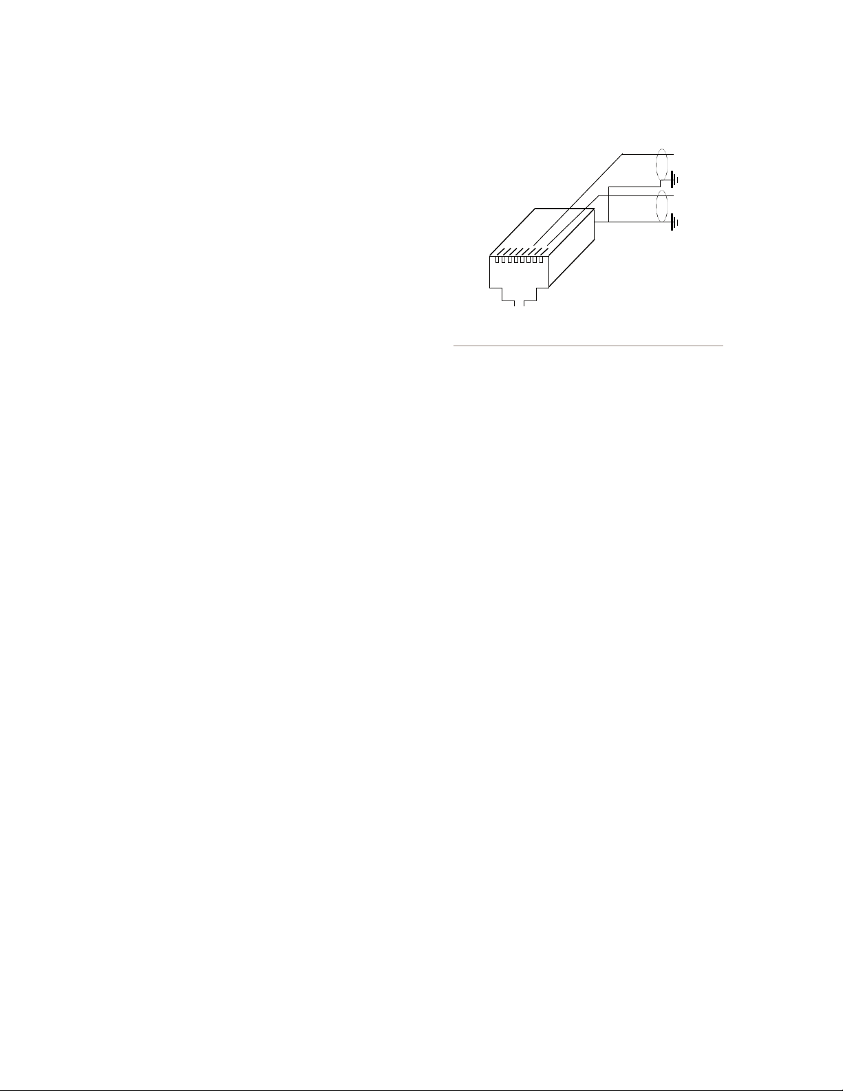
Feeding an unbalanced destination inputs from 8x8
node’s analog outputs
An external pad may be required if the destination
equipment’s inputs cannot accept signals with peak levels of +24 dBu.
Generally the unused output pin should not be tied to
the shield. Doing so will not harm the node, however do
ing so will activate a feature that will increase the output
level by 6 dB, which is generally not desirable.
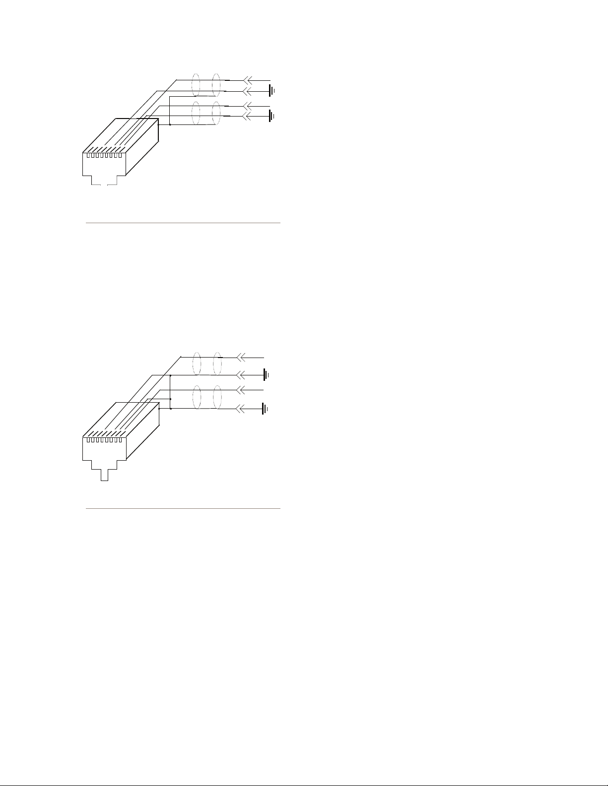
Sources
To feed an unbalanced signal from a source into the
inputs of the analog 8x8 node you must use a separate
cable for the left and right signals. We generally prefer
the method where the unbalanced signal is presented
across the differential balanced inputs of the node. The
handling of the shield will depend on the equipment and
grounding practices used.
If both pieces of equipment are grounded to a facility
grounding system then the shield may be left open at one
end (or both ends), as follows.
-
Unbalanced Destinations
To feed audio to an unbalanced destination from the
8x8 Analog node you must use a separate cable for the
left and right signals, and you will need a shielded RJ-45
plug so you can terminate the shield of the audio cables.
Pin 1 will feed the Left signal with the signal common
(e.g. cable shield) connected to the RJ-45 shield. Pin 3
will feed the Right signal with the signal common (e.g.
Version 2.0, February, 2007
Appendices • 19
Page 28
1
8
+
+
R
L
Axia node’s analog inputs fed fr om an unbalanced
1
8
+
+
R
L
source where both pieces of equipment are tied to a
facility ground.
Alternatively, if both pieces of equipment are not
both tied to a common facility ground, both sides of the
shield must be connected. In this case the “-“ side of the
nodes inputs are tied to the shield of the RJ-45 plug as
follows:
STL Slave and STL Snake modes on Clock Master
Priority options
IP Low Rate is now set as the default receive Clock
mode in the LW Clock Mode options field. (Note that
this setting only defines the RECEIVE type of stream.
It does not change the clock stream type when the
node is acting as the Master Clock. We recommend
that you do not change this setting.)
A Standard Stream Buffering option, which is set to
100ms as default. (Note that this setting should not
be adjusted unless advised otherwise by Axia Tech-
nical Support.)
A “Master/Sync” confidence tally is added to the
Router Selector Node display.
Using Axia Audio Nodes as snakes or STLs
Note that the setup options described below require
that Node Software v2.3.2a or higher must be in-
stalled to work correctly.
OPTION 1 - Using two nodes back to back without
an Ethernet switch
In this scenario, the clock sync mode will set the
Clock Rate to a Low Rate sync packet regardless
Axia node’s inputs fed from a floating source, with no
facility ground in common with the Axia node.
of the Livewire Clock Mode setting. This enables a
more stable SYNC mode, eliminating the need for an
Ethernet switch between the nodes handling QOS of
the clock sync signal.
Using Axia Nodes with Ethernet
Radios
Navigate to the “QOS” web pages of the Audio
Nodes you’ll be using. Determine which one will be
the master and which the slave, and set the new “STL
Applies to Node Software v2.3.2a and higher
Snake” and “STL Slave” clock priority modes to the
appropriate values.
There are several changes and additions to Axia Audio Nodes software beginning with v2.3.2a designed
to simplify the operation of STLs and audio snakes
using Axia nodes in conjunction with Ethernet Ra
dios.
Appendices • 20
These additions include:
-
Typically, you will set the Clock Master Priority op-
tion on the Node located in the studio to “7 (Always
Master) STL Snake”. The Node on the remote end of
the link should be set to “0 - (Always Slave) STL”.
All stream types must be set to Standard streams.
Version 2.0, February, 2007
Page 29

Leave Standard Stream buffering at 100ms (the default setting).
OPTION 2 - Connecting a “remote” Audio Node to
an existing Axia network using Ethernet Radio
If you are using Studio Engines and/or existing
nodes connected to an Ethernet switch, then these
instructions assume that you have a current Livewire
Network and are adding a node at a remote location
connected via an IP radio. You must maintain the
high rate Master clock sync packets for these devices
in order for all nodes to sync properly. This is especially important for the well-being of the Axia Studio
Mix Engines.
In this case, you will need to have at least ONE Audio Node on the main Livewire network designated
as the MASTER CLOCK and running version 2.3.2a
software. It should be set to a higher priority than
all other nodes running earlier software versions. We
recommend choosing “7 - (Always Master)”. Do not
select “7 – (Always Master) STL Snake” for this application.
number of Ethernet radios on the market, we are un
able to make specific recommendations on which ra-
dio to choose, or their exact optimal settings.
Some Quality of Service options may assist or hin-
der the operation of the radio for multicast UPD data
packets. This may involve turning ON or OFF some
or all the “smarts” within the radio. User experience
will differ from model to model. We suggest that you
contact your radio’s manufacturer for additional sup-
port on the operation of the radios in this mode. For
the purposes of passing Livewire streams reliably,
we desire that the IP radios behave as much as pos-
sible like a simple piece of CAT6 cable, with mini-
mal latency.
Questions on the operation of the Axia Audio Nodes
can be emailed to Axia support at support@axiaaudio.
com.
-
The remote node at the receive end of the Ethernet radio should likewise be running v2.3.2a software. Its
clock setting should be “0 - (Always Slave) STL”.
Deep Tech: A node running version 2.2.0, when operating as the current Clock Master, will generate
two clock streams: a High rate and a Low rate clock
sync. Nodes running version 2.1.x and earlier do not
have this dual clock feature and require the High rate
sync to operate as well.
Streams sent to the “remote” node should all be
STANDARD streams. Leave Standard Stream buffering at 100ms (the default setting) on the receiving
node.
IP Radio Settings and Recommendations:
Settings on your Ethernet radios will have to be
tweaked as needed. Unfortunately, due to the large
Appendices • 21
Version 2.0, February, 2007
Page 30

Appendices • 22
Version 2.0, February, 2007
Page 31

Specifications and Warranty
Axia System Specifications
Microphone Preamplifiers
Source Impedance: 150 ohms
•
Input Impedance: 4 k ohms minimum, balanced
•
•
Nominal Level Range: Adjustable, -75 dBu to -20 dBu
Input Headroom: >20 dB above nominal input
•
Output Level: +4 dBu, nominal
•
Analog Line Inputs
Input Impedance: >40 k ohms, balanced
•
Nominal Level Range: Selectable, +4 dBu or -10dBv
•
Input Headroom: 20 dB above nominal input
•
Analog Line Outputs
Output Source Impedance: <50 ohms balanced
•
Output Load Impedance: 600 ohms, minimum
•
Nominal Output Level: +4 dBu
•
Maximum Output Level: +24 dBu
•
Digital Audio Inputs and Outputs
Reference Level: +4 dBu (-20 dB FSD)
•
Impedance: 110 Ohm, balanced (XLR)
•
Signal Format: AES-3 (AES/EBU)
•
AES-3 Input Compliance: 24-bit with selectable sample rate conversion, 32 kHz to 96kHz input sample rate
•
capable.
AES-3 Output Compliance: 24-bit
•
Digital Reference: Internal (network timebase) or external reference 48 kHz, +/- 2 ppm
•
Internal Sampling Rate: 48 kHz
•
Output Sample Rate: 44.1 kHz or 48 kHz
•
A/D Conversions: 24-bit, Delta-Sigma, 256x oversampling
•
•
D/A Conversions: 24-bit, Delta-Sigma, 256x oversampling
Latency <3 ms, mic in to monitor out, including network and processor loop
•
Frequency Response
Any input to any output: +0.5 / -0.5 dB, 20 Hz to 20 kHz
•
Dynamic Range
Analog Input to Analog Output: 102 dB referenced to 0 dBFS, 105 dB “A” weighted to 0 dBFS
•
Analog Input to Digital Output: 105 dB referenced to 0 dBFS
•
•
Digital Input to Analog Output: 103 dB referenced to 0 dBFS, 106 dB “A” weighted
Specifi cations & Warranty • 23
Version 2.0, February, 2007
Page 32

Digital Input to Digital Output: 138 dB
•
Equivalent Input Noise
Microphone Preamp: -128 dBu, 150 ohm source, reference -50 dBu input level
•
Total Harmonic Distortion + Noise
Mic Pre Input to Analog Line Output: <0.005%, 1 kHz, -38 dBu input, +18 dBu output
•
Analog Input to Analog Output: <0.008%, 1 kHz, +18 dBu input, +18 dBu output
•
Digital Input to Digital Output: <0.0003%, 1 kHz, -20 dBFS
•
•
Digital Input to Analog Output: <0.005%, 1 kHz, -6 dBFS input, +18 dBu output
Crosstalk Isolation and Stereo Separation and CMRR
Analog Line channel to channel isolation: 90 dB isolation minimum, 20 Hz to 20 kHz
•
Microphone channel to channel isolation: 80 dB isolation minimum, 20 Hz to 20 kHz
•
Analog Line Stereo separation: 85 dB isolation minimum, 20Hz to 20 kHz
•
Analog Line Input CMRR: >60 dB, 20 Hz to 20 kHz
•
Microphone Input CMRR: >55 dB, 20 Hz to 20 kHz
•
Power Supply AC Input
Auto-sensing supply, 90VAC to 240VAC, 50 Hz to 60 Hz, IEC receptacle, internal fuse
•
•
Power consumption: 35 Watts
Operating Temperatures
-10 degree C to +50 degree C, <90% humidity, no condensation
•
Dimensions and Weight
Microphone node: 1.75 inches x 17 inches x 10 inches, 6 pounds
•
Analog Line node: 1.75 inches x 17 inches x 10 inches, 6 pounds
•
AES/EBU node: 1.75 inches x 17 inches x 10 inches, 6 pounds
•
Router Selector node: 1.75 inches x 17 inches x 10 inches, 6 pounds
•
GPIO node: 1.75 inches x 17 inches x 13 inches, 8 pounds
•
Studio Mix Engine 3.5 inches x 17 inches x 15 inches, 10 pounds
•
Specifi cations & Warranty • 24
Version 2.0, February, 2007
Page 33

Axia Node Limited Warranty
This Warranty covers “the Products,” which are defined as the various audio equipment, parts, software and acces-
sories manufactured, sold and/or distributed by TLS Corp., d/b/a Axia Audio (hereinafter “Axia Audio”).
With the exception of software-only items, the Products are warranted to be free from defects in material and work-
manship for a period of one year from the date of receipt by the end-user. Software-only items are warranted to be free
from defects in material and workmanship for a period of 90 days from the date of receipt by the end-user.
This warranty is void if the Product is subject to Acts of God, including (without limitation) lightning; improper
installation or misuse, including (without limitation) the failure to use telephone and power line surge protection devices; accident; neglect or damage.
EXCEPT FOR THE ABOVE-STATED WARRANTY, AXIA AUDIO MAKES NO WARRANTIES, EXPRESS
OR IMPLIED (INCLUDING IMPLIED WARRANTIES OF MERCHANTABILITY AND FITNESS FOR A PARTICULAR PURPOSE).
In no event will Axia Audio, its employees, agents or authorized dealers be liable for incidental or consequential
damages, or for loss, damage, or expense directly or indirectly arising from the use of any Product or the inability to
use any Product either separately or in combination with other equipment or materials, or from any other cause.
In order to invoke this Warranty, notice of a warranty claim must be received by Axia Audio within the above-
stated warranty period and warranty coverage must be authorized by Axia Audio. If Axia Audio authorizes the performance of warranty service, the defective Product must be delivered, shipping prepaid, to: Axia Audio, 2101 Superior
Avenue, Cleveland, Ohio 44114.
Axia Audio at its option will either repair or replace the Product and such action shall be the full extent of Axia
Audio’s obligation under this Warranty. After the Product is repaired or replaced, Axia Audio will return it to the party
that sent the Product and Axia Audio will pay for the cost of shipping.
Axia Audio’s authorized dealers are not authorized to assume for Axia Audio any additional obligations or liabili-
ties in connection with the dealers’ sale of the Products.
Axia Audio’s products are to be used with registered protective interface devices which satisfy regulatory require
ments in their country of use.
rev 12/08/04 v 1.0 RKT
rev 12/28/04 v 1.0b RKT
rev 01-07-05 v1.0c RKT
Part # 1490-00038-001
-
Specifi cations & Warranty • 25
Version 2.0, February, 2007
Page 34

Page 35

Axia Audio, a Telos Company • 2101 Superior Ave. • Cleveland, Ohio, 44114, USA • +1.216.241.7225 • www.Axia Audio.com
 Loading...