

Page 1

STS 6030 INSTRUCTION, OPERATION,
AND MAINTENANCE MANUAL
Enclosed Programmable Automated
Fuel Maintenance Systems
1.239.690.9859
1.877.425.4239 Toll Free
www.AXI-International.com
AXI.International AXInternational AXIFuel AXIFuel
REV03016030010218
Page 2
STS 6030
AFC 705/710 Fuel Catalyst
Stainless Steel Enclosure
Automatic Water Drain
Cabinet Color Options
Stand
Stainless Steal Plumbing
STS 6030 OPTIONS:
REPLACEMENT FILTER OPTIONS:
STS SYSTEM INTEGRATION:
Smart Filtration Controller
AXI Inline LG-X 4000 Conditioner
Primary Final Filter
Enclosure Heater (Optional)
Secondary Final Filter
Fuel Outlet (Discharge)
Outlet Ball Valve
Flow Switch with Sight Glass
Drain Valves
Leak Detector
Pressure Switch
Gear Pump
Wye-Strainer
Fuel Inlet (From Tank)
Vacuum Switch
1.
2.
3.
4.
5.
6.
7.
8.
9.
10.
11.
12.
13.
14.
15.
Pre Filter
1µ Micro Filter Element
5µ Micro Filter Element
10µ Micro Filter Element
FBO-60339
FBO-60340
FBO-60357
25µ Micro Filter Element
FBO-60341
Part No.
Fine Filter
1µ Coalescing Filter Element
5µ Coalescing Filter Element
10µ Coalescing Filter Element
FBO-60336
FBO-60337
FBO-60356
25µ Coalescing Filter Element
FBO-60338
Part No.
STS 6030
Enclosed Automated Fuel Maintenance Systems
1.239.690.9589
AXI.International AXInternational AXIFuel AXIFuel
1.877.425.4239 Toll Free
www.AXI-International.com
15
1
6
7
9
13
14
2 3 54
8
101112
DIRTY FUEL
CLEAN FUEL
UNUSED HOT FUEL
ENGINE
PUMP SET
CLEAN FUEL
REV02016030011217
Enclosed Automated Fuel Maintenance Systems
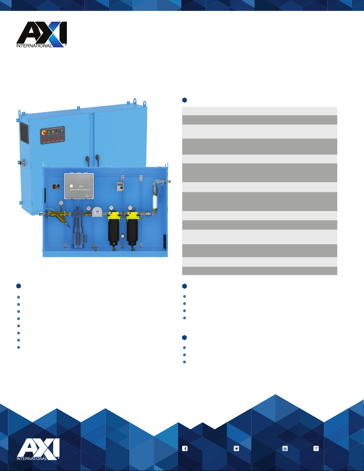
The STS 6030 Programmable Automated Fuel Maintenance System is designed to optimize and maintain diesel fuel
indefinitely. Adding an STS 6030 system will remove particulate, separate water, and condition stored fuel. This innovative
process stabilizes diesel and bio-fuels, eliminates microbial contamination, and ensures clean reliable fuel at all times.
Generators and pumps operating in remote locations are ideal applications for STS 6030 systems.
STS 6000 SERIES SAFETY FEATURES:
Automatic Alerts
Pump Shut Down When Filters Need Service
Leak Detection
Water Detection
High Filter Vacuum
High Pump Pressure
Low Fuel Flow Alert
Emergency Stop
STS 6030 SPECIFICATIONS
Flow Rate (@60Hz) 30 GPM/1800 GPH (113.6 LPM/6814 LPH)
Y-Strainer 20 Mesh
Primary Filter
Secondary Filter 10μ Racor FBO Coalescer
Fuel Conditioner LG-X 4000 Inline Conditioner
System Controller
Pump 2 HP Gear Pump
Power 208-230V/1Ph/60Hz/20A or
Plumbing Carbon Steel
Ports 2” NPT In 1-1/2” NPT Out
Enclosure Cabinet NEMA 12 (IP55), 13 (IP65), 4 (IP66), and
Dimensions 56” x 72” x 17” (H x W x D)
Weight ≈ 760 lbs (344.7 kg)
Not for use with fluids that have a flash point below 100°F (37.8°C).
1, 5, 10 or 25μ Racor FBO Particulate
or 1, 5, 10 or 25μ Racor FBO Water Block
or 1, 5, 10 or 25μ Racor FBO Water Block
Programmable, Fully Automated UL 508A
SMART Filtration Controller with BMS/BAS
Interface and Digital Text Readout
230V/1Ph/50Hz/15A or
480V/1Ph/60Hz/15A
4X (IP66) Powder Coat or Stainless Steel
(142 x 183 x 43 cm)
SMART FILTRATION CONTROLLERS:
Maintenance Alert Log File
Runtime Totalizer
Alarm History
On-Screen Help
ALL STS SYSTEMS FEATURE:
Multi-stage Water Removal and Particulate Filtration
NEMA 12,13, 4, 4X Powder Coated or Stainless Enclosure
UL508A Smart Filtration Controller
1.239.690.9589
1.877.425.4239 Toll Free
www.AXI-International.com
AXI.International AXInternational AXIFuel AXIFuel
REV02016030011217
Page 3
STS 6030
Enclosed Automated Fuel Maintenance Systems
15
14
13
1
2 3 54
101112
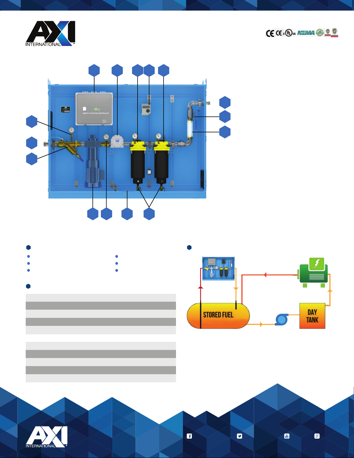
Smart Filtration Controller
1.
AXI Inline LG-X 4000 Conditioner
6
7
8
2.
Primary Final Filter
3.
Enclosure Heater (Optional)
4.
Secondary Final Filter
5.
Fuel Outlet (Discharge)
6.
Outlet Ball Valve
7.
Flow Switch with Sight Glass
8.
Drain Valves
9.
Leak Detector
10.
Pressure Switch
11.
Gear Pump
12.
Wye-Strainer
13.
Fuel Inlet (From Tank)
14.
Vacuum Switch
15.
9
STS 6030 OPTIONS:
AFC 705/710 Fuel Catalyst
Stainless Steel Enclosure
Automatic Water Drain
Cabinet Color Options
Stand
Stainless Steal Plumbing
REPLACEMENT FILTER OPTIONS:
Pre Filter
1µ Micro Filter Element
5µ Micro Filter Element
10µ Micro Filter Element
25µ Micro Filter Element
Fine Filter
1µ Coalescing Filter Element
5µ Coalescing Filter Element
10µ Coalescing Filter Element
25µ Coalescing Filter Element
Part No.
FBO-60339
FBO-60340
FBO-60357
FBO-60341
Part No.
FBO-60336
FBO-60337
FBO-60356
FBO-60338
STS SYSTEM INTEGRATION:
UNUSED HOT FUEL
DIRTY FUEL
CLEAN FUEL
PUMP SET
ENGINE
CLEAN FUEL
1.239.690.9589
1.877.425.4239 Toll Free
www.AXI-International.com
AXI.International AXInternational AXIFuel AXIFuel
REV02016030011217
Page 4

Table of Contents
General Overview ...............................................................................................................................................................
System Components .........................................................................................................................................................
Control and Safety Devices ..........................................................................................................................................
Pump/Motor .................................................................................................................................................................
Pre-Filter/Water Separator ..........................................................................................................................................
Final Filter(s) ..................................................................................................................................................................
Fuel Conditioner ............................................................................................................................................................
Filter Drain .....................................................................................................................................................................
System Enclosure .........................................................................................................................................................
Plumbing ........................................................................................................................................................................
System Operation ..............................................................................................................................................................
Pump Operation ............................................................................................................................................................
Emergency Stop ............................................................................................................................................................
Alarms .............................................................................................................................................................................
Primary Inspection .............................................................................................................................................................
Checklist .........................................................................................................................................................................
Installation ...........................................................................................................................................................................
Mounting ........................................................................................................................................................................
Electrical .........................................................................................................................................................................
Plumbing ........................................................................................................................................................................
Typical System Installation Conguration Schematic .................................................................................................
Installation Precautions .................................................................................................................................................
Controller .............................................................................................................................................................................
Setting Date and Time ...................................................................................................................................................
Programming the Timer .................................................................................................................................................
Menu Structure ..............................................................................................................................................................
Priming the System ............................................................................................................................................................
Priming Procedure .........................................................................................................................................................
Commissioning/Initial Startup ........................................................................................................................................
Flow Switch Setting & Adjustment ................................................................................................................................
Gauge Venting & Accuracy ...........................................................................................................................................
Initial Test Procedures ...................................................................................................................................................
Maintenance ........................................................................................................................................................................
Preventative Maintenance ............................................................................................................................................
Servicing Pre-Filter/Water Separator ..........................................................................................................................
Servicing Final Filter(s) ..................................................................................................................................................
Troubleshooting .............................................................................................................................................................
Filter Chart ......................................................................................................................................................................
Warranty ...............................................................................................................................................................................
Parts/Service ......................................................................................................................................................................
5
6
6
6
6
6
6
6
7
7
8
8
8
9
12
12
13
13
13
14
14
15
16
16
16
16
17
17
18
18
18
18
17
17
18
19
20
21
22
23
REV03016030010218
Page 5

General Overview
STS 6030 Specications
Flow Rate ................................................................................
Outline Dimensions (Enclosure) ............................................
System Weight .......................................................................
Operating Temperature ..........................................................
Electrical .................................................................................
Pump .......................................................................................
Suction Capability (Primed) ...................................................
Motor .......................................................................................
Timer .......................................................................................
Inlet ..........................................................................................
Outlet .......................................................................................
Maximum Fluid Viscosity ........................................................
30 GPM/1800 GPH (113.6 LPM/6814 LPH)
14,400 gallons (54,510 liters) per 8 hour shift
43,200 gallons (163,530 liters) per 24 hours
56” x 72” x 17” (142 x 183 x 43 cm) (H x W x D)
≈ 760 lbs (344.7 kg)
41 - 104°F (5 - 40°C)
208-230V//1Ph60Hz/20A, 120V/1Ph/60Hz/15A,
or 230V/1Ph/50Hz/15A
Gear pump
15 ft (4.57 m) suction (vertical lift) or 100’ (30.48 m) horizontal
run (lines > 1-1/2”, primed)
2 HP single phase, continuous duty, thermally protected
Programmable digital timer
2” NPT male port
1-1/2” NPT male port
5 cSt
OVERVIEW
OVERVIEWSYSTEM COMPONENTSPRIMARY INSPECTIONINSTALLATION OPERATIONPRIMING CONTROLLERCOMMISSIONINGMAINTENANCE
Note: The system is designed to meet environmental standards for safe operation. (Not for use with uids that have a
ash point below 100°F (37.8°C), e.g. gasoline, alcohol, etc.)
REV03016030010218
5
Page 6

System Components
OVERVIEW
SYSTEM COMPONENTSPRIMARY INSPECTIONINSTALLATION OPERATIONPRIMING CONTROLLERCOMMISSIONINGMAINTENANCE
SYSTEM COMPONENTS
Control and Safety Devices
• AXI International “Smart Filtration Controller” in electrical sub enclosure is a modular – UL 508A listed Industrial Control
• Programmable Digital Timer – Memory backup to retain program memory during power outages
• Pump control switch (Auto/Off/Manual), weatherproof, key operated
• Alarm Reset - weatherproof push button
• Power available indicator
• Pump running indicator
• External remote shutdown feature
• Inlet and outlet shut off ball valves
• Emergency stop button (outside enclosure)
• Leak sensor and alarm indicator (system shutdown)
• High vacuum alarm indicator and system shutdown (vacuum sensor)
• Secondary lter high pressure alarm indicator and system shutdown (pressure sensor)
• High water alarm indicator and system shutdown (water sensor)
• Pump motor starter with single-pole circuit breaker and contact
Pump/Motor
• Positive displacement gear pump
• Motor – UL listed with thermal overload protection
• Service Factor (1.00)
Panel
Strainer
• Wye-Strainer with drain valve
Final Filter(s)
• Dual, parallel RACOR FBO ne lters, down to 1µ nominal, 5µ nominal, and 5µ coalescing lter cartridges (other
cartridges available)
• Drain valve on the bottom
• Differential pressure gauges
Fuel Conditioner
• Inline Magnetic Fuel Conditioner eliminates and prevents the formation of sediments that naturally occur in diesel fuel
and bio-blends
Carbon Steel Plumbing
6
REV03016030010218
Page 7

System Enclosure
• 14-gauge steel construction with continuously welded seams
• Concealed hinges
• Finished in polyester powder coat inside and out over phosphatized surfaces
• Spill basin with leak detection
• Louvered side panels
• Brackets for wall mounting
• Literature pocket
OVERVIEW
Remote Monitoring Module (Option)
• System status and alarm monitored from remote location
Enclosure Heater (Option)
• Ensures electronics stay within operational temperature range
• Prevents internal holding tanks from freezing or gelling
• Built-in thermostat, eld adjustable to required temperature
SYSTEM COMPONENTSPRIMARY INSPECTIONINSTALLATION OPERATIONPRIMING CONTROLLERCOMMISSIONINGMAINTENANCE
SYSTEM COMPONENTS
REV03016030010218
7
Page 8

OVERVIEW
Pump Operation
Apply control power to unit. Place breakers for the Smart Filtration Controller in the “ON” position.
Automatic:
SYSTEM COMPONENTSPRIMARY INSPECTIONINSTALLATION OPERATIONPRIMING CONTROLLERCOMMISSIONINGMAINTENANCE
Place the key switch in the “AUTO” position. When the timer contacts close, the pump will start and run until the timer setting
has expired. See the Controller section for setting run times.
System Operation
!WARNING! This system is not meant for use with gasoline or any other ammable liquids having a ash
point less than 100°F (37.8° C). Use with gasoline or any ammable liquids at a temperature exceeding their
ash point presents an immediate explosion and re hazard.
OPERATION
Manual (Override):
Place the key switch in the “MANUAL” position. The pump motor will run until the switch is returned to the “OFF” or “AUTO”
mode positions, or until an alarm or overload has been tripped.
8
REV03016030010218
Page 9

Alarms
The system is equipped with an AXI International Smart Filtration Controller. System and alarm status are displayed on the
industrial control panel (on the door) via indicator lights, and on the text box on the electronic controller.
Alarms featured on the system include:
• Leak Detection
• Low fuel ow alarm indicator
• High vacuum alarm indicator and system shutdown (vacuum sensor)
• Secondary lter high pressure alarm indicator and system shutdown (pressure sensor)
• High water alarm indicator and system shutdown (water sensor)
• Secondary lters alarm indicator and system shutdown (differential pressure transmitters)
Once triggered alarms are addressed, each alarm can be reset by pressing the weatherproof “ALARM RESET” push button
located on the outside of the enclosure door.
Emergency Stop
Note: In case of an emergency, the pump can be turned off and disabled by pressing the red “EMERGENCY STOP” button
on the outside of the enclosure door.
OVERVIEW
SYSTEM COMPONENTSPRIMARY INSPECTIONINSTALLATION OPERATIONPRIMING CONTROLLERCOMMISSIONINGMAINTENANCE
OPERATION
To release “EMERGENCY STOP” button, turn the red knob in the direction indicated by the arrows on the mushroom button
and push the “ALARM RESET” button to reset.
Enclosure Heater (Option)
The Enclosure Heater is an option used to maintain a certain temperature within the system enclosure and ensure that
components in contact with water do not freeze. It also ensures that electronics stay within their operating range. The
Enclosure Heater comes with a built-in thermostat, and can run continuously in cold environments.
REV03016030010218
9
Page 10

Upon arrival, the system and accessories must be visually inspected before installation. Improper handling during shipping
OVERVIEW
may cause physical or electrical problems. Immediately report or note any damages (also concealed ones) to the shipper.
Checklist
❑ If the packing crate shows signs of damage, inspect the enclosure for damage.
❑ Check the entire outside of the enclosure for damage that could indicate internal mechanical or electrical problems.
❑ Check locking handles, door and hinge operation.
SYSTEM COMPONENTSPRIMARY INSPECTIONINSTALLATION OPERATIONPRIMING CONTROLLERCOMMISSIONINGMAINTENANCE
❑ Check pump/motor hardware and all plumbing connections for tightness.
❑ Check all electrical terminals and connections for tightness.
Primary Inspection
PRIMARY INSPECTION
10
REV03016030010218
Page 11

Installation
!IMPORTANT! It is recommended that only qualied, experienced personnel, familiar with this type of
equipment, who have read and understood all the instructions in this manual should install, operate, and
maintain the system.
Mounting
The unit is a totally enclosed system, and should be permanently wall mounted on a hard, level surface. Use provided
mounting feet for proper fastening. This weatherproof unit is designed for well-ventilated indoor or outdoor use within
specied temperature range, and should be located as close to the tank as possible. Please allow about 1’ (30.5 cm) of
space between the side louvers of the enclosure and nearby objects. This space is necessary to ensure sufcient ventilation
of cooling air for the system and motor.
Electrical
!WARNING! To avoid the risk of electric shock, make sure that the power supply to the system is
disconnected, and ensure that the system is at zero volts, before working on any of the system’s electrical
parts.
OVERVIEW
SYSTEM COMPONENTSPRIMARY INSPECTIONINSTALLATION OPERATIONPRIMING CONTROLLERCOMMISSIONINGMAINTENANCE
Make sure that the system’s power requirements and rated voltage/frequency match the electrical system (see wiring
diagram). The system may only be connected to properly grounded power sources for operator safety. Connect all
components to the ground studs provided as shown on the electrical drawings.
!WARNING! The whole system (enclosure, doors, plumbing, motor, electric sub panel) must be properly
grounded for operator safety.
Depending on length of run, use copper wiring according to specication in wiring diagram and connect system to a separate
UL listed breaker (not included) appropriate for branch circuit protection.
Note: Wiring and electrical installation must be in accordance with all applicable federal, state, and local rules, laws,
standards, and regulations.
Remote Pump Shutdown Feature:
If required, connect the “external pump shut down input terminal” (see wiring diagram) per specication on electric diagram
to disable pump (e.g. remote shut down, remote pump control). Please note that the contact needs to be supplied with +24V
DC from the power supply of the Smart Filtration Controller.
INSTALLATION
Remote Monitoring - Dry Contacts:
The Smart Filtration Controller provides two Normally Open (N.O.) dry contacts for remote alarm monitoring. Please see
wiring diagram for contact rating, connection, and location.
1. “Summary Alarm” – dry alarm contact for high vacuum, high pressure, no ow, or water detection (as well as emergency
stop and overload relay triggered)
2. “Leak Detection” – dry alarm contact for leak detection
REV03016030010218
11
Page 12
Plumbing
Use proper quality approved fuel line materials with at least 2” (5.1 cm) inner diameter on the suction side from the tank and
at least 1-1/2” (3.8 cm) inner diameter on the return/discharge side back to the tank. For long suction side plumbing runs, it
OVERVIEW
SYSTEM COMPONENTSPRIMARY INSPECTIONINSTALLATION OPERATIONPRIMING CONTROLLERCOMMISSIONINGMAINTENANCE
is recommended to install oversized pipe, or 2” in diameter.
Note: Do not put any stress on plumbing of the system, and use a backing wrench when connecting the external plumbing.
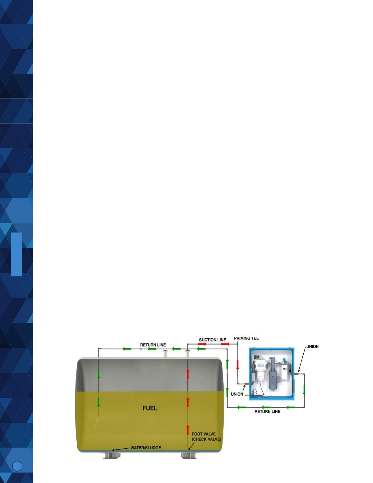
The pick up tube/line(s) should originate from the lowest point of the tank to ensure all water is removed, connected directly
to the system’s “PUMP INLET – SUPPLY FROM TANK” port, located on the left hand side of the enclosure, and kept as
short as possible. It is recommended to install an oversized, low restriction foot valve to keep the system primed, especially
if the “PUMP INLET – SUPPLY FROM TANK” port of the system is located above the lowest possible fuel level in the tank.
A priming tee should be installed on the highest point of the suction line to be able to easily prime the lines and system.
The return line(s) should be plumbed to the “PUMP OUTLET – RETURN TO TANK” port (on the right side of the system)
and enter the tank as far as possible from the pick up tube, close to the tank bottom. A (swing) check valve may be required
on the return line(s) for some installations to prevent back ow pressure.
Multiple suction and/or return lines may be connected to a manifold outside the system.
INSTALLATION
Note: Anti-Siphon or other external plumbing devices may be required – please check local regulations/code.
The system capabilities are 15’ (4.57 m) suction (vertical) or 100’ (30.48 m) horizontal, when connected to piping of 1-1/2”
ID, or more, with no additional ow restrictions, such as valves, 90-degree connectors, or other plumbing accessories. For
continuous optimal performance, make sure suction and discharge lines are free and that nothing is blocking the ow of fuel,
and that the suction line always stays primed.
Note: Plumbing installation must be in accordance with all applicable federal, state, and local rules, laws, standards, and
regulations.
Typical Plumbing/Above Ground Tank Installation (Schematically)
12
REV03016030010218
Page 13

Important Installation Precautions
The suction line of the system should be independent and separate from the suction line of the engine. If that is not possible,
appropriate valves must be installed to completely separate the system from the engine fuel system to prevent any possible
interference with safe engine operation.
It is highly recommended to plumb the discharge line independent and separate of the engine’s fuel return line back to the
tank. If the return line from the engine and the discharge of the system must be combined in any way, adequate valves
should be installed to prevent any possible interference with safe engine operation.
OVERVIEW
Note: If any of the system’s fuel lines are used in combination with the engine’s fuel system, the system should be disabled
during engine operation (use the provided “Remote Pump Shut Down” feature as shown in the electrical drawing and
described above).
SYSTEM COMPONENTSPRIMARY INSPECTIONINSTALLATION OPERATIONPRIMING CONTROLLERCOMMISSIONINGMAINTENANCE
INSTALLATION
REV03016030010218
13
Page 14

Controller (SFC-50 or SFC-55)
OVERVIEW
SYSTEM COMPONENTSPRIMARY INSPECTIONINSTALLATION OPERATIONPRIMING CONTROLLERCOMMISSIONINGMAINTENANCE
Programming the Timer
1. Please make sure the Emergency Stop button is not engaged, the key switch set to “OFF” and push the “ALARM
2. When power is rst applied to the system, the display of the PLC will show (blinking) date and time.
3. We will now set current date and time (must be in military format):
4. Hit the “ESC” button
5. Select ‘Stop’ and press “OK”
6. Select ‘Yes’ (use down arrow key) and press “OK”
7. Select ‘Setup’ (use down arrow key) and press “OK”
8. Select ‘Clock’ and press “OK”
9. Select ‘Set Clock’ and press “OK”
10. Using the arrow keys set current day of the week, time and date as indicated in the display and press “OK” or (use up
11. When nished entering press “OK” to conrm
12. Press “ESC” until you reach the base menu
13. Select ‘Start’ and press “OK” – correct time and date should be displayed (if asked, select “YES” to proceed)
14. We are now ready to program the run timer (military time format must be used):
15. Hit the “ESC” button
16. Select ‘Program’ and press “OK”
17. Select ‘Set Param’ (use arrow keys) and press “OK”
18. Use arrow key to select ‘Timer’ or ‘Timer 1’
19. Press “OK”
RESET” button on the control panel.
and down arrow key) to change value, or (use left and right arrow keys) to change between week, day, time, and date
CONTROLLER
20. Use arrow keys to select the desired eld and press “OK” to edit
21. Use left and right arrow keys to select the day/days of the week the system should automatically turn on, and the up or
down arrow key to activate the selected day
22. Use arrow keys in same manner to program the ‘On’ time – when the system will switch on (on the selected day/days)
23. Use arrow keys in same manner to program the ‘Off’ time – when the system will switch off (on the selected day/days)
24. Press “OK” to conrm entry when nished setting all desired parameters
25. If required you can set up to 3 Timers by using the up and down arrow key
26. Press “ESC” until you return back to the time and date display
14
REV03016030010218
Page 15

Priming the System
The pump supplied with the system is NOT automatically self-priming and must not be run dry.
!WARNING! If the pump is allowed to run without fuel, pump damage will occur.
The pump head of the system is shipped from the factory lled with #2 Diesel to facilitate initial lubrication. This will not
eliminate the necessity to prime the complete system. The system is primed by using the externally installed priming tee (not
provided) on the suction side of the system. Also, the pre-lter, as well as the suction line, has to be completely lled with
fuel prior to the initial system start-up.
Priming Procedure
1. Ensure the pump is lled with #2 Diesel fuel
2. Ensure that the inlet ball valve is in the open and the outlet ball valve is in the closed position
3. Slightly open the manual air vent valve (bleed screw) located on top of the pre-lter/water separator
4. Open the externally installed priming tee (located at the highest point of the suction plumbing), ll the line with fuel until
fuel escapes from bleed screw (manual air vent), located on the pre-lter
5. Close the manual air vent, continue lling until all air is bled from the plumbing lines and system, close the priming tee.
For tanks situated on a lower elevation than the system, it is recommended that a foot valve is installed, on the bottom
of the suction line, at the fuel tank to hold the fuel column
6. Make sure to completely ll the suction line to its highest point with fuel (no trapped air). This is particularly important in
cases where the system is located at a lower elevation than the suction line exiting the tank
7. Open the outlet ball valve and ensure the inlet ball valve is also in open position
8. Switch on the pump
SYSTEM COMPONENTSPRIMARY INSPECTIONINSTALLATION OPERATIONPRIMING CONTROLLERCOMMISSIONINGMAINTENANCE
The system is equipped with a vacuum gauge on the suction side of the pump. The gauge should read 0 to 11” HG vacuum
maximum under normal conditions. Vacuum gauge readings reaching 12” HG vacuum indicate excessive debris in the
pre-lter/water separator, ow restriction, or too high of a suction height (and therefore pressure drop in the suction line),
activating the “HIGH VACUUM ALARM” and pump shutdown.
Note: 12” HG vacuum = clogged primary lter or suction line ow restriction/excessive lift.
The system’s pressure gauge on the secondary lter should show 22 PSI maximum pressure under normal conditions (.433
PSI = 1’ vertical head pressure). Pressure gauge readings in excess of 22 PSI pressure indicate excessive lter clogging,
or fuel line restrictions and/or friction.
Differential pressure over 22 PSI indicates lter clogging (“HIGH PRESSURE ALARM” indicator) and will automatically shut
down the pump.
The pressure relief valve has a 40-45 PSI set point. Pump discharge pressure in excess of 40-45 PSI will cause the
pressure relief valve to open and vent fuel back to the fuel transfer pump inlet side.
PRIMING OVERVIEW
REV03016030010218
15
Page 16

Commissioning/Initial Start-Up
OVERVIEW
SYSTEM COMPONENTSPRIMARY INSPECTIONINSTALLATION OPERATIONPRIMING CONTROLLERCOMMISSIONINGMAINTENANCE
Flow Switch Setting & Adjustment
Note: Flow switch needs to be adjusted to actual ow rate for proper system operation.
Please make sure system is properly primed and check when pump running for a steady stream of fuel without air bubbles
in the mechanical ow meter (indicator) inside the systems enclosure. If the “NO FLOW ALARM” alarm light is blinking (and
after 10 seconds illuminate continuously as the pump is turned off) the ow switch located on the side of the mechanical
ow meter needs to be adjusted to the actual ow rate.
This can be easily done by sliding the black switch (with the wires attached) located on the side of the sight glass carefully up
or down (while pump is running) and lining up the ow switch with the indicator ring inside the sight tube of the ow meter
showing the actual ow rate. For further information please see enclosed instruction sheet. You can reset the alarm by
pushing the “ALARM RESET” button located on the control panel.
Gauge Venting & Accuracy
After shipment, the pointer on the gauges may not rest at zero, due to internal case pressure buildup caused by temperature
variations. This may cause the accuracy to be signicantly reduced. To restore the gauge to operating condition, move the
yellow lever of the ll plug to the ”open” position, or remove the small plug from top of gauge and leave open.
Initial Test Procedures
With breakers and power turned on, and pump running, check all alarms for proper operation:
• Leak Detection - Manually raise the oat switch located at the bottom of the enclosure. Pump should immediately turn
• High Vacuum Alarm - Slowly, partially close inlet ball valve. At 16” HG, the pump should turn off and “HIGH VACUUM
• No Flow Alarm - Slide the ow switch located on the side of the mechanical ow meter slightly upwards away from the
• Water Sensor - Jump the WATECT water sensor probes by placing a piece of conductive metal across the two
• Emergency Stop - Press the “EMERGENCY STOP” button, located on the enclosure control panel. The pump should
COMMISSIONING
off, and “LEAK DETECTION” should illuminate. Reset the alarm by pushing the “ALARM RESET” button on the control
panel.
ALARM” should illuminate. Open inlet ball valve again. Reset the alarm by pushing the “ALARM RESET” button.
ow indicator inside the sight tube (mark original position before doing so). The “NO FLOW ALARM” indicator should
start blinking for 10 seconds and then illuminate constantly as the pump is turned off. Slide ow switch back into original
position and reset alarm by pushing the “RESET ALARM” button.
horizontal contacts. The pump should turn off and the “HIGH WATER ALARM” should illuminate. Remove the metal,
and reset the alarm by pushing the “ALARM RESET” button on the control panel.
turn off. Disengage the “EMERGENCY STOP” button by turning clockwise until the button pops out. Reset the alarm
by pushing the “ALARM RESET” button on the control panel.
16
Note: If any of the above described alarm test procedures fail or if any alarm trip value deviates, immediately contact AXI
International.
REV03016030010218
Page 17

Maintenance
The system should be visually inspected and tested a minimum of every six (6) months according to the procedure below
during light duty cycles. Monthly inspections are recommended for systems that are being used in excess of an average of
eight (8) hours day and ve (5) days a week.
Preventative Maintenance
Prior to performing the maintenance procedure ensure that:
1. The electrical sub-panel mounted main disconnect switch is operating properly
2. The user supplied remote circuit breaker is in the “OFF” position
3. All sources of power are isolated from the unit
Note: Proceed only after this has been veried and properly tagged.
• Check enclosure and all parts for corrosion and rust
• Check locking latches, door, and hinge operation
• Check cabinet mounting hardware - tighten as necessary
• Check pump/motor hardware for tightness, as pump/motor hardware will loosen after normal operation due to vibration
• The hardware uses lock nuts - check all bolts for secure nuts
• Check all electrical terminals and connections for tightness
• All motors are permanently lubricated and do not require any lubrication
• All pumps are self-lubricating and do not require any maintenance
• Check all plumbing joints for leaks, tighten ttings and joints as necessary, and remove accumulated fuel in drip tray as
necessary
• Inspect all lters and separators
OVERVIEW
SYSTEM COMPONENTSPRIMARY INSPECTIONINSTALLATION OPERATIONPRIMING CONTROLLERCOMMISSIONINGMAINTENANCE
Note: All lter elements should be replaced at least every six (6) months.
With breakers and power turned on, and pump running, check all alarms for proper operation:
• Leak Detection - Manually raise the oat switch located at the bottom of the enclosure. Pump should immediately turn
off, and “LEAK DETECTION” should illuminate. Reset the alarm by pushing the “ALARM RESET” button on the control
panel.
• High Vacuum Alarm - Slowly, partially close inlet ball valve. At 16” HG, the pump should turn off and “HIGH VACUUM
ALARM” should illuminate. Open inlet ball valve again. Reset the alarm by pushing the “ALARM RESET” button.
• No Flow Alarm - Slide the ow switch located on the side of the mechanical ow meter slightly upwards away from the
ow indicator inside the sight tube (mark original position before doing so). The “NO FLOW ALARM” indicator should
start blinking for 10 seconds and then illuminate constantly as the pump is turned off. Slide ow switch back into original
position and reset alarm by pushing the “RESET ALARM” button.
• Water Sensor - Jump the WATECT water sensor probes by placing a piece of conductive metal across the two
horizontal contacts. The pump should turn off and the “HIGH WATER ALARM” should illuminate. Remove the metal,
and reset the alarm by pushing the “ALARM RESET” button on the control panel.
MAINTENANCE
REV03016030010218
17
Page 18

• Emergency Stop - Press the “EMERGENCY STOP” button, located on the enclosure control panel. The pump should
OVERVIEW
Servicing Wye-Strainer
Excessive debris in the Wye-strainer will result in pump shutdown and activate the alarm “HIGH VACUUM ALARM”. This
indicates that it is time to clean the strainer basket.
Servicing Wye-Strainer:
SYSTEM COMPONENTSPRIMARY INSPECTIONINSTALLATION OPERATIONPRIMING CONTROLLERCOMMISSIONINGMAINTENANCE
1. Turn key switch to the “OFF” position – make sure pump will not turn on
2. Close the inlet and outlet ball valve
3. Place a fuel waste container below the drain valve on the bottom of the Wye-Strainer
4. Open the drain valve
5. Allow all uid to drain from the Wye-Strainer
6. Using an adjustable wrench, unscrew the brass cap on the bottom of the Wye-Strainer
7. Remove the strainer basket, clean and replace
8. Replace the brass cap, tighten securely
9. Close the drain valve
10. Open the inlet and outlet valves
11. Push the “ALARM RESET” button on the control panel to acknowledge the alarm and reset it
12. Return the pump selector key switch to “AUTO” or “MANUAL”
turn off. Disengage the “EMERGENCY STOP” button by turning clockwise until the button pops out. Reset the alarm
by pushing the “ALARM RESET” button on the control panel.
MAINTENANCE
18
REV03016030010218
Page 19

Servicing Fine Filter
The gauge will indicate maximum pressure during system operation. Clogging lter elements restrict the ow of fuel and
the system’s pressure gauge will indicate a pressure drop. The gauge is mounted on top of the primary lter. At a differential
pressure drop of 22 psi, the pump will automatically shut off and activate the “HIGH PRESSURE ALARM” indicator light.
The signal indicates that it is time to change the lter element.
Changing the ne lter(s):
1. Turn key switch to the “OFF” position – make sure pump will not turn on
2. Close the inlet and outlet ball valve
3. Place a fuel waste container below the drain valve on the bottom of the lters
4. Open the drain valve
5. Allow all uid to drain from the lters
6. Open the vent valve on the cover of the housing, allow the unit to thoroughly vent before opening the cover
7. Loosen the 4 knobs attaching the head to the housing ange
8. Remove the head gasket and discard
9. Remove and discard the expended cartridge in a FIRE-SAFE place. In accordance with local and national regulations.
10. Flush the interior of the housing with clean, processed, ltered product or a suitable solvent. A nonmetallic bristle brush
will help to remove caked-on debris. Rinse the housing and unit cover with a clean solvent and dry with soft, lint-free
wiping cloths.
11. Lightly lubricate new head gasket with Vaseline or Petroleum Jelly and position it on the head. If Vaseline is not available
lubricate the gasket with the fuel or oil it will be used in.
12. Insert a new cartridge into the housing. Position housing (with cartridge) underneath lter head. Push/twist cartridge
onto head spigot. The head “conical spring” will seat/seal the cartridge in the housing.
13. “Rotate” housing onto the collar bolts, hand tighten knobs until head is “snug” to housing.
14. Close the drain valve on the bottom of the housing.
15. SLOWLY open the inlet and outlet valves; allow the unit to ll completely.
16. Leave the vent valve on top of the unit open; to allow entrapped air to escape while lling.
17. When a small amount of uid ows from the vent, close it tightly.
18. During the initial lling and after the above maintenance, and while unit is in operation, examine housing and all
connections for leaks. Including head/ange junction.
19. Push the “ALARM RESET” button on the control panel to acknowledge the alarm and reset it
20. Return the pump selector key switch to “AUTO” or “MANUAL”
21. Check for leaks when re-starting and pressurizing the system. Your system is now ready to resume normal operation
OVERVIEW
SYSTEM COMPONENTSPRIMARY INSPECTIONINSTALLATION OPERATIONPRIMING CONTROLLERCOMMISSIONINGMAINTENANCE
Note: Disposal of fuel, associated waste, and lters must be in accordance with all applicable federal, state, and local rules,
laws, standards, and regulations.
!WARNING! Some fuels may have been treated with biocides. Biocides are extremely toxic and may enter
the body through the skin. It is recommended to use adequate protection and proper precautions if fuel
contains biocide type products.
REV03016030010218
MAINTENANCE
19
Page 20

Troubleshooting
No fuel delivery
1. Pump does not run
OVERVIEW
2. Pump is not primed
3. Fuel supply line blocked
4. Excessive lift
5. Air leak in fuel supply to pump
6. Pump rotation direction incorrect
7. Intake or outlet valve closed
8. Check valve installed backwards
Insufcient fuel delivered
SYSTEM COMPONENTSPRIMARY INSPECTIONINSTALLATION OPERATIONPRIMING CONTROLLERCOMMISSIONINGMAINTENANCE
1. Air leak at inlet
2. Defective pressure relief valve or check valve
3. Excessive lift
4. Pump worn
5. Inoperative foot valve
6. Piping improperly installed or dimensioned
7. Primary lter/water separator plugged
Rapid pump wear
1. Pipe strain on pump causing bind
2. Worn pump/motor coupler
3. Pump has been run dry or with insufcient fuel
4. Plumbing on inlet side not appropriately dimensioned
Alarm “HIGH VACUUM ALARM” comes on with clean
or new lter element installed
1. Heavily contaminated fuel/excessive water in tank
2. Restriction in plumbing on inlet side too high
3. Excessive lift
4. Inoperative foot valve
5. Inlet ball valve not fully open
6. Suction line clogged
Alarm “ NO FLOW ALARM” comes on or pump
requires frequent re-priming
1. Inoperative foot valve
2. Inoperative check valve
3. Inoperative solenoid valve (optional)
4. Pump cavitation
5. Plumbing air leaks
6. Lift too high
7. Leaking pump seal
Motor does not turn or turns intermittently
1. Control power not available
2. Motor thermal overload condition
3. Pump failed and seized
4. Motor failure
5. Emergency Button depressed
Pump leaks fuel
1. Loose pump plumbing ttings
2. Worn pump shaft seal
3. Pump pressure relief valve failure
4. Fuel leak elsewhere and fuel dripping or running
towards the pump
5. Excessive head from overhead storage tank
6. Worn pump O-rings or seals
MAINTENANCE
20
Alarm “HIGH PRESSURE ALARM” comes on with
clean or new lter element installed
1. Heavily contaminated fuel/excessive water in tank
2. Restriction in plumbing on discharge side too high
3. Head (lift) on discharge side too high
4. Check valve stuck or defective
5. Outlet ball valve not fully open
6. Discharge line clogged
Pump requires too much power
1. Air in plumbing lines
2. Liquid too viscous
3. Bent pump shaft, binding rotor
4. Misalignment of pump/motor coupler
Noisy operation
1. Insufcient fuel supply
2. Air leaks in the inlet pipe
3. Air or gas in fuel on the suction side
4. Pump and motor out of alignment
5. Worn out spider coupling
6. Pump coupler out of balance
REV03016030010218
Page 21

Replacement Filter Chart
STS SERIES FILTERS
Cartridge Filters
STS 6000-SX-F
STS 6004/7004/8004
STS 6010/7010
STS 6020/7020
STS 6040/7040
STS 6030**/7030**
FBO-60339 Micro Filter FBO-60340 Micro Filter FBO-60357 Micro Filter FBO-60341 Micro Filter
FBO-60342 Water Block FBO-60343 Water Block FBO-60358 Water Block FBO-60344 Water Block
FBO-60336 Coalescing FBO-60337 Coalescing FBO-60356 Coalescing FBO-60338 Coalescing
Efficiency (@micron)
Beta (@micron)
Holding Capacity
all filters are absolute, unless otherwise noted | wb: waterblock | ss: Stainless steel Screen
Spin-on Filters
10µ 30µ WB 60µ SS 1µ B100/bio 3µ 3µ WB 10µ 10µ WB 25µ 3µ X-Glass
01010 01030 01060s FF-1 FF-3 WB-3 FF-10 WB-10 FF-25 FFZ-3
01810 01830 01860s FF-1 FF-3 WB-3 FF-10 WB-10 FF-25 FFZ-3
04010 04030 04060s FF-1* FF-3* WB-3* FF-10* WB-10* FF-25* FFZ-3*
FF-1* FF-3* WB-3* FF-10* WB-10* FF-25* FFZ-3*
FF-1* FF-3* WB-3* FF-10* WB-10* FF-25* FFZ-3*
1µ 5µ 10µ 25µ
**30 GPM systems require two different filters. standard: primary filter is microfilter, secondary is coalescing
FF-1 FF-3 FF-10 FF-25 FFZ-3 FFZ-10 WB-3 WB-10 WBS-3
nominal 97.30% 98.70% 97.80% 99.30% 98.70% 99.3% @ 10µ 98.3% @ 10µ 98.70%
N/A 37.0 76.9 45.5 142.9 76.9 142.9 58.8 76.9
21 Oz. 21 Oz.
OVERVIEW
SYSTEM COMPONENTSPRIMARY INSPECTIONINSTALLATION OPERATIONPRIMING CONTROLLERCOMMISSIONINGMAINTENANCE
REV03016030010218
MAINTENANCE
21
Page 22

AXI INTERNATIONAL - LIMITED WARRANTY
AXI International makes every effort to assure that its products meet high quality and durability standards and expressly warrants the products described herein
against defects in material and workmanship for a period of one (1) year from the date of purchase. This warranty is not intended to supplant normal inspection,
care and service of the products covered by the user, and shall not obligate AXI International to provide free service during the warranty period to correct breakage,
maladjustment, or other dif culties arising out of abuse, misuse, or improper care and maintenance of such products. Our express warranty is subject to the following
terms and conditions:
This warranty shall only extend to and is only for the benet of original purchaser(s), or end customer(s) who use the products covered hereby and subject to the terms
and conditions herein. This warranty is not an on-site warranty. Travel requests will be at the discretion of AXI International. Defective systems and ancillary products
will require a return authorization number and shipping to AXI International’s factory in Fort Myers, FL. Any warranty claim received by AXI International after one (1)
year from the date of purchase will not be honored even if it is claimed that the defect occurred prior to one (1) year from the date of purchase. Claims outside of this
one (1) year period, and for claims not listed within, payment, repair, or service will be awarded at the sole and exclusive discretion of AXI International.
This Warranty shall NOT apply to the following:
1. Damage or deterioration caused by normal wear and tear.
2. Failures caused by any external cause or act of God, such as accident, collision, theft, vandalism, riots, wars, re, freezing, lightning, earth-quakes,
windstorms, hail, volcanic eruptions, oods, tornados or hurricanes.
3. Failures due to alterations, adjustments, unauthorized changes to the product(s), neglect or improper storage, repair and/or maintenance.
4. Failures due to abuse or application of the product(s) for uses other than for which it/they are designed or intended by AXI International, including but
not limited to, improper installation or location in a harsh, corrosive or saltwater environment.
5. Failures resulting from attachments, accessory items, and parts not sold by AXI International.
6. Repairs by any party other than those authorized by AXI International.
7. Failures resulting from user’s delay in making the product available for inspection by AXI International after notifying AXI International of a potential
product problem.
8. Cosmetic damage, discoloration, rusting, corrosion or scratches from applied paint.
9. Replacement of consumables such as, but not limited to, fuses, lamps, lters, etc.
10. Additional expenses for repair after normal business hours, i.e., overtime or holiday labor rates.
11. Expenses for rental of equipment during downtime and/or performance of warranty repairs.
12. Expenses related to investigating performance complaints and/or troubleshooting where no manufacturing defect is found.
In addition to the limitations above, this warranty shall not apply to products (1) which have been tampered with, altered or repaired by anyone other than AXI
International without the express prior written consent of AXI International (2) which have been installed improperly or subject to misuse, abuse, accident, negligence
of others, improper operation or maintenance, neglect or modi cation, or (3) which have had the serial number altered, defaced or removed.
The liability of AXI International under this warranty is limited to the repair or replacement of the defective product. AXI International assumes NO LIABILITY for labor
charges or other costs incurred by any purchaser incidental to the service, adjustment, repair, return, removal or replacement of products. AXI INTERNATIONAL
ASSUMES NO LIABILITY FOR ANY GENERAL , SPECIAL, INCIDENTAL, CONSEQUENTIAL, CONTINGENT OR OTHER DAMAGES UNDER ANY WARRANTY,
EXPRESS OR IMPLIED, OF MERCHANTABILITY, FITNESS FOR A PARTICULAR PURPOSE OR OTHERWISE, WITH THE RESPECT TO THE PRODUCTS
COVERED BY THIS WARRANTY POLICY, EXCEPT AS EXPRESSLY PROVIDED FOR HEREIN. AXI INTERNATIONAL ASSUMES NO LIABILITY FOR ANY
GENERAL, SPECIAL, INCIDENTAL, CONSEQUENTIAL, CONTINGENT OR OTHER DAMAGES EVEN IF SUCH DAMAGES ARE A DIRECT RESULT OF
AXI INTERNATIONAL’S NEGLIGENCE. NO EMPLOYEE, AGENT, REPRESENTATIVE OR DISTRIBUTOR IS AUTHORIZED TO MAKE ANY WARRANTY ON
BEHALF OF AXI INTERNATIONAL OTHER THAN THE EXPRESS WARRANTY PROVIDED FOR HEREIN.
AXI International reserves the right at any time to make changes in the design, material, function and specications of its products. Any such changes shall not obligate
AXI International to make similar changes in such products that were previously manufactured.
To the fullest extent permitted by law, any claims against AXI International are limited to the remedies as expressly set forth in this warranty and any other further
claims, such as but not limited to, compensation for any damage incurred other than to the AXI International product, are hereby excluded.
Warranty Claim Procedure
To make a claim under this warranty, please call AXI International at +1-239-690-9589 or 1-877-425-4239, and provide: Name and location where unit was purchased,
the date and receipt of purchase, model number, serial number, and a detailed explanation of the problem you are experiencing. The Customer Service Representative
may, at the discretion of AXI International, arrange for a Field Engineer to inspect your system. If the inspection reveals a defect covered by its limited warranty, AXI
International will either repair or replace the defective parts or products. AXI International assumes no liability, if upon inspection, AXI International or its representative
determines that there is no defect or that the damage to the system resulted from causes not within the scope of this limited warranty and customer shall be
responsible standard rates incurred by AXI International, as established from time to time by AXI International.
For service and sales, please contact AXI International:
AXI International | 5400 Division Drive Fort Myers, FL 33905
Tel: +1-239-690-9589 | Toll Free: +1-877-425-4239 | Fax: +1-239-690-1195
Email: [email protected] | Internet: www.axi-international.com
22
REV03016030010218
Page 23

TECHNICAL ASSISTANCE AND ORDERING
Please write, fax, email or call:
AXI International
5400 Division Drive
Fort Myers, FL 33905
Tel: +1-239-690-9589
Fax: +1-239-690-1195
Email: [email protected]
Internet: www.axi-international.com
Please provide the following information:
Serial Number of your STS 6030, the required part numbers and quantity. The drawings/parts list included in this manual are the most accurate source of part
numbers for your STS 6030.
Replacement Filter Elements
Secondary Filter:
• FBO-60339 - 1μ Micro Filter Element
• FBO-60340 - 5μ Micro Filter Element
• FBO-60357 - 10μ Micro Filter Element
• FBO-60341 - 25μ Micro Filter Element
Also available:
• Larger or smaller capacity, custom designed systems for higher or lower ow rates
• Digital Flow Meter
• Foot Valves
• Rotor Sight Glass
STS 6030 SYSTEM IDENTIFICATION
Serial Number: ___________________________________________ (e.g. B070010-6030)
Voltage:
❑ 208-230V/60Hz/20A
❑ 120V/60Hz/15A
❑ 230V/50Hz/15A
Pre-Filter Element:
❑ 60µ Stainless steel (cleanable)
❑ 30µ
❑ 10µ
Fine Filter(s):
• FBO-60339 - 1μ Micro Filter Element
• FBO-60340 - 5μ Micro Filter Element
• FBO-60357 - 10μ Micro Filter Element
• FBO-60341 - 25μ Micro Filter Element
Inspected By: ____________________________________________ Date:____________
REV03016030010218
23
Page 24

AXI International, industry leaders in Intelligent Fuel Management Solutions, has specialized in complete fuel system
management and control technologies for over twenty years. Our growth and continued success rides on our ability
to adapt to the needs of our customers, opening up opportunities to expand our product oering. To the benet of
our customers and the AXI network, we’ve become very ecient at doing so - faster than any other company in the
industry.
Mission Critical Fuel Storage Marine Government
Mining Agriculture Power Gen Railway
Military
On-Road
Our current line of solutions include enclosed, mobile, and compact fuel management systems, partial and fully
enclosed day tanks, pump sets, ll stations, Tier 4 fuel additives, centralized system monitoring, and other total fuel
system management solutions. These high quality, innovative solutions are engineered to exceed industry standards
for customers worldwide.
AXI also designs, engineers, and manufactures custom built complete fuel management systems– working side by
side with customers, architects, engineering rms, and facility management companies to create innovative solutions
that meet the highest of standards and specications. From concept and design consultation, to specication review,
development, and start-up, our in-house engineering professionals excel in transforming challenging projects into
innovation opportunities.
AXI International Intelligent Fuel Management Systems – experience the power of ultra clean fuel.
1.239.690.9589
22
1.877.425.4239 Toll Free
www.AXI-International.com
AXI.International AXInternational AXIFuel AXIFuel
REV0305220001200
 Loading...