

AXESS ELECTRONICS GRX4 User Manual
Connections
PWR: Accepts power from an external AC
Adapter. See “Power Requirements” for
more information.
MIDI IN: 7pin DIN connector that receives MIDI
information from an external source (such
as a MIDI footcontroller) which transmits
MIDI commands.
MIDI THRU: 7pin DIN connector that passes on the
MIDI information which is received at the
MIDI IN jack to other MIDI devices.
INA & B: Standard 1/4” mono jacks that provide an
audio signal to the GRX4 loop(s) from an
external source such as; a guitar, an
effects loop send, a preamp output or an
effect pedal/processor output.
SND1 2 & 3: Standard 1/4” mono jacks that provide an
audio signal to an external device such as
an effect pedal/processor input.
SND4/NC: Instead of the SND1 2 & 3 description
above, this jack can also provide an
isolated (prevents ground loop noise)
normally closed latched or momentary type
switching function to control amplifiers or
effects that have footswitchable functions.
RTN1 2 3 & 4: Standard 1/4” mono jacks that accept an
audio signal from an external device such
as an effect pedal/processor output.
OUTA: Standard 1/4” mono jack that provides an
audio signal from the GRX4 loop(s) to an
external device such as; a guitar amplifier
input, an effects loop return, a power amp
input or an effect pedal/processor input.
OUTB/NO: Instead of the OUTA description above,
this jack can also provide an isolated
(prevents ground loop noise) normally
open latched or momentary type switching
function to control amplifiers or effects that
have footswitchable functions.
INA BUFFER: To de-activate or activate (factory default)
this instrument level
ONLY buffer, poweroff the GRX4 and remove the bottom cover
(you don’t need to remove the two screws
next to the MIDI jacks to remove the
bottom cover, just the other eight…). The
buffer on/off pushbutton switch is near the
INA jack…
Switch IN (near PCB edge) : Buffer ON
Switch OUT (away from PCB) : Buffer OFF
!!WARNING!! DO NOT CONNECT ANY OUTPUT OF A
POWER AMPLIFIER TO ANY JACK ON
THE GRX4. THIS WILL DAMAGE THE
GRX4 AND THE POWER AMPLIFIER.
!!WARNING!! DO NOT INSERT ANY PLUGS INTO THE
INB OR RTN4 JACKS WHEN USING
EITHER THE SND4/NC OR OUTB/NO
JACK AS AN ISOLATED CONTROL
FUNCTION. THIS CAN DAMAGE THE
GRX4 & THE DEVICE BEING
SWITCHED.
Power Requirements
75mA@9.6VDC
Use Boss PSA Adapter Only
5.5mm/2.1mm Barrel Connector
Warranty
This product is warranted against failures due to defective
parts or faulty workmanship for a period of one year after
delivery to the original owner. During this one year period,
Axess Electronics will make any necessary repairs without
charge for parts and labor. However, shipping charges to
and from the repair location must be paid by the owner.
This warranty applies only to the original owner and is not
transferable.
This warranty does not cover damage to the product as a
result from accident or misuse.
This warranty will be canceled at the sole discretion of
Axess Electronics if the product has:
1. Any signs of tampering, unauthorized service, or
modifications.
2. Any damage resulting from physical abuse or failure to
follow the operating instructions.
Axess Electronics’ liability to the owner and under this
warranty is limited only to the repair or replacement of the
defective product. Call or write to Axess Electronics prior
to shipping the product for repair.
Axess Electronics reserves the right to make any changes
and/or improvements to the design of this product without
any obligation to include those changes in any previously
manufactured units.
How To Reach Axess Electronics
Mail: Axess Electronics
251 Queen Street South #278
Mississauga, Ontario L5M-1L7
Canada
Tel.:
E-mail: email@axess-electronics.com
Website: http://www.axess-electronics.com
GRX4
Guitar Router/Switcher
• The GRX4 Guitar Router/Switcher is a
passive, no noise, sonically transparent guitar
audio router and switcher.
• Relays with gold-plated contacts route the
audio signal with absolutely no tone
coloration or degradation.
• The signal path is configured as a series
chain of three bypass loops (which can also
be used for parallel fx splitting when a plug is
not inserted into the return jacks) and one full
loop which can also be used for "A or B"
switching, parallel FX mute switching or
isolated NO/NC latched or momentary control
function switching of a guitar amp's channels.
• An input (INA) buffer can be activated via an
internal switch to optimize pickup tone and
prevent HI-Z guitar signals from being loaded
down or picking up noise (see the
“Connections” section for more information).
• Capable of switching both instrument level
(pedals) and line level (rack - with the buffer
deactivated) audio signals.
• Can be used with any MIDI footcontroller
capable of sending Control Change or
Program Change messages.
• An infinite number of GRX4's can be used
simultaneously or added to existing rigs with
other switchers.
• Powered by a 9VDC Adapter (like those from
Boss) with a 5.5mm/2.1mm barrel connector.
• Housed in a compact (7.50" x 4.75" x 1.50")
and rugged .064” thick aluminum enclosure
for years of reliable use and performance.
• Brushed finish with black anodize coating and
laser-engraved printing.
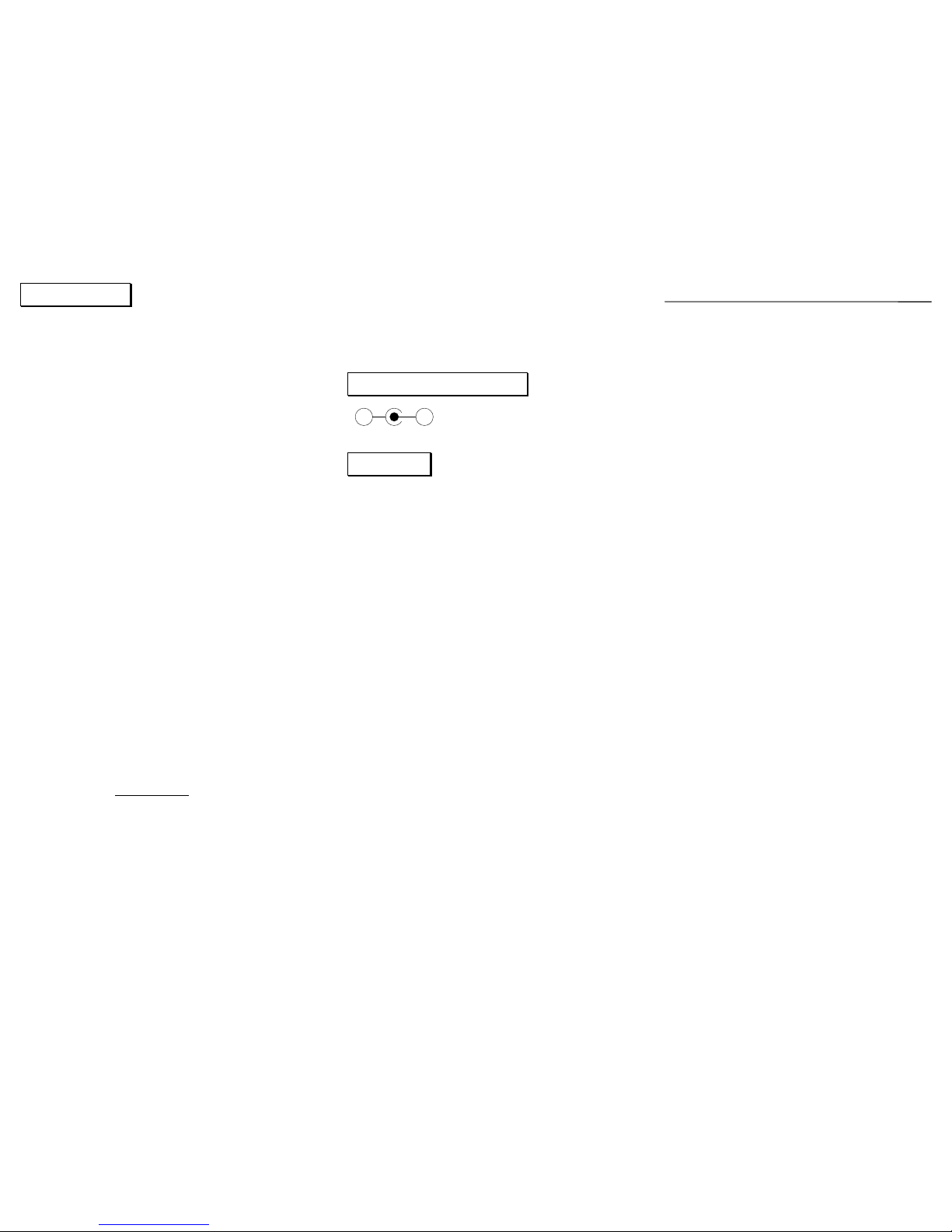
+ -
Overview
The GRX4 has been designed to operate in one of two
modes. Program Change mode allows the GRX4 to be
used with MIDI footcontrollers that can only transmit MIDI
Program Change messages or have run out of Control
Change messages... Control Change mode is geared
towards MIDI footcontrollers that have instant access
switches and are capable of transmitting MIDI Control
Change messages. The GRX4 has four (4) Control
Change modes, CC1 - CC4.
When operating in Program Change mode, the GRX4 will
respond to MIDI Program Change messages on the user
selected MIDI Channel. The loops will either be latched or
momentary, depending on the “Edit Loop Configuration”.
All MIDI Control Change messages will be ignored.
When operating in one of the four Control Change modes,
the GRX4 will respond to MIDI Control Change messages
on the default MIDI Channel. The MIDI Program Change
Channel and Loop Configuration will be cleared and
disabled, all Program Change messages will be ignored.
Basic Operation
Connect a MIDI footcontroller and the effects and/or amp
to be routed/switched/controlled to the GRX4 as described
in the “Connections” section.
Apply power to the GRX4 first, then to the effects and
amp. Ensure the effects are active and use the MIDI
footcontroller to access the four loops... When done,
remove power from the amp and effects first, then from the
GRX4.
To edit a preset in Program Change mode, select the
preset to edit using the MIDI footcontroller. Press and/or
hold the EDIT switch until the desired combination of loops
(on/off) is selected. The preset is automatically stored in
the GRX4’s EEPROM memory. As a safety feature, only
the LEDs will change when holding the EDIT switch down.
The loops will switch after the EDIT switch has been
released.
!!ATTENTION!!
ON POWER-UP, ALL LOOPS ARE OFF (BYPASSED).
ON POWER-UP, IN PROGRAM CHANGE MODE, THE
EDIT SWITCH HAS NO EFFECT UNTIL A PRESET IS
SELECTED USING THE MIDI FOOTCONTROLLER.
THE EDIT SWITCH HAS NO EFFECT WHEN IN ONE OF
THE FOUR CONTROL CHANGE MODES.
Edit Program Change Channel
This allows the selection of which MIDI Channel the GRX4
will receive MIDI Program Change messages on.
Power-off the GRX4. Press and hold the EDIT switch and
apply power to the GRX4. Wait for all the LEDs to flash
one time and release the EDIT switch. You are now in
“Edit Program Change Channel”. Pressing the EDIT switch
will allow you to scroll through the sixteen different MIDI
Channels. To save your selection in the GRX4’s EEPROM
memory, simply power-off the GRX4.
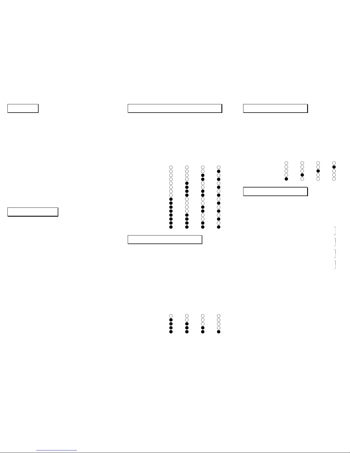
Channel #10
Channel #11
Channel #12
Channel #13
Channel #14
Channel #15
Channel #16
Channel #9
CHANNEL L4-LED L3-LED L2-LED L1-LED
Channel #1
Channel #2
Channel #3
Channel #4
Channel #5
Channel #6
Channel #7
Channel #8
Edit Loop Configuration
This allows the selection of which loops are latched and
which are momentary, when in Program Change mode.
Please note that the ability to make loops 1 - 3 momentary
has been included for customization purposes only.
Typically, only Loop 4 might need to be configured for
momentary switching if used as a control function...
Power-off the GRX4. Press and hold the EDIT switch
and apply power to the GRX4. Wait for all the LEDs to
flash two times and release the EDIT switch. You are now
in “Edit Loop Configuration”. Pressing the EDIT switch will
allow you to scroll through the different loop configurations.
To save your selection in the GRX4’s EEPROM memory,
simply power-off the GRX4.
CONFIGURATION L4-LED L3-LED L2-LED L1-LED
L4/3/2/1 Latched
L4 Mom & L3/2/1 Lat
L4/3 Mom & L2/1 Lat
L4/3/2 Mom & L1 Lat
L4/3/2/1 Momentary
Edit Operating Mode
This allows the selection of the GRX4’s operating mode.
Power-off the GRX4. Press and hold the EDIT switch and
apply power to the GRX4. Wait for all the LEDs to flash
three times and release the EDIT switch. You are now in
“Edit Operating Mode”. Pressing the EDIT switch will allow
you to scroll through the different modes of operation. To
save your selection in the GRX4’s EEPROM memory,
simply power-off the GRX4.
MODE L4-LED L3-LED L2-LED L1-LED
Program Change
Control Change CC1
Control Change CC2
Control Change CC3
Control Change CC4
MIDI Implementation
Model & F/W: GRX4
Version 2
Revision 5
MIDI Channel: Default: 161
(Received) Changed: 1 - 16
2
Control Change: 80 - 833 L1 - L4 Latching
(Received) 104 - 107
3
L1 - L4 Momentary
84 - 87 L1 - L4 Latching
108 - 111 L1 - L4 Momentary
88 - 91 L1 - L4 Latching
112 - 115 L1 - L4 Momentary
92 - 95 L1 - L4 Latching
116 - 119 L1 - L4 Momentary
Control Value 0 = Off
Control Value 127 = On
Program Change: 1 - 128 Selects memory
(Received) locations 1 to 128
Notes: 1. Fixed for Control Changes.
2. User selectable for Program
Changes, stored in EEPROM.
3. The GRX4 is shipped from the
factory in Control Change CC1
operating mode.
4. For DMC Ground Control users:
CC1 = GCX#1 Loops 1 - 4
CC2 = GCX#1 Loops 5 - 8
CC3 = GCX#2 Loops 1 - 4
CC4 = GCX#2 Loops 5 - 8
CC1
CC2
CC3
CC4
 Loading...